

Page 1

Table of Contents
Features.........................................................................................................................................................1
Technical Specifications (Typical Unit):..............................................................................................2
Receiver:.........................................................................................................................................2
Transmitter:..................................................................................................................................2
Simplified Technical Description:.........................................................................................................3
MFJ-8621 Technical Description:......................................................................................................3
General:...........................................................................................................................................3
Receiver:.........................................................................................................................................3
Transmitter:..................................................................................................................................3
T/R Switching:.............................................................................................................................3
TNC Data Carrier Detect Compatibility............................................................................................4
Connecting To Your MFJ-8621:..........................................................................................................4
Power Supply:...............................................................................................................................4
Antenna:..........................................................................................................................................5
TNC Connection:..........................................................................................................................5
RFI:.....................................................................................................................................................5
Selecting Baud Rate:................................................................................................................................6
Receiver Filter:..............................................................................................................................6
Transmitting:.................................................................................................................................6
Transmitter Deviation:.............................................................................................................................6
Setting Deviation:........................................................................................................................6
Two-Way Deviation Monitoring:............................................................................................7
Confirming Deviation:................................................................................................................7
Ordering Crystals:......................................................................................................................................8
Receiver Crystal:..........................................................................................................................8
Transmitter Crystal:...................................................................................................................8
Installing Crystals:......................................................................................................................................9
Crystal Oscillator Calibration:................................................................................................................10
Transmit Oscillator:....................................................................................................................10
Receiver Oscillator:.....................................................................................................................10
More About 9600-Baud FSK Packet Signals:...............................................................................11
Sending And Receiving 9600-Baud Data:.......................................................................................11
In Case Of Difficulty:...................................................................................................................................12
1. Unable To Copy Off-Air Signals:........................................................................................12
2. Unable To Connect:...............................................................................................................12
3. Transmitter Erratic Or Inoperative:...............................................................................12
Important Operator Notes:....................................................................................................................12
Appendix.........................................................................................................................................................13
Technical Assistance.................................................................................................................13
Replacing The Fuse Link...........................................................................................................13
Page 2

MFJ-8621 Data Radio
MFJ-8621 2-Meter Packet Only
Congratulations on your choice of the MFJ-8621 Packet Only Data Radio. Please read
this manual thoroughly before attempting to operate your unit. Let's begin with a look
at some useful MFJ-8621 Features:
FEATURES
Packet-Only Performance: The MFJ-8621 is designed from the ground up for packet.
This means you'll get uncompromising performance at all data rates--on AFSK or FSK-for a fraction of what you'd pay for a converted voice radio.
Cool Running: The MFJ-8621 draws only 25 mA on receive, and less than 1 A on
transmit. Run it 24 hours a day 365 days a year, or pack it with your lap-top and take
it on the road.
Sensitive: Motorola-IC based receiver circuitry recovers data from weak signals for
better throughput and fewer collisions.
Made-For-Data Filters: Optimi ze your receiver for wide 9600-baud signals or narrow
1200-baud signals. No other radio does this!
Rugged 5-Watt Transmitter: All the power you need to get the job done without
creating needless interference at distant nodes.
Clean Unsquelched Data Output: The MFJ-8621 uses a wide-response DC-coupled
line driver rather than a speaker amp for flawless signal recovery.
Note: Your TNC must have full DCD (Data Carrier Detect) in order to work with radios
that have full unsquelched AFSK output.
Lightning-Fast TXD: Set TXD low! PIN-diode switching, continuous-running receiver,
and crystal control deliver ultra-fast switching.
Twin Modulators: Varactor-modulation for true-FM at 9600-baud and reactance
modulation for mic-level signals at 1200 baud provide ultra-clean FSK and AFSK.
Simple Setup: The MFJ-8621 is compatible with virtually all up-to-date TNC-2 modems.
Easy To Rechannel: Run your MFJ-8621 with supplied crystals on 145.01 MHz, or
order custom cry stals for t he channel of your choi ce. Simple step- by-step instr uctions
illustrate how to exchange crystals and set on frequency without expensive test
equipment.
The Right Tool For The Job: Your MFJ-8621 was designed from scratch for fast,
clean packet communication and nothing else! Whether you are monitoring the local
DX cluster or breaking new ground at 9600, you can look forward to years of hands-off
service.
Data Radio
1
Page 3
MFJ-8621 Data Radio
TECHNICAL SPECIFICATIONS (Typical Unit):
Receiver:
Frequency Coverage................. 144-148 MHz
Sensitivity....................................... 0.6 µV for 12 dB Quieting
Image Rejection.......................... -45 dB or better
1st IF................................................ 10.7 MHz
2nd IF.............................................. 455 KHz
1st LO............................................. Crystal , 3rd overtone
2nd LO............................................ 10.245 MHz
Selectivity....................................... -6 dB at 20 KHz (data-passband filter)
AFSK Output................................. Unsquelched, 0dBm @ 3.0-KHz deviation
Current Drain.............................. 25 mA
Transmitter:
Frequency Control.................... Crystal, 18-MHz x 8
FSK/AFSK Input level.............. 150 mV p-p @ 1200 baud, .8 V p-p @ 9600
Deviation........................................ 0-5 KHz, adjustable at TNC
RF Power Output....................... 4.0 - 5.0 Watts into 50 Ohms
VSWR Tolerance....................... 3:1 Max.
Current Drain.............................. 1.0 Amp @ 13.8 Volts
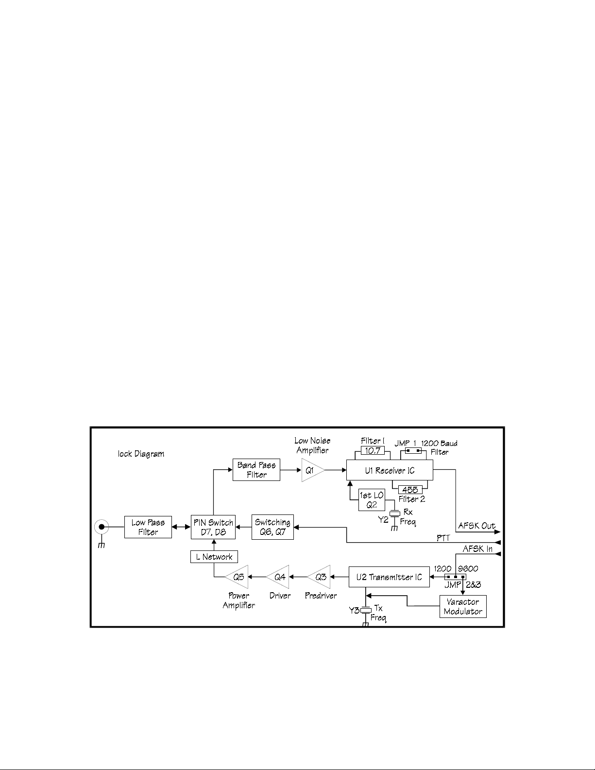
Figure 1 Block Diagram of MFJ-8621 Data Transceiver
2
Page 4

MFJ-8621 Data Radio
SIMPLIFIED TECHNICAL DESCRIPTION:
Your MFJ-8621 was especially designed for packet-only operation. MFJ has
eliminated costly circuitry that you don't need: such as squelch, repeater offsets, PL
tones, DTMF pad, PLL synthesis, memory, and the speaker-amplifier. At the same
time, we engineered in essential packet circuits like true-FM direct modulation,
unsquelched AFSK, PIN-diode switching, data-passband IF filtering, and a tailored 0-Vu
DC-coupled line driver to ensure top-no tch performance. There are no user-adjustable
controls to set incorrectly, and the MFJ-8621 works with most popular TNCs.
MFJ-8621 TECHNICAL DESCRIPTION:
General:
The MFJ-8621 is a dedicated-channel 2-Meter FM-AFSK transceiver designed for use
DCD equipped
with
Receiver:
Referring to Figure 1, incoming signals are preselected by the lowpass and bandpass
filters. Low-noise preamp Q1 enhances weak sign al performance. U1 is a monolithic
dual-conversion narrowband-FM receiver IC that provides all mixer, IF amplification,
limiting, and audio functions. The 1st-LO, Q2, is an external 3rd-overtone oscillatortripler and the 2nd LO is built into U1. U1 and Q2 remain powered during transmit to
ensure seamless RX recovery and self-monitoring capability. IF passband filtering is
provided by ceramic filters FL1 (10.7 MH z) and FL2 (455 KHz) . FL2 is a 20-KHz databandwidth filter which supports 9600 baud operation. Discriminator output is looped
to U1's auxiliary op-amp which is configured as a DC-coupled AFSK line driver. Gain is
set to provide 0-dBm AFSK output into a 600-Ohm load for approximately 3.0 KHz
deviation. A jumper configures t he line driver feedback loop for HF noise reduction at
1200 baud AFSK reception. Test points at the 1st-LO, RSSI, and DISC outputs
facilitate alignment.
Transmitter:
FM signals are generated by monolithic FM-transmitter IC U2. Frequency control is
provided by 18-MHz crystal Y3 (oscillator/modulator output is multiplied by three
successive doubler stages to 145 MHz). 1200-baud AFSK is fed directly to the IC's
reactance modulator. 9600-baud FSK is fed through a varactor modulator for trueFM modulation. Pre-driver Q3 and Driver Q4 operate in class AB and use tuned bifilar
4:1 interstage transformers to facilitate matching and bandpass filtering. The PA
stage (Q5) is a conventional class-C amplifier with a tuned-L network and pi-section lowpass filter to provide Z-matching and harmonic suppression.
T/R Switching:
RF switching is executed by PIN diodes D8 (receive path) and D7 ( transmit path). DC
switching is executed by Q6, Q7. Supply voltage to U1 is regulated at 5 volts, and
voltage to U2 is regulated at 8 Volts. The 1st-LO voltage is regulated at 6.8 Volts.
Receiver chip U1 remains powered during transmit for seamless T/R switching
characteristic. The MFJ-8621 is designed to operate at 13.8-Volts @ 1-Amp.
TNC-2 style modems at data-rates through 9600 baud.
TNC DATA CARRIER DETECT COMPATIBILITY
3
Page 5

MFJ-8621 Data Radio
As a "packet-only" radio, the MFJ-8621 is specially designed to transmit and receive all
data rates through 9600 baud. However, to accomplish this, the MFJ-8621 must
deliver
squelched AFSK because conventional squelch circuits are far too slow to be useful
above 1200 baud. In order to process unsqu elched data from the MFJ-8621 (or any
high speed data radio), your TNC must have a data carrier detect (DCD) circuit built in.
All MFJ model TNCs -- starting with t he MFJ-1270B-- and virtually any other TNC that
operates over 1200 baud should have one as well (PK-96, DPK-9600 for example).
Unfortunately, many TNCs, like the PK-232 and even some low cost mini-TNCs, lack
DCD because they are made exclusively for use with conventio nal FM voice radios to
run at 1200 baud. If your TNC does not have DCD, it cannot distinguish between
limiter noise (the strong rushing noise FM radios produce with no signal present) and
data signals. Since the TNC sees the limiter noise as incoming signal, it will not allow
the TNC to transmit due to the TNC's data collision protection function. Consequently,
the radio will appear incapable of transmitting! Again, your TNC
work with the MFJ-8621.
If your TNC
Read your TNC documentation carefully to confirm what type of carrier detection--if
any--exists in your unit. If you do have DCD, activate it.
unsquelched
does
AFSK or FSK data to the TNC. The MFJ-8621 does not provide
must
have DCD to
have a DCD, make sure the function is enabled in your particular unit.
Important Note:
Some TNC's have software DCD circuits that may also require internal adjustments
(check your TNC manual and follow activation instructions carefully). Other TNCs may
not have a DCD at all or have a DCD indicator that is really nothing more than a mislabeled "signal-present" indicator. Separate "universal" add-on DCD circuits are
available for TNCs that lack a DCD. PacComm offers add-on DCD circuits for many
applications and has information about choosing the right DCD to fit your needs.
Refer to the appendix for notes on specific TNCs.
CONNECTING TO YOUR MFJ-8621:
Power Supply:
The MFJ-8621 will operate from any well-filtered DC power source delivering 13.8
Volts at 1 Amp. The MFJ-4110 wall-adapter supply is a light-weight voltage-regulated
unit especially suited for powering the MFJ-8621. "CB" type supplies or battery packs
capable of 1-A output will also work (anticipate lower RF output when using a 12-volt
source). The MJF-8621 accepts a standard 5.5mm x 2.1mm coaxial-type power plug
(Radio Shack 274-1569). Connect t he (+) or red lead to the cent er pin, and connect
the (-) or black lead to the outer sleeve. Use a 2 amp fast-blow fuse with any power
supply other than the MFJ-4110. Your MFJ-8621 features "crowbar" protection to
prevent damage from incorrect power supply polarity. If power leads are accidentally
reversed, the crowbar-diode conducts and immediately opens the radio's line fuse,
cutting off power (for line-fuse replacement instructions, see the Appendix).
4
Page 6

MFJ-8621 Data Radio
Antenna:
For best packet performance, use a high-quality antenna adjusted for minimum VSWR
at your operating frequency. Omni-directional types--like the MFJ-1740 1/4-wave
ground plane, MFJ-1750 5/8-wave ground plane, or MFJ-1764 dual 5/8-wave Super
gain-should provide excellent area coverage. If you need added punch to gain reliable
access into a busy regional node, install a directional antenna--like the MFJ-1763 3element 2-Meter beam. When installing the antenna, be sure to feed it with highquality low-loss coax and keep the cable run as short as possible. In many cases, a
lower antenna fed with good cable will outperform a higher antenna fed with lossy
cable. To cut line losses to a minimum, avoid adding unnecessary in-line connectors,
power meters, and coax switches.
TNC Connection:
The MFJ-8621 plugs directly into any M FJ TNC starting with the MFJ-1270B. Any
other DCD equipped TNC, such as the PK-96 and many others, will also work with this
data radio. Use a 5-pin DIN-to-5-pin DIN cable, MFJ-5100, for connection to MFJ
TNCs or the PK-96.
Caution: Not All TNCs have DCD (Data Carrier Detect) circuitry, and your MFJ-8621 --
which has an unsquelched output---will not work with those TNCs.
Pin Function
1 AFSK IN (150 mV pp / 800 mV pp)
2 GND
3 PTT (ground or logic-low for TX activation)
4 AFSK OUT (2.2 V pp into 600 Ohms)
5 N.C.
RFI:
After completing initial adjustments, always reinstall the covers on your MFJ-8621 and
TNC. Without shielding, the receiver may be swamped with RF interference generated
by microprocessors in the computer and TNC. For added RFI protection, many
veteran packet operators recommend installing ferrite RFI chokes on interconnect and
power cables--and keeping the radio as f ar as possible from the TNC and computer.
The MFJ-701 RFI kit provides 4 snap-on chokes for this purpose, along with
instructions. Snap-o n RFI chokes are also available at Radio Shack (273-104 and 273-
105).
5
Page 7

MFJ-8621 Data Radio
SELECTING BAUD RATE:
Receiver Filter:
The MFJ-8621 receiver features a special noise-reduction filter to enhance 1200baud operation. When running at 1200-baud, this filter improves weak-signal
performance. To activate the 1200-baud noi se-reduction filter, install a shor ting plug
at JMP-1 (this plug must always be removed when operating at 9600-baud).
See Figure 3 on page 9 for placement of the jumpers on the pc board.
Transmitting:
The MFJ-8621 has two FM modulators selected by jumpers, JMP2 and JMP3. One is
a sensitive
TNC's output mic-level si gnals at 1200 baud, the reactance modulator should be used
at 1200 baud. The other is a "true-FM"
FSK signals. At 9600 baud, most TNC's have a line-level output and should be used
with the varactor m odulator. If your TNC has a li ne-level outpu t setting f or 1200 baud
TX-AFSK (usually set via a jumper inside the TNC), you may use the varactor modulator
at both data rates.
For 1200-baud AFSK operation, install JMP1 and set JMP-2 and JMP-3 in the
reactance modulator positions (left-hand and center pins of each header).
For 9600-baud FSK operation, remove JMP1 and set JMP-2 and JMP-3 in the
varactor modulator positions (center and right-hand pins of the headers).
reactance modulator
designed for
varactor modulator
mic-level
AFSK signals. Since most
designed for
line-level
See Figure 3 on page 9 for placement of the jumpers on the pc board.
IMPORTANT NOTE: JMP1, JMP2 and JMP3 are set for 1200 baud at the factory.
Always recalibrate the MFJ-8621 transmitter oscillator for frequency (L6)
after switching modulators (see calibration, page 10).
TRANSMITTER DEVIATION:
Setting Deviation:
The MFJ-8621 has no internal deviation control. Deviation is adjusted via the AFSK
output level control on your TNC (consult your TNC manual for specifics). If you don't
have access to a FM deviation meter, you can set deviation by measuring the peak-topeak AFSK signal output from your TNC:
With jumpers in the
p sine wave should produce approximately 3-KHz deviation. With jumpers in the
varactor modulator
produce approximately 3-KHz deviation.
Virtually any calibrated oscilloscope will allow you to make this measurement. Connect
your scope probe t o PIN-1 on the 5-pin DIN j ack at either the TNC or radio end (look
for the TX-AFSK line if your TNC uses a different type of jack). Use the CALIBRATE
function on your TNC to generate a test-tone.
reactance modulator
(9600-baud) jumper positions, a 800-mV p-p sine wave should
(1200-baud) jumper positions, a 150-mV p-
6
Page 8

MFJ-8621 Data Radio
Figure 2 Monitoring Incoming and Outgoing Signals with a Scope
Two-Way Deviation Monitoring:
In addition to monitoring TNC output at pin 5, you may also monitor both incoming and
outgoing Packet signals passin g through your statio n by connectin g an oscillosco pe to
the RX-AFSK line at pin-4. RX-AFSK also appears at the "monitor" or "speaker" jack on
most TNCs. Use 1-V/div V-sens and 1-ms/div H-time base. To set TX deviation while
monitoring RX-AFSK, first note the waveform height of average off-air signals (2.2 V p-p
is typical for 3-KHz deviation). Next, key the MFJ-8621 transmitter via the CALIBRATE
function on your TNC--and adjust TNC output (TX-AFSK) for a waveform of about the
same height.
Confirming Deviation:
If a node in your area uses the X-1J2 version of theNET, you can take advantage of that
station's built-in deviation meter to confirm the accuracy of your setting. Anytime you
experience consistent difficulty connecting with local stations, you should suspect
improper deviation level as a possible cause.
7
Page 9

MFJ-8621 Data Radio
ORDERING CRYSTALS:
You may order crystals for other channels factory-direct. Crystal specifications are:
Receiver Crystal:
XTAL Freq. =
TYPE................................................. 3rd overtone (44-MHz range)
TOLERANCE................................... .003% Commercial Standard
TEMPERATURE............................ 26-Degrees C (room temperature)
LOAD................................................ Series
CASE................................................. HC-25U or FM-2
Transmitter Crystal:
XTAL Freq. =
TYPE.................................................. Fundamental Mode (18-MHz range)
TOLERANCE.................................... .003% Commercial Standard
TEMPERATURE............................. 26-Degrees C (room temperature)
LOAD.................................................. 32 pF, Parallel
CASE.................................................. HC-25U or FM-2
Crystals for the MFJ-8621 may be ordered directly from:
JAN Crystals
P.O. Box 06017, 2341 Crystal Drive
Fort Myers, FL 33906-6017
Telephone (800) 526-9825, FAX (813) 936-3750
When ordering from JAN, simply tell the sales person that you wish to order a pair of
crystals for the MFJ-8621 Data Radio and give the
has complete MFJ-8621 crystal specifications on file in their ordering system and no
additional information is required. Alternatively, you may purchase crystals from:
International Crystal Manufacturing Co., Inc. (ICM)
P.O. Box 26330, 701 W. Sheridan
Oklahoma City, OK 73123-0330
Telephone: (405) 236-3741, FAX (405) 235-1904
For receiver crystals, order 471270-CRYSTAL FREQ (not the operating freq.)
For transmitter crystals, order 434275-CRYSTAL FREQ (not the operating freq.)
JAN and ICM both welcome telephone orders and accept MasterCard or Visa.
Operating Freq. - 10.7 MHz
3
Operating Freq.
8
operating frequency
in MHz. JAN
8
Page 10

MFJ-8621 Data Radio
INSTALLING CRYSTALS:
To install new crystals in your MFJ-8621, refer to the diagram below:
[ ] Remove the MFJ-8621 cabinet lid (one screw on each side of the cabinet).
[ ] Locate and pull the existing transmit crystal (Y3) from its socket.
[ ] Carefully plug the new transmit crystal in its place.
[ ] Locate and pull the existing receive crystal (Y2) from its socket.
[ ] Carefully plug the new receive crystal in its place.
Figure 3 Crystal Locations and Calibration Adjustment Points.
For future reference, label your pull-out crystals for operating frequency and store
them in a safe place.
Anytime you install new crystals, you must readjust L4 and L6 for exact frequency
calibration on the new channel (see page 10). Do not attempt to operate your radio
until this calibration procedure has been completed.
9
Page 11

MFJ-8621 Data Radio
CRYSTAL OSCILLATOR CALIBRATION:
Transmit Oscillator:
To measure the exact operating frequency of the MFJ-8621 transmitter, monitor the
radio's RF output signal with a digital frequency counter. To obtain a usable signal
sample, place the counter's pickup antenna near the MFJ-8621 PA section--or install a
sampling tap in the coax line leading to your dummy load. Use the CALIBRATE function
on your TNC or short pin-3 of the data jack (PTT Line) to ground to key your
transmitter's PTT line. Refer to Figure 3 on page 9 for specific locations on the pc
board.
[ ] Key the PTT line and check for a stable counter reading.
[ ] Using an insulated tuning wand, adjust L6 to the exact operating frequency.
[ ] Key and unkey the transmitter a couple of times to confirm setting.
Alternatively, if you don't have access to a good VHF counter, you may use a
synthesized HF receiver for approximate calibration. To pick up the transmitter
crystals fundamental signal, place a short antenna pickup wire near the MFJ-8621
and tune your HF receiver to the exact frequency stamped on the transmit crystal
case (in the 18-MHz range). Next, key the transmitter PTT line and adjust L6 for zero
beat. You must be precise; any frequency error appearing at 18 MHz will be multiplied
8 times at 145 MHz!
Receiver Oscillator:
Your MFJ-8621 has a unique built-in feature that allows you adjust the receiver
oscillator by using the calibrated MFJ-8621 transmitter signal as a reference. You'll
need a accurate DC voltmeter (or DVM) and an insulated tuning wand for this
adjustment. Refer to Figure-3 for locations on the pc board:
[ ] Locate DISC-TP (discriminator test point) in front of the radio's data jack.
[ ] Set up voltmeter to measure DC readings in the 3-volt range.
[ ] Connect the voltmeter to DISC-TP.
[ ] Key the transmitter on.
[ ] Adjust L4 for a DISC-TP reading of 2.5 volts.
The MFJ-8621 is now calibrated to transmit and receive on the same frequency.
To calibrate your MFJ-8621 receiver for a frequency different than the transmitter (i.e.
for split-channel operation), you can substitute a 2-Meter HT for your signal source.
First, connect a dummy load to the HT antenna jack (a 47-Ohm 1/4-W resistor is
okay). Set your HT for low-power simplex operation and dial in the desired calibration
frequency. Now, follow the procedure outlined above, substituting the HT as your
signal source.
10
Page 12
MFJ-8621 Data Radio
MORE ABOUT 9600-BAUD FSK PACKET SIGNALS:
The familiar "braaap" generated by 1200-baud packet signals is a combination of
1200 and 2200-Hz sine- wave tones beatin g together. Altho ugh the info rmation bei ng
conveyed by these tones is digital, the transmission system itself is analog and falls
within the range of norm al speech. Unlike 1200-baud packet, 9600-baud signals are
transmitted by binary FSK. To understand how this works, suppose you set your radio
at 145.000 MHz with the modem adjusted for 3-KHz deviation. Anytime the TNC
sends a 1, the transmitter should flip 1.5 KHz high in frequency to generate a carrier
at 145.0015 MHz. When the TN C sends 0, the transmitter sho uld flop 1.5 KHz low
to generate a carrier at 144. 9985 MHz. This is called FSK-FM ( frequency-shift key ed
FM), and there are no analog tones involved--only a rapid switching back and forth
between binary states. In fact, 9600-bau d signals sound more like white noise rather
than tones when monitored on a conventional FM receiver. Data signals of this type
require significantly more bandwidth than normal speech. Extended low-frequency
response is needed to sustain prolonged strings of 1s or 0s, and extended highfrequency response is needed to provide a fast rise time when the signal changes
state. This is why 9600-baud r eceivers typi cally use wi der IF filt ers and specia l RX-FSK
output circuits--and why transmitters often use "direct-FM" modulators which are
especially adapted for FSK.
SENDING AND RECEIVING 9600-BAUD DATA:
Although 9600 baud packet is much faster than 1200 baud, it is also much less
forgiving of marginal signal paths. For one thing, you'll probably need about 5-6 dB in
additional signal strength to overcome wideband noise generated by the receiver's
unusually-broad IF and audio passbands. Also, 9600-baud signals are extremely
vulnerable to phase shift, which means multi-path reflections between stations must be
held to a minimum. Finally, your transmitter and receiver must be accurately adjusted
to frequency and the transmit deviation set for the correct shift.
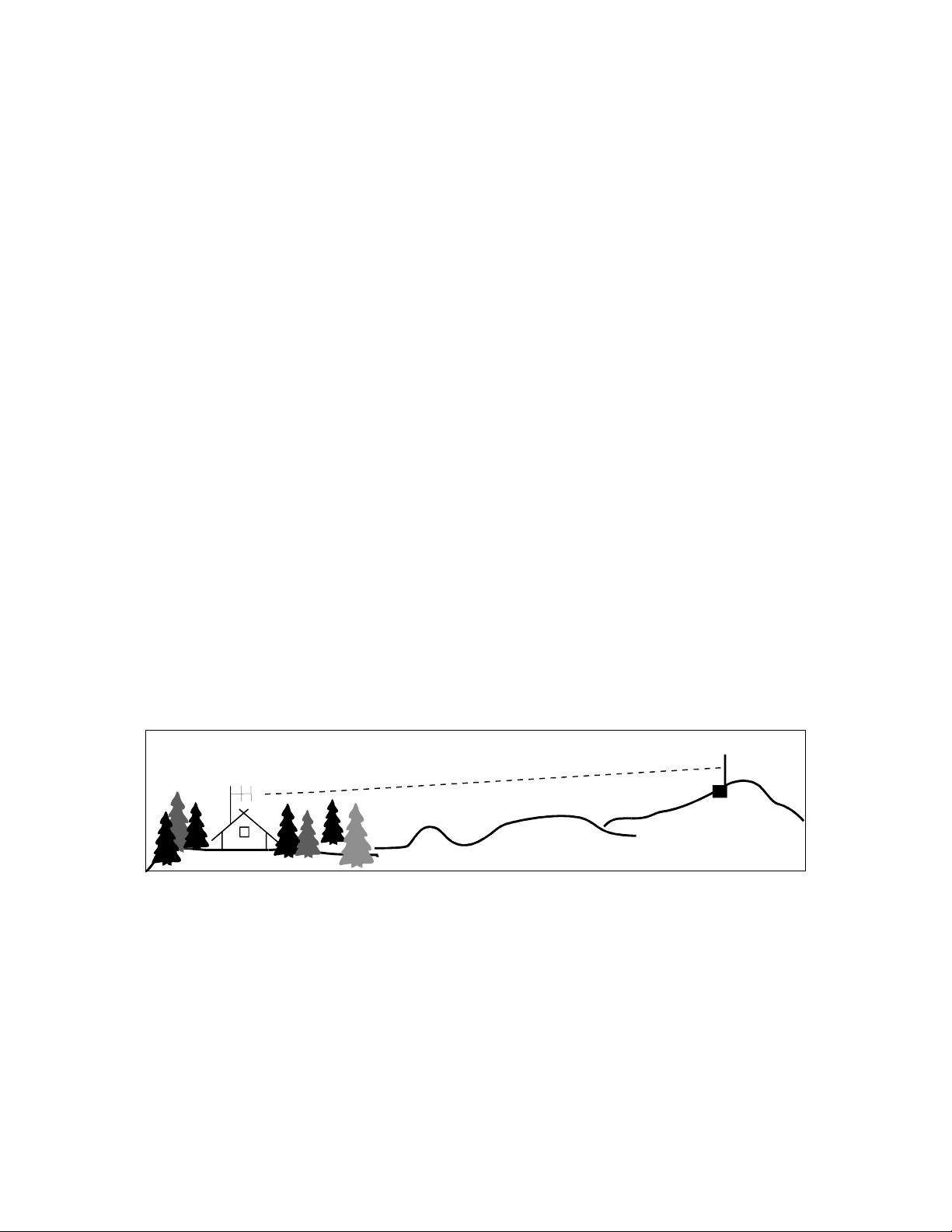
It's best to think "pipeline" when setting up point-to-point 9600-baud links. A carefullyaimed yagi generally provides better quieting and less multi-path than omni-directional
antennas. If you are selecting a remote site for your station, please remember the
MFJ-8621 is a $120 amateur radio product and not a $5000 commercial repeater!
Avoid high-IMD locations if you can, or be prepared to provide additional filtering to
reduce the effects of intermod and desensing from nearby transmitters. Also, avoid
unheated buildings; the MFJ-8621 does not come equipped with a crystal oven to
maintain its operating frequency over a wide temperature ran ge. Finally, make certain
your transmitter is not interfering with commercial services sharing the site. Setting
up a node for 9600 takes a little more care, but once you are "up and running", you
can sit back and watch massive files pump through in a matter of seconds!
11
Page 13

MFJ-8621 Data Radio
IN CASE OF DIFFICULTY:
Many equipment problems can be traced to simple setup errors or minor
malfunctions that are easily corrected. Before contacting the MFJ factory for help,
please take a few minutes to read through the list of symptoms below and check out all
appropriate suggestions. If the problem persists, refer to the technical assistance
section in the Appendix.
1. Unable To Copy Off-Air Signals:
[ ] Improper TNC setup (consult TNC manual and double-check setup).
[ ] Defective antenna or interconnect cables (check for shorts, opens, etc.).
[ ] TNC or computer RFI (install cabinet covers, check cable shields).
[ ] Wrong crystal installed at Y2 (RX crystal should be in the 44-MHz range).
[ ] 1200-baud filter on, blocking 9600-baud reception (remove JMP-1).
2. Unable To Connect:
[ ] Transmitter or receiver off-frequency (see crystal-oscillator calibration).
[ ] Incorrect deviation (see FM-deviation adjustment).
[ ] Trying to copy 9600-baud data with AFSK filter on. (Remove JMP-1).
[ ] Using wrong modulator (consult manual, check JMP-2, JMP-3).
[ ] Insufficient signal strength (check antenna orientation).
[ ] Node overloaded with traffic (wait for things to quiet down).
3. Transmitter Erratic Or Inoperative:
[ ] Insufficient power source (check voltage of power supply under load).
[ ] Wrong crystal installed at Y3 (crystal should be in the 18-MHz range).
[ ] High-VSWR antenna (check antenna with bridge -- should be 2:1 or less).
[ ] Transmitter locked out because TNC is not equipped with DCD circuit.
IMPORTANT OPERATOR NOTES:
Your MFJ-8621 is specially designed to work with TNCs that are DCD equipped. If
your TNC does not have data carrier detect circuitry, it will read the MFJ-8621's
unsquelched audio as an incoming signal and will not allow the data radio to transmit.
Your MFJ-8621 is not VSWR protected and will not tolerate prolonged operation into
high-VSWR antennas. Most commercial antenna installations provide a VSWR or
1.5:1 or less, and this is a good rule of thumb to follow for VHF amateur installations.
Also, do not retune RF circuits in your MFJ-8621; this should only be done at the
factory by a trained technician with access to correct procedures and instrumentation.
MFJ cannot be held responsible for the on-air performance of radios subjected to
unapproved tampering.
Finally, the MFJ-8621 is not FCC type accepted for commercial radio service and is
intended solely for amateur use. Do not attempt to adapt this unit for commercial
applications, and always test for interference to other radio services when using the
MFJ-8621 in amateur service at a shared commercial site.
12
Page 14
MFJ-8621 Data Radio
APPENDIX
Technical Assistance
If you have any problem with this unit first check the appropriate section of this manual.
If the manual does not reference your problem or your problem is not solved by
reading the manual, you may call
Factory
at 601-323-5869. You will be best helped if you have your unit, manual and
MFJ Technical Service
at 601-323-0549 or the
MFJ
all information on your station handy so you can answer any questions the technicians
may ask.
You can also send questions by mail to MFJ Enterprises, INC., 300 Industrial Park
Road, Starkville, MS 39759; by FAX to 601-323-6551; through Compuserve at
76206,1763; or by email to [email protected]. Send a complete
description of your problem, an explanation of exactly how you are using your unit, and
a complete description of your station.
Replacing the Fuse Link
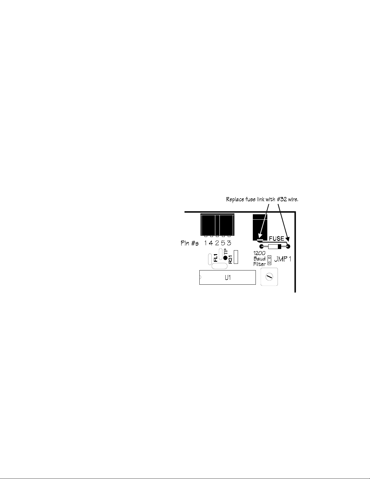
The MFJ-8621 has a thin foil trace on the pc board that acts as a line fuse. This trace
connects power to the rest of the circuitry and may "burn out" under certain
conditions (such as when the MFJ-8621 is subjected to a reversed polarit y power). If
your Data Radio do es not operate and you suspect that the line fuse is broken follow
these steps:
1. Remove the cover and inspect the
fuse line. It may be necessary to
test the fuse for continuity.
2. If the line is broken replace it with a
length of #32 wire of approximately
the same length. You may optionally
replace the line with a heavier gauge
of wire and protect the unit with a 2
amp fast-blow fuse.
3. Replace the cover and screws.
DCD Setup
To use the KPC-9612 at 9600 baud with the MFJ-8621:
1. Enter the command CD SOFTWARE at the cmd: prompt.
2. Set the 9600 receive level jumper (J9) to "ON" (both pins shorted together).
3. Set the 9600 equalization header for "variable" (pin 2 shorted to center).
4. Set the 9600 equalization pot (R33) from approx. 11 to 12 o' clock.
5. Set 9600 baud drive jumper (J7) to low range (jumper one pin only).
6. Set the 9600 baud drive control (R32) to midrange.
To use the KPC-3 at 1200 baud with the MFJ-8621:
1. Enter the command CD SOFTWARE at the cmd: prompt.
2. Set the AFSK level jumper (J3) to "high range" (both pins shorted together).
3. Set the 1200 tran smit drive level control (R13) to 3.5 KHz. transmit deviation as
described in your KPC-3 reference manual.
13
Page 15

MFJ-8621 Data Radio
FULL 12 MONTH WARRANTY
MFJ Enterprises, Inc. warrants to the original owner of this product, if manufactured by MFJ
Enterprises, Inc. and purchased from an authorized dealer or directly from MFJ Enterprises, Inc.
to be free from defects in material and workmanship for a period of 12 months from date of
purchase provided the following terms of this warranty are satisfied.
1. The purchaser must retain the dated proof-of-purchase (bill of sale, canceled check, credit
card or money order receipt, etc.) describing the product to establish the validity of the
warranty claim and submit the original of machine reproduction or such proof of purchase
to MFJ Enterprises, Inc. at the time of warranty service. MFJ Enterprises, Inc. shall have
the discretion to deny warranty without dated proof-of-purchase. Any evidence of
alteration, erasure, or forgery shall be cause to void any and all warranty terms
2. MFJ Enterprises, Inc. agrees to repair or replace at MFJ's option without charge to the
3. MFJ Enterprises, Inc. will supply replacement parts free of charge for any MFJ product
4. This warranty is NOT void for owners who attempt to repair defective units. Technical
5. This warranty does not apply to kits sold by or manufactured by MFJ Enterprises, Inc.
6. Wired and tested PC board products are covered by this warranty provided only the
7. Under no circumstances is MFJ Enterprises, Inc. liable for consequential damages to
8. Out-of-Warranty Service: MFJ Enterprises, Inc. will repair any out-of-warranty product
9. This warranty is given in lieu of any other warranty expressed or implied.
10. MFJ Enterprises, Inc. reserves the right to make changes or improvements in design or
11. All MFJ products to be serviced in-warranty or out-of-warranty should be addressed to
12. This warranty gives you specific rights, and you may also have other rights which vary
immediately.
original owner any defective product under warrantee provided the product is returned
postage prepaid to MFJ Enterprises, Inc. with a personal check, cashiers check, or money
order for $7.00 covering postage and handling.
under warranty upon request. A dated proof of purchase and a $5.00 personal check,
cashiers check, or money order must be provided to cover postage and handling.
consultation is available by calling (601) 323-5869.
wired and tested PC board product is returned. Wired and tested PC boards installed
in the owner's cabinet or connected to switches, jacks, or cables, etc. sent to MFJ
Enterprises, Inc. will be returned at the owner's expense unrepaired.
person or property by the use of any MFJ products.
provided the unit is shipped prepaid. All repaired units will be shipped COD to the
owner. Repair charges will be added to the COD fee unless other arrangements are made.
manufacture without incurring any obligation to install such changes upon any of the
products previously manufactured.
MFJ Enterprises, Inc., 300 Industrial Park Road, Starkville, Mississippi 39759, USA
and must be accompanied by a letter describing the problem in detail along with a copy of
your dated proof-of-purchase.
from state to state.
14
 Loading...