


MFJ-8704
Micro ATV Transmitter
High Performance, SAW stabilized
Micro Video Amateur ATV Transmitter
This products is only to be used by a licensed radio amateur
Specifications:
Video
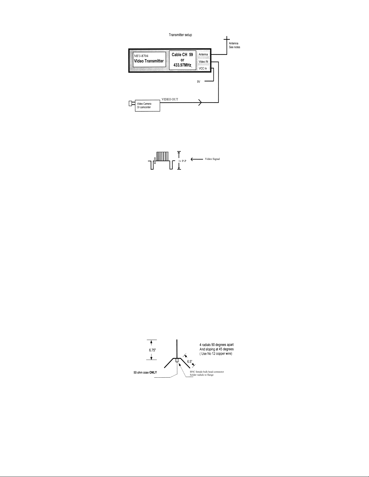
Video Input: NTSC or PAL composite video (1 V P-P) SMPTE STANDARD
NTSC 625 Line 60 Hz
PAL 625 Line 50 Hz
RF
Center frequency without modulation 433.97 MHz +/- 50Khz
Output level: +19dBmclean carrier
+16.5dBm modulated
Modulation type: High level amplitude modulation
Spurious output: 2nd harmonic better than 40dB down
VCC
Supply Voltage 9V DC (+/- 300mV)
Current draw 35 - 40 mA
The
MFJ-8704
A SAW oscillator is used in the fundamental operating mode to transmit at
uses the latest in MMIC technology.
The
MFJ-8704's
provides the best gain. If you plan to build your own antenna, an experimental antenna plan is included; however, commercially
available high gain antennas provide the best performance. Use the highest gain antenna possible for both the transmitter and receiver
with the shortest possib le transmission line.
is a high quality, high performance SAW stabilized video transmitter, using surface mount technology.
range can vary any where from 1/4 mile to 8 miles depending on the antenna used. A high gain yagi antenna usually
433.97 MHz (Cable channel 59)
. The power output stage
Operation and Setup
Video Input
The block diagram above shows the how the
standard video at 1 V P-P. Most consumer and commercial cameras and camcorders deliver SMPTE standard video, at the
connector. If for any reason you are not sure if the video device is delivering SMPTE standard video, you can confirm this by
out”
looking at the video signal on an oscilloscope.
MFJ-8704
needs to be connected to a video source. Make sure that you have SMPTE
“video
VCC Input
Due to size limitations there is no regulation provided inside the MFJ-8704. It operates on a 9V supply. While the MFJ-8704 may
tolerate about +/- 2V of VCC error, higher supply voltages may reduce the power output. A power supply could be substituted in
place of a battery. Use caution in providing the proper polarity. For battery operation, best results are obtained while using nickel
hydride or lithium 9V batteries. For extended operational time, you can parallel two 9V batteries.
include reverse polarity protection
power lead is (-) negative.
Antenna
The transmitting and receiving antenna are probably the most critical items for attaining best range. A small piece of 1/4 wave wire as
a transmitting antenna in combination with a high gain receiving antenna will work for short-range video transmission.
are obtained while using both high gain transmitting and receiving antennas.
Range testing was performed using the following antennas. The transmit antenna was a 14 element yagi, the receiving antenna was an
8 element yagi . At an approximate distant of 3/4 of a mile excellent picture quality was received. The receiver was a consumer grade
Sony TV tuned to Cable CH 59. Please remember, that while a cable ready television would suffice as a good receiver, a sensitive
ATV down-converter will far outperform any cable ready television.
Using a 1/4 wave ground plane (shown below) as a transmitting antenna and using a 14-element yagi antenna for the receiving
antenna, excellent picture quality at 1/2 mile is possible.
. Therefore be careful to not reverse polarity. The red power lead is (+) positive and the black
Caution: The MFJ-8704 does not
Best results
Experimental transmit / receive antenna
Some antenna performance characteristics
While some transmit-receive antennas combinations perform differently, the following chart depicts the theoretical system
performance of the MFJ-8704 using various combinations of antennas and an ATV down-converter.
 Loading...