


Table of Contents
Features ......................................................................................................................................1
Technical Specifications (Typical Unit): .................................................................................2
Receiver:.........................................................................................................................2
Transmitter: ....................................................................................................................2
Simplified Technical Description:............................................................................................3
MFJ-8631 Technical Description:............................................................................................3
General: ..........................................................................................................................3
Receiver:.........................................................................................................................3
Transmitter: ....................................................................................................................3
T/R Switching:................................................................................................................3
Connecting To Your MFJ-8631:..............................................................................................4
Power Supply:.................................................................................................................4
Antenna:..........................................................................................................................4
TNC Connection:............................................................................................................4
RFI:.................................................................................................................................4
Selecting Baud Rate: .................................................................................................................5
Receiver Filter:...............................................................................................................5
Transmitting: ..................................................................................................................5
Transmitter Deviation: .............................................................................................................5
Setting Deviation:...........................................................................................................5
Two-Way Deviation Monitoring:...................................................................................6
Confirming Deviation:....................................................................................................6
Ordering Crystals:.....................................................................................................................7
Receiver Crystal:............................................................................................................7
Transmitter Crystal:........................................................................................................7
Installing Crystals: ....................................................................................................................8
Crystal Oscillator Calibration: ................................................................................................9
Transmit Oscillator:........................................................................................................9
Receiver Oscillator:........................................................................................................9
More About 9600-Baud FSK Packet Signals:.........................................................................10
Sending And Receiving 9600-Baud Data: ...............................................................................10
In Case Of Difficulty:................................................................................................................11
1. Unable To Copy Off-Air Signals: ..............................................................................11
2. Unable To Connect:....................................................................................................11
3. Transmitter Erratic Or Inoperative:............................................................................11
Important Operator Notes: ......................................................................................................11
Appendix ....................................................................................................................................12
Technical Assistance......................................................................................................12
Replacing The Fuse Link................................................................................................12

MFJ-8631 Data Radio
MFJ-8631 220-MHz Packet Only
Congratulations on your choice of the MFJ-8631 Packet Only Data Radio. Please read this
manual thoroughly before attempting to operate your unit. Let's begin with a look at some useful
MFJ-8631 Features:
FEATURES
Packet-Only Performance
means you'll get uncompromising performance at all data rates--on AFSK or FSK--for a fraction
of what you'd pay for a converted voice radio.
Cool Running
it 24 hours a day, 365 days a year. It's perfect for unattended backbone links in your network.
Sensitive
throughput and fewer collisions.
Made-For-Data Filters
baud signals. No other radio does this!
Rugged 3-Watt Transmitter
without consuming needless energy.
Clean Unsquelched Data Output
rather than a speaker amp for flawless signal recovery.
Your TNC must have a DCD (Data Carrier Detect) circuit in order to work with radios
Note:
that have unsquelched AFSK output.
Lightning-Fast TXD
crystal control deliver ultra-fast switching.
Twin Modulators
mic-level signals at 1200 baud provide ultra-clean FSK and AFSK.
Simple Setup
Easy To Rechannel
crystals for the channel of your choice. Simple step-by-step instructions illustrate how to
exchange crystals and set them on-frequency with a counter.
The Right Tool For The Job
communication and nothing else! You can look forward to years of hands-off service.
: The MFJ-8631 draws only 25 mA on receive, and less than 1 A on transmit. Run
: Motorola-IC based receiver circuitry recovers data from weak signals for better
: Varactor-modulation for true-FM at 9600 baud and reactance modulation for
: The MFJ-8631 is compatible with virtually any DCD-equipped TNC-2 modem.
: Run your MFJ-8631 with supplied crystals on 223.7 MHz, or order custom
: The MFJ-8631 is designed from the ground up for packet. This
: Optimize your receiver for wide 9600-baud signals or narrow 1200-
: MRF-227 PA provides plenty of power to get the job done
: The MFJ-8631 uses a wide-response DC-coupled line driver
: Set TXD low! PIN-diode switching, continuous-running receiver, and
: Your MFJ-8631 was designed from scratch for fast, clean packet
Data Radio
1
MFJ-8631 Data Radio
TECHNICAL SPECIFICATIONS (Typical Unit):
Receiver:
Frequency Coverage........................216-230 MHz
Sensitivity....................................... 0.5 µV for 12 dB SINAD
Image Rejection..............................-45 dB or better
1st IF.............................................. 10.7 MHz
2nd IF............................................. 455 KHz
1st LO............................................ Crystal , 71`Mhz 3rd overtone
2nd LO........................................... 10.245 MHz
Selectivity........................................-6 dB at 20 KHz (data-passband filter)
AFSK Output.................................. 0dBm@ 3.0-KHz deviation
Current Drain..................................25 mA
Transmitter:
Frequency Control..........................Crystal, 18-MHz x 12
FSK/AFSK Input level.....................100 mV p-p @ 1200 baud, .5 V p-p @ 9600
Deviation........................................ 0-10 KHz, adjustable at TNC
RF Power Output............................>3 Watts into 50 Ohms
VSWR Tolerance............................3:1 Max.
Current Drain..................................1.0 Amp @ 13.8 Volts
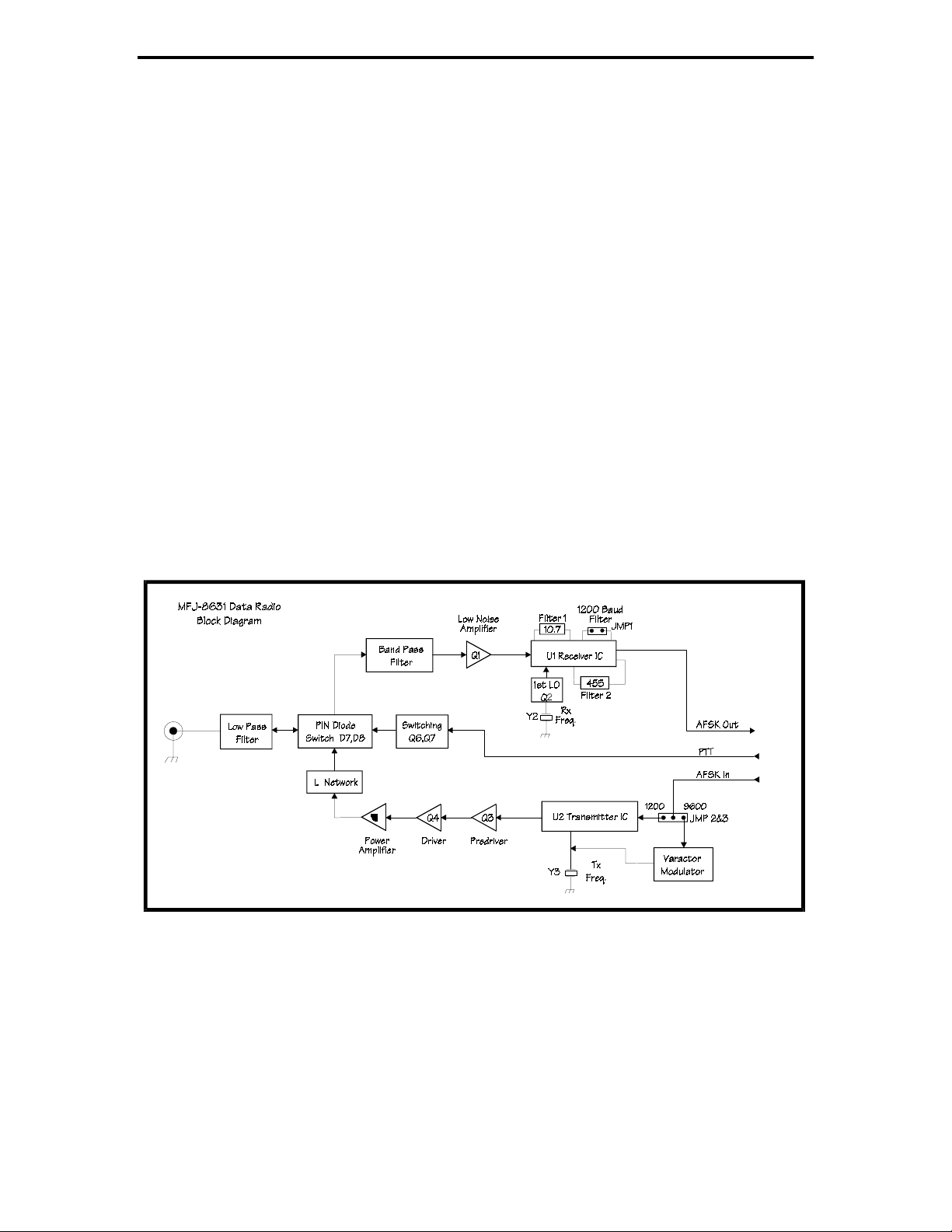
Figure 1
Block Diagram of MFJ-8631 Data Transceiver
2

MFJ-8631 Data Radio
SIMPLIFIED TECHNICAL DESCRIPTION:
Your MFJ-8631 was especially designed for packet-only operation. MFJ has eliminated costly
circuitry you don't need--things like squelch, repeater offsets, PL tones, DTMF pad, PLL
synthesis, memory, and the speaker-amplifier. At the same time, we engineered in essential
packet circuits like true-FM direct modulation, unsquelched AFSK, PIN-diode switching, datapassband IF filtering, and a tailored 0-Vu DC-coupled line driver to ensure top-notch
performance. There are no user-adjustable controls to set incorrectly, and the MFJ-8631 works
with most popular DCD-equipped TNCs.
MFJ-8631 TECHNICAL DESCRIPTION:
General:
The MFJ-8631 is a dedicated-channel 220-MHz FM-AFSK transceiver designed for use with
DCD equipped TNC-2 style modems at data-rates through 9600 baud.
Receiver:
Referring to Figure 1, incoming signals are preselected by the lowpass and bandpass filters.
Low-noise preamp Q1 enhances weak signal performance. U1 is a monolithic dual-conversion
narrowband-FM receiver IC that provides all mixer, IF amplification, limiting, and audio
functions. The 1st-LO, Q2, is an external 3rd-overtone oscillator-tripler and the 2nd LO is built
into U1. U1 and Q2 remain powered during transmit to ensure seamless RX recovery and selfmonitoring capability. IF passband filtering is provided by ceramic filters FL1 (10.7 MHz) and
FL2 (455 KHz). FL2 is a 20-KHz data-bandwidth filter which supports 9600 baud operation.
Discriminator output is looped to U1's auxiliary op-amp which is configured as a DC-coupled
AFSK line driver. Gain is set to provide 0-dBm AFSK output into a 600-Ohm load for
approximately 3.0 KHz deviation. A jumper configures the line driver feedback loop for HF
noise reduction at 1200 baud AFSK reception. Test points at the 1st-LO, RSSI, and DISC
outputs facilitate alignment.
Transmitter:
FM signals are generated by monolithic FM-transmitter IC U2. Frequency control is provided by
18-MHz crystal Y3 (oscillator/modulator output is multiplied by three successive stages to 220
MHz). 1200-baud AFSK is fed directly to the IC's reactance modulator. 9600-baud FSK is fed
through a varactor modulator for true-FM modulation. Pre-driver Q3 and Driver Q4 operate in
class AB and use tuned bifilar 4:1 interstage transformers to facilitate matching and bandpass
filtering. The PA stage (Q5) is a conventional class-C amplifier with a tuned-L network and pisection low-pass filter to provide Z-matching and harmonic suppression.
T/R Switching:
RF switching is executed by PIN diodes D8 (receive path) and D7 (transmit path). DC switching
is executed by Q6, Q7. Supply voltage to U1 is regulated at 5 volts, and voltage to U2 is
regulated at 8 Volts. The 1st-LO voltage is regulated at 6.8 Volts. Receiver chip U1 remains
powered during transmit for seamless T/R switching characteristic. MFJ-8631 is designed to
operate from 13.8-Volt @ 1-Amp.
3

MFJ-8631 Data Radio
CONNECTING TO YOUR MFJ-8631:
Power Supply:
The MFJ-8631 will operate from any well-filtered DC power source delivering 13.8 Volts at 1
Amp. The MFJ-4110 wall-adapter supply is a light-weight voltage-regulated unit especially
suited for powering the MFJ-8631. "CB" type supplies or battery packs capable of 1-A output
will also work (anticipate lower RF output when using a 12-volt source). The MJF-8631 accepts
a standard 5.5mm x 2.1mm coaxial-type power plug (Radio Shack 274-1569). Connect the (+) or
red lead to the center pin, and connect the (-) or black lead to the outer sleeve. Use a 2 amp
fastblow fuse with any power supply other than the MFJ-4110. Your MFJ-8631 features
"crowbar" protection to prevent damage from incorrect power supply polarity. If power leads are
accidentally reversed, the crowbar-diode conducts and immediately opens the radio's line fuse,
cutting off power (for line-fuse replacement instructions, see the Appendix).
Antenna:
For best packet performance, use a high-quality antenna adjusted for minimum VSWR at your
operating frequency. Omni-directional types--like the MFJ-1740 1/4-wave ground plane or MFJ1752 5/8-wave ground plane should provide good local coverage. For point-to-point
communication--especially at 9600-baud--install a directional yagi antenna. Be sure to feed it
with high-quality low-loss coax such as 9913, and keep the cable run as short as possible. In
many cases, a lower antenna fed with good cable will outperform a higher antenna fed with lossy
cable. To cut line losses to a minimum, avoid adding unnecessary in-line connectors, power
meters, and coax switches.
TNC Connection:
The MFJ-8631 plugs directly into any MFJ TNC starting with the MFJ-1270B. Any other DCD
equipped TNC, such as the PK-96 and many others, will also work with this data radio. Use a 5pin DIN-to-5-pin DIN cable, MFJ-5100, for connection to MFJ TNCs or the PK-96.
Caution
: Not All TNCs have DCD (Data Carrier Detect) circuitry, and your MFJ-8631 --which
has an unsquelched output---will not work with those TNCs.
Pin Function
1 AFSK IN (100 mV pp / 500 mV pp)
2 GND
3 PTT (ground or logic-low for TX activation)
4 AFSK OUT (2.2 V pp max into 600 Ohms)
5 N.C.
4
 Loading...