

MFJ-780 Instruction Manual
MFJ-780 DSP FILTER
Thank you for your purchase of the new MFJ-780 DSP Filter plug-in
board. The MFJ-780 is designed to provide Mark and Space filtering for
the MFJ-1278B and MFJ-1278BT Multi-Mode Data Controllers. The
MFJ-780 will also function very nicely when installed in the MFJ-1278 or
MFJ-1278T Multi-Mode Data Controllers too. The MFJ-780 uses state-ofthe-art Digital Signal Processing, or DSP technology. DSP technology
greatly improves signal clarity by reducing or eliminating noise, QRN and
interference, QRM. This will inturn improve weak signal copy in modes
such as CW and RTTY.
NOTE: If you have purchased the MFJ-1278B DSP unit, then the MFJ-
780 DSP Filter board is already installed.
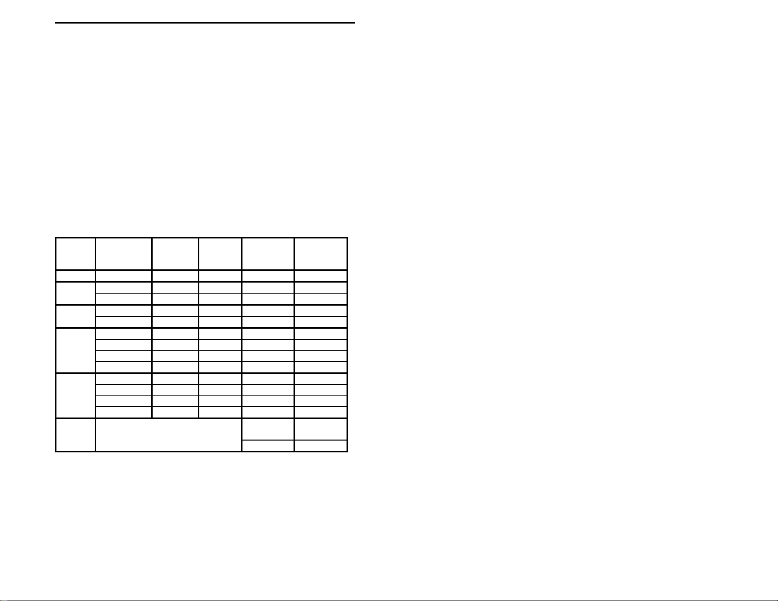
Modem
H
V
V*
C
M
*
All filters are of type FIR, Finite Impulse Response, linear phase with two
different choices: (1) 24 mSec delay time with an attenuation of 50 DB @ 60
Hz outside the bandpass or (2) 12 mSec delay time with an attenuation of 30
dB @ 60 Hz outside the bandpass.
Mark Tone
(Hz)
P
2125 2295 300 2210 504
1275 1445 300 1360 504
2125 2975 75 2975 246
2125 2975 300 2125 470
700 ------ ------ 700 100
700 ------ ------ 700 200
700 ------ ------ 700 500
1875 850
1200 2200 1200 1700 2400
2125 2295 75 2210 280
1275 1445 75 1360 280
2125 2975 75 2125 246
2125 2975 300 2975 470
700 ------ ------ 700 50
1100, 1200, 1300, and 1500 to2250
Space
Tone
(Hz)
in 50 Hz. Steps
Baud
Rate
(MAX)
Center
Freq. (Hz)
1200
NOTE: Modem V* and Modem M are dual-bandpass filters.
Bandwidth
(Hz)
300

MFJ-780 Instruction Manual
INTRODUCTION TO DSP
The MFJ-780 DSP uses "state-of-the-art" Digital Signal Processing or
DSP technology. Digital Signal Processing greatly improves signal clarity
by reducing or even eliminating noise, QRN, and interference, QRM. DSP
technology has existed for many years, but has always been very
complicated and expensive. Recent advances in integrated circuits have
greatly increased the processing power and reduced the size of DSP units.
These same advances also lowered the cost of DSP filtering, making DSP
technology more affordable for the average amateur or shortwave listener.
Almost any microprocessor can perform DSP, but only very fast or special
function processors perform DSP in real time. Therefore, the heart of any
DSP system is the digital signal processor. A digital signal processor is
similar to the CPU in a home computer, but its commands are tailored to
the type of instructions used in signal processing. The use of special DSP
commands allows a DSP filter function to be completed within a few clock
cycles, usually one, whereas a typical home computer CPU would require a
long set of instructions and therefore many clock cycles to perform the
same function. Analog Device's ADSP-2105, 16-bit processor is used in
the MFJ-780 design.
The MFJ-780 DSP Filter takes the "unprocessed" audio signals from your
receiver and converts them to digital information. This conversion is
achieved thr ough the sampling of the signal many thousands of ti mes per
second with an A-to-D converter. The result is a string of digital
"numbers" that represent the amplitude and frequency of the analog input
signal. The ADSP-2105 signal processor chip, then processes the resulting
information with different digital filtering algorithms depending on which
one the user selects via the MFJ-1278Bs MODE command. The end result
is a digitized signal with undesired signal components either reduced or
eliminated. The "processed" digital signal information is converted back
to an audio signal by the use of an digital-to-analog converter and sent back
to the MFJ-1278B demodulator circuits.
2

MFJ-780 Instruction Manual
INSTALLATION
If you have purchased the MFJ-1278B DSP unit, then the MFJ-780 DSP
Filter board is installed. This
to customers who have purchased MFJ-1278B DSP unit.
For those customers who have purchased the MFJ-1278B, not the MFJ1278B DSP unit, this is probably the most important section of this
instruction booklet. Performing the installation procedure precisely will
determine if you have a working or non-working inst allation when you are
finished. Please follow the steps below to ensure a good working
installation. In the below procedure we will refer to the MFJ-1278B,
however if you have an MFJ-1278BT, MFJ-1278, or an MFJ-1278T, the
procedure is still the same.
NOTE: If you have an MFJ-1278 or MFJ-1278T with an MFJ-56A, B, or
C Memory Expansion board installed, then you will have to make
a quick decision. You will either need to remove the MFJ-56A,
B, or C Memory Expansion board, or not use the MFJ-780 DSP
addition. The reason for this is that both the MFJ-56 and MFJ780 mount in the same place on the MFJ-1278 or MFJ-1278T
motherboard.
1. Remove all power connections and other cables from the MFJ-1278B.
2. Remove the top chassis cover from the MFJ-1278B by removing the
(4) screws from the sides of the c hassis cover.
3. If your MFJ-1278B has an MFJ-44, Plug-in Scope Tuning Adapter
installed, you will need to remove it too. To remove the MFJ-44, just
remove the hold-down screw with a small Phillips screwdriver and set
it aside. Holding the MFJ-44 firmly, gently pull up on the MFJ-44 PC
board, until it is unplugged from header, J15, on the MFJ-1278B
motherboard. Set the MFJ-44 PC board aside, you will re-install it
later.
4. Remove the MFJ-1278B PC board from it's chassis, and position the
PC board it in front of you so the LEDs are facing you. This step is
very important in order that the next step is done properly.
5. Locate C68, Point B in Figure 1, and desolder Capacitor Lead W1 of
C68 that is closest to the front panel of the MFJ-1278B and carefully
INSTALLATION
section does not apply
3

MFJ-780 Instruction Manual
remove the lead from the motherboard of the MFJ-1278B. Please refer
Figure 1 on page 12. DO NOT damage the solder pad that you are
desoldering Capacitor Lead W1 from; ensure that you desolder the
hole completely before trying to remove the capacitor lead.
6. Once Capacitor Lead W1 of C68 is desoldered and removed from the
motherboard, lay the capacitor down and bend the removed lead
straight up. This needs to be done right so that the next step can be
done properly.
7. Re-install the MFJ-1278B motherboard into the bottom chassis.
Position the bottom chassis so the LEDS on the MFJ-1278B are facing
you.
8. Secure the MFJ-1278B motherboard to the bottom chassis, by starting
the hold-down screws in the left and right-front and right rear corners
of the PC board. DO NOT tighten these screws down yet.
9. Start the threads of the 14mm aluminum hex spacer provided into the
hole in the left rear corner of the PC board. Be sure not to cross-
thread it.
10. Start the middle hold-down in the rear of the PC board, but DO NOT
tighten it yet. If you have an MFJ-44 to re-install, then start the
aluminum spacer that was removed earlier, but DO NOT tighten it
down yet.
11. Once you either have the hold-down screws or aluminum spacers
started in the proper PC board mounting holes, tighten them down
securely. DO NOT over-tighten this spacer as it is made out of
aluminum, thus you could strip the threads very easily.
12. Remove the 4052B IC from U32, located in front of the mounting hole
of step #4. Be careful not to bend or break any of the IC pins, as this
IC will be used later.
4

MFJ-780 Instruction Manual
13. Place the IC removed in step #12 into the IC socket on the MFJ-780
PC board labeled, U1. Be sure to align the notch of the IC with the
notch on the IC socket. The notch on the U1 socket is nearest the
inside edge of the MFJ-780 PC board. Please refer to Figure 3.
14. Align the pins of the extended socket, U1 on the MFJ-780 PC board
with IC socket, U32 on the MFJ-1278B motherboard. Also, be sure to
align the mounting hole on the MFJ-780 PC board with the 14mm hex
spacer.
15. Plug the MFJ-780 onto U32 on the MFJ-1278B motherboard, firmly
seating all extended socket pins into the U32 socket. Only firm
straight down pressure is needed to fully seat all extended socket pins.
16. Secure the MFJ-780 PC board with the screw that was removed from
the MFJ-1278B motherboard in Step # 3. DO NOT over-tighten this
screw, as the 14mm hex spacer that you are screwing it into is
aluminum, thus you could strip t he threads.
17. Locate the PC board mounting hole at MOUNTING HOLE A, just in
front of the radio DIN connectors on the MFJ-1278B motherboard,
and remove it. Please refer to Figure 1. Set this screw aside as it will
be used later.
18. Locate the 5" BLUE wire on the MFJ-780 at hole W2 and solder it to
Capacitor Lead W2 of C68. This needs to be made as short as
possible, in order to reduce any RFI from the microprocessor circuitry.
Please refer to Figure 2, C68 Exploded View on page 12. Make a
good clean solder joint by using only enough heat and solder to do the
job. Always remember that a "good solder" presents a smooth, shiny
appearance, where a "cold solder" joint will be dull and grayish in
appearance.
5

MFJ-780 Instruction Manual
19. Locate the 5" RED wire on the MFJ-780 at hole W1 and solder it to
Solder Pad W1. This connection needs to be made as short as
possible, in order to reduce any RFI from the microprocessor circuitry.
Please refer to Figure 2, C68 Exploded View on page 12. This is the
same solder pad that you removed Capacitor Lead W2 from earlier.
Make a good clean solder joint by using only enough he at and solder
to do the job. Always remember that a "good solder" presents a
smooth, shiny appearance, where a "cold solder" joint will be dull and
grayish in appearance.
20. Route the BLUE and RED wires neatly and out of the way, so they
DO NOT get pinched.
21. Ensure that all jumpers are set to the factory default positions
according the Jumper Settings table.
22. If you removed an MFJ-44, Plug-in Scope Tuning Adapter earlier,
then re-install it onto header, J15, on the MFJ-1278B motherboard.
23. You have finished with the installation of the MFJ-780 DSP PC board.
At this point it is best to go back and DOUBLE check all previous
steps in this installation procedure.
24. Put the top chassis cover back onto the MFJ-1278B and secure it with
the (4) screws you removed in step #2 of this instruction.
This will complete the installation section of the MFJ-780 PC into your
MFJ-1278B. You are now ready to use your new MFJ-780 DSP Filter, but
first you need to know a little about the onboard jumpers, and what they
have to do with the filter operation.
6
 Loading...