

MFJ MFJ-66 User Manual

MFJ-66 Dip Meter Adapter Instruction Manual
MFJ-66 Dip Meter Adapter
Thank you for purchasing the MFJ-66 Dip Meter Adapter. The MFJ-66 Dip Meter Adapter works with
your MFJ-209/ 249/2 59 S WR Anal yzer .
The MFJ-66 Dip Meter Adapter is a kit c on s istin g o f 2 co upli n g c oils a nd a U HF t o RC A f e male
adapter. The lar ger pro be coil covers 1.8 through 5 0 MHz, a nd offers maximum sensiti vit y i n t he 1 0 to
20 MHz range. The smaller probe coil covers 20 through 175 MHz, and offers maximum sensitivity in
the 100 to 150 MHz range.
Dip Meter Theory of Operation
The MFJ-66 Di p M eter a d apter is ver y ver s atil e. W hen p ro perl y us ed , i t can ma ke ac cu rate
measurements of many dif ferent R F circuit s. The foll owin g descript ion will hel p you get ma ximum
accuracy and versatilit y from the MFJ -66.
The MFJ-66 i s desi gn ed t o a da pt a SWR Anal yzer to work as a di p me ter . Yo ur SW R an al yzer
contains an i nter nal b an dswitc he d os cilla tor circuit. The oscil lator is buffered to i ncr eas e t he si gn al
level and pre vent t he lo ad fro m affe cti n g th e osc illat ors fr eq ue ncy. The hi gh le vel RF out put covers all
Ham bands below 170 MHz and is available on the ANTENNA jack.
The SWR Analyzer also con tains a meter used to measure t he unbala nce in an impedenc e b ridge
circuit. As the load on the ANT ENNA connec tor app roach es 50 oh ms resist ive, the meter read s a
lower amount (toward 1:1).
By connecting a small coil through the adapter to the ANTENNA connector, an SWR Analyzer can be
used to test e xterna l circ ui ts f or res onan ce. T he ma gnetic field surroundin g the coupling coil pro vid es
the required c onnec tio n or co u pling to th e circ uit u nd er t est . The meter on the S WR A nal yze r i s the n
used to measur e t he a mou nt of RF si gna l abs or bed b y the circ uit under test. T he meter r ea ds lo we r a s
resonance i s a ppr o ached .
Any resonant ci rcu it wil l a bsor b R F f rom th e coupling coil as lon g as th e c irc uit is tuned to the s a me
frequency as the oscillator in th e SW R Anal yze r . As the "Q" of t he circuit under test increases, the d ip
will become sharper and deeper. High "Q" circuits absorb more RF ener gy in a narrow ran ge of
frequencies. If t he "Q" of t he c irc uit un der t est is lo w or c oupli n g b et ween the c oupli n g c oil and the
inductor in the circ uit u nd er t est is i nad eq uat e, the dip shown on the meter will be s mall o r per ha ps n ot
even visible.
Unlike the tunin g coils of a conventional grid di p meter, th e M FJ -66 co upli n g c oil is n ot a part of a
resonant tank cir cuit. This adapter d epend s on t he " Q " of th e exte rna l circ uit to improve the
MFJ-66 Dip Meter Adapter Instruction Manual
y
circuit coupling. If the external circuit has a very low "Q", the coupling will have to be increased
by placing the inductor of the external circuit very close and in line with the axis of coupling
coil. This has the advantage that stray coupling is reduced and frequency pulling of the oscillator
is eliminated. Frequency readings can thus be made with more precision.
To insure accurate readings always keep the coupling as loose as possible while still getting a
readable dip.
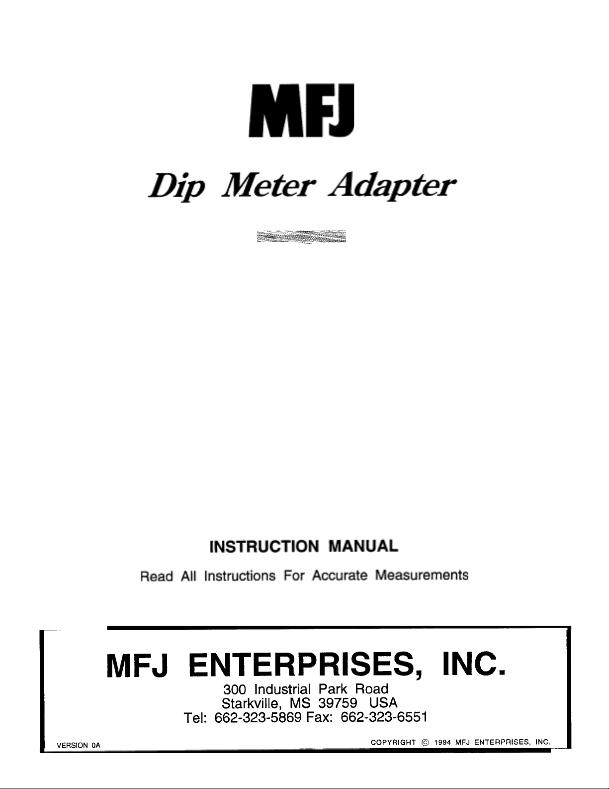
Maximum coupling is obtained when the coupling coil is either placed inside a larger coil under
test, placed against a coil of equal size or placed over a coil of small size. When using the
smaller coil to couple with a very small coil, such as a molded inductor, the outer plastic sleeve
must be removed or cut to allow the molded inductor to be inserted into the small coupling coil.
Otherwise coupling may be insufficient to create a dip.
Once a dip is found the coupling coil and the inductor of the circuit under test should be
separated until the dip is barely evident. The frequency should be read at this point for
maximum accurac
.
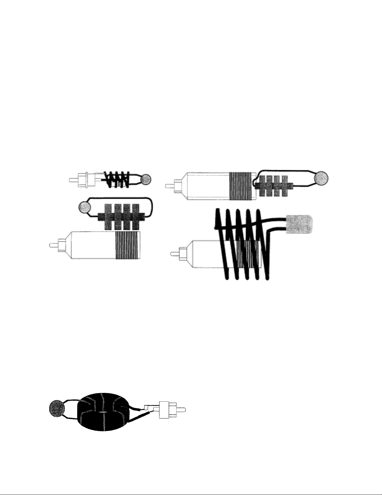
The coupling coil can be removed and the coupling coil jack can be used to directly feed a one
or two turn link coil on a toroidal inductor. The coupling can be easily varied when testing
resonant circuits containing toroids by adding or removing turns from the coupling link.
try to couple with the standard method of using a double link.
The air wound external link acts
Never
like a shorted turn on the toroid and lowers the inductance. This "shorted turn affect" will cause
inaccurate measurments for many types of toroids.
 Loading...