


MFJ ENTERPRISES, INC.
Model MFJ-1278
Multi-Mode Data Controller
Revision
SYSTEM MANUAL
Third Edition
9
1990
(c) Copyright 1990,
*****+*
This MFJ-1278 System Instruction Manual (Third Edition) is
for
If you have the MFJ-1278 with Revision
board and your MFJ-1278 has not been
aware that some features and information mentioned in
Instruction Manual may not apply to your MFJ-1278.
Pre-revision
Inc.
installable on certain board revisions.
MFJ-1278 with Revision 9 and later mother board.
for
upgrade information. Some new features may not be
Important Notice: Please Read
9
MFJ-1278 owners may contact MFJ Enterprises,
MFJ
Enterprises, Inc.
8
or
upgraded,
earlier mother
**+***
please be
this

TNC
2 SOFTWARE SOURCE
Copyright
Systek
CODE
(c)
and
1985
TNC
FIRMWARE
MFJ-1278 SOFTWARE SOURCE
Copyright
MFJ
Enterprises, Inc.
All
rights reserved.
or
Reproduction
translation
that permitted by Sections
States Copyright
express permission
Act
(or
of
the copyright owner
as noted below. Requests
of
107
its
for
further information should be addressed to
Inc.
The
carefully checked and
However,
MFJ
any product
P.
0.
Sox
494,
Yississippi State,
information contained in this document has been
is
believed to be entirely reliable.
no
responsibility
Enterprises,
Inc.
to
improve reliability, function
reserves the right to make changes to
without obligation to purchasers
MFJ
Enterprises, Inc. does not assume any liability arising
out of the application
or
use of any product
described herein; neither does
its
patent rights to others.
CODE
(c)
and FIRMWARE
1989
any part of this work beyond
or
108
of
the 1976 United
legal successor) without the
is
unlawful except
permission to copy
MFJ
Enterprises,
39762,
USA.
inaccuracies.
is
assumed
MIS
for
or
of
previous equipment.
or
it
convey any license under
or
for
design
circuit

TABLE
OF
CONTENTS
CHAPTER
Introduction
Acknowledgments
MFJ
Terminal Software Starter Packs
Serial Port Signals
Computer with Specific Serial Interfaces
Apple Macintosh
Commodore C64/Cl28
IBY PCjr
Radio Shack Color Computer
Radio Shack Model
IBM
PC/XT/AT and compatibles & other with RS-232C Port2-6
Other Computers with Nonstandard Serial Ports
Software Requirements Requirements
Apple Macintosh
Apple 11.
Commodore C64. C128
IBM PCjr
IBM PC/XT/AT & Compatibles
Radio Shack
Radio Shack Model
MFJ-1278 Serial Port Pin Functions
Computer Baud Rate
Autobaud
Changing Terminal Baud Rate
Verifying Serial Port Operation
Parallel Printer Port
Printer Port Connection
Printer Consideration
Printer Port Test
...........................................
........................................
CHAPTER 2 COMPUTER INTERFACING
....................................
.....................................
............................................
.....................................
II+.
IIe.
...........................................
Color
.....................................
............................................
I
INTRODUCTION
....................
...............
or
VIC-20
.........................
..........................
100
and NEC
8201
..................
.....................
IIc
..............................
or
VIC-20
.......................
.........................
Computer
100
and NEC
.........................
8201
..................
....................
by
SET
Menu
........................
.................................
............................
..............................
..................................
.......
2-10
2-10
2-10
2-10
2-11
2-12
2-12
.............
2-12
2-13
2-14
2-14
2-15
2-16
1-1
1-2
2-1
2-2
2-4
2-4
2-4
2-5
2-6
2-6
2-7
2-8
2-8
2-9
2-9
CHAPTER 3 RADIO INTERFACING
MFJ-1278 Radio Ports
Radio Ports Connection
Handheld Radio Connection
...................................
.................................
..............................
3-1
3-2
3-3
.
.

Radio Interfacing Methods
Method
Transmit Audio Level Adjustment (17
Setting the Receiver Audio Input Level
Method
Transmit Audio Level Adjustment
Receiver Audio Setting
Harmonics Interference
Monitor Speaker Connection
CW
Installation
DC
Key Paddle Connection
1:
Direct Connection to Micro hone and Speaker
2:
Accessory Jack
.......................................
Keying Connection
..............................
or
Interface
.............................
................................
............................
................................
...............................
(11)
..
................
.............
Box
Connection
..
................
3-10
3-11
3-11
3-12
3-12
3-12
3-4
3.4
3-5
3-6
3.7
3-9
CHAPTER 4 BASIC
First Steps
Basic Parameters Setup
Serial Port Configuration
Parity and Word Length
Ethos
New Lines and Line Wrapping
The MFJ-1278 Multi-Mode Modem
Operation Mode
Verifying Operation Status
Mode Switching with the MODE Command
Radio Port Switching
Memory Buffers
Loading Memory Buffers
Memory Buffers Transmitting
Buffer Serial Number
Memory Repeat & Buffer Repeat Time
Chaining the Memory Buffers
Tuning Indicator
Operation: Packet
Basic VHF Packet
A
Digipeating
Unsuccessful Connections
Monitoring Channel Activity
Your First Packet
Special Input Characters
Basic
HF Packet Operation Hints
Operation:
Receiving CW
Transmitting CW
Transmitting from Memory Buffers
CW Weighting
............................................
...............................................
.........................................
.........................................
......................................
.....................................
...................................
Connecting and Disconnecting Exercise
.....................................
Starting the
Digipeating
Monitoring on the Air
HF
Packet
CW
.........................................
QSO
..................................
....................................
.......................................
....................................
....................................
OPERATION:
..............................
..............................
..............................
.........................
..........................
..........................
................................
..............................
.........................
................................
......................
........................
QSO
...........................
.............................
........................
........................
.......................
ALL
MODES
................
..................
.........
.....................
................
4-1
4-2
4-2
4-3
4-3
4-4
4-5
4-6
4-6
4-6
4-8
4-8
4-8
4-8
4-9
4-9
4-10
4-10
4-12
4-12
4-12
4-14
4-15
4-16
4-17
4-18
4-19
4-19
4-20
4-23
4-24
4-25
4-27
4-28
4-29
4-29
iv

Radio Tune
Random Code Generator
Setting Up
Operation: CW Contest Memory Keyer
Sending CW with External Key Paddle
Operation: Modulated CW
Operation: Baudot
Setting
RTTY & ASCII Receiving
RTTY & ASCII Transmitting
Operation: AMTOH
Mode A "ARQ"
Mode A 'IARQ" setup
Mode A "ARQ" Operating
Mode A IrARQ1' Monitoring
Mode B "FEC"
Setup
Operating Mode
Mode S "SELCALL'I
AVTOR Status LED Indicators
Operation: Navtex
Navtex Stations and Frequencies
Navtes Operation
Operation: FAX
FAX Formats
FAX Frequency
FAX Operation Installation
FAX Printer Connection
Receiving FAX
FAX Printing to Printer
Display FAX on Computer Screen & Save to Disk
Two Levels FAX Pictures Format
Multi-level FAX Pictures Format
Terminating FAX Printing
Transmitting FAX
Two Levels FAX Transmitting
Multi-level FAX Transmitting
Creating FAX Pictures
Operation: SSTV
SSTV Formats
SSTV Installation
Printing Connection
Receiving
SSTV Printing to Printer
SSTV Printing to the Screen
Saving
Terminating SSTV Printing
Transmitting
Creating SSTV Pictures
.........................................
..............................
for
Code Practice
...............................
Up
for
ASCII and RTTY Operation
ASCII
........................
RTTY
&
.............................
..........................
......................................
.......................................
..............................
..........................
.........................
.......................................
for
Mode
B
................................
B
................................
...................................
........................
.....................................
...................................
........................................
.........................................
......................................
.........................
.............................
......................................
.........................
...................................
for
Transmitting
.......................................
.......................................
..................................
.............................
SSTV
Pictures
............................
........................
SSTV
Pictures
............................
.......................
SSTV
Pictures
.........................
.............................
....................
....................
................
............
....................
...............
..............
.....................
.....................
....................
.............
.....................
...
4-30
4-30
4-31
4-33
4-35
4-34
4-35
4-35
4-36
4-36
4-38
4-38
4-39
4-39
4-40
4-40
4-40
4-40
4-41
4-41
4-43
4-43
4-44
4-46
4-47
4-48
4-49
4-49
4-49
4-50
4-51
4-52
4-53
4-54
4-54
4-54
4-55
4-57
4-58
4-59
4-59
4-59
4-60
4-60
4-63
4-64
4-64
4-64
4-66
V

CHAPTER
5
ADVANCED
OPERATION : PACKET
Packet Special Characters
Packet Operating Modes
Command Mode
Entering Data-Transfer Nodes
Converse Mode
Transparent
Flow Control
XON/XOFF Flow Control
Hardware Flow Control
Type-in Flow Control
Detail
Detail HF Packet Operation
MFJ-1278 Host Mode
KISS
VHF Packet Operation
Station Identification
Automatic Operations
Unattended Operations
Packet Formatting
Commands Affecting Protocol
Packet Timing Functions
'Transmit Timing
Packet Timing
Radio Baud Rate
Special Protocol Times
Monitor Functions
Real-Time Clock and Time Stamping
Multi-Connect Guide
Setting the MFJ-1278
How
to
Easy-mail Mailbox
Setting Up
Mailbox Operation
Mailbox
Slotting and Acknowledgment Priority
Description
New
Parameters
Other Related Parameters
Initial
What to Expect
Packet Picture Transfer
Receiving Packet Picture on Printer
Using PKTPIX
Packet Pictures Transfer to the Computer Screen
Radio Setup
Operating
Interface for TCP/IP
........................................
.......................................
Mode
....................................
...........................................
..................................
...................................
..................................
Invoke Multi-Connect
Your
Messages
Easy-mail Mailbox
.....................................
..................................
Parameter
..................................
..................................
for
HF Packet
HF
Packet
&
TNC-2
.............................
.................................
........................
...............................
...............................
................................
...........................
.............................
...............................
..............................
........................
............................
.................................
.................................
..........................
................................
to
Normal Operation
.................................
...............................
................................
........................
Setting Summary
...........................
............................
..........................
................................
Mode
.......................
.............................
..................
........
.....................
...............
...............
...............
............
..
5-1
5-2
5-3
5-4
5-5
5-6
5-7
5-8
5-9
5-9
5-10
5-10
5-11
5-12
5-12
5-13
5-13
5-13
5-14
5-15
5-17
5-17
5-18
5-19
5-19
5-19
5-21
5-21
5-23
5-26
5-27
5-27
5-29
5-32
5-33
5-34
5-36
5-36
5-35
5-36
5-38
5-38
5-42
5-49
5-50
vi

CHAPTER 6 OPERATION COMMANDS
Entering Commands
Command Explanation
Command
Default
Commands
Packet Messages
Mailbox Messages
Command Mode
Link Status Messages
1278 Specifications
General Description
Detailed Circuit Description
Oscillator
Dividers
CPU
Serial Interface
Watch-dog
Modem
Power Supply
RS-232C Handshaking Protocol
Jumper Functions
Parallel Printer Port Pin Function . 512
External
Multi-Level Interface Connector
External Modem Interface Connector
Modem Disconnect . 54
HF
Tuning Indicator
List
Command Name
Parameters
............................................
and Baud-rate Generator
Complex
Timer
...............................................
1/0
Interface Port Pin Function
......................................
....................................
........................................
.....................................
..........................................
.......................................
CHAPTER 7 MESSAGES
........................................
....................................
Error
Messages
.........................
................................
CHAPTER 8 HARDWARE
....................................
....................................
...........................
..........................................
....................
.........................................
....................................
.....................................
........................................
...........................
.......................................
.
513
.................
.
514
.................................
...................................
..............
.
CNI
........
..............
6-1
6-2
6-2
6-2
6-2
6-2
6-5
7-1
7-2
7-3
7-5
8-1
8-2
8-3
8-3
8-3
8-4
8-4
8-5
8-6
8-6
8-7
8-8
8-10
8-10
8-11
8-11
8-12
8-15
CHAPTER 9 TROUBLESHOOTING
General
Step
Step 2: Obvious Problems
Step
Step
Specific Symptoms
Tests
1:
3:
4:
..........................................
Power Supply
Assembly Problems
Cabling Problems
......................................
...............................
...........................
..........................
...........................
vi
i
9-1
9-1
9-2
9-2
9-2
9-2

Symptom: MFJ-1278 appears dead
Oscillator and Reset Circuits
Digital Logic Lines
Symptom: Modem won't calibrate or key transmitter
Symptom: Uncopyable transmitted or received packet
Terminal Interface Troubleshooting
Symptom: MFJ-1278 won't sign on to the terminal
Symptom: MFJ-1278 appears to be signing
Symptom: MFJ-1278 signs on but won't accept commands
Symptom: MFJ-1278 appears
..............................
to
.....................
....................
.....................
on
but
have
"lock-up"
........
..
.
....
.....
9-3
9-3
9-3
9-4
9-4
9-5
9-5
9-6
9-6
9-6
CHAPTER
Explanation of Protocol
Physical Layer
Data Link Layer
HDLC Frames
AX.25 Level Two
Channel Use and Timing Functions
Channel Flow Control
Appendix
Appendix
Appendix C
Appendix D
Appendix
Appendix
Appendix
Appendix
...........................................
A
.
Hookup for Specific Radios
B
.
Modulator and Demodulator Calibration
.
Audio Output Adjustment
.
HF Radio Alignment
E
.
Converting to "Like-TNC
F
.
2400
G
.
Jumper Functions and Location
.
Command Summary
H
10
PACKET RADIO PROTOCOL
...............................
.....................................
....................................
.......................................
..................................
APPENDIXES
.....................
Packet Operation
........................
......................
.............
...
................
2"
.............
..................
..........
10-1
10-2
10-2
10-2
10-3
10-6
10-8
APX-1
APX-2
APX-17
APX-19
APX-21
APX-23
APX-25
APX-28
viii

Fig
.
Fig
.
Fig
.
Fig
.
Fig
.
Fig
.
Fig
.
Fig
.
Fig
.
Fig .
Fig
.
Fig
.
Fig
.
Fig
.
2.1
2.2A
2.2
2.3
3.1
3.2
3-
3-
3.5
3.6
3.7
E.1
E.2
(3.1
FIGURES
.
Serial port
.
TTL
port wiring
.
Serial port wiring for Radio Shack Color
Computers
Serial port wiring with jumpers
.
auxiliary signals
Radio Ports
.
.
Radio Port
HT
3
4
.
.
.
.
.
.
Special Keying Circuit
JMP L and
Method One Interconnect
Accessory Jack Interface
External Interface Box
Header U27
Header U28
Jumper Connector Location
wiring
for
Apple Macintosh
for
Vic.20. C64 and C128
...............................
.......................
1
and Radio Port 2 Connector
Cable
with Connector
...................
JMP
K
Location
....................
.....................
....................
......................
...............................
...............................
................
TABLES
......
....
for
....
.............
APX-21
APX-22
APX-27
2-4
2-5
2-6
2-7
3-1
3-2
3-3
3-3
3-4
3-7
3-8
Table 2.1
Table 2.2
Table 2.3
Table
Table 2.5
Table
Table 4.2
Table
Table
Table
Table 4.6
Table
Table
Table 4.9
Table 10.1
Table
2.4
4.1
4.3
4.4
4.5
4.7
4.8
A.1
Serial port signals required
.
.
Computers
instructions
.
MacTerm
.
.
.
.
.
.
.
.
.
.
.
.
MFJ-1278
RS-232C Pin Designations
Parallel Printer Port Pin Functions
Modem and Operation Modes
Tones & Shifts Produced by the MFJ-1278
Modem
Mode Command Codes and Baud
CW
Prosigns and Punctuations
NAVTEX
FAX
Formats
FAX
Station Frequencies
FAX/SSTV Multi-Gray Pixtones
SSTV Formats
AX.25 Control Codes
.
Hookup for Specific Radios
wii3
specific
serial
............................
option settings for operation
................................
......................................
Stations & Frequencies
...............................
..............................
.......................
by
interfacing
..................
..................
Rates
..............
.............
...................
..............
...............
MFJ-1278
with
.......
..........
...
2-11
2-15
4-26
4-43
4-47
4-48
4-57
4-59
APX-1
2-3
2-3
2-9
4-5
4-5
4-7
10-5
ix

MFJ-1278 Instruction
Manual
INTRODUCTION
INTRODUCTION
Welcome
Communications. By choosing the MFJ-1278, you have chosen
the most versatile and powerful Multi-mode Data Controller
manufactured for the Amateur Radio Service.
The MFJ-1278 interfaces your radio
computer that has an RS-232
terminal program.
work, WFJ recommends the
who have
computers. With an
terminal program
mode that
pictures.
This compact versatile controller employs the genuine TAPR
TNC 2 AX.25 protocol packet
tures
CW,
level board gives you
multi-gray level FAX and
1278
MFJ-12'78 also
The MFJ-12'78 also
Mailbox. This mailbox
messages
You also get MFJ's 20-segment,
Indicator that makes
that
indicator
modes of operation,
tuning methods for different modes.
to
IBM
to receive and transmit
ASCII,
lets
are
require precise tuning easy. This unique tuning
the exciting world
or
TTL level
While
or
compatible, Macintosh or Commodore C64/128
IBM
gives
lets
you transmit and
most communications programs
use
of MFJ Starter Pack for those
or
compatible computer, the MFJXFER
you a new Packet Picture Transfer
firmware
RTTY,
you monitor the new and growing NAVTEX system.
not limited
has
Facsimile,
the
a
Contest
gives
tuning
also
provides a uniform tuning method
so
you don't
VHF
and
ability
SSTV
to
pictures. In addition,
Memory Keyer mode.
you
the
has
soft-partitioned memory
a
certain number
for HF Packet and other modes
of
packet, HF packet, AMTOR,
SSTV.
to
Amateur
with
any personal
Serial
receive
plus many added
The new SSTV multi-
receive
EGA
and transmit
Digital
Port and
and
will
fea-
MFJ-
new Easy
10
Hz Precision Tuning
have
to remember different
Mail
of
Personal
characters.
for
CGA
all
a
so
In
addition,
has
ignore background noise while
a
features
installed. This new technology helps prevent many packet
collisions inherent in the current packet protocol.
A
as
device
been optimized for HF packet.
valid data
--
new
IC
the new MFJ Picture Perfect Digitizer
socket type
is
not designed specifically for your type computer.
the
advanced new
carrier.
Prioritized Acknowledgments and Slottime
New
1/0
Port
Chapter
DCD
circuit
It
still
"packet collision prevention''
lets
being able to respond to
you add peripherals such
I
Page
1
can
in
the MFJ-1278
be
adjusted to
--
even
if
are
the

MFJ-1278
You
also get a Key Paddle jack
as
an
memory buffers
function. In addition you also get contest serial numbering
and
a
A
speaker jack
transmit
received and transmitted by your MFJ-1278. Speaker output
also provides packet connect signal alarm.
A
Centronics compatible parallel printer port (DB-25)
you
printing received
Instruction Manual
Iambic Keyer
random code generator.
and receive audio and
are
lets
or
Memory Keyer. Ten user-programmable
provided
you plug in a speaker and monitor
so
for
you can
the
contest memory
CW
side
INTRODUCTION
use
your YFJ-1278
tone
as
keyer
it
is
lets
directly interface your printer to the MFJ-1278 for
text,
Packet,
FAX
and
SSTV
pictures.
Dual
once in any combination. Independent transmit audio output
adjustment
You
demodulator filter
The MFJ-1278T has a 2400 modem installed.
does not have the 2400 modem installed,
separately (MFJ-2400) and installed by the user.
2400
and 2400 packet. The only difference between
and the MFJ-1278T
installed.
Your MFJ-1278 package includes the following
1.
2.
3.
4.
5.
Radio Ports for
is
provided
also
modem installed, your MFJ-1278 can operate
One
One
Two Radio Port cables
One 8-pin connector the
One
get
MFJ-1278 Multi-Mode Data Controller
AC
adapter Power Supply
MFJ-1278 Instruction Manual.
a
HF
and
VHF
let
you connect 2 radios at
for
each radio port.
Threshold control for optimizing your
for different modes
is
that the MFJ-1278T has the 2400 modem
for
with
TTL
5-pin
port.
of
llOV
AC.
DIN
it
male
operation.
If
your MFJ-1278
can
be
300,
the
items:
connectors.
purchased
With
XFJ-1278
the
1200
6.
One
MFJ-1278 Fast-Start Manual.
Chapter
1
Page
2

MFJ-1278 Instruction
Manual
INTRODUCTION
ACKNOWLEDGMENTS
MFJ Enterprises, Inc. wishes to thank the following persons
who contributed to the development of the MFJ-1278:
Howard Goldstein, N2WX, who wrote the firmware for the
1278.
Jim
Criffith,
MFJ-1278 and his suggestions for improving HF packet and
RTTY
Eric Gustafson, N7CL, who helped make the MFJ-1278 modem
superior to all others. He also helped in documenting
sections
HF
Lyle Johnson, WA7GXD, who helped us with the MFJ-1278
schematic
Dan Morrison,
1278
Buck Rogers,
the new innovations and firmware for the MFJ-1278 and its
packet picture standard and make operation
mode in the MFJ-I278 more powerful and easier than ever.
contributions to the development of the MFJ-1278.
modes.
of
Packet operation.
.
CW
and Contest Memory Keyer modes the best ever.
supporting software.
Bob
Slomka,
Also
to countless unnamed others for their various
WA5RAX,
this instruction manual: Modem calibration and
KV'IB,
K4ABT,
WD4MNT,
for
his hours spent beta testing the
whose suggestions helped make the MFJ-
who has spent hours in beta testing all
whose software innovations establish the
of
every digital
MFJ-
Finally, to you, the user,
the air and furthering the cause of digital communication
ham radio. Our greatest thanks go to you!
Chapter
for
putting another MFJ-1278 on
1
P8gr
3
in

MFJ-1278
Inrtruotion Manual
COMPUTER INTERFACING
You
are
now ready to attach your MFJ-1278 to your station
or
computer
the
term
use to communicate with your MFJ-1278.
terminal. Throughout this manual
"computer" to
refer
to the computer
COMPUTER
INTERFACINO'
we
or
terminal you
will
use
The MFJ-1278 communicates with your computer through
serial
called RS-232C. Why
computer in production today either incorporates an RS-232C
style
available
manufacturer
In addition to the RS-232C port, the MFJ-1278 has
in
TTL
In order to use the MFJ-1278 with your computer, the
computer must have an RS-232C
port
program
emulator,
Since there
impractical for this chapter to provide detailed
instructions for each computer. Detailed information
given for some of the popular models
United States. Also provided
Information.
port using signals corresponding to
an
RS-232C interface? Nearly every
serial
as
TTL
port to allow interfacing with computers which need
signals such
and
a
will
port
an optional accessory, either from the computer
or
from a manufacturer of computer accessories.
program to support the
typically be called
or
communications program.
are
as
a
standard feature,
as
the Commodore
so
many computers on
C-64,
serial
serial
C-128
port,
a
the
or
modem, terminal
market
or
TTL
a
or
or
the VIC-20.
a
TTL
port. The
today,
available
is
general computer interfacing
standard
has one
a
built-
serial
in the
it
a
is
is
Chapter
2
Page
1

MFJ-1278
MFJ
Starter Packs
Instruction
Manual
COMPUTER
INTERFACINQ
MFJ Enterprises, Inc. offers
most popular computers.
terminal
program
and a
cable
your computer. The Starter Packs
a
Starter Pack
These
for
Starter
connecting
available
for
Packs
the
are
some of the
contain
a
MFJ-1278 to
as
follows:
MFJ-1282: Commodore VIC-20, C64, C128 in 5-1/4" diskette.
MFJ-1283: Commodore VIC-20, C64 in tape.
MFJ-1284:
MFJ-1284M:
MFJ-1287: Apple Macintosh, in 3-1/2"
Computer
If
you are using one
the cable provided to connect
computer. Follow the instruction manual provided
Starter
the MFJ-1278 to your computer.
1278 to your computer you can then proceed to
Baud
Rate"
IBM
IBM
Interface
Pack
to operate
section in
PC/XT/AT
&
clones in 5-1/4"
PC/XT/AT & clones in 3-1/2"
diskette.
with
of
MFJ
the
the
this
Starter Pack
MFJ
Starter
the
Pack, you should use
MFJ-1278 and your
terminal program and to connect
After
connecting
chapter to continue installing
diskette.
diskette.
the
with
the
the
MFJ-
"Computer
the MFJ-1278.
Computer
Interface
without
MFJ
Starter Pack
If
you
are
not using one of
the
MFJ Starter Packs then you
should follow the following instruction in
computer interfacing.
Serial
The
panel and
available
standard normal operation.
such
operations, you may want to
case,
Port Signals
serial
port connector on
is
at
this
as
binary
see
MFJ-1278
marked
your
*'SERIAL.'' There
MFJ-1278
connector. You won't need
For
file
transfer
Serial
some special applications,
or
use
more
Port Pin Functions in
are
some Bulletin Board
of
chapter.
The pins
-
must be
MFJ-1278
on the
connected
serial
are
connects to
port connector
shown in
a
computer exactly
Table
of
2-1. Note that the
as
this
is
chapter
on
the
for
rear
several signals
all
of
them.
them
In that
for
this
the MFJ-1278 that
if
the
MFJ-1278

MFJ-1278
Instruction
Manual
COMPUTER
INTERFACINO
were
used your computer
MFJ-1278 in the
ordinarily
If
fic
MFJ-1278 to your computer.
a
standard RS-232C modem.
use
Table
Pin Signal
2 Transmit Data Serial data
3
7
your computer
2-1. Serial port signals required by MFJ-1278.
Receive
Signal Ground The common ground for both
information in the following sections to connect your
Table 2-2. Computers with specific
Manufacturer
Apple Macintosh (tm)
Commodore VIC-20
I
BM
Radio Shack Color
NEC
with
to communicate with the modem.
is
a telephone modem, hook
same
Name
Data Serial data
listed in Table 2-2,
interfacing instructions.
way.
Mode
Apple II,II+,IIe,II-gs(tm)
C-64
C-128
PCjr,
most compatibles
1000,
1
Model
8201
(tm)
200,
If
Use
Description
computer
to your computer.
-
data
lines.
1
(tm)
(tm)
PC-XT,
Computer (tm)
IOOOHD,
2000,
100/102
you have successfully
whatever program
to
the MFJ-1278.
from
refer
it
up to the
from
the
to the speci-
your
MFJ-1278
serial
PC-AT
IOOOEX,
3000HL,
(tm)
and
clones
3000
IOOOSX,
you
Many computers require
cards incorporate the circuitry necessary to add
the
port to
are
Radio Shack computers, and the Sanyo
have one
If
should skip
your computer has a 25-pin RS-232C
section
Otherwise
dard Serial Ports.
-
the
you have another computer
computer. Some popular models in
Apple
of
on
refer
I1
series,
these computers with
to
one of the sections on "other computers.Il
Other Computers with 25-pin RS-232C
to the section Other Computers
a
serial
the
IBM
Chapter
2
port adapter card. These
Personal Computer,
MBC-55X
an
I1add-int1
we
haven't mentioned,
serial
Page
3
series.
serial
port,
an
this
refer
with
RS-232C
category
many
If
you
port,
or
you
If
to the
Ports.
Nonstan-

MFJ-1278 Instruction
Manual
COMPUTER INTERFACING
Some computers have no
cially available. Such computers
with the MFJ-1278.
Computer with Specific
Apple
The Macintosh
it
1278.
MFJ Enterprises, Inc. offers
the Macintosh.
Inc.
interface cable for connecting the MFJ-1278 to the Macintosh
and a terminal program. The Starter Pack for Macintosh
MFJ-1287.
a
Macintosh
will
or
cable
Mac
8
serial
work fine with the RS-232C
It
any MFJ dealer. The Starter Pack includes an
If
you wish to
wired
int
pin DB-25P DB-9P DB-25P
0s
as
h
shown in
serial
Serial
port
can be purchased from MFJ Enterprises,
port and no adapter
are
not suitable for use
is
commer-
Interfaces
is
an RS-422 compatible port, but
serial
an
optional Starter Pack for
port on your MFJ-
is
use
your own cable, you
Fig.
MFJ- 1278 Macintosh
2-1.
will
MFJ-
1278
need
Fig. 2-1. Serial port wiring for Apple Macintosh.
Note that pin
inside the Macintosh
serial
shield and connect pin
digital ground on the MFJ-1278
circuit
the
Commodore
The MFJ-1278 has
with the Commodore C64, C128
do not need a RS-232C converter to interface with the MFJ-
1278.
An
can
cable,
board pad
serial
connector.
C64,
optional Starter Pack for the
be purchased from MFJ Enterprises, Inc.
1
which
is
C128
a
of the DP-9P connector
or
the MFJ-1278.
we
recommend, connect both pin Is to the
1
of
the MFJ-1278
circuit
provided for this purpose near pin
and
VIC-20
built-in TTL-level port for interfacing
or
the VIC-20 computers.
C-64,
Chapter
2
Page
is
not connected
If
you use a shielded
serial
board.
C-128
connector to
A
or
the VIC-20
or
from
4
printed
1
You
any
of

MFJ-1278
Instruction Manual COMPUTER INTERFACING
MFJ
from
Commodore computer.
dealer.
the
The Starter Pack includes an interface
MFJ-1278
TTL
port to the
A
terminal program
user
1/0
is
port on the
also included.
To order, specify MFJ-1282 for software on disk
for software on tape.
If
you wish to construct your own cable,
as
follows:
MFJ-1278 Mnemonic
5-51,
Pin#
1
2
3
4
5
6
7
*C-128
++Pin
referred
Fig.
The
pin connections for
left
of
to right
these
RXD
DCD
GND
RT
S
TXD
DSR Data Set Ready
CTS
is
used in
E
is
not
to in
2-2A
this
TTL
as
you look
connections
terminal program.
connected. Programs
routines
will
probably use
Name
Receive
Data
Data
Carrier
Ground (Frame and Signal)
Ready To Send
Transmit
Clear
the
C-64 mode for
needed
Data
to Send
when using terminal program
chapter for
port wiring for VIC-20, C64 and C128
the
TTL
port
at
the
back
are
The
which
not necessarily
MFJ-1278 needs
utilize
RTS
and
Detected
the
file
the
information
these
connections.
Commodore computers.
(5-5)
of
are
the
MFJ-1278.
RXD,
numbered from
used
TXD
transfer and printer
CTS
as
well.
your software documentation.
cable
or
MFJ-1283
is
C-64
/
1
28+,
VIC-20 Pin#
B?C
H
N
E"*
M
L
K
All
by your
and
GND
Consult
-
IBM
PCjr
The
PCjr
interface; however,
uses standard RS-232C voltage levels
the
connector
used
is
not readily available from electronic supply
out information for
this
connector
is
given in
Technical Reference Manual.
IBM
Devices" for converting
RS-232C terminal connector. This
between
female
dealers
the
sell
the
MFJ-1278 and the PCjr.
inches long, however,
RS-232C extension cable,
"IBM
PCjr Adapter Cable for Serial
the
connector on PCjr to a standard
cable
so
you may want to obtain a male-to-
which
atsaches
It
is
should
available.
Chapter
2
Page
5
for
its
serial
non-standard and
dealers.
the
IBM
PinPCjr
directly
only about
be
readily
3

MFJ-1278
Radio Shack Color Computer
---
Instruction Manual COMPUTER INTERFACING
The Color Computer
Computer) uses
interface.
your MFJ-1278 to a Color Computer.
should be available from Radio Shack dealers.
Fig.
Radio Shack Model 100/102
---
These computers have built-in standard RS-232C
that are compatible with the MFJ-1278. You
standard male-to-male RS-232C extension cable to connect the
computer to the MFJ-1278.
-
IBM
PC/XT/AT compatibles Computer
"Include other computers with 25-pin RS-232 Ports1#
If
your computer
you should have a serial port
ctor.
cable
You
with
the correct gender on each end
a
Wire
Color Computer DB-25P
2-2.
may used a standard
series
4-pin DIN-style connector
a
cable as shown in Fig. 2-2 to interface
Serial port wiring
Color Computers.
is
a
IBM
(except
g&
NEC
PC/XT/AT
with
for
for
8201
or
standard DB-25 pin conne-
IBM
the Micro Color
for
All
a
PC/XT/AT
necessary parts
Radio Shack
compatible
of
its
serial
will
serial
the
cable.
need
or
serial
ports
a
clone,
modem
MFJ Enterprises, Inc. offers optional Starter
1284)
Starter
for
For other computers with a 25-pin RS-232C port, you should
consult your computer manual
which pins
which pin
manufacturer's recommendations
port to a modem. You may also find the technical information in this section
Your MFJ-1278
(DCE),
ters
this
able
for
the
IBM
PC/XT/AT
Pack
connecting your MFJ-1278.
the technical
are
is
to
simply
is
supplied with the computer connecting cable
it
uses
is
used
is
configured
the case
to send and
for
configured as Data Communications Equipment
for
wire
signal common. Follow the computer
useful.
term
for
as
Data
your computer, you
pin 2
of
Chapter 2 Page
or
compatible computers. The
or
accessory manual to
receive
for
an RS-232C modem. Most compu-
Terminal
the MFJ-1278 connector to pin
data on,
connecting the serial
Equipment
will
6
Pack
(MFJ-
see
as
well
(DTE).
probably be
as
If
2

MFJ-1278 Instruction Manual
of
your computer's RS-232C port, pin 3 to pin 3 and pin 7 to
pin
7.
You can provide these connections with a standard
wire male-to-female
depending on whether your computer has a DB25S
connector.
If
your computer is configured as DCE, you will have to wire
2
pin
and pin
1278.
pin
require that pin
connected to an appropriate signal. Others may require
connections
computer's output' signals on pins
of your MFJ-1278 to pin
2
of the computer connector to pin 3 of your MFJ-
Pin 7 of the computer connector will still connect to
7
of your MFJ-1278 serial port. Some computers may
for
or
5
of
uin
male-to-male RS-232C extension cable,
3
of
the computer serial port connector be
8
and Din
4
COMPUTER
INTERFACING
3-
or
DB25P
the computer connector,
20.
You can use the
and 6 as shown in Fig.
2-3.
MFJ-1278
RS-232~
Computer
2
3
7
4
5
6
8
4
Fig.
Other Computers
Computers with nonstandard serial ports must meet the fol-
lowing conditions.
First, the signal levels should be RS-232C compatible. The
MFJ-1278 requires that the voltage levels sent from the
computer be greater than about
less than about
$econd, the polarity of the signals must conform to the
232C standard. This means that the low voltage state must
correspond to a logical
logical
lr0l1.
2-3.
Serial port wiring with jumpers
auxiliary signals.
with
Nonstandard Serial Ports
+3
+1
volt in the other state.
lrlll
and the high voltage state to a
volts in one state and
for
RS-
Third, the computer must
signal which meets the RS-232C specification. The MFJ-1278
$upplies signals that meet this specification.
Chapter
be
able to correctly receive a
2
Page
7

MFJ-1278
Instruction Manual
COMPUTER INTERFACING
?lake
The computer serial port common pin must be tied to
1278
data from the computer
connector pin
data on must
or
buy a cable that provides the following connections.
serial
port connector pin
must
2.
be
tied
The
to
pin on
the
iqFJ-1278
7.
be
which
The
data
tied
line that sends
to
the
your computer receivgg
connector pin
the
MFJ-1278
3.
If your computer requires any other signals, you must
MFJ-
ar-
range to provide them. The documentation provided with your
computer
or
its
accessory serial port should clarify any
special requirements of your port.
Terminal Software Requirements
Any software package that enables your computer to
ASCII
with
used successfully with
familiar
MFJ-
terminal
your
1278.
with
NIPJ-12'78.
with,
an ordinary telephone modem should work
If
you have
a
telephone inodein and that you are
use
that program to communicate
3.
program that you have
If you are using a terminal program provided by
Starter Pack, proceed
in
this
chapter. Follow
to
the
"Computer Baud Rate" section
the
instruction provided by the
act
with
the
as an
your
YFJ
program.
Tf
you are not using a
with the instruction for your type
KFJ
terminal program, then proceed
of
computer.
Note: Some tarminal ?rograms (such
Serial
any
pin
Card)
characters.
1
and
2
of
requires
If
,JYP
1.
DCD
this
The
to
is
be
the
DCD
asserted
LED
case,
as
the
Apple
before they receive
place
on
a jumper across
the
front panel
function normally indicating received packets.
Apple
MFJ
terminal program and a
Macintosh.
such
Macint_o_sh_
Starter Pack for
If
as
MacTerm
you should want to use a terminal program
set
the options according to Table
the
Macintosh
cable
to connect the
Chapter
2
Page
(MFJ-1287)
MFJ-1278
8
11+
Super
will
includes a
to the
2-3.

MFJ-1278
Instructfon
Manual
COMPUTER
INTERFACING
Table
Apple
For
party
Pro,
1278.
MFJ-1278, but have not been tested.
Commodore C64,
The
be purchased from
dealer. Starter Pack includes an interface cable from the
NFJ-1278
computer.
specify MFJ-1282 for software on disk
software on tape.
II,
the
Hayes Smartcom
optional Starter Pack for the C-64, C-128 and VIC-20 can
2-3.
7
even parity
Handshake Xon/Xoff
modem connection
II+,
Apple
serial
There
TTL
MacTerm
Compatibility Termina
1200 baud
bits/character ANSI
t
e 1 e
p
hon e po
IIe,
I1
interface cards, you may
are
--
C128 and VIC-20
port to the
A
terminal program
option settings for operation
with MFJ-1278
1
VTI
00
UNDERLINE
us
80
Columns
r
t
ON
LINE
AUTOREPEAT
IIc
family
others which may be compatible with the
MFJ
of
computers with Apple
IIe
and Datacapture
Enterprises, Inc.
user
1/0
port on the commodore
is
also included. To order,
use
4.0
or
or
or
third-
ASCII Express
for
the MFJ-
from any
MFJ-1283 for
MFJ
If
you do not
BASIC communications program
Reference Guide published by Commodore.
listing
ASCII format internally.
MFJ-1278
computers.
NOTE:
"COMMODORE"
program. Also line
for
When using the above program, you
have
"true
at
300
key to shift to lower
the
MFJ
ASCII,"
baud
Starter
as
You
on
200
Pack
is
given in the Programmer's
these computers
will
the
probably want to run your
serial
case
should read
64:TP(J)=J:NEXT.
When making the connecting cable from
to
the
1/0
1278
the wiring information given on page
However, do not
port of the Commodore computer you may
use
pin E connection for this program.
Chapter
2
Page
then you may
Use
the program
use
port with these
must
before using this
first
For
TTL
port of the MFJ-
2-3
in this chapter.
use
a
modified
use
J=O
9
the
the
to
use

MFJ-1278 Inetruction Manual
IBM
PCjr
-
COMPUTER
INTERFACINO
The
cartridge. Start this program by typing
your PCjr BASIC manual
best
faster
-
IBM
The optional Starter Pack
the
prises, Inc.
includes
for
program allows you to receive FAX
display on the screen.
disk
stored
printers.
You may also use many commercial, "shareware'! and public-
domain terminal programs for
and clone computers. Special program written
radio and packet bulletin board service can also be used
with
not support printing of graphics to the computer
Radio Shack Color Computer
--~
IBM
results
PC/XT/AT
compatibles and clones can
connecting the
PCjr
than
a
for later viewing. You may also print any pictures
on
the
MFJ-1278.
has
a
built-in terminal program in the BASIC
TERM.
for
details on this program. For
with PCjr, do not run the
1200
graphics terminal program, and a connecting cable
disk to
baud.
and
Compatibles
or
from any
(NFJ-1284)
MFJ
MFJ-1278
It
will
an
EPSON
Note that
be
purchased from
dealer. This Starter Pack
to your computer.
also store
or
the
IBM
these
MFJ-1278
for the
or
SSTV
the
IBM
graphics compatible
PC/XT/AT, compatible
type
of
Refer
serial
IBM
programs
PC/XT/AT,
MFJ
pictures and
pictures on
for
Enter-
MFJ-1284
packet
screen.
to
port
will
There
Computer. You
gram (rather than writing your own)
has
Some of the terminal programs available
AUTOTERM and
XTERM
-~-
Radio Shack Model
These
Consult your computer's documentation
their use.
are
several
terminal
will
probably want to
programs available
use
since
a "software UART"
RICKEYTERM
for
0s-9.
computers have built-in terminal programs
that
100/102
is
(for
difficult to program in BASIC.
COCO
NEC
111).
8201
for
Chapter 2 Page
10
for
a
commercial
the
Color Computer
are
Others
the Color
COLORCOM
are
WIZ
in
instructions in
pro-
64,
and
ROM.

MFJ-1278 Instruction
Manual
COMPUTER INTERFACING
MFJ-1278
This
232C serial port connector.
special applications requiring hardware handshaking. This
information should not
Serial
section
Table
Pin
1
2
3
4
5
6
7
8
9
10
Frame
the
(computer
feedthrough on the MFJ-1278
serial
else
Transmit
attached device sends
Ground
MFJ-1278 and the chassis of the attached device
or
connector.
on
the
Data
Port Pin Functions
describes
2-4,
#
Mnemonic
TXD
RXD
RT
DSR
DCD
---
---
is
provided
terminal). This pin
MFJ-1278
It
is
an input line to the MFJ-1278 on
the pins used on the MFJ-1278 RS-
It
be
needed by most users.
RS-232C Pin Designations
FG
S
CTS
SG
Frame Ground
Transmit Data
Receive Data
Request To Send
Clear
Data Set Ready
Signal Ground
Data
+
-
for
attachment to the chassis
is
not electrically connected anywhere
circuit
data.
board.
is
intended
Name
To
Send
Carrier
12V unregulated reference
12V unregulated reference
is
PC
board near pin 1 of the
for
users with
Detect
brought out to
which
of
a
the
Receive
the
Request To Send
attached
Clear
attached
MFJ-1278.
Data
attached device that
Signal
between
Data
attached device
device requesting clearance
To Send
device
This
Set
Ground
the
is
an output line from the MFJ-1278 on which
is
is
an output from the MFJ-1278 signaling the
to send
line
Ready
MFJ-1278 and the attached
is
is
the common,
receives
an input line to
or
is
used for hardware flow control.
an output from the MFJ-1278 telling the
the
Chapter 2 Page
data.
refrain
MFJ-1278
or
the
MFJ-1278 which the
to
transmit.
from
is
return, path for all signals
sending
operational.
device.
11
data
to the

MFJ-1278 Inetcuctlon Manual
COMPUTER
INTERFACING
Data Carrier
normally configured,
It
is
true when an
1278
and another station;
exists. This configuration
Detect
AX.25
is
an output from the
DCD
reflects
the
connection
it
is
false when no connection
is
useful when the
MFJ-1278.
status of the
exists
between your
CON
MFJ-1278
As
LED:
MFJ-
is
used with a telephone style Bulletin Board system, since the
AX.25
telephone, indicates the presence of a user. Shorting pin
and
connection, analogous to
2
of
JMPI
on
the
MFJ-1278
a
board
modem signal on the
will
cause this output
1
to always be true.
Computer Baud
Rate
Autobaud
The
executed upon each power on of the
command
When
with the user's terminal baud
will
keyboard.
key on initial power up until the
AUTOBAUD
sets
is
user selectable.
AUTOBAUD
wait
its
until
User
baud
command routine installed in
MFJ-1278.
AUTOBAUD
is
ON,
it
MFJ-1278
detects
will
rate.
a
attempt to synchronize
Upon power
carriage return from the
the
MFJ-1278
is
defaulted to
on
AUTOBAUD
ON.
MFJ-1278
should repeatedly strike the carriage return
rate
to match the terminal baud
MFJ-1278
recognizes and
rate
of your
is
computer before signing on.
Once
the
iJIFJ-1278
If
AUTOBAUD
is
baud rate which
on without you having to strike the return key. In
AUTOBAUD
baud rate
to
match
of
your terminal program to match the baud
the
MFJ-1278
to
reset
will
will
restore
also
reset,
to
OFF,
is
the
new baud
the battery back-up
be
it
will
on after receiving
has signed on, user may
set
to
OFF, NFJ-1278
it
signed on to last,
will
set
AUTOBAUD
store the terminal
so
YFJ-1278
will
setting
you should
changed, then
rate.
or
you may remove
all
parameters to the default values.
reset
to
ON.
remember
MFJ-1278
that
will
no longer be able
if
the terminal
You must change the baud
rate
JMP
5
RAM.
When
on the
Once
MFJ-1278
MFJ-1278
reset,
is
powered
you
set
the
MFJ-1278
AUTOBAUD
on
attempt to match the new baud rate and sign
the
striking of
the
return key by the
OFF.
sign
rate
for
board
after
user.
Changing Terminal Baud Rate
After
the
MFJ-1278
is
signed on, you can change the
terminal baud rate by using the
SET,
display the SET
or
If
upon display of the
MENU.
9600
can
be
you change
selected
the
terminal baud rate
CMD:
A
baud rate of
command prompt.
from the
Chapter 2 Page 12
SET
SET
MENU.
300,
menu.
of
the
MFJ-1278
To
do this, type:
MFJ-1278
1200,
2400,
MFJ-1278,
will
4800
you

MFJ-1278
must also
MFJ-1278
AUTOBAUD
baud rate
on your terminal program.
terminal baud rate which you wish to operate your
on, you should
is
Instruction Manual COMPUTER INTERFACING
set
the terminal program baud rate to match
baud rate. Otherwise, upon each sign-on thru
turned
routine,
back
to whatever the terminal baud rate
OFF,
the
MFJ-1278
We
suggest that once you
set
AUTOBAUD command to
the
MFJ-1278
will
will
change
OFF.
its
Once
automatically sign-on
terminal
is
set
select
MFJ-1278
AUTOBAUD
without you having to press the "Return" key. This
important
when power
that if
rate does not match
once
until you
rate. Once
and
it
the
return key.
on
the
if
the
the
MFJ-12'78
will
main
power outage occurs, the
is
on again.
AUTOBAUD
reset
the
reset,
is
the
One
is
the
OFF.
MFJ-1278
turned
MFJ-1278
MFJ-12'78
important thing to remember
And terminal program baud
computer baud rate, then
off,
or
the
will
it
sign on upon power up and
The
PC
board
MFJ-1278
of
the
can be
XFJ-1278.
MFJ-12'78
will
not sign on again
will
sign-on
terminal program baud
default
with
reset
AUTOBAUD
a
few
to
strikes
by removing JYP
Verifying Serial Port Operation
the
the
to
a
is
is
ON
of
5
Now that you have a terminal program and
for connecting the
to
verify that
1.
Turn on your computer. Load and run the terminal
MFJ-1278
MFJ-1278
to your computer, you
will
communicate
program.
2.
Set
the
parameter
o
word length: 8 bits
o
o
o
o
3.
will
4.
Turn on your
be
If
duplex:
parity: none
stop
baud rate:
lit.
the
full
bit:
YFJ-12'18
program parameter, the
CON
(*)
time.
match
to execute
LEDs
or
will
extinguish.
other meaningless characters on the screen at this
This
the
is
because the
parameter
the
AUTOBAUD
of
the terminal program as
1
390,
1.145-1278.
1200,
2400,
4900
Note that
or
PWR,
terminal parameters match your terminal
MFJ-1278
of
your terminal program. You
will
If
not, you
NFJ-1278
sign on and
will
has not been
routine.
the
with
9600
STA and
hook-up cable
are
ready
your computer.
follow:
CON
LEDs
the
STA and
see
an asterik
set
will
need
to
Chapter 2 Page
13

MFJ-1278
5.
Execute the
few times in succession on your computer. The
execute the AUTOBAUD routine and set itself to the terminal
program parameter. Your computer screen will display the
sign-on message:
Instruction Manual COMPUTER INTERFACING.
AUTOBAUD
routine by pressing the
MFJ-1278
RETURN
will
key
+:J
bbRAM:LOAD WITH DEFAULTS
IA
MFJ
ENTERPRISES,
MODEL
AX.25 LEVEL 2 VERSION
RELEASE
CHECKSUM
cmd
MFJ-1278
XXXXX
XXX
:
INC.
(date)
2.0
-
32K
RAM
After sign-on the
extinguish.
If the sign-on message fails to appear, you should check the
connecting cable between and the computer and the
When you have successfully read the sign-on message from the
MFJ-1278,
type:
STA
and
CON
on the
MFJ-1278
MFJ-1278.
will
DISPLAY
followed by a carriage return. You should see a lengthy
list of items on your screen. This verifies the ability of
the
MFJ-1278
computer. Your serial interface
Printer Port Connection
The parallel printer port is located on the left side
MFJ-1278.
compatible parallel port.
end and a
end should be used. You may use a standard
printer cable instead of trying to wire your own.
cable
Centronics compatible printer
Enterprises, Inc. Model
for
to accept and respond
The printer port
A
36
pin Centronics male connector
connection
from
No.
the
is
is
now working.
is
configured for a Centronics
cable with male
MFJ-1278
is
available from
MFJ-12.
to
input
for
printer port to a
from
of
DB-25
the printer
IBM
on one
parallel
A
Printer
your
the
MFJ
If
you are using a terminal program which supports graphic
printing from the computer to the printer, then you should
connect the printer to the computer printer port and not to
2
Chapter
Page
14

MFJ-1278
the MFJ-1278 printer port.
If
your terminal program does not support graphic printing
to the computer screen and you want to print graphic:
Packet,
printer to the MFJ-1278 printer port. In this case the
printer must be either EPSON or IBM graph’ic compatible in
order
Instruction
SSTV
to
insure successful graphic receiving to the printer.
or
Manual
FAX pictures, then you should connect the
COMPUTER
INTERFACING
Table
IrIFJ-1278
Printer Port
Pin
Printer Consideration
The MFJ-1278 printer port will work with any printer that is
compatible with EPSON, IBM graphics. Printers which are not
EPSON
FAX
or
or
IBM
MFJ-1278 to print FAX and
2-5
Parallel Printer Port Pin Functions
DB-25
Name
#
Strobe
Data Bit
Data Bit
Date Bit
Data Bit
Data Bit
Data Bit
Data Bit
9
10
11
thru
12
thru
18
or
SSTV
graphics compatible printers which will allow the
17
25
IBM
graphics compatible may not be used to print
pictures. The following are some of the EPSON
Data Bit
Acknowledge
Busy
No connection
Ground
SSTV
pictures.
1
2
3
4
5
6
7
8
o
Canon PW-1156A
o
Citizen MPS-25
o
Epson FX-80, FX-85, LQ-800, MXIII, RX-80, FX-86e
o
Printer Plus
o
Seikosha IOOOA, 1200AI
o
Star Micronics- Gemeni
o
other printer: C. Itoh 8510P/NEC
If your printer
not listed, you may just try it to see if it will
printers have both EPSON and IBM graphics mode.
NLQ
is
EPSON
IOX,
NX-10, NX-1000
8023A
or
IBM graphics compatible and is
Chapter 2 Page
and compatible
15
work.
If
Some
your

MFJ-1278 Instruction Manual COMPUTER INTERFACING’
printer has both
EPSON
and IBM graphics mode, you should try
both modes to see which mode give you the best results.
In addition to being able to print weather FAX, FAX and
pictures, the printer connected to the
MFJ-1278
printer
SSTV
port
can also print incoming text in all modes as it is received
on the screen. This means that you can keep a log
your
9SOs.
To print text to the printer, you will
of
all
need to connect an IBM compatible parallel printer to
the
MFJ-1278
printer port. Printers without Epson
compatible graphics will not be able to print Weather FAX,
FAX
or
SSTV.
Printer Port Test
After properly connecting your printer to the
may
1.
--
verify its compatibility as follows:
MFJ-1278,
Turn on your computer. Load and run the terminal prog-
you
ram.
Turn on the
2.
NFJ-1278.
The
MFJ-1278
should sign-on with
the cmd: prompt sign.
3.
Type:
PRINTTES
If the printer
compatible, it will print a string
<CR>
is
connected correctly and
of
is
223
characters. Again this only shows that the printer
connected can print text. It does not necessarily
indicate that your printer can print graphics
or
IBM
unless it is Epson
graphics compatible.
4.
If the printer
compatible, then it should print
is
connected correctly and is
a
string
of
characters. Printing will start with ASCII SPACE
(value
32
decimal) and end with the value
255
decimal
which is not an ASCII character but may be a graphics
character.
5.
This completes the printer test.
Once the printer has completed the printing, the
1278
will return to cmd: prompt sign.
If
the printer test was
satisfactory, proceed to connect your radios to the
1278.
The above test is only valid
the
MFJ-1278
if
the printer is connected to the computer.
parallel port. This test can not be performed
Chapter
if
your printer is connected to
2
Page
16
223
MFJ-
MFJ-

MFJ-1278
Instruction
Manual
RADIO INTERFACING
RADIO INTERFACING
Computer interfacing, covered
only half
ing your MFJ-1278
MFJ-1278
Interfacing the MFJ-1278
the
following signals
pin outs
the
interfacing
to
your radios.
Radio
of
Ports
Radio Port 1 and Radio Port
task.
to
your radios involves connecting
at
Radio Port 1 and Radio Port
3-1.
Fin 1 Microphone audio,
transmitter.
2
Pin
Fin 3 Fush-to-talk, to
Pin
Pin 5 Squelch input (optional)
Ground, audio and
transmitter.
4
Receive audio, from your receiver to the MFJ-
1278.
to detect activity on
PTT
allow
in
the previous chapter,
The
from
other
the
half
2
are
MFJ-1278
shown in Fig.
common.
the
MFJ-1278 to key your
to
allow
a
shared-mode channel.
the
is
connect-
2.
to
MFJ-1278
is
The
your
Fig.3-I Radio Port
Chapter 3 Page
2
1
and
Radio Port 2 Connector
1

MFJ-1278
Instruction
Manual
RADIO INTERFACING
This
your
and transmit audio
connection should
stray audio and
should
able to operate on voice without disconnecting the
Radio
The two radio ports on the
and
connect two
Pin designation for Radio port 1 and Radio port 2 are the
same. See Fig.
MFJ-1278
radio port switching in the next chapter.
Use
to
radio cables
1278.
You may obtain the specific microphone connector pin
designation for your radio
Appendix
assignments
accuracy
verify
chapter describes how to connect these signals between
'IFJ-1278
set
and your radio and how to adjust the
levels
be
planned
RF
noise by
up your station
appropriately.
so
as
to minimize pickup
the
lines.
with
monitor speaker and be
If
possible, you
The
MFJ-1278.
receive
inter-
Ports Connection
as
Fig.
the
HF
radio
is
3-2
5
pin
A
of
this
to
be
HF
radios
done by using
to
wire a microphone connector (not provided)
DIN
if
at
the
for
this
information
-
d
connected at all
or
3-1.
cable provided. You
two radios are to be hooked up to the
end of
some
information
of
with
MFJ-1278
two
VHF
Switching
the
RADio
from
this
Instruction Manual
the
is
your radio manual.
\
allow both an
times.
radios to the radio ports.
of
the
radio ports
command,
will
the your radio's manual.
most popular radios. The
not guaranteed. You should
1-MIC.
AUDIO
2-GND
3-PTT
4-REC.
AUDIO
We
need to
FM
You can also
will
radio
on
discuss
wire
lists
of
the
two
HFJ-
pin
L
Two 5-pin
MFJ-12713
radio.
male
for wiring to the microphone connector
DIN
connector cables are provided with the
CHECK THIS CABLE WITH
BEFORE
WIRING
IT
TO THE
Chapter
AN
OHM METER
MIC
CONNECTOR
3
Page
TO
THAT
2
lector
for
your
IDENTIFY EACH WIRE
FITS
YOUR RADIOS.

MFJ-1278
Handheld Radio Connection
Some HTs key
current from
Radios
(tm)
Instruction
the
the
with
and Yaesu FT-x09, FT-x3, FT-727
this
Manual
transmitter by drawing a small amount of
microphone input pin (see Fig.
type
of
RADIO INTERFACING
special keying circuit
(tm)
and others.
3-3
are
below).
ICOM-2AT
Appendix
pin designation
instruction manual of your radio.
If
your
the microphone
remove
jumper at
Installing JMP
soldering
Rx"
shows the location
MFJ-1278 mother board, the
R140
find
installing
change
9e
are installed on
and
sure to remove JMP
to
1278
A
at
the
end of this instruction manual provided
for
some of the radios. Also consult
HT
has
this
the
cover of the MFJ-1278 and install
JVP
L
for Radio Port
I'Cx"
the
the
your radio
the
value of R140
another type of radio.
Push
and
rlRx'l resistor for Radio Port 2
JYP
L
To
Talk
like
K
or
clRx"
or
type
the
JMP L will
to the microphone cable. "Cx" and
the
of
JMP L and JMP K connectors.
still
JMP
K,
or
K
or
of
microphone input, you can
one shown in Fig.
1
MFJ-1278 mother board. Fig. 3-4
rlRxfl
would not key properly after
it
may be necessary for you to
R107
JMP
MFJ-1278
.-:-=-y;
Transmit Audio
4-l
I
C(X)
I
3-3
I
HT
Special Keying
Receive Audio
FIG.
3-3
or
you can
a
shorting
or
JMP K for Radio Port 2.
eliminating
resistor for Radio Port 1
to
a
smaller value.
L
when connecting
,-~
1
I
-
is
the
R107.
,
,-J
Mlcrophone
10
need of
On
If
the
Input
";::
-
Circuit
the
wire
the
is
you
MFJ-
FIG.
3-4
MFJ-1278 JMP L and
Chapter
3
Page
JMP
3
K
Location
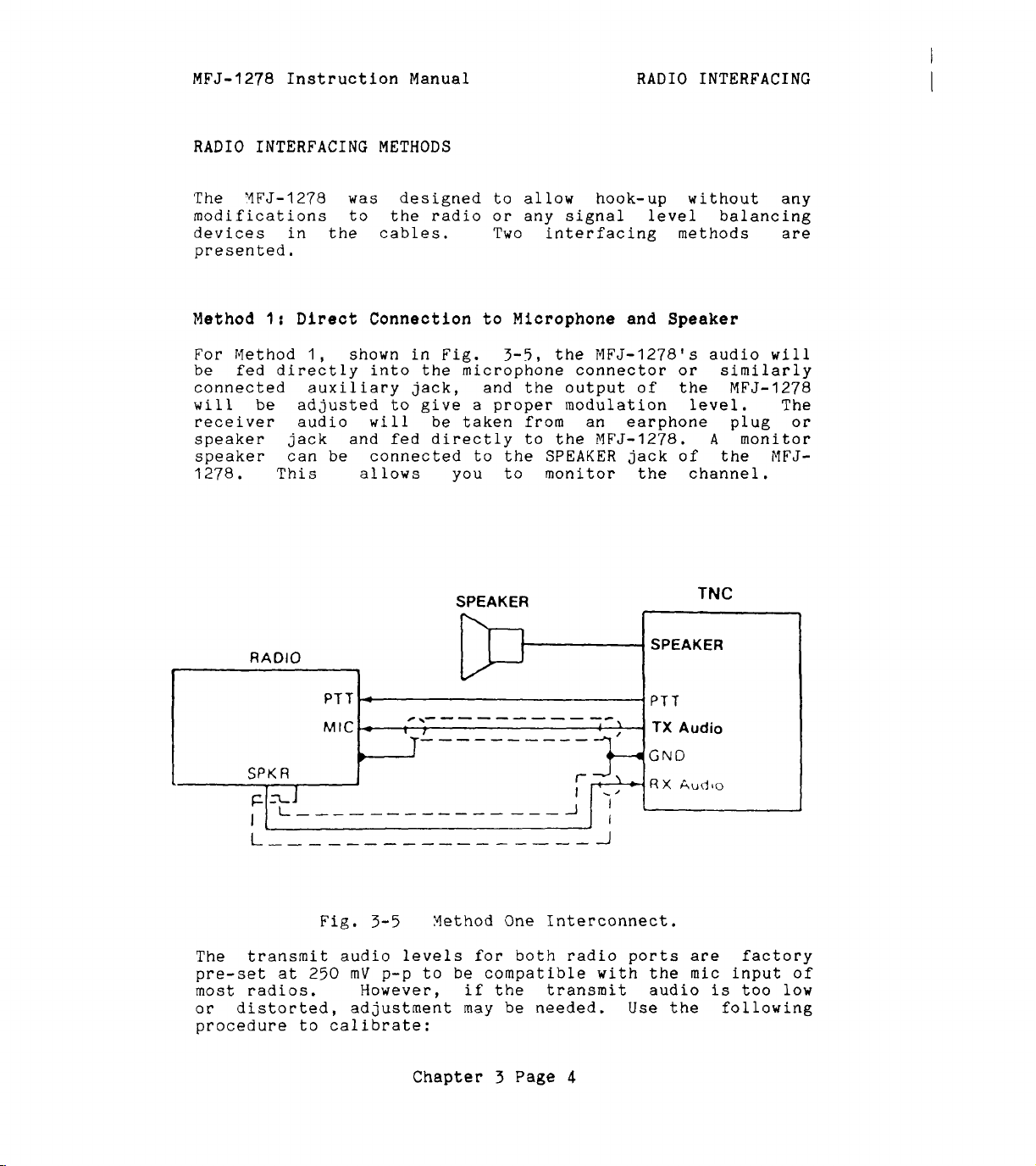
MFJ-1278 Instruction
Manual
RADIO
INTERFACING
RADIO
The
modifications to the radio
devices in
presented.
Method
For
be
connected auxiliary jack, and
will
receiver audio
speaker
speaker can
1278. This allows
INTERFACING
YFJ-1278
1:
Direct
Method
fed
be
1,
directly
adjusted
jack
METHODS
was
the
designed to allow hook-up without any
cables.
Connection
shown in Fig.
into
will
and
be
connected to the
the
to
give a proper modulation
be
fed
directly to
or
Two interfacing methods are
to
3-5,
microphone connector
taken from an earphone plug
you
to monitor the channel.
SPEAKER
any signal
Microphone and
the
MFJ-1278's audio
the
output
the
MFJ-1278.
SPEAKER
level
of
jack
balancing
Speaker
or
the
level.
A
of the NFJ-
TNC
will
similarly
MFJ-1278
monitor
The
or
RADIO
I
I
~
zi
FFJ
-
\-
- - -
- - -
-
-
--
__--------
GND
SPK
I
The
pre-set
most radios. However, if the transmit audio
or
procedure to calibrate:
R
1
transmit audio levels
at
distorted, adjustment may
Fig,
250
I
3-5
mV
p-p to
Hethod One Interconnect.
for
be
compatible with
Chapter
be
3
both
Page
1
radio
needed.
4
ports
Use
SPEAKEF
:Audio
are
the
mic
is
the
I
factory
input
too
following
of
low

MFJ-1278 Instruction
Manual
RADIO INTERFACING'
Transmit Audio Level Adjustment for Method I Interface
I.
--
Connect your
Turn on
the
MFJ-1278
MFJ-1278
-
-
and radio as shown in Fig.
and computer and
terminal program. Connect the radio to
and listen to the transmission
with
another nearby
start
a
dummy load
radio.
2.
Enter
the
modem calibration procedure by typing
CALIBRA
3.
and
board to key
until
the
transmitter
be
circuit.
will
mitter
watch-dog
With
transmitting
transmit audio level
screwdriver, adjust trimpot
for radio
er.
until
monitoring receiver.
a
carriage return. Press
the
transmitter, then tap
the
higher
K
key again
of
the
will
has
unkey the transmitter.
been keyed for
two tones
shut off automatically by
As
you perform the adjustments below, you
have
to periodically unkey then re-key
by typing
timer,
the
2)
Turn
the
no
increase in output level
the
K
key.
install a shorting jumper
MFJ-1278
the
higher
keying
of
the
as
follows.
(R157
while you listen to
adjustment on
the
the
K
key on your key-
the
space
is
heard.
After
a
few
seconds,
the
If
transmit watch-dog
the
you
wish
the
to
defeat
at
JMP4.
transmitter and
two tones, adjust
With
for
radio
the
monitoring receiv-
1
trimpot clockwise
is
heard
Pressing
it
a
or
at
3-5.
your
bar
the
will
trans-
the
the
small
R158
(CW)
the
the
4.
Rotate
until
the
reduced by
estimated
voltage
with
5.
Press
exit
if
have
mately
If
you notice a significant hum level in
in Step
shielded
an oscilloscope
the
the
you placed
now
the
3,
wire
audio circuit.
phone gain control, try reducing
adjustment on the trimpot counter-clockwise
audio signal
half
by
at
the
K
key to return to receive mode and type Q to
of
ear
or
transmitting audio pin
calibration routine.
it
to
set
your transmitter deviation to approxi-
on
the
monitoring receiver
the
maximum level.
This
accurately by measuring
of
the
or
A.C.
voltmeter.
Be
sure to remove
defeat
the watch-dog
correct level.
the
monitored audio
take measures to remove
it.
This may require
(recommended in any event) in your microphone
If
your transmitter
has
an adjustable micro-
the
sensitivity of
transmitter microphone circuit and increasing
level from the
MFJ-1278
to minimize hum
or
problems.
Chapter
3
Page
5
can
the
output
radio port
timer.
the
other
signal
noise
is
be
JMP4
You
the

MFJ-1278
Instruction Manual
RADIO
INTERFACING
Setting the
The
modem in your
phase coherence type data
threshold control and
can
be
used in combination to
level for
the
for
With
your radio
control
Receiver
Audio Input Level
MFJ-1278
the
modem and to optimize the
various methods
in
the
so
that
a steady
is
equipped
carrier
a
sensitive tuning indicator. These
set
the
of
operation.
receive
hiss
mode, open the squelch
is
heard on a speaker.
with
detector
an advanced
(DCD)
correct receive audio
DCD
characteristics
with
Set
the volume control to the minimum volume position. The
tuning indicator on
side
of
the
display and become stationary.
enough to disappear off
advance
the
point near
minimum audio
the
the
audio output level
tuning indicator "springs to
the
middle
level
volume control until
much audio present at the
estimated by
voltmeter.
for
degrade
NBFM
the
amplifier
ear
This
operation. Levels higher than this
modem performance
is
capable
the
of
MFJ-1278
the
end of the display. Slowly
the
display. This
should drift off to one
It
may drift
with
the
volume control until
life"
and dances around
is
the absolute
for marginal copy. Continue to advance
or
measured
will
be
there
receiver
near the correct amount of audio
is
with
approximately
output.
This
twice
can
an oscilloscope or
will
as
of
long as
producing the chosen output level
the
receiver audio
as
be
A.C.
not
without distortion (clipping).
While
the
1278
data
produce approximately a
when receiving unsquelched
still
DCD
listening to unsquelched
threshold control on
clockwise until the
carrier
indications. This control should be
the
DCD
LED
10%
duty cycle of
NBFM
receiver noise.
receiver
front panel
just
flickers
false
noise, rotate
of
your
with
DCD
MFJ-
false
set
to
activity
a
The
bandwidth
receivers
false
setting. In
modem sensitivity to false
of
the
audio coming out of
produce wideband audio which
DCD
activity regardless of
this
case,
set
the
DCD
will
DCD
threshold control to
be affected
the
will
the
threshold control
receiver. some
NOT produce any
maximum clockwise rotation. Modem performance
affected.
Chapter 3 Page
6
by
will
not be
the
its

MFJ-1278 Instruction Manual RADIO INTERFACING
Method
If
your
audio,
through
and receive
this
Acceseory Jack or Interface
radio
has
an accessory jack with
audio
signals, the interface can be done
jack (shown in Fig.
3-6).
Box
Connection
PTT,
TNC
transmit
2:
r------
MIC
Input
RCVR
Accessory
Jack
I
I
1
I
I
I
Jz
PTT
SW
Fig.
3-6
Accessory Jack Interface.
Chapter 3 Page
7

MFJ-1278
Instruction
Manual
RADIO
INTERFACING
If your radio does not have an accessory jack and you don't
wish to add a connector to your radio, you
separate external interface box. This
simultaneous connection
schematic of an external interface
of
your MFJ-1278 and a microphone.
box
is
may
box
shown
construct a
will permit
A
in Fig.
3-7.
An interface box similar to the one shown in Fig.
available
Regardless of whether you use an accessory jack
from
MFJ Enterprises, Inc. Model
No.
is
or
3-7
is
ME'J-1272.
an exter-
nal interface box, you should use shielded wire for all
signal-carrying leads. The connector types and pinouts will
be
determined by the connector jacks
EXT
SPU
A
on
your radio.
Fig.
3-7
External Interface
Chapter
3
Page
Box
8

MFJ-1278
If
you built the external interface box
follow this procedure to adjust
Instruction Manual
R(s).
RADIO
as
in Fig.3-7, then
INTERFACINO
1.
2.
Transmit
1.
Install
Temporarily solder a variable resistor'in place
Fig.
determined by experiment, but
cases.
microphone to the radio,
is
listen to
Adjust
Turn on the MFJ-1278 and computer and
terminal program. Enter the modem calibration procedure
by typing
Press
space
Pressing the
After
it
will
dog circuit.
will
transmitter by typing
the
watch-dog
JMP J on the MFJ-1278 PC board.
3-7.
Connect your MFJ-1278
being used. Connect the radio to a dummy load and
R(s)
-___
Audio Level Adjustment
The maximum value
or
the
transmission with another nearby radio.
for proper modulation
of
this resistor must
500K
to
to the interface box
for
Interface Method
should handle most
the radio. Connect the
as
follow:
start
CALIBRA
the
K
key to key the transmitter, then tap
bar
the transmitter has been keyed for
have
until the higher
R
key again
be
shut off automatically by the transmit watch-
As
you
perform the adjustments below, you
to
periodically unkey then re-key the
the
timer,
place a shorting jumper
of
will
K
key.
the
two tones
unkey the transmitter.
a
If
you
few
wish
is
to
at
of
R(s)
be
if
one
TI
your
the
heard.
seconds,
defeat
JMP4.
2.
With
transmitting the higher of
transmit audio level
3.
Adjust
modulation level (typically between
deviatio.
available, adjust
monitoring receiver
level.
determined by measuring the output voltage across
speaker with an oscilloscope
there
make adjustment
output level
radio port
audio output
mV
the MFJ-1278 keying
R(s)
is
p-p.
the variable resistor installed for proper
for
Amateur FM).
This
not adequate audio level from
can
of
of
the MFJ-1278 by adjusting
1
or
R158
of
both radio ports
Chapter
as
follows.
R(S)
is
be
estimated
R(s),
the
the
two tones, adjust the
If
FM
until the audio signal on the
reduced by half of
by
or
then you can increase the
transmitter and
3.0
and
test
ear
A.C.
equipment
the
or
accurately
voltmeter.
the
MFJ-1278 to
4.5
is
maximum
R157
for radio port 2. The transmitting
is
3
Page
factory
9
set
at
kHz
not
the
If
for
250

MFJ-1278
4.
Press the K key to return to receive mode and type Q to
exit the calibration routine. You have now
Instruction Manual
RADIO INTERFACING
set
transmitter deviation to approximately the correct
level.
5.
Carefully remove the variable resistor and measure
value. This
Remove
JMP4
is
if
you placed
the
proper value of
it
in Step
4.
R(S)
for your
particular radio.
6.
Select the nearest standard value fixed resistor
watt
R(S)
7.
If
that
3
adjustment with
controls,
is
fine) and permanently install this resistor
in the interface circuit.
you have access to
the
modulation
to
4.5
kHz
deviation.
R157
for
FM
level
the
Radio
MFJ-1278
1
test
is
If
or
equipment, check to
still
it
within the
is
not,
limits
make
transmit audio level
R158
of
Radio
2.
Receiver Audio Setting
a
your
its
(1/4
as
see
of
final
The
phase coherence type data
modem
in your
MFJ-1278
is
equipped with an advanced
carrier
detector
(DCD)
with
threshold control and a sensitive tuning indicator. These
can
be
level
used in combination to
for
the modem and to optimize
set
the
correct receive audio
the
DCD
characteristics
for the various methods of operation.
With your radio in the receive mode, open
so
control
that a steady hiss
is
heard on a speaker.
the
squelch
Set
the volume control to the minimum volume position. The
tuning indicator on
side
of the display and become stationary.
MFJ-1278
should
drift
off to one
It
may
drift
the
enough to disappear off the end of the display. Slowly
advance the audio output
the
point near
tuning indicator "springs to
the
middle
level
with the volume control until
life"
and dances around
of the display. This
is
the absolute
a
minimum audio level for marginal copy. Continue to advance
the volume control until there
much audio present at the
estimated by
voltmeter. This
for
NBFM
ear
or
measured with an oscilloscope
will
operation. Levels higher than this
receiver
be
near the correct amount
degrade the modem performance solong
is
amplifier
capable
of
producing
is
approximately
output. This can
as
the receiver audio
the
chosen output level
twice
or
A.C.
of
audio
will
as
be
not
without distortion (clipping).
While
the
1278
data
still
DCD
clockwise until the
carrier
listening to unsquelched receiver noise, rotate
threshold control on the front panel of your
DCD
LED
just flickers with
indications. This control should be
false
set
MFJ-
to
Chapter
3
Page
10

MFJ-1278
produce approximately
when receiving unsquelched NBFM
The
bandwidth
receivers produce wideband audio which
false
setting. In
maximum clockwise rotation. Modem performance
affected.
Instruction
modem sensitivity to
of
the
DCD
activity regardless
this
Manual
a
10%
audio coming out of the receiver. some
case,
set
RADIO
duty cycle of false
false
the
receiver
DCD
will
of
DCD
noise.
be affected by the
will
the threshold control
threshold control to
NOT produce any
INTERFACING
DCD
activity
its
will
not be
IMPORTANT
If
you experience interference from one of the harmonics of
the crystal oscillator in the MFJ-1278,
C47 (near the crystal) can be adjusted to move
the
of
Monitor
MFJ-1278 has a built audio amplifier to provide audio
external monitor speaker. Monitor speaker such
280
can be can be connected to the SPEAKER jack on
1278. Only one speaker
MFJ-1278
radio port in used.
If
wiring of a speaker plug
(1/8") mono
plug
and the
speaker
automatically
in use.
The
received and transmitted audio including
also used to provide a signal to the operator when
connection
MFJ-1278 to drive the
monitor speaker
board.
provide adequate volume you may use an external audio
amplifier.
NOTE:
harmonic.
Speaker
will
so
that
sleeve
is
speaker
is
If
Harmonic8
Interference
trimmer
capacitor,
the
frequency
Connection
as
the
is
needed for
automatically switch monitor speaker to the
is
necessary, use
or
stereo plug for this connection.
the
tip
of
the
plug
is
connected
needed for both radio ports. MFJ-1278
switch
jack
made.
the speaker to the correct radio port
on
the
MFJ-1278
A
small
audio amplifier
external
can
be adjusted by
the
internal amplifier
is
to
ground. Note that only one
speaker. Volume of the
RADIO
connected to the speaker
is
1
for monitoring of
CW
side tone.
is
R160
of
on
the
the MFJ-1278 does not
the
and
RADIO
a
3.5
Wire
a
built in the
MFJ-1278 main
for
an
MFJMFJ-
2.
mm
the
will
It
is
packet
You can
packet connect tone from the speaker monitor
a
trace
Appendix
disable
between the pins of
G
for the locations and functions of JMP jumpers.
received audio, transmitted audio
the
following jumpers. See
Chapter
3
Page
11
jack
or
the
by cutting

MFJ-1278
JMP
X
JMP
Y
JMP Z :
Instruction Manual
:
Transmitting Audio
:
Receiving Audio
Packet Connect Tone.
RADIO
INTERFACING
For example,
do not wish to hear the racket of packet, then you should
disconnect
disconnect
CW
Installation
Besides being able to send and receive
computer, the
you to connect an iambic paddle to the
MFJ-1278
Connect
-
DC
Connect
or
radio. The keying jacks of the
RCA
keying output and tube type radios should used the
BLOCK
use, try both outputs. The keyout outputs
are
constant key down
the
Keying Connection
DIRECT jack
phono plug. Solid
keying output.
protected.
if
you like to have the packet connect tone but
JMP
JMP
so
you can use
MFJ-1278
a
two conductor shielded cable from the
X
to disable the transmitted audio and
Y
for
received audio.
MFJ-1278
of
the
expands
the
for
CW
MFJ-1278
state
If
you are unsure
If
the wrong output
effect
on the transmitter.
CW
CW
operating fun by allowing
KEY
input
MFJ-1278
operation
to the keying input
radios should use the
as
a
as
MFJ-1278
keyer to send
follow:
accept a standard
of
is
used you
by using your
jack
of
the
CW.
GRID
of
BLOCK
your
DIRECT
GRID
which output to
of
the
MFJ-1278
will
notice
a
Key
Paddle Connection
The
USE
conductor fully shielded cable should be used.
tip of
plug
cable for
KEY
(1/8")
A
for
paddle input jack
stereo
MONO
the
the dot contact.
plug. (Radio Shack
plug, IT
plug
the
for
paddle ground contact.
of
the
MFJ-1278
Part
WILL
the dash contact and the
SHORT OUT THE
Be
sure to use the shield
Chapter 3 Page
12
No.
274-2641.
KEY
accepts
INPUT.
ring
a
3.5mm
DO
A
Wire
of the
of
NOT
two
the
the

MFJ-1278
Instruction
Manual
BASIC
GETTING STARTED
OPERATION:
ALL
MODES
'This
all
chapter
the
modes of
will
guide you through the basic operation on
the
MFJ-1278.
It
contains
information required to operate Packet,
AMTOR,
NAVTEX,
FAX,
SSTV and
CW
Memory Keyer.
First Steps
1. Make sure that your computer
232C port or
the
TTL
port on the MFJ-1278 according to
is
connected to
Chapter 2.
2.
Make
according to Chapter
3.
Turn on your computer. Load and run
sure
that
your radios
3.
are
connected to the MFJ-1278
ram.
4.
tlcmd:'t prompt sign.
the
the
Turn
on
the YFJ-1278. The MFJ-1278
If
the
MFJ-1278
return key on your computer a
NFJ-1278
+:J
will
sign-on as
as
fails
few
follow:
times
bbRAM:LOADED WITH DEFAULTS
IA
MFJ ENTERPRISES,
MODEL
AX.25
Release
Checksum
cmd
MFJ-1278
Level
:
2
XXXXX
XXX
INC.
Version
(date)
2.0
-
32K
RAM
the
basic
RTTY,
the
will
ASCII,
the
terminal prog-
sign on with
to sign-on, press
in succession,
CW,
RS-
Note:
tal
The
normally
The
letter
first
ttIAtt
from
five
see
may display
"Att
through
lines are
only when you power up the MFJ-1278.
Command Mode prompt cmd:
Command Mode and
sign-on
Before
the
the
MFJ-1278 can be fully operational, some of
basic parameters must
is
MFJ-1278
ready to accept your instructions. Upon
is
be
Chapter 4 Page
as
a
ttJ1l.
the
will
defaulted to the
vertical-bar and any capi-
sign-on message, which you
appear when the ME'J-1278
VHF
set.
1
will
The
is
in
packet mode.
the

MFJ-1278
Basic Parameters Setup
--
Instruction
------
Manual
BASIC
OPERATION: ALL
MODES
With
the
MFJ-1278
sign-on and default to
mode, you are now ready
you
defaults
changed!
Type
prompt.
for
Your
"address.
previous
will
use.
for
Let's
cmd:MYCALL
MYCALL
cmd
the
text,
Of
course, you should substitute your own
K5FLU.
call
sign
value
You may
now, but
try entering your call sign. Type:
K5FLU
was
:
MYCALL KSFLU, following
Don't
The
of
NOCALL
forget
will
the
be
IYFJ-1278
MYCALL
Command Mode prompt.
the
Y5
the
with:
FLU
the
command by
MFJ-1278
Vow try typing just
cmd:MYCALL
MFJ-1278
You can
the
command that
This
will
;4Y
see
verifies
respond
CALL
the
that
current value of most parameters by typing
sets
the
VHF
to
start setting up
be
satisfied
a
few
parameters
with
the
parameters
most of
will
have to
the
command mode
call
the
<CR>
at
the
end
of
the
used by the MFJ-1278
responds by telling you
parameter, and gives you a new
itself:
parameter followed by just a
accepted your
call
sign.
packet
the
sign
line.
as
its
the
<CR>.
be
The
configure
next
section describes
the
MFJ-1278
for
the
commands you
proper
text
particular computer. You may not use
unless you change computers
Serial
Port Configuration
This section describes
the
MFJ-12'78
to work best
Chapter
or
terminal programs.
the
commands you
with
your computer.
4
Page
2
will
use
display for your
these
commands again
will
use to
set
to
up

MFJ-1278
Instruction
Manual
BASIC
OPERATION:
ALL
Parity Word Length
If
you are using one of the optional starter packs by MFJ
Enterprises, Inc. then you should follow
the
instructions
given by the terminal program documentation
starter pack.
then you should
you are not using
use
the following instructions to
the
I4FJ starter pack
If
parity and word length for the MFJ-1278.
If
messages from the MFJ-1278 appear garbled,
incorrectly displayed
MFJ-1278's
that
the
value
bits
you have
baud rate needs to
is
as data, you may have to
may otherwise
characters.
8
serial
set
bits
To
and no parity.
be
characters,
you may need to change
port parity and word length.
the
baud rate correctly. See Chapter
be
changed.) The MFJ-1278's default
If
your computer receives
set
space parity,
interpreted
set
8
bits,
as
graphics
or
space parity, use
(We
since
other special
the
combination:
MODES
with
following
set
assume
the
the
with
the
2
if
8
text
AWLEN
PARITY
For
wordlength
AWLEN
PARITY
One of
are
terminal
these
more likely to require a different setting
rather
your terminal port
If
your computer requires odd parity,
computer
detects
AWLEN
PARITY
for shorter
AWLEN
PARITY
8
0
of
7
bits,
7
3
combinations
than a computer,
for
some special application.
framing errors, try setting
7
0
characters.
8
1
or
PARITY
(8-bit words)
(no parity bit)
even parity,
(7-bit words)
(
even parity
will
(7-bit
(no parity
satisfy most computers. You
or
if
words)
bit)
For longer characters,
(8-bit
words)
3
Echos
You may
ter
you type, for example:
see
two characters
on
your screen for every charac-
set
if
you have
you have configured
set
PARITY
1.
If
set:
a
your
Your
cmd
computer
:
RREESSEETT
is
echoing
Chapter
the
characters you type, and
4
Page
3
the

MFJ-1278
Instruction
Manual
BASIC OPERATION: ALL
MODES
MFJ-1278
FULL
is
also echoing
on
your terminal to stop the terminal from echoing
them.
In
this
case,
set
duplex to
characters to your screen.
New
Lines
__~____
If
everything displayed appears to
computer
displays a carriage return
the
MFJ-1278 from also adding an
equipment you may have to
1278's
The
width
<CR>
screen-width parameter
(or
been displayed on a line.
tically break long lines, you
width to
computer using
SCREENLN
lines, you should
the
FIFJ-1278.
and Line Wrapping
is
adding an extra linefeed (<LF>) whenever
automatic linefeeds.
of
many
<CR>
40.
CRT
displays.
<LF>
the
if
AUTOLF
width of your display. For example, for
a
TV
set
If your computer
set
SCREENLN
Otherwise,
be
double-spaced, your
(<CR>).
set
AUTOLF ON
is
set
The
MFJ-1278
is
ON)
If
your computer does not automa-
will
Set
AUTOLF
<LF>.
OFF
If
you change
to restore
by default to
when
80
need to
will
send an
characters
set
the screen
the
80,
for a display, you would
does
you
automatically break long
0
to
disable this feature on
will
get two
<CR>s
when the
to keep
extra
line wraps around.
A
few computers
a
line when several lines are typed in rapid succession, for
example, in
more
<CR>),
by
time
or
NULLS,
NULF
will
the
frequently lose
sign-on message. You can give
between lines by setting
ON
which
(delay
sets
after
<LF>).
a number of character-times for the
the
first
NUCR ON
The delay
characters of
the
computer
(delay
is
after
adjusted
delay.
it
MFJ-
the
have
a
set
With
the
basic parameters
set
up
which
enable
to be able to communicate with your computer,
discuss some basic functions and features of
Chapter
4
Page
4
the
the
MFJ-1278
we
can now
MFJ-1278.

MFJ-1278 Instruction Manual
The MFJ-1278 Multi-Mode Modem
BASIC
OPERATION:
ALL
MODES
The MFJ-1278 modem has five
components. These allows the MFJ-1278 to be used in
various modes
include
ASCII,
(including Weather
monitoring of NAVTEX.
Each
each mode of operation. Xodem re-calibration
for
the
The modes used with each modem
tqnes
4-2.
MODEM
...........................................................
VHF
HF
set
of
receiving
modes listed.
and
Table
I
P
H
V
I
I
I
of
operation. These modes
Packet, HF Packet, AMTOR, VHF RTTY,
ASCII,
modem components
shifts produced by each modem
4-1:
VHF Packet, 2 levels FAX
HF
AMTOR,
VHF
CW,
Yodulated
FAX),
SSTV
is
or
transmitting when switching among any
MFJ-12'78 Nodem and Operation Modes
OPERATION MODES
Packet,
RTTY,
HF
NAVTEX
VHF ASCII
Baudot RTTY, HF ASCII,
sets
CW,
with gray
independently calibrated for
are
shown in Table 4-1. The
of
pre-set modem
of
operation
HF
RTTY, VHF
CW
Memory Keyer, FAX
scales
is
not required
are
shown in Table
its
and
of
C
M
P
H
V
C
I
CW,
Vemory Keyer, Modulated
I
Multi-level FAX, Multi-level
I
2100
I
2319
I
29'75
I
850
I
1300
I
2110
I
2125
I I
I
----
Chapter 4 Page
5
I
I
I
I
CW
SSTV
800
200
850
----

MFJ-1278
Instruction Manual
BASIC
OPERATION:
ALL
MODES
Operation
Mode
Verifying Operation Status
Upon power up,
and
the
radio
port connection
operating status of
command
MODE
the
HFJ-1278
baud
rate
is
defaulted to radio
the
is
is
defaulted to
YFJ-1278
after the display of
operation mode, type:
MODE
'The
followed
'Iode Switching
Since
to familialize yourself
<CR>
YFJ-12'78
with
the
MFJ-1278
will
the
With
respond
cmd:
is
with
prompt.
the
MODE
Command
a multi-mode controller, you
with
the
one operating mode to another.
The
mode
operation mode and
modem to
can
command
MFJ-1278
of
operation.
be
be
used by
is:
provides an easily used command to change
The
MODE
select
used. Table
the
MODE
command allows you to enter any
a
4-3
command.
defaulted to
1.
at
any
the
CMD:
VHF
Packet
1200
baud. Radio
You can verify the
time
by using the
prompt.
To
modem status display lines
will
commands
desired
lists
The
for
changing from
radio baud rate and
the
valid codes which
format for
the
mode
check
need
the
MODE
MODE
Where
Table
the
xx,bbbb,m
xx
is
a
4-3,
bbbb
desired modem
specified then
the
Most of
baud
specify
selected
rate
HF
mode using
the
time,
and modem need not
R'r'rY
baud and using
you would type:
MODE
HB
Any of
the
other two.
baud
while
MODE
HB,110
<CR>
the
three
using
<CR>
2
letter
is
the
as
MFJ-1278
operation at the default baud rate
the
default narrow shift modem, for example,
parameters
for
RTTY
<
CR>
operation mode code
desired
listed
the
the
defaults
will
baud rate
in Table
select
modem
will
be
specified.
may
be
4-1.
the default modem
as
listed in Table
changed without affecting
example, to change
with
Chapter
the
same modem, you would type:
4
Page
6
or
speed,
If
be
sufficient
So
the
baud rate to
as
listed in
no modem
in order to
and
so
of
m
is
is
for
4-1.
the
45
110

MFJ-1278
Similarly, to select the wide shift modem without changing
either
Instruction Manual BASIC OPERATION: ALL MODES
the
operating mode or the baud rate you would type:
MODE HB,IIO,V <CR>
If you select an invalid code or baud rate, MFJ-1278
respond
?
BAD
cmd
:
Note that
to default settings.
On
CW,
selecting a baud rate you
entering
speed,
is
20
MODE OPERATION
CODE MODE
...........................................................
VP
HP
VB
HB
VA
HA
FX
CW
with
YCW
the
WPX.
Table
an error message:
with
a
the error message,
and Memory
number from 5 thru
last selection
4-3:
MODE
Keyer
Command Codes and Baud Rates.
operation modes, instead
will
99.
will
!DEFAULT
;BAUD RATE1 BAUD RATE/SPEED/FORMAT
I
I
VHF
I
HF
Packet
lVHF
Baudot
HF
Baudot
IVHE'
Ascrr
I
HF
ASCII RTTY
Packet
RTTYI
RT'l'Y
RTTY
1200
I
I
300
45
45 I
I
110
I
110
FAX /3(120L/M)I
I
CW/
Yem.
KeyerI
20
the
select
be
used.
I
1
300,
300
I
45,
150,
45,
150,
1
45,
150,
I
45,
150,
60,
360,
I
5
WPM
MFJ-12'78 has changed
CW
sending speed
If
you do not select a
The
default value
SELECTABLE
1200
50,
57,
75,
75,
75,
180,
WPM
100,
100,
100, 110,
100,
200,
50,
200,
50,
200,
50,
200,
90,
480
thru
300
57, 75,
300
57,
300
57,
300
120,
(Lines/Min.)
99
will
of
by
110,
110,
110,
240,
MC
TV
I
Modulated
SSTV
CW
AM I AYTOR/NAVTEX
Chapter 4 Page
i
1
I
20
!
(8.5s);
100
1
5
WPM
6.5,
100
12,
(
seconds)
7
thru
17,
99
WPY
24,
36

MFJ-1278 Instruction Manual BASIC OPERATION:
Radio Port Switching
ALL
MODES
MFJ-1278
Radio
1.
Upon
by typing
MFJ-1278
with
cmd:
provides two independent radio ports (iiadio 1 and
2).
Upon power up
the
cmd: command prompt, you can
"RAD
1"
or
will
display a new operation status and end
MFJ-1278
"RAD
2"
will
default
then press llReturntf.
prompt.
Memory Buffers
The
MFJ-1278
gives you ten user programmable memory
buffers. slemory buffer numbers are from
buffers
buffer
memory buffers can
Yemory buffers
Vemory Keyer
There
Memory buffer 0 can
memory buffer
'To
load
type
:
are
accessible by
is
capable
modes.
are
ten memory buffers provided by
9
the
memory buffer, under
can
is
of
storing up to
be
used
be
set
the
command
be
chained together in any order.
€or
RTTY,
repeated.
by
S'JFTIMZ.
the
BUF.
120
characters.
4SC11,
Time
CYD:
to
Radio port
select
0
thru
radio port
9.
Memory
Each memory
All
CW,
the
NCW
i4FJ-1278.
between repeats
command prompt,
ten
and
fGi
CMD:BUF#
Where
3.
to
Note: Notice
but
remember
the
buffer message.
--
Memo= buffers
Memory buffers can
command.
XXXXXXXXXXXXXXX......XXXXX
#
is
XXXXXXXXX....
120
characters.
__~__
If
the memory buffer number, from
that
..XXXX
there
is
is
the
NO
space between
to put a space between
Transmitting
be
transnitted by using
RUFKEY
is
left with
<CR>
buffer message of up
the
the
default value
(TAB key), user can transmit any buffer
the
Once
to receive mode.
back
rrTAB"
the
key followed
buffer message
to receive.
with
is
User
do not have to type
Chapter
a buffer number
transmitted,
4
Page
YFJ-1278
8
0
thru
"BUFtl
and
"Q"
buffer number and
the
BUFKEY
of
'lgll
(0-9)
by pressing
(0
thru
will
"C'I'RL-R"
revert
to
9).
go

MFJ-1278
Instruction Manual
BASIC
OPERATION:
ALL
MODES
BUFKEY
for
press
transmit and you
1278
If you are using
can only
RTTY
a
to
the
be
used in the
CW/MCW
mode.
It
or ASCII modes. For RTTY and ASCII modes you
"CTRL-TI'
and a buffer number to initiate a buffer
will
press
a
"CTRL-R"
to revert the
receive mode.
the
MFJ-1278
with
MFJCOM,
program, you must change the BUFKEY value of
to
II
',
I1
(
$5C
1
key.
euffer Serial Number
If
will
Suffer
the
serial number counter value
a maximum
If for any reason
return to
I_--
the
memory buffer
replace
is
------
text
the
transmitted. The number
#
serial number counter,
of
the
65535,
CMD:
where
the
serial number must
command prompt and enter
includes a
with
a
SERIALNO.
is
the
counter
tf
sign, the
number
is
each
the
current value of
Once used,
incremented by one up to
rolls
be
changed, you may
the
number by typing:
CMD:SERIALNO
Where
to
65535.
#####
I?$'##+
<CR>
is
the
desired serial number from
is
not valid
will
MFJ-
IBM
terminal
"TAB"
YFJ-12'78
time
(3)
key
that
this
over to zero.
new serial
0
--
"iemory
-
kpe_a_t_
The buffer 0 repeat
followed by a number from 0 to
gpd_
Ruffer
time
Re_ee&
is
set
Time
by using
65535
seconds. BUFTIME of
seconds represents no repeat after Ecuffer
RUF'rIIflE
RUFTIqE
RIIFTTl?E
This
then you must
example, if you want
message and
5
add
19
seconds, then you must
is
usable in
is
not effective
is
the
TOTAL
means that
set
the
seconds to
CW,
YCW
and Yemory Keyer modes.
for
memory buffers
time
if
your buffer message
the
a
for one cycle of Buffer 0 message.
BUFTIME
5
second delay between
longer than ten seconds. For
beginning of message to be repeated, then
the
total message
set
BUFTIME
time.
for
second delay.
If your buffer
Memory Buffer
0
message
0
to repeat every
is
10
seconds long, and you want
5
seconds, under
command prompt, type:
CYD:BUFTIME
15
<CR>
Chapter
4
Page
9
the
is
command
0
is
transmitted.
1
thru
9.
10
seconds long,
the
end of
If
your message
15
seconds for a
R'JF'l'IME
0
the
is
5
CMD:

MFJ-1278
Instruction
Manual
BASIC
OPERATION: ALL
MODES
Yemory buffer
memory buffer
If
EUFT1,qE
will
receive mode between repeats. This allows you to
monitor the frequency.
during the pre-set delay
repeat until buffer
ChaininA the Kemory
___
All
while
memory buffer
together in one transmission.
program the message in memory buffers as follows:
From
CYD:BUFO
CY3:
CWC:BUF5
automatically release the
-
-_-
ten memory
being transmitted.
CYD:
BUF2
dhere
program into the memory buffers.
command prompt, type:
XXXXXXXXXXX....XXXXX
XXXXXXXXXXX.
XXXXXXXXXXX..
0
9
from repeating,
is
-
-I
buffers
3,
XXXX
will
set
0
Buffers
- - -
nenory buffer 2 and memory buffer
is
repeat every 5 seconds.
set
BUFTIME
to a nonzero value, the
PTT
line and revert to the
If
the
YFJ-1278
time,
is
interrupted.
-
-_
-
may
be
For
CTRL-T
. . .
XXXXX
.
.
XXXXX
the desired
CTRL-T
<CR>
chained together in any order
example, you may transmit
To
it
achieve this, you should
2
<CR>
5
<CR>
text
TO
0.
is
not interrupted
will
you wish to
continuously
To
stop
NFJ-1278
5
In
transmitted,
then Suffer
0,
to
Vote: If
automatically
mode between repeats. This allows you to monitor the
frequency. If the
pre-set delay
3
Tuning Indicator
Your
is
for tuning to signals for optimum reception but also
filter
the example shown above, whenever Suffer
the
5.
Buffer 2 and Buffer 5 repeatedly, then add
the end
of
the
RJFTTME
release
time,
is
interrupted.
MFJ-1278
sensitive, very accurate and extremely useful not only
MFJ-1Lld
If
you want the
Buffer
5
is
a non-zero value,
the
P’i’l
i*IFJ-1278
it
will
is
equipped with a tuning indicator which
will also transmit Suffer
YFJ-1278
content.
to
transmit Buffer
a
MFJ-1278
line and revert to the receive
is
not interrupted during the
continuously repeat until buffer
3
“C’I’RL-‘I‘
will
for
alignment and audio
Chapter
level
4
indication.
Page
10
is
2,
0”

MF
J-
1
278
I
ns
t
r
uc t ion Manual
BASIC
OPERATION:
ALL
MODES
The
for
position
of
the
tuning indicator
tuning a signal under the following conditions:
1.
The
station
is
transmitting data (both tones
a single carrier).
2.
The
within
3.
There
for
Assuming that
station
the
receiver frequency
centered in
represent
be
used.
The
use
CCD
LED
the
capture range of the
is
sufficient audio output from
proper operation
the
conditions above are
with
of
the
tuning indicator
the
display. Actually there
the
center
the
tuning indicator
is
lit
indicating that
of
so
that
of
the display.
later in each mode of operation.
LED
is
only meaningful
the
PLL
demodulator.
the demodulator.
met,
is
quite simple. Just
the
tuning indicator
are
Either
will
be further discussed
NOT
just
the
signal
receiver
is
tuning in a
set
2
LEDs
or
both may
LED
is
which
Chapter
4
Page
11

MFJ-1278 Instruction Manual BASIC OPERATION: ALL MODES
OPERATION:
VHF
Packet
If you
learn quite
actually transmitting anything.
the
hlFJ-1278
bezone
If you
you may not
the other nodes .sf operation
!)isconnect your radio from the
Y?<J-12{5.
analog loopback
Ccnnect your computer
cable. Lurn
p r og
r
an,
Faacket radio
sets
insures
disconnect process, which 1e3ve:: bath stations
new
'3ther packet stations
froin
~1p
333s.
one station
PACKET
are
riot familiar
a
bit about
will
be "talking to itself," allowing you
familiar
are
already farciliar with the packet operation, then
-
with
w3nt
Install the dtgital loopback jumper,
t.3
jum?er,
on
2S3s
the "han3shaking" setween the two stations that
errar-free
Packet
t3
with
it
before you
perform this
the computer and
are stsrted
co'nlnunii-at ions.
3SOs
which
the other Jver a specified route.
packet operation, then you can
it
with the
For
your
go
on the
sxercise.
in
this chapter.
YFJ-1278
ts
.:'I,:P'i,
the
should
'1F2-12/3
by
a
connect process, which
3SOs
can
al:o
can automatically relay packets
make
YFJ-1278
first
air.
In
and turn
not
with your
start
are
terninated by
use
of disipeaters,
be installed.
your
without
experiments,
this
free
case
off
.JMP13.
terminal
ta
the
The
serial
start
t3
go
a
To
see
itself. Since
1,7op-back,
the following:
replacing
generates packets initiating
The packets aren't actually converted to audio signals and
transmitted over the radi~~, but they
packets you
The
was
lit
line. You
Try
how this
KSFLU
***
CONNECTED
successful. You should
up and that you
it.
Type your
works,
y3u
it
will receive
with your
will
are
be
now
y,3u can have the
h3v3
transmittin5
to
message
do
in
Converse Yodel ready to start talking.
message,
Chapter
not
set,
the
MFJ-1278
311
packets that
own
call
aid
confirming the connection.
lster
tells
also
see
endjng the
4
you
notice that the
a
new
Page
Mr7J-12'78
sign. The
are
otherwise just like
on.
that
cmd:
prompt on the next
line
12
up for digital
connect to
it
sends. 'Try
MFJ-1279
the connection
CON
LED
with
a
<CR>.
has

MFJ-1278
Instruction
Manual
Hello, there,
-1
Hello there.
~
BASIC
OPERATION:
ALL
MODES
The
"packetized," and transmitted.
<CR>
causes your message to
be
put into a packet,
(We
explain in
the
or
next
chapter how you can use a different character to send packets.)
received
Converse Node anything you type
packet addressed to
transmitted.
the
In
automatically after
command
The
underlined
in a packet and displayed. Whenever you
If
there
packet
the
will
be
example above, the
the
YFJ-1278
text
the
isn't
is
a
message
will
station you are talking to and
a
QSO
(connection) in progress,
sent to the address
MFJ-1278
the
connect took place. You can also
to
move back and forth between Command
entered Converse Xode
that the MFJ-1278
are
be
assembled into
CQ.
in
a
hlode and Converse Mode.
To
return to Command Mode, you must enter a special charac-
ter,
signal. "Control" characters
Control-C (abbreviated <CTRL-C>),
are
usually entered by holding
or
else
send a
BREAL
down a special control key and then typing another key
without releasing
have a key marked
documentation for your computer
how to enter control
cial transmission (not
ter
may
be
able to produce.
NOTE:
something to
the
If
<CTRL-C>
control key.
CTRL
or
something similar, consult
characters.
an
ASCII character) which your compu-
will
interfere
If
your keyboard doesn't
or
terminal program to
A
cause
BREAK
your
signal
is
a
computer to do
with packet operations,
the
see
spe-
such as halting the terminal program, and you
can't send
the character
BREAK
that
signals, you
will
have to change
returns you to Command Mode.
See the section on "Special Input Characters,"
below.
Now
C>,
type a
but
<CTRL-C>.
The
you should immediately
To return to Converse Mode,
<CTRL-C>
cmd:CONVERS
Whatever
Whatever
<
CTRL-
cmd
To terminate
DISCONNE
command.
terminating
:
the
the
I
type
I
type
C>
QSO,
you must end
The
conversation and notify you when the
Chapter
NFJ-1278
enter
in
Converse Mode
doesn't echo the
see
a
Command Mode prompt.
the command
in Converse Mode
the
connect by giving the
MFJ-1278
4
Page
will
13
<CTRL-
CONVERS:
is
transmitted.
is
transmitted.
transmit packets

MFJ-1278
Instruction
Manual
BASIC OPERATION: ALL
MODES
disconnect
is
complete:
cmd:DISCONNE
***
DISCONNECTED
An actual
course. In that
message without having issued
You have just performed
4SO.
to
begin
disconnected from
Digipeatinq
You may
is
beyond your
tion
talk to are in range of
relay your packets.
initiate the connection.
cally include the routing information in
sends.
The diagram below shows an example situation in which digipeating
is
QSO
might
You established a connection with the desired station
the
qS0,
wish
to have a
on the air and both you and
is
useful.
be
case,
the
direct
terminated by the other station,
you would
the
the
basic
sent and received some messages, and
station
QSO
radio range.
this
You
at
with
third
set
up the packet routing when you
The
MFJ-1278
see
the
*++
DISCONNECTED
command.
operations
the end
another packet station
the
station, that station can
of
If
a
station you want
will
of
any packet
the
QSO.
third packet sta-
then automati-
the
packets
of
that
to
it
AD7
I
I
and
set
VIA
list
4
\
\
you
which
up a connection to
AD71
Page
N2WX
You are station
with
in
located on
and
You
AD71
You can specify a routing
stations. For example, consider
ple above:
N2WX.
simplex range of
There
the
NZWX.
direct
as an intermediate digipeater as follows:
the
cmd:CONNECT
K5FLU,
is
ridge,
MFJ-1278
I
a
mountain
each
other. However
AD71,
to
N2WX
Chapter
K5FLU
want to have a packet
in
the way and
there
is
in
range
you
are
is
a station
of
both you
N2WX
of up to eight intermediate
a
modification
14
of
the
QSO
not
using
exam-

MFJ-1278
Instruction
Manual
BASIC
OPERATION:
ALL
MODES
/-
N2WX
AD71 has turned off
going around
you
issue
You specify
them going from your station to
wish
Your
tions. This doesn't require any special actions
part
your station
your transmitter keying during lulls in your own
conversations.
IJnsuccessful Connections
Sometimes
completed.
be
typed
response to
You
make
attempts
this
the
to connect.
station can also
--
within range of your station.
the
can control
with
number of transmissions,
message
the
mountain through
the
connect command like this:
cmd:CONNECT
the
digipeaters
the
MFJ-1278
is
digipeating, you may occasionally notice
you
will
The
station may not
other call sign,
its
first
the
command
is
10.
If
.-
/ \
KV7D
his
station, but you can contact
N2WX
act
will
initiate a connect sequence
connect
the
number
RETRY.
the
MFJ-1278
\
K5
FLU
. . .
NK6K
N2WX
NK6K
VIA
NK6K,
in
the order you would encounter
the
as a digipeater for other sta-
do everything automatically.
be
If
the
packet,
of
attempts
The default number
doesn't get an answer after
it
and
KV7D.
This
KV7D
station to which you
on
that
can't
on the air,
You
may have even
MFJ-1278
it
the
will
give up and display
or
it
does not get a
will
try again.
MFJ-1278
of
your
may not
mis-
will
retry
by
time
If
be
***
retry count exceeded
***
DISCONNECTED
The
retry count
transmission sent to the other station
ACKed
that
indicated
means by
tions. Sometimes
the
from another packet station
other channel noise.
soon enough,
retry count.
by
the
the
other station,
packet
that
which
is
also used once the
other station, and
was
received and
it
was
received without errors. This
packet radio can ensure error-free communica-
a
packet won't
either
it
retransmits the packet and increments
If
the
because
If
the
count
Chapter
vice
that
be
of
(a
collision),
MFJ-1278
set
by RETRY
4
Page
15
accidental interference
QSO
has started. Each
is
"acknowledged," or
versa. The
the
received correctly by
or
doesn't get an
is
exceeded,
ACK
means
CRC
checksum
is
because of
the
ACK
the
the

MFJ-1278 Inetruction Manual BASIC OPERATION: ALL
MODES
MFJ-1278
message:
The
nel under hopeless conditions.
without disconnecting.
conditions, such as
0
never
automatic disconnect feature keeps
indefinitely retransmitting
digipeater might have been
might
other operator might have even turned off
to
will
***
*
*
*
have
disable
reached).
deteriorated to
automatically disconnect and display
retry count
D I SCONNE CT
all
a
automatic disconnects
exceeded
ED
a
shut
the
If
marginal
you are operating under special
a
MFJ-1278 from
packet and tying up the chan-
For
example, an intermediate
down,
point of being unusable.
HF
channel, you can
or
(the
the
his
retry
the
RF
channel
station
set
limit
same
The
RETRY
is
Monitoring Channel Activity
in addition to displaying messages
connected to,
packet activity on the channel. You can
displaying packets between other stations. The MFJ-1278
will
This
also
section
the
keep
will
MFJ-1278
track
of
describe some of the monitor functions.
can
stations heard during a session.
from
the
station you
allow you to monitor other
"read
the
are
mail,"
is
the
it.
enabled
is
a
address
For
Monitoring
You can try this out in digital loop-back mode while disconnected. Type:
cmd:MONITOR
cmd:CONVERS
This
KSFLU>CQ:This
Since you aren't connected to another station your packets
are sent to
sent
was lfheard" by the
the
sending station and
If
you also want to
being used, you can
useful
you are monitoring and
to reach
display
if
you later want to connect to one of
:
WB6YMH>WDOETZ,KV7B:HelloL
This
packet
was
sent
or
disabled by the
ON
test
see
packet.
is
a
test
"CQ,"
MFJ-1278
the
destination.
any intermediate digipeater stations
set
MRPT
will
example, you might
from
Chapter 4 Page
need a digipeater route in order
WB6YMH
packet.
i.e.,
ON.
anyone.
and displayed, along with
Bill!
via
KV7B
16
This
see
MONITOR
The
packet you
feature would be
the
the following
to
WDOETZ.
command.
stations

MFJ-1278
If
are
the
setting
Instruction
Manual
there are several digipeaters,
long,
the
display may
address header on a separate line from
HEADERLN
ON:
WB6YXH>WDOETZ,KV7&
Hello, Bill!
BASIC OPERATION: ALL
or
if
the
message lines
be
difficult to read. You can put
the
text
MODES
by
Ordinarily,
packets
if
converse without interruption.
activity while connected to a packet station,
To
display a
the
YFJ-1278
will
stop displaying monitored
you connect to another station, permitting you to
If
you want to monitor
set
MCON
ON.
list
of
stations heard since the last
time
your
NFJ-1278 was powered up, type
cmd:MHEARD
AD7
I
iJA7GXD
N2WX
NK6K
KV7
B"
The
NFJ-1278
was heard digipeating
his
last
own.
several
are
stations whose packets
displayed.
The
entry
a
packet rather than sending one
were
";tV7B*"
You can clear the "heard log" with
heard
by
your
means that KV7B
of
the
command
MHCLEAR.
You can
above,
Your
Although
familiar
probably eager to get on
Arrange to have another packet operator get on the air to
help you get started.
close enough to ensure solid copy,
noise.
operator to help you get started.
ners, try to
on
low
see
as
well
First
there
with
It's
power
the
settings
of
the
monitor parameters
as several others, by typing DISPLAY
Packet
are
QSO
still
a
number of features you should be
for comfortable packet operation, you
the
air
and try out the MFJ-1278.
Make
best
have
or
if
you can get an experienced packet
both stations in the same
into dummy loads.
sure that your friend
with
If
you are both begin-
described
MONITOR.
are
will
be
no FM "popcorntr
room
and operate
the
Remove
radio
to
and your radio.
digital loopback jumper,
the
YFJ-1278.
Be
Turn on your computer, the
sure
radio according to one of
3.
When
the
other station transmits,
Chapter
JMPIO.
you have adjusted
the
methods
4
Page
described
the
17
Connect your
the
MFJ-12'78,
MFJ-1278 and
in Chapter
DCD
LED
on
the

MFJ-1278
Instruction
Manual
BASIC
OPERATION: ALL
MODES
XFJ-1278
transmission. You can work through
examples in
the
air.
Starting
---
You are ready to initiate a connect.
ple,
sign, and
sure you
should glow steadily for
we
this
the
QSO
-__
will
we
are
chapter
while
continue to use
will
use
WBOQRP
in Command Mode, and type
the
the
you try out
For
SSFLU
for
in place
your friend's
duration
of
remainder of
the
MFJ-1278
the
sake
of
of exam-
your
call.
the
the
on
call
Make
cmd:CONNECT WBOQRP
After
and you
a moment you should
***
will
be
CONNECTED
in Converse :lode. Your friend
to
see
the
WBO2RP
message
will
see
the
message
***
CONNEC'rED
and
he
first
will
QSO.
also
be
If you have trouble connecting,
drive
level
is
set
properly, as
t3
K5FLU
in Converse Mode. You have begun your
make
described
sure your microphone
in Chapter
3.
It
may be helpful to have an experienced packet operator listen
to your transmissions and monitor
the
also try
should
set
packets.
other.
concentrate on
and
the
demodulator and receiver of
can try experimenting
the
sending TNC. Set TXDELAY
solves
that
the
works consistently.
following procedure. Both
MONITOR
Each
If
only one station
the
problem, you can
ON,
enter Converse Mode and send some
station should display packets sent by
modulator and transmitter of
is
with
the
back
with
his
TNC.
you
and your friend
You can
the
"hearing" properly, you can
that
the
other station. You
station
TXDELAY timing parameter for
64
for a long delay.
off to
the
smallest
If
value
this
Exchange several messages to get
If
you monitor
the
speaker audio from
idea of
of
get to
the
what
time,
the
keyed briefly and your friend
his
speaker.
his radio
will
hear a "brraap" on your speaker. This
packet acknowledgment coming
the
radio transmit indicators and listen to
the
is
happening. You radio
even
while
two rigs, you
you
are
end of a line and type a
will
As
will
be keyed
your message
Chapter
is
for
an even shorter
back.
4
Page
a
feel
for this
will
will
be
new
mode.
have a better
inactive most
actually typing. When you
<CR>,
displayed on
18
your radio
will
hear a Mbrrrraaaapt'
his
computer,
The
time
is
HFJ-1278
the
takes
and
ACK,
note
be
on
you
or

MFJ-1278
Instruction Manual
BASIC
OPERATION:
ALL
MODES
that the packet was received correctly, but nothing
displayed on
Now
that you are on the air, you and your friend can try out
the
more interesting
participating, but
stat ions.
Return to Command Mode and disconnect from the other stat ion
Now
As
call for WBOQRP. You are requesting a connect to yourself,
as you did before in digital loop-back mode, but this time
you are using a
to your friend's TNC, which relays them back to you. When
the connection is established you will
MFJ-1278's
:
issue the following command.
before, substitute your call
your
<
CTRL- C>
cmd:DISCONNE
***
cmd:CONNECT
screen.
digipeating capabilities. This is actually
if
you have at least three stations
you
DISCONNECTED
KSFLU
sort
of RF loop-back.
can get the feel for it with two
VIA
WBOQRP
for
KSFLU and your friend's
You
transmit packets
see
is
***
CONNECTED to K5FLU
and you will be in Converse Mode. Your friend won't see
anything displayed on his computer and his TNC's state won't
be affected at all by your
issue this connect request,
cmd :CONNECT
and
packets and the acknowledgments back and forth.
Monitoring
This is a good time to try out the MFJ-1278's monitor
connected, type
you
can carry on two separate conversations completely
independently. Monitor the radio transmit indicators and
listen to the speaker audio. See if you can follow the
on
the
Air
functions. While you and your friend are separately
Chapter
QSO.
WBOQRP
VIA
4
Page
VIA
WBOQRP
In fact, your friend could
KSFLU
19

MFJ-1278
Instruction
Manual
BASIC
OPERATION: ALL MODES
CCTRLcmd:MONITOR
cmd:MCON
C>
ON
ON
cmd:CONVERS
'You
will
friend's conversation.
Special
The
iilF'J-1278
used to control
characters
they
be able to
see
both your "conversation'l and your
Also
try HEADERLN
Input Characters
has
a
number of special characters that can be
its
actions. Many of
can
be
used to "edit" commands and packet text
are
entered. These features can all
ON
and
MHEARD.
these
be
customized to
special
as
suit you and your computer. Most of the special input
characters
and
Converse Mode; the exceptions
'The character used to return to Command :.lode
Yode
is
works.)
you accidentally enter
command line.
ter
with the command
mands that
we
will
by default a
This
character
You
set
special character functions.
describe are active in both Command Mode
will
<CTRL-C>.
(Sending
does nothing in Command Mode,
it
twice
can change
COMMAND.
you won't
the
Command Mode entry charac-
This
be noted.
from
a
BREAK
mess
is
one of several corn-
You
Ccnverse
signal also
up the next
can choose
so
if
any character for this function, by entering the ASCII
character code for the key.
<C'I'RL-E>
to enter Command Mode by setting
For
example, you can use
a
cmd
:
COMMAND
was
'Ihe
XFJ-1278
displays
also enter character codes in hex
5
$03
the
previous value in hex, and you can
if
you prefer.
All
of the
special characters described below can be changed in the
same way
We
as
COMMAND.
have already mentioned that you can
erase
mis-typed
characters by typing the <BAC<SPACE> character. You can
change
DELETE ON, you can
character; setting DELETE
You
ter
more commonly used than
you aren't sure whether your rubout key produces <DELETE>
this
character with
erase
will
probably want to use the
normally uses to
the
command DELETE.
If
characters by typing the <DELETE>
OFF
returns to using <BACKSPACE>.
same
rub
out characters. <BACKSPACE>
<DELETE>
by personal computers.
key that your compu-
you
set
is
If
or
<BACLSPACE> characters, you can try both settings of the
DELETE command and
When you rub out a mis-typed character, the
attempt to correct the screen display. This
most computers
as
see
well
Chapter
which works.
as
display-type terminals.
4
Page
20
MFJ-1278
will
work for
It
will
won't

MFJ-1278
Instruction
Manual
BASIC
OPERATION:
ALL
MODES
work
computers.
out a character, try setting BKONDEL
not try to correct
with a
correction by setting
If
your mind, you may want
rubbing out the characters one
the
<3ACKSLASH> followed by
you
The
acter by the command CANLINE.
If
characters, you may want to
input, especially
will
R>
for hardcopy-type terminals
If
your display doesn't look right
the
display but
"\"
character
you make several mistakes in a line,
(<BACKSLASH>).
BKONDEL
to
ON.
cancel the whole line rather than
at
line by typing
will
you have changed your input
see
a
new prompt:
cmd:Hi,
[You started typing
cmd:CONVERSE
Hi,
John,
cancel-line character can be changed to any ASCII
<CTRL-X>.
<CR>.
John, how
text
how
are
The MFJ-1278
If
are
you?<CTRL-X>\
while in Command Mode.]
you?
by
see
if
retype the
:
line
you have
you
set
BKONDEL
are
entering when you type
or
possibly with
after
OFF.
will
You can restore display
a
time.
you are in Command Yode,
rubbing out and retyping
a
"freshtt copy
The MFJ-1278
indicate the rubout
or
if
you change
You can cancel
will
OFF.
The MFJ-1278
a
you rub
will
display
char-
of
your
<CTRL-
few
a
cmd:CONNECT KB7\\\WA7<CTRL-R>\
LYOU
mis-typed
cmd:CONNECT
Here
call
for
characters correctly and redisplayed the line,
typing
character can be changed
command REDISPLA.
If
read
display by typing <CTRL-S>. To resume output from the
1278
be changed to any ASCII character by the commands STOP and
START, respectively.
You may occasionally want to include one of the special
input characters in
lines
<CR>
the
sign and rubbed them out. The MFJ-1278 displayed
each character rubbed out. The user then retyped
the
it
to
at
in the packet
user
the
call sign on the
MFJ-1278
before
your computer, enter <CTRL-Q>. These characters can
once
in
the
call
sign.J
WA7GXD
mis-typed the
displays information
it
scrolls
a
packet.
the
same
at
the end of each line, bypassing
first
new
to
off
packet, you would have to include
line.
any ASCII
the screen, you can halt the
For
Chapter 4 Page
three characters
of
the
it\tt
the
He
finished
The redisplay-line
character
faster
than you can
by the
MFJ-
example, to send several
its
21

MFJ-1278
Instruction
Manual
BASIC
OPERATION:
ALL
MODES
"send-packet" function except
You
packet.
all special
acter,
<CTRL-V>.
Ordinarily, this message
prefixing the
it
all
pass
command
We
at
character
PASS.
will
next chapter.
modes which
can include any character in a packet including
characters
I
wasn't
What
happened?
first
once,
can
discuss
For
the
ME'J-1278
For
at
but
be
operation
now
by prefixing
example,
the meeting.<CTRL-V><CR>
would
<CR>
with
maintains
changed to any
of
let
us
discuss
is
capable
at
the
actual end
it
with
be sent
CCTRL-V>,
the
as
<CR>
ASCII
two
the
in the text. The
character
packet in more
the
operation
of
operation.
of
the
the
pass char-
packets.
operator sends
by
the
detail
in
of
the
other
By
Chapter
4
Page
22

MFJ-1278
Instruction Manual BASIC OPERATION:
HF Packet Baeic Operation
ALL
MODES
The requirements for optimum performance with a typical
or
OSCAR
10
path are very different compared to local
VHF
HF
FYI
environment. Lower signal to noise ratios require lower baud
rates, noise spikes and fades require shorter packet
lengths, and a higher
the total usable dynamic range in the audio input.
1278
hardware and software are configured to improve throu-
ghput in
these
environments. The
rate
of false
carrier
MFJ-1278s
detects lowers
The
YFJ-
settings of
MAXFRAME and PACLEN provide the possibility of several
continuous frames of long data length.
300
baud,
The
NFJ-1278
detect
detect signal
LED.
interval
to
be
signals may
should
missions can
AXDELAY
should
If you are operating
we
recommend setting MAXFRAME to
detects
signal from
is
Each
time
which
must elapse before
DCD
a busy channel by monitoring
the
demodulator. The presence
indicated by the Data Carrier
goes off
the
MFJ-1278
the
available. On a noisy channel spurious lock-detect
be
set
to
be
DWAIT
set
0
for
generated.
to
0.
be
disabled by setting TXDELAY
the
required keyup delay.
this
application.
The
a
For
HF
random
full-duplex radio station
(simultaneous transmit and receive) such as an OSCAR
station, you should
always electrically capable
this
parameter causes
set
FULLDUP
of
full duplex operation, but
the
protocol to behave differently in
acknowledging packets. In addition,
the
state
of
the
DCD
line.
For
HF
operation
at
1.
will
channel
the
of
Detect
start
is
considered
lock-
a lock-
(DCD)
a
DWAIT
and OSCAR operation you
wait
before retry trans-
0
and using
Of
course,
AXHANG
10
ON.
the
The
MFJ-1278
MFJ-1278
will
is
ignore
Although intuition
reduce
small
the
number of packet
range between !'too fast" and "too slow.t1
tells
packet takes longer to transmit and
for
target
be
received correctly in order to
of
1200
HF
activity may generally
Use
LSB
stations use
fades and static crashes.
baud have been used on both HF and through OSCAR
or
USB
-
it
LSB
when referring to the suppressed carrier
you
that
retries,
be
be
found on
really doesn't
lower baud rates
there
is
therefore
The
entire packet must
accepted. Data rates
7.093
matter
frequency).
few
Tune through a
find a point at which
continue tuning, you
packet signals. Tune slowly! You
the
display becomes bright.
will
see
the moving bar display
across your tuning indicator. When one of
Chapter 4 Page
23
will
is
usually a
A
slower
a larger
or
14.107
!4Hz.
(although most
will
As
slide
the
center
LEDs
10.
you

MFJ-1278
is
copy
Instruction
illuminated, you
the
packets.
Manual
are
BASIC
OPERATION: ALL
tuned in and you should
MODES
be
able to
Each
Thus,
tune your transceiver
direction depends on
manner in
or
to
the
Yany
frequencies. Call
If
frequencies,
Be
propagation beacons and give packet
Other
2.
3.
bar
on
the
tuning indicator represents about
if
a
two
the
other
BBS
you can't
careful on
+/-
2KHz
-
HF
1.
Try
Set
time
packet comes through and you
40
Hz
in
the
the
sideband you
which
tries
left
side
around
you have
will
quickly
the
tuning indicator oriented. One
tell
of center indicate you should tune higher, while
of center means to tune lower.
station forward
CQ
a
raise
but
20
QSY
meters
14.100
couple
anyone, call
immediately afte2 establishing contact!
MHz
traffic
KHz
especially that
(you
Operation Hints:
to
keep
MAXFRAME
all
packets below
to
1.
This
.
indicated direction. The
you which way to go!
away from such channels.
CQ
will
a
80
will
are
4
bars off,
selected
on
HF
at
the above
on one of
you
the
don't operate
cause interference to
bad
name.
..)
characters in length.
minimize transmission
Avoid multiple connections and digipeated packet
operation.
3.
5.
Qsy
as
Set
away from
possible.
FRACK
to a sensible long value.
the
standard calling frequencies
10
and
as
Hz.
re-
the
Bars
above
soon
More detail on HF packet operation
chapter in
this
instruction manual.
Chapter 4 Page
is
discussed in
24
the
next

MFJ-1278
Instruction
Manual
BASIC
OPERATION:
ALL
MODES
OPERATION:
The
that are not found in other multi-mode controllers.
The
for normal
positive
The
radios in
radio PTT line down and feeds keyed audio into the
microphone input.
Morse code can be
using
MFJ-1278.
1278
Ten memory buffers are provided in the
you to program your own
buffer memory,
numbering. Dotlspace weight ratio can
WEIGHT command.
leading
circuits.
code practice.
tuning
MFJ-1278
MFJ-1278
MFJ-1278
CW
provides many unique features in
can be used to directly key your
CW
operation. The
(direct)
the
a
key paddle connected to
When keying with the key paddle, the
is
transformed into a full fledged Memory Keyer.
or
trailing edge delays in many transceiver keying
The
or negative (grid block) keying voltages.
can also be used for code practice on
modulated
sent
by using the computer keyboard
MFJ-1278
This
built
A
in
TUNE
command
MFJ-1278
CW
(MCW)
messages.
provides automatic serial
is
to allow compensation for
random code generator allows
is
can accommodate
mode. This mode holds
the
"CW
MFJ-1278
In addition to the
be
also built in for radio
the
CW
transceiver
Key-In" of
set
by using
.
CW
mode
either
VHF
to allow
the
or
the
MFJ-
the
FM
by
CW
Chapter
4
Page
25

MFJ-1278
Instruction Manual BASIC OPERATION:
ALL
MODES
MFJ-1278
supports all Alpha and Numeric characters. It
also will transmit and receive punctuations and major
prosigns
............................................................
I
I
I
I
I
I
I
I
I
I
I
I
I
I
I
I
I
I
I
I
I
I
I
I
I
I
as
listed in Table
Table
PROSIGNS I ASCII CHARACTER PROCEDURE
SK
AS
4-4:
1
I
I
I
I
I
CW Prosigns and Punctuations
Keyboard Symbol
AR
BT
SN
KA
K
DN
KN
I
I
I
I
I
I
I
I
I
I
I
I
(
4t
&
+
1
!
P
K
/
4-4
below:
I
I
I
I
End of
1
I
I
Wait
I
I
I
End
I
I
I
Break
Understood
I
I
Signal Starting
I
1
Invitation to Transmit
I
I
I
I
I
I
I
Response from Contacted;
I
I
Call Only
I
Work
of
Message
I
I
I
I
I
1
I
I
I
I
I
I
I
Chapter 4 Page
26

MFJ-1278 Inetruction Manual BASIC OPERATION:
ALL
MODES
Receiving
The
WPM.
MFJ-1278
From command mode, put the MFJ-1278 in the
CW
receives
international Morse Code from 1 to
CW
Mode by
89
typing:
MODE
The
end
CW,xx <CR>,
MFJ-1278
with
speed
speed to
the
is
selected, MFJ-1278
20
will
respond
where
tfxxfl
with
is
the mode status lines, and
command prompt. Note that
will
WPM.
the
CW
default
transmit speed.
if
no transmit
its
CW
transmit
Enter CONVERSE mode by typing:
K
<CR>
The
MFJ-1278
CW
tuning
the
your
DCD
receiver
when there
that between code elements (dots and dashes),
tuning indicator
signal
indicator, further CAREFUL tuning should reveal
where
the
incoming code.
you must rotate the THRESHOLD control on
clockwise until
the
DCD
is
LED
is
is
LED
is
now ready to receive Morse code.
done
with
on the front panel of
the aid of the tuning indicator and
the
MFJ-1278. Tune
to approximately center the tuning indicator
a
CW
audio tone actually present. Note
will
approximately tuned in by
DCD
is
If
the
lit,
LED
the
DCD
indicate randomly.
flashes in synchronism
DCD
LED
but
LED
flashes
is
does not light, then
with
the
CW
not flashing with the
Once
the
with
the
MFJ-1278
signal.
the
the
tuning
a
spot
the
If
CW
signal, then you must rotate the THRESHOLD control
counter clockwise until the
DCD
LED
flashes
with
the
CW
signal.
The
demodulator
narrower than
have such a
careful tuning
You should attempt to tune
the
DCD
flashes
that spot,
(counter clockwise) to
stops flashing
is
an extremely narrow
the
500
Hz
CW
filter
will
the
THRESHOLD control setting should be reduced
with
with
in
the
radio).
be
required for proper
for
the center of
the incoming
a
point
the incoming
filter
CW
just
in
above where
CW
critical adjustment and should be
of
judgment
it
can
the
receiver frequency control.
best
be
copy. Once the optimum setting
pre-set and
Chapter 4 Page
all
remaining tuning done
27
filter.
your radio
This
means that very
CW
It
is
(if
demodulation.
the
range
where
much
you
tone. Once tuned to
the
DCD
LED
tone. This
set
based
is
on
is
a
your
found
with
MFJ-1278
Once
feature
the
speed of
MFJ-1278.
greatly,
the
only
initiate a
the
change
takes place , then
new transmit speed.
detai
If
the
tuned-in
Instruction
the
incoming signal
of
the
the
If
the
MFJ-1278
Manual
MFJ-1278
signal.
the
speed
AUTOTRAC
will
new speed and continue tracking
a
large change
LOCK.
is
1
s.
AUTOTRAC
CW
small. If
signal,
The
is
of
speed
MFJ-1278
the
newly locked speed also becomes your
See
OFF,
it
must
received signal. Type a
process.
and proceed to copy
It
1
o
c
ke
d in, the
"Locking.. .xxwpmlf.
speed from
the
station you're listening
The
1
thru
i4FJ-1278
the
llxxll
89.
You shouldn't have to re-lock unless
speed.
BASIC OPERATION: ALL MODES
is
properly tuned, the AUTOTRAC
will
the
automatically
the
is
received signal changes
of
defaulted to
LOCK
automatically initiate a
the
signal. Note that
will
will
CWSPEEDMatch
cause
simply
the
track
is
MFJ-1278
the speed
ON
and
ON
for
LOCK
when a
TRACK
the
to
to
if
LOCK
CWSPEEDMatch command for further
before
"Ctrl-U"
will
the
be
locked to
MFJ-1278
can copy
the
speed of
to start the locking
respond with "locking..
the
the
.
'I,
code. Once the speed has been
YFJ-1278
is
the
to
will
speed of
changes
respond with
the
received
its
CW
sending
CW
Transmitting
The
to
The
YFJ-1278
99
WPM.
CW
speed can
15
WPM
15
or
uses
text
WPM,
15
1278
that
to
MSPeed
CW
will
transmit International Morse code from
transmitting speed defaults to
be
set
by using
less
is
is
selected, and FARnswor
15
WPM
characters but spaces
sent at the slower speed. To
the
MSPeed command.
type:
<CR>
20
WPM.
is
ON,
the
characters
set
If
the
or
MODE
MSPeed
CW,l5
Be
sure
or
Since
it
speed to
<CR>
the
MFJ-1278
MODE
command.
is
always a good
the
person you are talking to,
is
provides another way to
CWSPEEDM command. The
your
signal as
MFJ-1278
it's
to adopt the speed
transmit
in command mode when issuing the
idea
to match your transmit
the
set
the
CW
CW
speed matching feature
CW
speed. This
transmit by using the
of
the received
is
the
speed that was last locked in through AUTOTrac
use of
CW
lock command,
CONTROL-U.
Transmit
a speed
the
MFJ-
MFJ-1278
MFJ-1278
causes
same
or
by
5
of
so
CW
CW
CW
the
Chapter 4 Page
28

MFJ-1278
Instruction Manual
BASIC
OPERATION:
ALL
MODES
The CWSEndch (nnn) command provides user
contralling how
by using
and
MCW
To
have more control over when pending transmit characters
the
modes.
are sent, enter
setting nnn to
CW/'4CW
will
be transmitted from keyboard
key paddle. CWSEndch
it
as the new CWSEndch value.
$02
will
cause the MFJ-1278 to buffer
is
more
only effective for
characters for transmission until a CTRL-B
always transmits the buffer) character
If nnn
gill
space
terminal program such
buffers the transmit data, then
is
left at the default value
transmit everything right away, without waiting for a
or
CAR.RIASE-RETURN.
as
Note:
llPROCOM!'.Ift for
a
is
of
255,
If
CARSIAGE-RETURN
flexibility in
For
(or
CTRL-R
typed.
the MFJ-1278
you
IBPl
are
PC/XT/AT
exaaple,
needed to transmit.
The YFJ-1278 employs full
transmitting.
the
MFJ-1278
1215
mode
to transmit.
at
the
effective for both
-_
Transn\tt&ng
-
The
program
BUFKEY
R
single key to transmit a memory buffer. BUFKEY
defaulted
feature
buffer
is
(0-3)
bilffer number
message
is
automatically without a
ASC"
modes a
transnission
llsers
to
receive or to press Ctrl-T to force
end
ft-oj
(nnn)
to
the
used in
:?gr~m-y
command
do not have to press
YFJ-12'78
of
each transmission.
CW
and
will
'led
gu_ffe_rs
is
't?ABtt
CW
or
key
YCW
by pressing the
(3
thru
3).
transmitted, VFJ-1278
"CTRL-R"
to
revert back to receive. Also
l'CTRL-Rtf
is
needed
CW
break-in
Ctrl-R
in
always go back to receiving
CW
break-in
mode.
installed to allow
(9).
mode,
In
Wherever memory buffer
user
"TABfr
CW/MCW
will
can transmit any
key followed
mode, once the buffer
revert to receive mode
the
been issued. In
at
the end
of
the buffer
a
to force
RTTY
nust ?recede BUFKEY to transmit.
or
CW
CW
which
using
a
that
will
the
be
CW/MCW
'VlFJ-
is
user to
is
with
a
and
t'CTRL-T't
If
you
Note:
are using
not be able to use the
MFJCOM
ttTABft
terminal program, you
key
as
BUFKEY to another key on the keyboard.
in Chapter 5 for nore detail.
CW
Weighting
-
The
of
paddle. Weight
Qefault
of
between
-_-
MFJ-1278
code elements generated
3f
1:l. The value
0
allows you
is
set
to
by using the
the weight factor
of
weight
thru
255.
The default weight ratio of
Chapter 4 Page
increase
is
or
by
the keyboard
set
for
is
represented by a number
29
will
the BUFKEY. Change
See
BUFKEY command
decrease the weight
a
dot
WEIGHT
to
space ratio
or
command.
key
1:l
is

MFJ-1278
Inetructlon
Manual BASIC OPERATION:
ALL
MODES
equal to a weight factor of
1
to
from
127
number from
(weight).
WEIGHT
Where
from
128
Radio
The
command.
The
To
###
<CR>
###
is
to
Tune
YFJ-1278
TUNE
TUNE
to INCREASE
128
a
255
to
change
number
to
decrease
lets
255
the
from
you tune your radio
command must
command can
0
(WEIGHT
the
dot/space ratio. Select
to DECREASE
weight, you would type:
1
to
127
weight.
be
issued from command mode.
be
used
in any
mode.
TUNE
30
mode.
the
command activates
seconds
To
MFJ-1278
abort tuning before
keyboard.
the
will
PTT
automatically return to command
line for
30
Random Code Generator
If
you want to improve your
the
CW
Random Code Generator helpful.
CW
proficiency, you
Generator can be invoked by using
Pseudo random code can
two formats. Normal
uses
which
the
setting
of
the
format to send when
be
generated
CW
and Farnsworth
FARnswor command to determine
RANDOMCW
random code generation, type:
0).
the
Select a number
a
dot/space ratio
to increase weight, or
with
YF'J-1278
30
seconds.
the
TUNE
operating
After
seconds, press any key on
The
the
is
RANDOMCW
by
CW.
turned on.
will
CW
Random Code
the MFJ-1278 in
The
To
find
command.
MFJ-1278
end
CW
CONTROL-
C
to return to command mode and then type:
RANDOMCW
CW
random code speed
OFF
<CR>.
is
set
by using
the
MSPEED command
described above.
CW
Many find training for
tests
code generation more valuable.
recognition
at
a
speed
with a FARNSWORTH method of
It
teaches
fast enough to avoid
letter
the
common learning "plateau". Some people have trouble
passing the plateau as they increase their code speed
because
sound
To
as
of
the
select
the
letters.
CW
speed
is
increased, they must relearn
the Farnsworth method
Chapter
4
Page
30
of
the
random code

MFJ-1278
Instruction
Manual
BASIC
OPERATION:
ALL
MODES
generation,
the
RANDOMCW
transmits
keyboard and
timing
the
for
inter-character spaces to cause
the slower selected
When FARNSWOR
set
the
FARNSWOR
mode. When
CW
characters generated by random code generator,
the
contest keyer using
command to
FARNSWOR
ON
before entering
is
ON
the
15
words per minute
code elements (dots and dashes) but increases
the
text
to
be
rate.
is
turned
OFF,
all
code elements are sent at
the selected speed.
Setting
You can monitor the random code sent by
-
Up
the
---
MFJ-1278
fo_r
Code
Practice
the
MFJ-1278
a radio connected. This can be done by attaching
speaker to
Note:
transmit the random code, the radio should
YFJ-1278
while
Under the
MODE
The
MC,##
MFJ-1278
verifying
Next
type:
the
If
a
radio
will
RANDOMCW
cmd:
the
key
is
command prompt, type:
<CR>
will
operation mode, and cmd: prompt
"SPEAKER" jack in the back of the
is
connected and you do not wish to
PT'T
ON.
(##
line and
is
the
keying output
the desired code speed)
be
MFJ-1278.
turned
is
respond with the IfModem Status" display,
will
MFJ-1278
sent at
without
a
small
OFF.
active
appear.
RANDOMCW
type
K
:
<CR>
ON
,
<CR>,
then type:
Ctrl-T.
MFJ-1278
the
computer screen.
characters as
screen. You can then
will
generate
5
letter
If
you do not
are
sent, you can turn
turn
on
groups
and
wish
off
the computer
display
your computer
screen
finish copying the code and compare the result.
To
stop the random code sending, type:
Ctrl-R.
To
start
the
random code again, type:
Chapter
4
Page
31
to
them
see
on
the
once you
MFJ-1278
Ct
rl-T.
To
exit random code practice, type:
Instruction
Manual
Ctrl-C
BASIC
OPERATION: ALL
MODES
MFJ-1278
random code
will
by
return
typing:
to
cmd:
RANDOMCW
command prompt,
OFF
<CR>.
Turn
off
Chapter
4
Page
32
MFJ-1278
Inetruction Manual BASIC OPERATION:
ALL
MODES
OPERATION: CW CONTEST MEMORY
For
CW enthusiasts who like to use a key paddle to send CW,
the MFJ-1278 provides an input
See CW
KEY
PADDLE INSTALLATION
KEYER
for
an iambic key paddle.
in chapter 3 in this
YFJ-1278 manual for installation of your iambic key
paddle.
Sending CW with External Key Paddle
Key paddle generated CW can be sent from
The key paddle transmission speed defaults to
Transmit speed can be set by using MSPEED.
1278
MSPEED
to
15
WPM, you would type:
15
<CR>
5
WPM to
99
WPY.
20
'To
set the MFJ-
WPM.
Be sure you are in command mode when issuing the MSPEED
command.
Since it is always a good idea to match your transmit CW
speed to the person you are talking to, the MFJ-1278
provides another way to set the CW transmit speed, the
CWSPEEDM command. The CW speed matching feature causes
your YFJ-1278 to adopt the speed
of
the received CW at it's
transmit speed. This is the same CW speed that was last
locked in through AUTOTrac
or
the
use
of
the CW lock
command, CONTROL-U.
The CWSEndch (nnn) command provides user more flexibility in
controlling how CW/MCW will be transmitted from the key
MCW
paddle. CWSEndch is only effective for CW and
modes.
When sending CW with key paddle CWSEndch should be left at
the default value of
255.
MFJ-1278 will transmit everything
right away. Once the CW transmission is completed, MFJ-1278
will revert to receive mode automatically.
Buffer transmission in the Memory Keyer Mode is the same as
in the CW mode. Weighting can also be set by the WEIGHT
command as described above in the CW mode section.
4
Chapter
Page
33

MFJ-1278
Instruction Manual BASIC OPERATION: ALL
OPERATION: MODULATED CW (MCW)
The
MF'J-1278
over a
VHF
When using Modulated
line of
the
microphone input of your radio. Radio
be
used
allows
FM
Radio port and
for
MCW
operation.
the
transmission
radio by
CW,
means
the
send
of
of
Modulated
MFJ-1278
a keyed audio tone to
CW
code practice
CW
will
port
key the PTT
I
or
MODES
(MCW).
the
2
may
You
Modulated
the
MODE
do
not have to
CW.
You can
other modes of operation.
To
enter
MCW
mode type:
MC <CR>
The
MFJ-1278
the command prompt
Operation
refer
to
"CW
will
of
MCW
OPERATION"
will
is
rewire
use
respond
display.
the
same
for
the
Radio cable when operating
the
same cable that you use
with
a
mode status
as
in
standard
line,
CW.
further details.
for
then
Please
Chapter 4 Page
34

MFJ-1278
Instruction Manual BASIC OPERATION: ALL
MODES
OPERATION: BAUDOT RTTY & ASCII
The
FIFJ-1278
to
copy
XFJ-1278
57,
MFJ-1278
110,
The
and narrow shift for
RT'IY/ASCII
tones of
R'TTY/ASCII
Hz
and
In RTTY mode,
the American Western Union and the internationally
recognized
transmit and receive 7 bit ASCII code.
The
transmit
tone
all
75,
100,
150,
NFJ-1278
2310 Hz
RXINVERT
or
in the inverted,
modems can be configured with the mode command
shifts including
will
will
2125
or
transmit and receive RTTY
110,
150,
transceive
200
and
300
transmits both wide shift
is
a
standard
Hz
and
is
200 Hz
respectively.
the
MFJ-1278
CCITT
receive
character
and
TXINVERT
RTTY/ASCII in the standard
200
baud.
2975 Hz
shift with mark and space tones of
170, 425
and
300
at
speeds
HF
RTTY/ASCII. Wide shift
850
Hz
respectively. Narrow
will
set.
commands allow the
MARK
for
and
850 Hz
at
speeds
baud. In ASCII mode, the
of
45,
50,
for
VHF
shift with mark and space
receive
In
ASCII mode
LOW
and transmit both
tone mode.
shift. The
of
57,
RTTY/ASCII
MFJ-1278
MFJ-1278
YARK
45,
75,
100,
shift
2110
will
for
HIGH
50,
VHF
HF
to
MFJ-1278
The
ten memory buffers when in one of the asynchronous modes.
Memory buffer programming and use
operation.
Setting
From command mode, you can
RTTY
MODE
Where
ASCII mode.
Code designations
When
MFJ-1278
RTTY and
Up
or
ASCII mode by using the
##
<CR>
##
VHF
HF
VHF
HF
no
also
for
is
RTTY
RTTY
ASCII
ASCII
baud
will
110
baud for
allows you to transmit from any one of the
are
the
same
as
ASCII and RTTY Operation
set
the
the two
for
=
VB
=
HB
=
VA
=
HA
rate
for RTTY or ASCII mode
select
MFJ-1278
MODE
letter
RTTY and ASCII modes
the default
ASCII
Chapter
code for the desired RTTY
modes.
4
Page
command. Type:
rate
You
35
into the desired
are
as
follow:
is
of
can
specified, the
45
baud for
select
a
for
CW
or
all
desired

MFJ-1278
speed by typing the baud rate after the two character code.
For
example, to enter
type:
Instruction Manual
110
baud
BASIC
VHF
Baudot
OPERATION:
RTTY,
ALL
MODES
you would
MODE
Note: The only baud rates that you can
'dFJ-1278
Selecting
bad?
and return to the command mode.
CCNVerse
MFJ-1278
by your radio.
decoded. Fine tune your
will
be encrypted.
encrypted, you can
VB,110
respond with an error message, such as:
In this case the
RTTY
and ASCII Receiving
After
ASCII mode, type
Set the volume of your radio
then
is
If the displayed
speed may be incorrectly
inversion pattern
properly setting
tune
centered, If the signal
light and
<CR>
is
an
mode. The STA
is
the radio until you hear a desired signal to be
capable of receiving and transmitting.
illegal baud rate
F1FJ-1278
the
"Ktt
on the computer keyboard to
ready to
receive
receiver
14SJ-1278
text
If
you suspect that the receiving signal
of
will
appears to be garbled, your
use
the RBITMASK command to match the
the signal.
will
LED
set
will
change to default settings
MFJ-1278
on the
RTTY
for
cause the
to the desired
MFJ-1278
or
ASCII
normal listening
until
is
tuned properly, the
start to decode the signals.
or
the receiving signal could
select
are those the
MFJ-1278
RTTY
to
or
enter
will
signals tuned
the tuning indicator
light.
level
DCD
in
and
LED
receive
is
If the speed of the receiving signal does not match the
speed you
using
RTTY
While the
command mode, you can initiate
typing:
K
CONTROL-
the
and ASCII Transmitting
<CR> , then type:
set
MODE
command.
MFJ-1278
T
on the
is
in
Chapter
MFJ-1278,
R'iTY
4
you can change speed by
or
the ASCII mode and
RTTY
Page
or
36
ASCII
it
is
in
transmission by

MFJ-1278
The
MFJ-1278
the
keyboard. The
is
received from your computer.
Instruction Manual BASIC OPERATION:
is
now ready
MFJ-1278
ALL
to
transmit. Type your message on
will
transmit your message
MODES
as
it
Messages
transmitted when in RTTY
stored in memory buffers
or
ASCII mode. To transmit from
0
thru
buffer, when already in transmit mode, type:
Ctrl-T then, type
The
MFJ-1278
selected.
Note:
If
will
the
transmit the
MFJ-1278
receive mode), then in order
buffer, you must type CONTROL-T
for
the
buffer. You can
mode, by observing the PTT
LED
is
lit,
MFJ-1278
Once transmission
MFJ-1278
to receiving mode.
extinguished and STA
a
number from 0 thru
message
is
not in transmit mode
to
initiate transmission
twice
tell
if
the
LED
on the front panel.
is
in transmit mode.
is
completed, press CONTROL-R to return
Note
LED
is
lit
stored in
then enter
MFJ-1278
that
the
when
receiving mode.
For
some
may not
characters
do not function
assign the
1278
detail
terminal programs, the CONTROL-T and CONTROL-R keys
be
to
on
used
for
the
ASENDCHAR
other
the
ASENDCHAR and
as
MFJ-1278.
in
RTTY
and the
the
or
transmit and receive
If
the CONTROL-T and CONTROL-R
ASCII mode, you
ARCVCHAR
keys. See Chapter 6 of
ARCVCHAR
commands.
will
commands of
this
9
can
9.
the
(i.e.
a
is
in transmit
PTT
MFJ-1278
need to
the
manual for
buffer
from
number
If
PTT
LED
is
switch
re-
MFJ-
be
in
a
is
in
Note:
you operate
When operating RTTY
at
about
50%
of
or
ASCII
it
is
recommended
full power. This
is
to prevent
that
damage to the finals of your radio. Some modern radios
allow
consult
acceptable power
operation
the
owner's manual of your radio to
of
RTTY and ASCII
level
at which your radio should operate.
Chapter
4
at
Page
full power. You should
see
what
is
the
37

MFJ-1278
Instruction
OPERATION: AMTOR
Manual
BASIC OPERATION: ALL
MODES
AMTOR
protocol suite,
modes are available with
From command mode,
MODE
Note
(AMateur
AM
that
the
Teletype
is
<CR>,
MFJ-1278
Over
fully supported by
AMTOR.
ANTOR
Radio), an error correcting
the
MFJ-1278.
mode
These
is
are
mode A and mode
entered by typing:
displays an "a-cmd:" once the
mode has been entered. This tta-cmd:" command prompt
know that you are in
recognized by the
commands you
(
"cmd : command prompt) by typing
Operation of
same
as
center
burst
Mode
LED
of
A
IIARQ"
will
the
all other modes. Simply tune
segment
AMTOR
signal
Automatic request
"Mode
A",
is
similar to packet radio in a number
The calling station must know exactly
AMTOR
MFJ-1278.
have to return
mode and only AMTOR commands
To issue other non
to
Tuning Indicator
of
the
Tuning Indicator
received.
for
re-transmission mode, known as
the normal command mode
"CTRL-C"
in
the
the
.
AMTOR
signal
is
lit
mode
so
of
the
ID
of
the called
station in order for communications to occur.
lets
is
that
with
ways.
Two
B.
AMTOR
you
are
AMTOR
the
the
each
The
"ARQ"
a
packet
This
QSOs and
SELCALL
ARQ
Mode A introduces
command causes a link attempt. This
CONNECT
is
a one-on-one protocol meaning
is
for
more
command.
not appropriate
on
broadcasts).
a
few
new
for
broadcast
terms.
is
similar to
that
it
is
(see
used
FEC
for
and
"Information Sending
Station" (ISS) and "Information Receiving Station" (IRS).
In
ARQ,
a
station that
is
One becomes an
station must
(with
the
ARQ),
link (through
CHANGE)
is
requested.
transmitting data
ISS
or
+?),
be
either
the
is
ISS
or
called
the
the
IRS, and
ISS.
either by issuing a successful
when
the
ISS
relinquishes control of the
or
finally,
Chapter
4
if
Page
an IRS link
38
CHANGE
AMTOR
the
call
(see

MFJ-1278
Mode
11
"ARQ":
Instruction
Setup
Manual
BASIC OPERATION: ALL
MODES
First you should decide upon a
it
enter
taking
of
it,
than four characters, then add the
front of
Examples are:
AMTOR
If
you find
that
the
call
the
table
Example
When MYSELCALL
respond to
-
Mode
A
as your YYSELCALL.
the
suffix
the
first
the
call
depends on everyone having a unique selective
there
you would
district that you're in. Select
below:
:
N2WX becomes
AMTOR
"ARQ":
Operating
of
letter
ID
N2WX
WB2SPE
is
use
is
set
calls.
your callsign and adding to the front
of your callsign.
string.
is
is
already a station using
then you may need to base your
NWWX
the MFJ-1278
selective
A
selective call
NNWX
WSPE
(using zone 2)
call
first
a
is
ready to receive and
If
letter
the
letter
identifier and
is
formed by
there
TWICE
same
based upon
are
to the
call.
ID
less
call
upon
To
start the
return.
1278
start
station responds, you can
you can abort
When
may now type CONVERSE
transmitting data.
extinguishing at various
you transmit and how good
When you are through transmitting, always
ending signal
since
station you're working
information sender sends a
If
mode
The
CON
keying on and off repetitively.
CON
this
you
wish
with
ARQ
<selcall>
and
STA
call,
leds
type
must be four characters long. The
will
IIARQ
light and your transmitter
start
the
call by typing
or
STA extinguishes, a link
or
i(
to enter the data mode and start
CON
and STA
times
the
link
will
to end
a
CTRL-C
NEVER
not relinquish the
the
and type
Chapter
use
a
will
contact,
be unable to transmit until the
"+?'I.
'IQRT".
4
Page
<selcall>"
sending data (see below)
QRT
or
R.
is
established. You
will
depending
be lighting and
on
is.
"K"
(like 'over to you
ISS
go
back to
function and the
39
and a carriage
MFJ-
will
If
the other
how
use
much
the
data
AMTOR
KK')
AMTOR
command
or

MFJ-1278 Inrtruction Manual
BASIC
OPERATION:
ALL
MODES
While
any new data to
break in for some reason before
if+?tt,
command mode
remote
you
are
the
current receiving station, you can't send
the
other station. Should you
and you want to become
ISS
with
to revert to the
CTRL-C
and type
the
the
IRS.
transmitting data.
If
you encounter a
"ARQ"
MFJ-1278
factory
remove
mode,
not being
set
the
it
at
cover
mother board
frequency counter
loss
could
4.91520
of
for
or
of
sync
be
caused by
set
properly.
IYZHz.
the
proper
MFJ-1278
CPU
oscilloscope
(rephasing) problem during
Tf
adjustment
oscillator frequency.
adjustment.
slode
The
ARC)
LISTEN.
synchronized, at which
receive.
Since
occasional errors
how
LISTEN
A-
I'
A
R
Q
I'
:
LISTEN
command
contacts.
Both
ARQ
well
monitoring
or
mode
_------
M
on
i
t
o
r
i
n
g
is
useful for monitoring other people's
To
use, tune in a mode A signal and type
CON
and STA
or
garbage characters. This depends on
will
time
is
not error protected you may
light until
the
poorly you hear both
is
most
useful
for allowing amateurs to
continue to self police their bands.
wish
other station sends
transmitter,
CHANGE.
This
go
to
forces the
Then you can start
the
CPU
oscillator of the
The
and adjust
is
MFJ-1278
sides
CPU
oscillator
is
necessary,
C47
needed to make
the
station
of
will
the
start to
QSO.
AMTOR
on
this
to
is
the
A
is
see
The
Mode
.'{ode
B
"FEC":
8
FEC
is
:Jnlike packet
setup,
:{ode
nor
g
tfFECt':
does
Setup
Setup for mode
selective
Mode
To
g
receive mode
MFJ-1278
or
the
call
"FEC":
Operating
detects the synchronization pattern either
STA
LED
a
"One transmitter, many
or
ARa,
it
have a re-transmission feature.
3
is
not required
B
will
FEC
does not have
FEC
is
FEC,
the
tune in
same as
the
light (which depends
Chapter 4 Page
FEC
40
signal. When
receivers1!
mode.
a one-on-one link
ARQ,
on
although a
the
the
CON
the exact point

MFJ-1278
in
the
will
begin to appear on the terminal.
Instruction
Manual
BASIC OPERATION:
ALL
MODES
transmission that you tune to) and received data
lJse
mode
B
FEC
for
calling
(or
finding other's)
CQs,
operating in round tables, and for transmitting bulletins
to more than one station
FEC type
FEC
and a carriage return. Your transmitter
key up. Now type CONVERSE
and you're on
be
broadcast.
the
air
with
When you're done transmitting, return to
with
CTRL-C and type
release the transmitter.
will
signal
Mode
Mode
station can
automatically attempt to synchronize to any mode
it
hears.
S
ttSELCALLtl:
S
is
exactly
select
like
one
Mode
or
transmission. By turning the AMTOR SRXALL command
enable
messages
address
AMTOR Status
The
CON
the
from
.
and STA
ID
matching, you specify that you'll only print
mode S broadcasts addressed to your MYSELCAL
LED
Indicators
LEDs
have special meanings
at
a
or
time.
K
To
to enter
transmit
the
FEC. Anything you type now
AMTOR
R
or
QRT and
At
this point again
B,
a
group of stations to
a
carriage return
EXCEPT that the broadcasting
in
AMTOR
YODE
will
data mode
command mode
the
receive
will
to
MFJ-1278
the
OFF
to
modes.
B
B
STA=OFF
This
respond to mode
CON=OFF
is
the standby mode. The MFJ-1278
A
rrARQtf
calls,
print mode
is
B
(according to SRXALL and MYSELCAL) print mode
'I
SEL C AL
STA=OFF
This
1278
station
transmitting any
In mode
CHANGE
'I
b
r
CON=ON
is
the
is
is
A
this
is
o
ad
c a s t s
idle
.
mode.
If
in
a
receive
mode,
receiving an AMTOR "idle" signal. The other
still
being received ok, though
text.
signal could also mean that a send-receive
pending
or
that
the
sender
is
repeating a
block.
Chapter 4
Page
41
ready to
"FEC",
the
he
is
and
MFJ-
not
S

MFJ-1278
Instruction Manual BASIC OPERATION:
ALL
MODES
STA=ON
'This
sending
STA=ON
This
this
establish
error.
If
CON=ON
signal
CON=OFF
is
the
traffic
or
receiving
CON=ON
is
the
phasing error mode.
means that
a
the
t4FJ-1278
means
is
active.
the
link
the
mode, The MFJ-1278
text.
If
in a mode A contact,
YFJ-1278
or
is
is
hunt
sending indication of a receive
in mode
for
is
either trying to
L
"LISTEN"
a
synchronization to
is
currently
then
re-
STASON
the
Chapter
4
Page
42

MFJ-1278
Instruction Manual
OPERATION: NAVTEX
BASIC OPERATION: ALL MODES
Navtex is a new direct printing service operating on
KHz.
NAVTEX stands for Navigational Telex. It broadcasts urgent
weather, navigational and other information that is intended
for ships.
Navtex Stations
Navtex Stations currently cover most coastal areas
and the Eastern United States. West Coast Stations for the
United States are in various phases
tion, and will begin transmitting within a few years.
Currently operational Navtex stations in the United States
include locations in Portsmouth, Virginia, Boston, Miami,
and New Orleans.
be received in many parts
Several Navtex stations are planned
struction on the West coast, including locations in San
Francisco, Astoria, Oregon, Adak and Kodiak, Alaska, Long
Beach, California and Honolulu.
The system
way to becoming an international standard
informat ion.
and
Frequencies
of
planning
A
station in Sydney, Nova Scotia can also
of
the United States.
or
is
fully installed in Europe, and
of
or
construc-
already under con-
is
for
well on its
navigational
518
Europe
A
partial list
listed in Table
Table
Station aTH Station
...........................................................
Miami
Portsmouth
New Orleans
San Juan
Bermuda*
...........................................................
+Bermuda station is not yet
of
stations and their broadcasting time
4-5
below:
4-5
Navtex Station & Frequencies
ID
0
FI
G
R
B
on
Chapter
4
Broadcast Time (UTC)
0000,
0130,
0300,
0415,
0100,
line.
Page
43
0600,
0730,
0900,
1015,
0700,
1200,
1330, 1930
1500, 2100
1615, 2215
1300, I900
is
1800

MFJ-1278
Instruction
Navtex Operation
Manuel
BASIC OPERATION:
ALL
MODES
Navtex
transmission
a
station and type of message followed by
00
is
part of the Mode B (FEC) AMTOR mode. Each Navtex
is
prefaced by
the
four character code of two
to
99
that
identifies
the
characters
letters
that identify the
a
particular
ZCZC
followed by
number code from
message.
This
prevents your MFJ-1278 from receiving messages that have
already been received. In addition, you can use the
MFJ-
1278 commands NAVMSG and NAVSTN to prevent your MFJ-1278
from receiving certain types of Navtex messages and/or
certain Navtex stations
The
Z).
particular
first
The
two characters consist
first
letters
area.
stations). The second
message.
Refer
to the following explanation
you
don't want to
of
identify
(Each receiving
letter
receive.
two
the
area
letters
station within
is
(from
limited
A
to
to
a
26
identifies the type of
of
the
NAVMSG
command for the different types of messages that are identified by
The
types of
The
To enter
typing
MODE
this
second
letter.
NAVMSG and NAVSTN commands allow you to choose both the
other command
messages
NAVTEX
:
AM
<CR>
you receive and
that
applies
is
the
stations you receive.
the
NAVTEX command.
mode, you must first enter AMTOR
mode
by
then type:
NAVTEX
MFJ-1278
indicating that
ON
<CR>
will
display 'In-cmd:
it
Tune your radio to
To receive
start
message,
NAVTEX,
followed by
described above.
message
NNNN
the
Navtex message.
MFJ-1278
will
will
will
received
error. MFJ-1278
they
exit
are
the
not be received.
be
received and the MFJ-1278
remember
with
less
will
re-transmitted
"a-cmd:" command prompt, the preamble memory
erased.
Emergency
messages
'I
Navtex command prompt
is
ready to monitor any Navtex
518
KHz.
MFJ-1278 must
the
If
this
the
than
last
l/8
is
of
not reprint any
from
are
that Navtex station.
numbered
Chapter 4 Page
first
four
character preamble
not received
At
the end
will
200
four character preambles
its
characters received in
of
these
00
and
44
messages.
receive
the
intact,
of
the
message,
stop receiving
messages
If
will
always be
ZCZC
the
when
you
is

MFJ-1278
Instruction
Manual
BASIC
OPERATION: ALL
MODES
printed
regardless
of
whether they have already been
received.
To
prevent your
stations, just type "NAVSTN
the
Your
letters,
For
P,
three
If
leave then
received
identifying
list
of stations to receive may contain up to
each
example,
then you type "NAVSTN ACP". Only signals from these
stations
you want to prevent
off
while
You may also type IINAVSTN
receive
NAVMSG
all
Navtex stations.
works
used to exclude
MFJ-1278
letter
from receiving certain Navtex
XXXXXXXXXXXXX"
of
the
station you want to receive.
representing a station.
if
you want
will
the
be
list.
to
receive only stations
received by your
certain
stations from being
MFJ-1278.
Then, those stations
others within the receiving
like
the NAVSTN command
all,
or
to specify the type of messages to
ALL"
(the
with
where
each
A,
received,
will
area
will.
Default value) to
the
ALL
parameter
receive.
The
types
of
Navtex
A:
Navigational warnings
B:
Storm Warnings
C:
Reports of
D:
Search/Rescue Information
E:
Weather forecasts
F:
Pilot Service
G:
DECCA
H:
LORAN-C
I:
Omega Systems
J:
SATNAV Systems
System
messages
Ice
Messages
currently
are:
X
C
not
is
26
and
be
i(
thru-Z are not in use
at
this
future use.
To
exit
NAVTEX
YFJ-1278
NAVTEX
OFF
will
mode, type:
return to
another Control-C to enter
non-amtor operation.
NAVTEX commands
are
explained
this instruction manual.
Chapter
time.
a-cmd:
the
"cmd:ft
in
4
Page
They
command
are
reserved for
mode.
Issuing
command prompt
for
the COMMANDS chapter in
45
MFJ-1278 Instruction Manual
OPERATION: FAX
BASIC
OPERATION: ALL
MODES
The
and receive
supported by the
include Weather
(FAXMODE
1278
than
prograa
FAX
special computer
your Epson graphics compatible printer. However, to
print
?,AX
operations.
software for some computers to support this operation.
Tnis
near
pictures saved on
printer,
MFJ
operati3n
1.
MFJ-1278
I).
will
2
levels
for your computer
operation of the
a
pictures
software allows you
real
or
Terminal programs which
are
MFJ-1294
1/4Itdisk.
provides an independent modem to transmit
FAX
with multi-level of grays.
MFJ-1278
FAX (FAXMODE
However, the built-in printer port of the
support 2 levels
in
FAX,
FAX
picture to your computer
to
disk, you need software that allows these
YFJ
you
or
software to receive
Enterprises, Inc. offers terminal
t3
time
and to save
disk
recalled to screen
as
follows:
for
can
I?;&!
are
listed in Table
3)
and
FAX.
must
t3
support multi-gray
M?J-1279
print
?AX
be
support
?C/XTIA'I
In order to support more
have the specific terminal
does not require any
FAX
pictures to screen in
pictures to disk.
re-transmitted,
at
any
time.
on
and compatibles in
FAX
4-5.
wire
FAX
screen
screen 2-levels
photographs
levels.
pictures on
3r
to save
sent to your
modes
These
MFJ-
FAX
FAX
5-
3.
4.
PF'J-128'7
h!".T-1232
for Apple Vacintosh computer
for
Commodore
Chapter
2-54
4
and
Page
C-123
46
in
3-1/2"
in
5-1/4"disk.
dis!c.

MFJ-1278 Instruction Manual
FAX Formats
BASIC OPERATION: ALL
MODES
The MFJ-12’78
modulator and demodulator
to allow
MFJ-1278
FAXMODE
(n)
...........................................................
1
2
3
4
5
6
7
will
I
I
I
60
I
90
I
123 line/min.
I
240
I
360
I
480
i
lets
FAX
operation without any recalibration.
support
Table
Lines per
Minute
line/rnin.
line/min.
line/min.
line/rnin.
line/min.
180 line/min.
you receive and transmit FAX.
FAX
4-6:
of
the
formats listed in
MFJ-1278 FAX Formats
I
Lines per
I
Second Service
I
I
line/sec.
1
1.5
line/sec.
I
2
line/sec. I Weather FAX
I
4
line/sec.
I
6
line/sec.
I
8
line/sec.
I
3
line/sec.
MFJ-1278
i
I
I
Wire
I
Satellite Weather
FAX
I
I
I
are
Table
4-6.
Type of
Photographs
The
pre-set
The
You
command mode, type:
FAXMODE n
Where
may change
<CR>
n
is
a number from 1 thru 7 as listed in the Table
the
5.
For
example,
per minute), type:
FAXMODE 1
The
1.
MFJ-1278
if
<CR>
will
you want to change to FAX format 1
format with the FAXMODE command. From
(SO
lines
be
set
to receive
Chapter 4 Page
or
transmit FAX format
47
4-

MFJ-1278 Instruction Manual
FAX Frequency
BASIC
OPERATION:
ALL
MODES
FAX transmitting stations are usually found on the HF
bands. Weather FAX stations are generally upper sideband.
Some of these stations maintain a regular schedule. Table
4-7
lists the frequencies of some FAX stations.
Service
Table
I
Band
4-7:
I
FAX STATION FREQUENCIES
Frequency
(KHz)
............................................................
We at her
Photographs!
Other FAX Frequencies
~-
The f
Popular Communication Magazine:
FREQUENCIES
...........................................................
4,2710.00 9,890.00 13,510.00
8,502.00 12,750.00
9,389.50 11,035.00
4,793.50 10,185.00 12,201.00 14,671.501
!
USB
LSB
ol
lowing frequencies were obtained
(KHz,
\
3,357.00 4,268.00 4,975.00
10,865.00 12,125.00
\
10,680.70 17,673.90 18,434.90,
20,738.00
USB)
20,015
I
LOCATIONS
I
Halifax, Canada
I
Boston,
I
Brentwood,
Washington, DC
6,946.00
from
MA
NY
9,157.50 17,447.50
8,080.00 10854.00 16,410.00
4,802.50 9,440.00 13,862.50
7,770.00 11,090.00 13,627.50
8,459.00
4,346.00 8,682.00 12,730.00 17,151.20
8,646.00 17,410.50
I
Mobile, AL
\
Norfolk,
1
Hawaii
I
Hawaii
!
Alaska
1San Francisco,
!
San Diego,
VA
CA
CA
...........................................................
Chapter
4
Page
48

MFJ-1278
Instruction
Manual
BASIC
OPERATION: ALL MODES
FAX Operation Installation
Radio interface for
operation
is
the same
FAX
modes of operation. Radio connection of
your radio
is
described in Chapter 3 of the
Printer Connection
If
you have a terminal program which supports
the
to
to your computer printer port and not to
this
receive
attached to the
PRINTCRA command
computer screen, then you should attach your printer
the
case turn
the
the
PRINTGRA command OFF.
FAX
picture and send
MFJ-1278
ON.
If
it
to the printer that
parallel port then turn the
as
for other
the
MFJ-1278
MFJ-1278
FAX
MFJ-1278.
manual.
printing
to
you intend to
In
is
To insure successful
you must make sure that your printer
sure that your printer
compatible graphics mode. This
DIP switches
mode
first.
then you should
on
set
FAX
pictures printed to your printer,
is
set
the
printer.
If
"EPSON"
graphics mode does not work,
your printer to
to
is
Select
"IBM1I
is
properly
"EPSON"
usually
"EPSON" graphics
graphics mode and
try again.
Receiving
From command mode, the
FAX
MFJ-1278
can
be
set
by typing:
MODE
Select
FAXMODE n
n
For HF
mode
format).
FX
<CR>
the
desired
is
the
FAX
weather
for
MFJ-1278
This
stations.
in
Set
Table
4-6.
the
PRINTGRA command to
picture to
<CR>
format
For
other
the
FAX
mode by typing:
as
FAX,
is
indicated by
select
is
FAXMODE
the
format used by most weather
FAX
format
FAXMODE
3
ON
use
if
FAX
3.
(120
other n value as listed
you
are
printer attached to the
Format Table
The
lines per minute
printing the
MFJ-1278
printer port. Set the PRINTGRA command to
printing the
to print
terminal program
FAX
FAX
picture to the computer screen. Note that
picture to the computer screen requires
which
will
perform
this
function.
,
selected
to
default
OFF
if
set.
"IBM"
FAX
parallel
you
Make
or
by
mode
4-6.
FAX
FAX
FAX
are
a
Chapter
4
Pap
49

MFJ-1278
Instruction
Manual
BASIC
OPERATION: ALL
MODES
Set
your radio to a desired frequency.
familiar
select
Weather
minute.
lines per second.
you can determine
to receive
After
control to maximum clockwise rotation. Tune
that
INDICATOR
You
will
tuning indicator
Once you achieve this,
b1FJ-1278
-
FAX
This
graphics compatible printer attached to
the
."lost commands that affect
which
the
audio output of your radio to normal volume. Tune
with
one of
FAX
This
the
tuning in
the
will
DCD
notice that
move toward
is
recognizing
the
weather
is
usually
is
a horizontal scanning rate
So
what
signal.
the
desired
LED
remains
of
the
MFJ-1270
the
center. Tune
is
centered at the end of each
ready to decode
Printing Printer
section applies
YFJ-1270.
will
allow successful printing. However,
If
you are not
FAX
signals, may want to
FAX
frequencizzu listed above.
transmitted
at
120
lines per
of
by listening to the scanning rate,
format you should
FAX
frequency,
with
the
if
you
FAX
lit.
while
each scan
FAX
the FAX
Now observe the TUNING
fine tuning your radio,
signal
signal.
have
your "EPSON"
printing default to
the
the
set
the
MFJ-1278
set
the THRESHOLD
the
radio
tuning indicator
radio
is
so
that the
FAX
tuned in and
or
the
parallel port
a
scan.
ttIBM'r
value
on
so
the
of
before printing, make sure the commands EPSON and PRINTGRA
are
ON.
not function unless EPSON and PRINTGRA are
Printing a
FAX
image directly to a printer
ON.
will
2
After
command mode and enter
mode the
that
distinctive
period
hears the
onto
printer
The
selecting the
MFJ-1278
the
MFJ-1278
"tic-tic"
at
the
beginning of a
"tic-tic"
the
signal and start printing to
will
MFJ-1278's
print upon each scan
built-in
desired
the
is
in standby-receive mode. This means
is
listening to
FAX
CONVERSE mode. Once in CONVERSE
that indicates the synchronization
well
enough,
LOCK
mode, type
the
picture.
it
will
the
of
the
detects
the beginning of
i(
to leave
radio
If
the
for
MFJ-1278
the
establish a lock
printer. The
FAX
picture.
each picture before starting to print. This insures each
picture
want
picture, you may force
printer
force a lock, you simply type
FAX
will
the
will
be printed from top to bottom.
printer to start to print in the middle
begin to print upon the Ilforce lock".
standby-receive mode.
Chapter
If
of
a
lock on the picture and the
the
4
Page
letter
50
I1Ltt
while
in the
you
the
To

MFJ-1278
The
FAXMODE
LOCK
Instruction
LOCK
detect feature on the MFJ-1278
3.
at
the
Manual
For other FAXMODEs, you
BASIC
OPERATION:
will
ALL
MODES
is
effective
want to force a
for
beginning of the picture to insure proper
printing.
If
the
right, you can type the
left.
picture
right, use
shift
needed to
press
the right
If
your picture
you can correct this by setting the ASPECT ratio. ASPECT
used to establish
FAX picture appears to be printed shifted to
ll<lf
Each repetition of
l/lOfl
the
picture to
the
"<"
or
to the
the
rr>rl
key. Each repetition of
shift
the
key ten
left at any
is
left.
the
picture to the
times.
elongated horizontally
a
key to shift the picture to the
the
rr<ll
key
will
To
right
time
shift
1/10".
The picture can
during printing.
the picture to
the
II>II
For
example,
left
1 inch, you would
be
or
reasonable aspect ratio between
the
shift
key
if
the
the
will
you
shifted to
vertically,
is
horizontal and vertical presentation of FAX graphics.
ASPECT ratio can be
optimum aspect ratio for weather FAX.
the
ratio of
by using
8.
If
the
you find
MFJ-1278
command ASPECT followed by a number from 2 thru
set
between 2 thru
is
2. The ASPECT ratio can be
that
your picture
8,
with
The
2
default ASPECT
seems
being
to
the
set
be
elongated horizontally, you should decrease the value of
aspect.
increase
If
the
picture
the
aspect value.
is
elongated
vertical,^,
you should
If
you notice spaces in the printed picture, you should
GRAPHLF to OFF.
MFJ-1278
on
every line
will
most printers
If
the printed picture appears to be slanted to
The
CRAPHLF command determines
issue a line feed before
of
graphics. CRAPHLF defaults
GRAPHLF
should
be
set
to
ON.
whether
the
carriage return
to
the
OFF. For
left
set
the
or
to the right, this indicates that the master CPU clock on
the MFJ-1278 may not be in frequency with the transmitting
signal. To correct
the
cover of
trimmer,
C47.
the
this
MFJ-1278 and adjust
This
adjustment does not require any special
equipment. Simply adjust
let
the
the
picture
the
picture
Display
The
computer screen
files.
computer
printer print a
seems
to
be
opposite direction. Repeat this procedure until
is
straight vertically.
FAX
Picture
on
MFJ-1278 firmware does not support printing to your
or
allow
You need special software for your particular
that
provides these features.
problem, you
C47
1/8
few
lines of the FAX picture.
will
the
rotation at a
getting worse, rotate the
Computer Screen & Save
you
to save FAX pictures in
Chapter
4
Page
51
need to remove
white capacitor
it
to Disk
time
trimmer
and
If
in
the
disk

MFJ-1278
Instruction Manual BASIC OPERATION:
ALL
MODES
For
C64/128 users,
will
screen. SSTV/FAX pictures can also
software supplied
disk may be re-transmitted, recalled to print to
or
PC/X'I'/AT
IBM
PC/XT/AT
allow you to
sent to
the
or
compatibles, MFJ-1287 for Macintosh computer and
or
MFJ
offers an optional Starter Pack which
receive
with
printer
compatibles, Macintosh and Commodore
SSTV/FAX in near
be
the
Starter Pack. P.ictures saved on
at
any
time.
Order MFJ-1284 for
real
sav.ed on
time
disk
the
to the
with
screen
IBM
XFJ-1282 for Commodore C64/C129.
If
you
should first turn PRINTCRA
given
on
the
For
graphics and display
may
be
When
pictures received
attached
the
terminal thru
format thru
(MULTIFAX
The
or
display
are
in
the
screen
those who
using one of the above terminal program
software documentation to
or
wish
useful for you.
the
MFJ-1278
default
PRINTGRA command of
to
the
YFJ-1278 printer port.
will
the
the
OFF)
or
is
the
on
your computer screen, the terminal program you
to
save
to
will
the
write
it
on screen,
be
direct
RS-232C port of
RS-232 port
multi-level
2
levels
OFF.
pictures
Follow
receive
to
the
disk
instructions
FAX pictures
files.
special software to handle FAX
you
the
following information
the
MFJ-1278
is
ON,
FAX
sent to the graphics printer
If
the
picture graphics to your
will
raw
the
be
data
data format.
PRINTGRA
MFJ-1278. This FAX
in
either
format (MULTIFAX
To
save to
is
OFF,
2 levels
ON).
disk
used must be compatible with the multi-level raw data format
or
it
must
be
compatible
with
the
2 levels
"FAX
frame"
format:
Two Levels FAX Pictures Format
l'he
FAX
frame
sent to
the
user's
terminal contains
carriage
control information, graphics setup information and tlnnnrf
columns
LF,
Special note: in order to allow
through without special handling, each
frame
characters of ASCII value
CR,
of
6-row high dot graphics.
ESC x
is
x,
biased
ESC x
upward
x x,
with
$30
<<nnn character of graphics>>
the
FAX frames
the
value $30 (Hex),
through $7F
character
are
to
in the
so
sent to
pass
only
the
terminal.
A
few
side
1.
FAX
ASCII
effects
frames
or
logged to disk
of
the special handling:
pictures may be transmitted
and
without concern
Chapter
4
Page
52
in PACKET
for
binary
or
MFJ-1278 Instruction Manual
BASIC
OPERATION: ALL
transfers.
2.
The
determining the forinat of the FAX picture (since
the
you are aware of which format
r'~"
values in the FAX header
8
Sit lengths are lost). This
are
is
not serious provided
a
FAX picture
not useful for
2
was
under.
The
number of graphics characters, "nnnrr, following a FAX
See
frame header, depends on the FAXMODE.
density under the FAX?iODE command
for
more information.
horizontal
MODES
bits of
copied
Yulti-level FAX Picture
in
FAX
mode the YFJ-1278 can provide data thru the
Raw
Data
Forinat
RS-232
port in raw data format. With special terminal software
which can support this data format, you can display and save
aulti-gray levels pictures. The number
the
determined by
8
To invoke multi-level
type
VULTIFAX
then, make sure that you
MODE
Type
raw
levels
:
FX
K
date format provided thru
the
command TVBREAK. Current
of
gray.
FAX
receiving, under
ON
<CR>
are
in the FAX mode by typing:
<CR>
to enter CONVERSE mode, then type
receiving raw FAX data. Note that with MULTIFAX turned
you must type L to
levels format which the
beginning of
FAX
picture, in multi-level FAX the terminal program
a
FAX
start
receiving data. Unlike the
MFJ-1278
picture and also signal the end of the
of
gray
the
TVBREAY
the
levels
RS-232
port
is
crnd: prompt,
L
to start
which
set
On,
is
to
2
firmware detects the
will
establish synchronization and decide when to start and when
to finish printing picture to the screen.
Uote that when MULTIFAX
is
turned
ON,
PRINTGRA command
will
be ignored. This means that in FAX mode and with YULTIFAX
turned
terminal regardless of
ON,
EFJ-12'78
will
the
start
to send
raw
setting of PRINTGRA command.
data to the
For those who wishes to
write
program to support this multilevel raw data format, the following information
useful to you:
Upon typing the
raw-data
stream.
L
distinctive sync
character,
Terminal program
pattern
Chapter 4 Page
MFJ-1278
at
this
will
should
time
53
start
to send the
look
to detect
will
be
for the
the

MFJ-1278
Instruction Manual
BASIC
OPERATION:
ALL
MODES
beginning of the picture. Raw-data
be
sent thru the
pattern
is
detected
for multi-level
RS-232
or
FAX
the terminal program
port until the end of picture
a
"CTRL-C"
stream
is
will
continue to
received. Therefore
is
responsible
for
attaining synchronization to begin a picture and to detect
the end-of-picture
Yaw
mJlti-level data
biased
with
respect). The leftmost ?-bit pixel, in bits
in the below exanple,
and
"c"
pixels.
Each pixel
366.56
us interval.
represents
There
are
unbiasing)
is
being received.
reflects
a
2.5
three exceptions.
is
tine position,
Fxainple:
bit
ii
?at2
Date byte decoded
'I
6
xxsabbcc
to
+3OH
TIS
"PI',
I1qf1
3
4
x
=
d3n'
a,b,c
stop printing.
are
packed three pixels-per-byte and
(similar to the 2 level format in this
5
and
4
come
first in
the sampling
Fvery
"snapshot"
"ql',
llplt
means
or
data byte
of
If
the actual
'lrll,
it
the second, and
3
2
13
t
care
=
first, second, and third pixel
time
of
with respect
the received
sf
three
audio
the receiver.
data
then the
1230
byte (before
Hz
was received in the
Irrlr
tne third.
to
pixels
SYNC
("all)
I1bl1
at
tone
first
a
grocps.
Terninating
Printing
of
FAX
Printing
a
FAX
picture can be terminated
during the printing. You must type
order to terminate
to command mode, and printing
Transmitting
The
YFJ-12'78
FAX
is
gray levels pictures
Two Levels
-
---I-
in 2 levels
in
FAX
FAX
---
FAX,
mode must be stored
required by the
transmitted
to
the instruction manual
will
FAX
printing. The
capable
in
will
of
transmitting 2 levels
the
FAX
stop.
mode.
Transmitting
pictures to
MFJ-12'79.
be
on
transmitted
disk and must be
How
a
file
depend on the terminal program used.
of
Chapter
your
4
terminal
Page
54
at
a
I1ESC1I,
MFJ-1278
by
of
is
program.
any
time
CTRL-C
will
or
the
KFJ-1278
in
return
rnulti-
the format
recalled and
Refer

MFJ-1278 Instruction
Manual
BASIC
OPERATION: ALL
MODES
Enter the FAX mode by using the
MODE
The
or
The
The
listed
In
?IT!
re-transait
listed in Table
4fter
forirat
K
FX
<CR>
MFJ-1279
2
lines
:.I\:<
format
'1L-5-1273
in
Table
2
levels
kransaitted
receiv?
entering the
t2
transmit, enter the
defaults
per
second).
can
be
to FAXM3DE
Set
changed by using the
supports receive
4-5
in
both transmit
TAX,
Fictures saved under one
under 3 different format.
and
S~VP
d
FAX
picture under FAX
it
under FAX
4-5.
TAX
node and selecting the
%ODE
MULrlFAX to
or
transmit
format
2
CONVERSE
command. Type:
3
(120
lines per ninute
OFF
(default).
FAXMCIGE
of
and
For
all
receive.
format
may
instance, y3u can
format
or
another
FAX
desired
mode by typing:
command.
FAX
formats
bdOI'
3,
format
be
then
4s
FAX
then, type:
CTRL-T.
The
M'J-127'3
with: ''Send
not
key the transmitter until
around
is
?lX
1,500
now ready
t:,
Xow". In
characters
transmit a picture and resp,>,nd
FAX
transmit mode
it
of
.FAX graphics.
'4FJ-121.3
will
has Seen given
'Jser
should
follow the normal "File Upload" procedure yiven by the
terninal
program.
Tn
2
semis
levels
I.;*
FAX,
(P.S?EC'L'+I
when the
))
rows
MSJ-12'78
of
synchronization pulses bef3re
keys the transmitter
starting to transmit the picture.
The
MFJ-1273
by
lookin:: at
the transnission
sends
an
seconds. This siznals the end
K3T:::
YF'J-127:3
will
If your co#nputer does not
result.
determines
its
is
13LE
inpiit
assumed complete, and the
signal
t'iat
buff.?r:
for
it
is
finished transmitting
If
the buffer
approximately
of
the transmission.
transmit
the data to the
rapidly enough, partial picture transmission
4193
if your computer does not support
flow control, incorrect operation may result.
The
RFJ-1218
pictures.
is
capable
To
achieve this
Chapter
transmitting
of
you must use
4
Page
55
inulti-gray levels
a
terminal program
is
i.75-J-1278
15
to
it
empty,
tnen
1d

MFJ-1278
Instruction
Manual
BASIC OPERATION: ALL
MODES
which supports
Mk(J-127:j.
Each
produced by the
pro.luced by the
13131'3,
ZSQ;,
155C, IGDC,
2953,
3102,
the multi-level
level of gray
MFZ-12/9
biFJ-1279
1650,
2153,
moden. The
bAX/SS:'J
1730,
3?:?0,
data
1750,
and
;he tJne being transmitted determines the shade
tne
picture. lhe higher tne tone the lighter the gray.
1510
Hz
is
for
tne
sync,
1550
format required by the
is
represented by
I6
tones which can be
modern (in
1300,
18150,
2250.
Hz
is
black and
Hz)
are:
1900,
of
2350
a
tone
1950,
gray in
Hz
is
whit?. The other tones determine the shades between the
trle
S::'r,J
i-,
iJhite
PIXTONES
set
the
bl?ck and
'the
command
..A:<
a2d
P21'0~IE5
lsv?ls
of
achieve this you
the m.11ti-sray levels
Pi..(:!)NES
?I
<-
1hl.S
is
defined
aaa,
hbb,
areas.
is
L;se;l
to
set
the millti-gray levels
pictures 5eiig transmitted. The current
t3
9
gray
SS'rV
5
must
as
ccc ,ddd,
level.;.
SAX
transmitted
use
.2
terminal program which supports
SS'Lb'
f
r<'A.:<
fsllows:
eee,
ff
PIXNNES
by
the
transaitting.
f,
%qy,hhh
defines the gray
ME',J-1279.
To
where,
33a
the trans
is
the vsliie which determines tne "white"
9
ic
t
ure
r.
i
5
Led
.
area
of
hhh
the
The vall~es betnreen
of
PIXL'ONES
Kate
1219
value:; you have chosen.
FAX
transmitting.
If the picture transmitted does
contrast, try and
vslues which represent the
transmitted
Tn
SS'L"I
is
the v31ue which deter.nines the "black" area of
transmizted picture.
aaa
the transmitted ,pictures.
$e3,53A,
that if 4 gray-levels
will
automatically
.F38,
$913,658,
3€
select
PIXIXNZS
reset
is
listed in Table
and
',lLlL'rIFAX
mode,
and
hhh defines the
btiil,
$90,
$A0
SSTV
or
FAX transmission,
only four
does not affect
not
seem
to
the PIXTONES values. The
PIXIONES
4-9
NL'J-1278
for the pictures to
below.
automatically transmit
the syne tone. Therefore, sync tone does
selected
for
PIXTONES
parameters.
Chapter
4
Page
56
gray
of
the PIXTONES
2
areas
levels
have the right
not
need to
YFJ-
HEX
be
be

MFJ-1278
Instruction Manual
BASIC
OPERATION:
ALL
MODES
Table
PIXTONES Values
(not selectable)
$00
$
A0
$90
$
BO
$88
$
A8
$98
$
Ba
$
BC
$
BA
$BE
$
B9
$
BD
$
BB
$
BF
Creating
FAX
Pictures
4-8:
(HEX)
FAX/SSTV Multi-Gray PIXTONES
I
FAX/SSTV Transmit Tones (Hz)
1500
(sync)
1550
1600
1650
1700
1750
1800
1850
1900
1950
2000
2050
21
00
21
50
2200
2250
for
Transmitting
on
FAX pictures captured by the MFJ-1278 and saved
be
re-transmitted. However,
same
format
MFJ Starter Packs
computers can be used
generating programs available to
and graphics.
MFJ-1292 "Picture Perfect" Video Digitizer for
and compatible computers allows you to digitized a picture
with
a
stored to disk and can be transmitted by the MFJ-1278 in any
of the FAX formats.
Contact
concerning the MFJ-I292 Video Digitizer and other graphics
generating programs for use with the MFJ-1278.
with
Camcorder
us
or
which
it
for
in
or
video camera.
your MFJ dealer
Chapter
it
must
was
saved.
the
IBM
conjunction with other graphics
4
Pago
be
PC/XT/AT
create
The
for
57
transmitted
or
your own drawings
digitized picture
more information
disk can
with
compatible
the
the
IBM
is

MFJ-1278
Instruction Manual
BASIC
OPERATION: ALL
MODES
OPERATION:
?'he
ES,'J-12'78
pictures with the built-in printer
Yowever, with additional software
receive
levels
a
standard terminal program vith does not support screen
printing
111!14r1
port in order
If
SSrlr
Pictores received with
printed
The
graphics compatible printer to the
you
pictures with 4 lsvcls
MFJ-1279
4-3.
pictures and print black and
graphics compatible printer.
7'0
use the
program
pictures
that
?llows
SLOW
and transmit multi-gray levels pictures above the
provided by the
of
ars
using the
on
the printer with 4 levels
It
will
are
to
SCAN TELEVISION (SSTV)
lets
you
receive
PYJ-1278
SS'rV
pictures, you must attach a
t.3
allow printing of
MFJ-1278's
more
will
receive
receive
SS'T'J
not required.
this operation.
-node
screen
or
of
save
than 4 levels
all
color
the
MFJ-1278
Yowever,
to
black and white
port
for
firmware.
in
4
levels
your computer,
If
you
are
of
it
"EPSON"
SS'rV
parallel printer port, then
of
gray
SS'r'i
and black and white
white
disk,
MFJ-12'78's
pictures.
will
of
gray.
formats listed in Table
on
any
a
special computer and
if you intend to print
you
of
"EPSON"
will
be
gray
need
parallel
supported.
will
or
a program
SS'I'J
gray.
can
4
using
or
be
SST'J
11;i3"41f
Chapter 4 Page
58

MFJ-1278 Instruction Manual
BASIC
OPERATION:
ALL
MODES
SSTV
MFJ-12'78
Formats
provides a dedicated modem for SS'TV operation. The
modulator and demodulator frequencies
pre-set to allow SSTV operation
The
MFJ-1278
The
SSTV format can
command. n
4-9.
For
supports all SSTV formats listed in Table
Table
is
I
1
I
I
I
I
I
1
2
3
4
5
example, to
4-9:
8.5
24
36
12
17
MFJ-1278
seconds
seconds
seconds
seconds
seconds
be
changed by using
a number from 1 thru 5 as
set
without
SSTV Formats
MFJ-1278
format, you would type:
of
the
MFJ-1278
any recalibration.
4-9.
listed
to
the
12
TVMODE
in
the
Table
seconds SSTV
are
(n)
2
TVMODE
The
MFJ-1278
12
seconds format.
<CR>
would be
set
to
receive
or
transmit SSTV in the
SSTV Installation
Installation of
the other modes of operation. Installation of
your radio
is
Radio port can
YFJ-1278
described
be
used to connect to your radio for SSTV
for
in
Chapter
SSTV operation
3
of
this manual. Either
is
MFJ-1278
the
same
operat ion.
Printer Connection
If
you have a terminal program which supports SSTV picture
printing to the computer
screen,
then you should attach your
printer to your computer printer port and not to the
1278.
intend
In
to
this
receive
case
turn the
PRINTGRA
command OFF. IF you
the SSTV picture and send
Chapter
4
Page
59
it
to
as
to
MFJ-
the
 Loading...