

Page 1
Meyer
MSL-5
High Power
Loudspeaker
System
Features
Extremely High Power
Exceptional Clarity
Point Source Arraying
Compact Enclosure
Long-Term Reliability
Applications
Large-Scale Touring
Concert Reinforcement
Paging and Announcing
Outdoor Sports Arenas
Stadiums
Racetracks
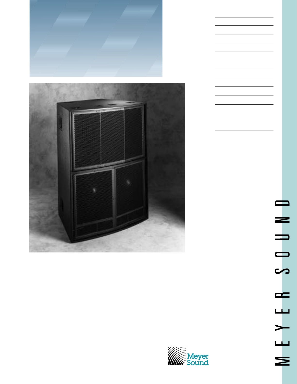
The Meyer Sound MSL-5 is an extremely
high-power, high-definition loudspeaker
system designed for large-scale music
reinforcement and public address applications. Unique in its class, it combines
exceptionally consistent directivity with
seamless arraying performance for precise
coverage control.
The MSL-5 comprises an all-horn,
integral loudspeaker cabinet constructed as
a 30-degree arrayable section, with two
proprietary 12-inch cone low-frequency
drivers in a vented, horn-loaded enclosure
and three 2-inch throat (4-inch diaphragm)
high-frequency horn drivers. The cabinet is
fitted with handles and with rigging lift
rings having a 1500 lb. maximum safe
working load capacity that are bolted
directly to an internal steel frame.
Designed specifically for use with SIM
System II, the MSL-5 requires the M-5
Control Electronics Unit, and its standard
minimum configuration comprises two
loudspeaker cabinets. The MSL-5 effectively
covers the vocal range, and may be used
alone for paging applications. In music
reinforcement applications, the DS-2 MidBass Loudspeaker is recommended to
supplement the low-frequency performance
of the system.
®
Sound Laboratories, Inc.
2832 San Pablo Avenue
Berkeley, CA 94702
(510) 486-1166
FAX (510) 486-8356
Page 2

Specifications
Acoustical — MSL-5/M-5 System
Frequency Response
2
1
Maximum SPL at 100 feet (30 meters)
Continuous
Peak
Coverage
MSL-5 Loudspeaker (one 30° section)
Driver Complement
HF DC Protection
Enclosure
Finish
Protective Grill
Rigging
Dimensions
Weight
Connector
M-5 Control Electronics Unit
Input Type
Output Type
Maximum Input/Output Level
Unbalanced
Balanced
Hum and Noise
Dynamic Range
Electronic Crossover Frequency
Driver Protection Circuits
Low Frequency
High Frequency
Indicators
Controls
Connectors
Input
Hi and Lo Output
Sense
100 Hz - 16 kHz ±4 dB
110 dB
120 dB
40° vertical x 60° horizontal
(2) MS-12 12" cone drivers
(3) MS-2001A 2" throat (4" diaphragm) horn
drivers
50 µf polypropylene capacitor
Vented, horn-loaded, 12-ply hardwood
Black textured, charcoal grey carpet or weather
protected (optional)
Two-piece hex punched metal screen, damped,
charcoal grey foam covering
Twelve points, pivoting lift rings, 1500 lb. maximum safe working load capacity
42 1/2" W x 56 3/4" H x 32" D
500 lbs (227 kg)
EP-4, EP-5 (Europe only), Pyle National (optional)
Active balanced, 10k ohms, ISO™ Input
Active push-pull, 600 ohm drive
+20 dBv
+26 dBv
-90 dBv (“A” weighted)
110 dB
800 Hz
RMS, peak and excursion limiters
RMS, peak and excursion limiters
Power LED
HF and LF Sense LED’s
HF and LF Limit LED’s
Safe LED
Power switch
Safe/AutoSafe switch
Input Attenuation (calibrated in dB)
3-pin XLR-type female, rear panel mounted
3-pin XLR-type male, rear panel mounted
Dual banana receptacles, rear panel mounted
Notes:
1. Acoustical specifications
are given for the standard
configuration of two 30°
sections.
2. Measured 5 meters on axis,
free-field conditions, pink
noise input, in third-octave
bands.
Page 3

M-5 Control Electronics Unit
UltraSeries™ M-5
Power
Sense
Hi
Lo
Limit
Autosafe
∞
20
10
8
4
3
2
1
0
Attn dB
5
6
Safe
Safe
Power Amplifier Requirements
Voltage Gain 16 dB, internally fixed
Power Output
0.5 sec. Burst at 4 Ohms 1800 watts
FTC Rating at 8 Ohms 1100 watts
Nominal (255 VAC) Operation With 4 ohm resistive load, reproduce three
specified burst waveforms
1, 2, 3
each continuously
for 1 hour without shutdown or limiting.
High (255 VAC) Mains Operation With 8 ohm resistive load, pass the FTC continu-
ous power test.
Low (200 VAC) Mains Operation With 4 ohm resistive load, reproduce a 400 msec
sine wave burst at 255 watts, 2.8 sec burst
interval, continuously for 1␣hour without shutdown
or limiting.
General Latch-up protection
Indicators for clipping, limiting, thermal overload
The MSL-5 requires a Meyer-approved
Type 3 power amplifier (for classification
details, contact Meyer Sound) conforming
to the following specifications:
Notes:
1) Cycle consisting of 50
msec sine wave at 120V
peak and 450 msec sine
wave at 24 V peak.
2) Cycle consisting of 25
msec sine wave at 120 V
peak and 975 msec sine
wave at 41 V peak.
3) Cycle consisting of 400
msec sine wave at 120 V
peak and 2400 msec
interval at 0 V.
Sine wave frequency in all
cases is 1 kHz.
The MSL-5 loudspeaker operates as a
system with the M-5 Control Electronics
Unit (one per channel). Optimized for the
MSL-5 and aligned at the factory, the M-5
contains frequency and phase response
alignment circuitry, and Meyer Sound’s exclusive SpeakerSense™ driver protection
circuitry, incorporating peak and RMS signal limiting as well as excursion protection.
A single-channel device operating at line
level, the M-5 is intended to be the final
component in the signal chain before the
power amplifier.
The M-5 SpeakerSense circuitry protects
the MSL-5 loudspeaker components from
damage due to overheating or excessive
excursion. This unique circuit continuously
monitors the power applied to the MSL-5
drivers, and limits the signal output when
the safe operating areas of the drivers are
exceeded. Until overload, the SpeakerSense
circuitry has no effect on the signal.
The M-5 SpeakerSense circuit incorporates Meyer Sound’s MultiSense™ func-
tion, which allows the unit to accommodate two amplifiers through separate Sense
inputs. The circuit, which implements an
analog OR condition, tracks the power
amplifier with the greatest output voltage
swing to control the system protection
limiters. This function prevents loss of
protection should one of the two power
amplifiers fail during high-level operation.
Also provided is a Safe/Autosafe switch
that affects the action of the protection limiting circuitry. When the switch is in the
Safe position, the RMS limiters come on at
6 dB lower power levels, affording added
protection when heavy continuous power
demands are placed on the system. A green
LED indicator is provided on the M-5 front
panel which lights when the M-5 is in the
Safe mode. In the Autosafe position, the
M-5 monitors system power over time, and
automatically switches into Safe mode if
the power demands become too high.
Page 4

42.52
56.75
32.28
22.51
14.00
7.38
32.19
C
SYM
24.18
1.63
3.12
C
30.42
15°
26.88
29.39
REF
Front Side Rear
Top
(TYP, BOTH ENDS)
EP-4 CONN, TYP
EP-5, EUROPE ONLY
PYLE, OPTIONAL
±0.50
28.63 C.G.
14.00 C.G. ±0.50
Physical Construction
Dimensions
Upper & Lower
Braces
3
⁄16" Steel,
ASTM A36
3
⁄8"-16 Reinforcement
Rods, B7 Alloy Steel
Fluid-Cooled High
Frequency Driver,
4-inch Diaphragm
(2-inch Throat)
Fluid-Cooled Back-
Vented 12-inch Cone
Low-Frequency Driver
3
⁄4" Plywood
Top & Bottom
3
⁄16" inch ASTM A36
Steel Support Channel
11 Ga. Steel
Side Braces
Resonance-
Damping Foam
Bracing Fastened With
3
⁄8"-16 Grade B Steel
Flathead Socket Screws
(32 Total)
Pivoting Lift Ring
1,500 lb. Load Capacity,
6:1 Safety Factor
(12 places)
High-Frequency
Horn Section
Flare-Adjusting
Foam Bullet
Low-Frequency
Vent
Low-Frequency
Horn Section
5
⁄8" Plywood Sides
Meyer Sound Laboratories has
devoted itself to designing,
manufacturing, and refining components that deliver superb sonic
reproduction. Every part of every
component is designed and built
to exacting specifications and
undergoes rigorous, comprehensive testing in the laboratories.
Research remains an integral,
driving force behind all production. Meyer strives for sound
quality that is predictable and
neutral over an extended lifetime
and across an extended range.
© 1994 Meyer Sound 04.022.016.01 C
Sound
engineering
for the art
and science
of sound.
Meyer Sound Laboratories, Inc.
2832 San Pablo Avenue
Berkeley, CA 94702
(
510
) 486-1166
FAX (
510
) 486-8356
 Loading...