


M3D-SUB
QUICKFLY RIGGING MANUAL
M3D™ and M3D-Sub
M SERIES
v
DECLARATION OF CONFORMITY ACCORDING TO ISO/IEC GUIDE 22 AND EN 45014
The manufacturer:
Meyer Sound Laboratories Inc.
2832 San Pablo Avenue
Berkeley, California 94702-2204, USA
Declares that the products: M3D™ and M3D-Sub conform to the
following product specications:
Safety: EN60065: 1998
IEC60065: 1998
EMC: EN55103-1: 1997 emission(1)
EN55103-2: 1997 immunity(2)
This device complies with the requirements of the Low Voltage
Directive 73 / 23 / EEC and the EMC Directive 89 /336 / EEC.
This device also complies with EN 55103-1 & -2. Operation is subject
to the following two conditions:
(1) this device may not cause harmful interference, and
(2) this device must accept any interference received, including
interference that may cause undesired operation.
Environmental specications for Meyer Sound electronics products:
Operating Temperature: 0˚C to + 45˚C
Nonoperating Temperature: <-40˚C or > +75˚C
Humidity: to 95% at 35˚C
Operating Altitude: to 4600 m (15,000 ft)
Nonoperating Altitude: to 6300 m (25,000 ft)
Shock: 30g 11 msec half-sine on
each of 6 sides
Vibration: 10 Hz to 55 Hz (0.010 m
peak-to-peak excursion)
Ofce of Quality Manager
Berkeley, California USA
July 19, 2002
© 2003 Meyer Sound. All rights reserved.
M3D and M3D-Sub QuickFly® Rigging Manual
The contents of this manual are furnished for informational purposes only, are subject to change without notice, and should not be construed as a
commitment by Meyer Sound Laboratories Inc. Meyer Sound assumes no responsibility or liability for any errors or inaccuracies that may appear
in this manual.
Except as permitted by applicable copyright law, no part of this publication may be reproduced, stored in a retrieval system, or transmitted, in any
form or by any means, electronic, mechanical, recording or otherwise, without prior written permission from Meyer Sound.
M3D, TruPower, RMS, BroadbandQ, MAPP Online and REM are trademarks of Meyer Sound. Meyer Sound, SIM and QuickFly are registered
trademarks of Meyer Sound (Reg. U.S. Pat. & Tm. Off.). All third-party trademarks mentioned herein are the property of their respective trademark
holders.
Printed in the U.S.A.
Part Number: 05.105.400.01, Rev. B
iv
SYMBOLS USED
!
!
These symbols indicate important safety or operating features in this booklet and on the chassis.
Dangerous voltages: risk of
electric shock
Pour indiquer les risques
résultant de tensions
dangereuses
Zu die gefahren von
gefährliche spanning zeigen
Para indicar voltajes
peligrosos.
Important operating
instructions
Pour indequer important
instructions
Zu wichtige betriebs-
anweisung und unter-
haltsanweisung zeigen
Instrucciones importantes
de funcionamiento y/o
manteniento
IMPORTANT SAFETY INSTRUCTIONS
1. Read these instructions.
2. Keep these instructions.
3. Heed all warnings.
4. Follow all instructions.
5. Do not use this loudspeaker near water.
6. Clean only with dry cloth.
7. Do not block any ventilation openings. Install
in accordance with Meyer Sound's installation
instructions.
8. Do not install near any heat sources such as radiators,
heat registers, stoves, or other apparatus that produce
heat.
9. Do not defeat the safety purpose of the groundingtype plug. A grounding-type plug has two blades and
a third grounding prong. The third prong is provided
for your safety. If the provided plug does not t into
your outlet, consult an electrician for replacement of
the obsolete outlet.
10. Protect the power cord from being walked on
or pinched particularly at plugs, convenience
receptacles, and the point where they exit from the
loudspeaker. The AC mains plug or appliance coupler
shall remain readily accessible for operation.
Frame or chassis Protective earth ground
Masse, châssis Terre de protection
Rahmen oder chassis Die schutzerde
Armadura o chassis Tierra proteccionista
11. Only use attachments/accessories specied by Meyer
Sound.
12. Use only with the caster rails or rigging specied by
Meyer Sound, or sold with the loudspeaker. Handles
are for carrying only.
CAUTION: Rigging should only be done by
experienced professionals.
13. Unplug this loudspeaker during lightning storms or
when unused for long periods of time.
14. Refer all servicing to qualied service personnel.
Servicing is required when the loudspeaker has been
damaged in any way, such as the power-supply cord
or plug is damaged, liquid has been spilled or objects
have fallen into the loudspeaker, the loudspeaker has
been exposed to rain or moisture, does not operate
normally, or has been dropped.
15. This loudspeaker provides protection against direct
sprays of water up to 15° from vertical. Rating IP42 in
accordance with IEC 60529.
v

vii
SAFETY STATEMENT
PLEASE READ THIS SECTION CAREFULLY AND IN
ITS ENTIRETY. IT CONTAINS CRITICAL INFORMATION
REGARDING SAFETY ISSUES, INCLUDING GUIDELINES
FOR GENERAL SAFE USE OF RIGGING SYSTEMS AS
WELL AS ADVISORIES ON GOVERNMENT REGULATIONS
AND LIABILITY LAWS. MEYER SOUND CANNOT BE
HELD RESPONSIBLE FOR CONSEQUENCES THAT MAY
ENSUE DUE TO FAILURE TO READ AND COMPLY WITH
INFORMATION IN THIS SECTION.
SCOPE OF THIS MANUAL
Although this manual contains much useful information on
rigging in general, it does not claim to be a comprehensive
resource on the subject. This manual assumes that
the owners and/or users of a QuickFly system are
knowledgeable and experienced in the areas of rigging
and ying loudspeaker systems. MANY ISSUES OF
CRUCIAL CONCERN, SUCH AS THE DETERMINATION
OF APPROPRIATENESS AND CONDITION OF VENUE
RIGGING POINTS, CANNOT BE ADDRESSED HERE.
THEREFORE, THE USER MUST ASSUME ALL
RESPONSIBILITY FOR THE APPROPRIATE USE OF
QUICKFLY SYSTEMS IN ANY PARTICULAR LOCATION
OR CIRCUMSTANCE.
THE SUSPENSION OF LARGE, HEAVY OBJECTS IN
PUBLIC PLACES IS SUBJECT TO NUMEROUS LAWS
AND REGULATIONS AT THE NATIONAL/FEDERAL,
STATE/PROVINCIAL, AND LOCAL LEVELS. THIS
MANUAL DOES NOT ADDRESS THE SPECIFICS OF
ANY SUCH APPLICABLE LAWS AND GOVERNMENT
REGULATIONS. THIS MANUAL DETAILS PROCEDURES
AND PRACTICES CONSISTENT WITH THOSE
GENERALLY ACKNOWLEDGED AS ALLOWABLE AND
SAFE IN THE UNITED STATES. HOWEVER, THE USER
MUST ASSUME RESPONSIBILITY FOR MAKING SURE
THAT USE OF ANY QUICKFLY SYSTEM AND ITS
COMPONENTS IN ANY PARTICULAR CIRCUMSTANCE
OR VENUE CONFORMS TO ALL APPLICABLE LAWS
AND REGULATIONS IN FORCE AT THE TIME.
All load ratings and other specications given in this
manual are the result of accepted engineering practice
and careful testing. However, such specications and
ratings are subject to change. USERS ARE ADVISED
TO CHECK THE QUICKFLY SECTION OF THE MEYER
SOUND WEBSITE AT
http://www.meyersound.com
OR CONTACT TECHNICAL SUPPORT AT REGULAR
INTERVALS TO CHECK FOR UPDATED OR REVISED
INFORMATION.
REGULATORY COMPLIANCE
The engineering practices and safe working load (SWL)
ratings of the QuickFly system are in full compliance with
all known regulatory statutes currently applicable in the
United States. Unless otherwise specied, all working
loads are based on a 7:1 safety factor. However, as
noted above, there are wide variations internationally in
the regulations and practices applying to suspension of
sound systems in public places. Although regulations in
the United States are generally among the most stringent,
safety codes may be even stricter in a few localities
(such as those highly prone to earthquakes). In addition,
applicable safety codes are open to interpretation:
Government ofcials in one location may have a stricter
interpretation than another local ofcial, even when
operating under the same regulations and in the same
legal jurisdiction.
CONSEQUENTLY, USERS OF QUICKFLY RIGGING
SYSTEMS SHOULD BE PREPARED TO TAKE
ADDITIONAL SAFETY ASSURANCE MEASURES BEYOND
THOSE OUTLINED IN THIS MANUAL. IN ALL CASES,
IT IS THE RESPONSIBILITY OF THE USER TO MAKE
CERTAIN THAT ANY MEYER SOUND LOUDSPEAKER
SYSTEM IS SUSPENDED IN ACCORDANCE WITH ALL
APPLICABLE NATIONAL/FEDERAL, STATE/PROVINCIAL,
AND LOCAL REGULATIONS.
LOAD RATINGS AND SPECIFICATIONS
Long-term safe operation is a central concern in the
design and manufacture of any rigging/ying system.
Meyer Sound has taken great care in material selection
and component design. In all critical cases, load points
are redundant, with a safety margin that allows one or
more load points to fail while maintaining system integrity.
After manufacture, all load-critical system components are
individually inspected.
vi

Advisory Note: Safety Responsibilities “Above
the Hook”
In most touring applications of rigging systems, the
touring sound provider is normally responsible for
ensuring the safety of the suspension system only below
the attachment point. The safety and suitability of the
attachment point is generally seen as the responsibility
of the venue owner or operator. However, this distinction
(“above the hook” versus “below the hook”) can be open
to interpretation. Touring system operators are advised
to double-check to make certain that attachment points
are approved and suitably load rated, and that the points
used are those identied as such by the venue owner
or operator. AS AN EXTRA PRECAUTION, CAREFUL
INSPECTION OF THE ATTACHMENT POINTS IS ADVISED
BEFORE FLYING, PARTICULARLY IN OLDER VENUES OR
THOSE HOSTING FREQUENT EVENTS USING LARGE
SOUND AND LIGHTING SYSTEMS. In any case, Meyer
Sound QuickFly systems are intended only for suspension
from approved rigging points, each known to have ample
SWL margins for the system components suspended
below them.
INSPECTION AND MAINTENANCE
The Meyer Sound QuickFly systems are an assembly of
mechanical devices, and are therefore subject to wear and
tear over prolonged use, as well as damage from corrosive
agents, extreme impact, or inappropriate use.
In addition to routine checks on the road for touring
systems, Meyer Sound also recommends a careful,
comprehensive system examination and testing “at
home” in the warehouse or other appropriate location at
regular intervals. At this time, each component should be
carefully inspected under ideal lighting conditions, and
then the entire system should be own as used for a nal
comprehensive check.
If any anomalies or defects are discovered that could
possibly affect the safety or integrity of the system, any
affected parts or subsystems should be replaced in their
entirety before that part of the system is own again.
REPLACEMENT PARTS
Any component found to be defective, or any safetyrelated component you even suspect might be defective,
should be replaced with the equivalent, approved part.
Parts specic to a QuickFly system should be ordered
directly from Meyer Sound. No attempt should be made
to substitute what appears to be equivalent or “mostly the
same” generic replacements. Some parts used in QuickFly
systems are identical to those used in other rigging
applications. To the best of our knowledge, most of these
suppliers are reputable and their products are reliable.
However, Meyer Sound has no way of assuring the quality
of products made by these various suppliers. Therefore,
Meyer Sound is not responsible for problems caused by
components that were not supplied by Meyer Sound.
BECAUSE OF THE SAFETY ISSUES INVOLVED, USERS
MUST ADOPT AND ADHERE TO A SCHEDULE OF
REGULAR INSPECTION AND MAINTENANCE. IN
TOURING APPLICATIONS, KEY COMPONENTS MUST
BE INSPECTED BEFORE EACH USE. Such inspection
includes examination of all load-bearing components
for any sign of undue wear, twisting, buckling, cracking,
rusting, or other corrosion. In regard to rust and corrosion,
the main components of a QuickFly system are either
protected by an exterior coating or made from stainless
steel, which is impervious to rust and resistant to most
corrosive uids. Nevertheless, normal use and shipping
vibrations can wear through the protective coatings,
and extremely corrosive uids (such as battery acid)
can cause severe damage with prolonged exposure
even to protected parts. Particular attention should be
given to screws, bolts, and other fasteners to make
certain the ttings are tight and secure. Metal seams and
welds should be examined for any sign of separation or
deformation. Meyer Sound strongly recommends that
written documentation be maintained on each QuickFly
system, noting date of inspection, name of inspector,
points of system checked, and any anomalies discovered.
TRAINING
Considering their sophistication and exibility, QuickFly
systems are relatively straightforward and easy to use.
Nevertheless, key points of assembly, rigging, and ying
that must be fully mastered before a system is own.
Users should read this manual in its entirety before
attempting to deploy any QuickFly system. You may make
additional copies of this manual as necessary for in-house
use; copies may not be made for any other purpose.
vii

viii
ix

CONTENTS
Introduction 1
Assembling Blocks for Transport 1
Truck Pack 1
M3D Transport 3
Before Hanging an M3D Array 3
Choosing Rigging Point Capacities 3
M3D Placement Calculator 4
Measuring a Venue 5
General Hanging Considerations 6
Do’s and Don’ts 6
Lifting Mechanisms 7
Use Front and Back Motors Whenever Possible 7
Choosing Pickup Points 8
Array Assembly and Angle Adjustment 9
Starting Array Assembly 9
Stacking an M3D Array 10
Attaching Motors to the MTG-3D Top Grid 10
Attaching M3Ds to the MTG-3D Top Grid 11
Adjusting Angles 12
MTG-3D Top Grid to First M3D Angle Adjustment 12
Adjusting Top M3D Top Grid Downtilt 12
Adjusting MTG-3D Top Grid Uptilt 13
Adjusting Splay Angle in an Array 14
Removing Caster Rails 15
Adding a Block of M3Ds to an Array 16
Flying a Completed Array 18
Including M3D-Subs in an Array 19
Striking the Array 19
Appendix A — Congurations and Load Ratings 20
General 20
About These Load Ratings 20
Measured Angles 20
Angle Between Bridle and Grid 20
Maximum Top Grid Angle 20
Bridle Leg Lengths 20
Conguration A 21
Conguration B 23
Conguration C 25
Conguration D 27
Conguration E 29
Conguration F 30
Conguration G 31
ix

1
Appendix B — Physical Specications 32
M3D Physical Specications 32
M3D-Sub Physical Specications 33
MTG-3D Top Grid Physical Specications 33
Appendix C — MTF-3D Transition Frame Assembly Procedure 35
MTF-3D Transition Frame 35
Attaching Loudspeakers to Transition Frame 35
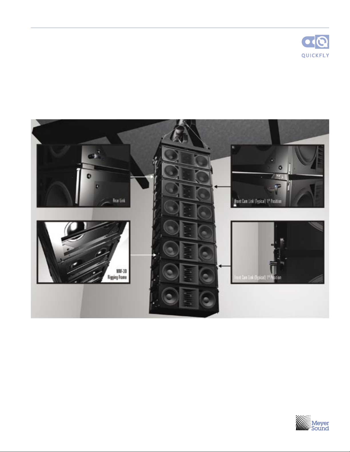
Attaching the Adjustable Link Assembly to the MRF-3D Rigging Frames 36
Rear 36
Front 37
Glossary 38
x
!
!
M3D AND M3D-SUB QUICKFLY RIGGING MANUAL
INTRODUCTION
The M3D and M3D-Sub QuickFly rigging system is a
complete integrated solution for transporting and ying
M3D and M3D-Sub loudspeakers. This system includes
everything below the motors, to the caster rails and covers
that carry and protect the system in transport. All the
hardware for rigging the system remains captive to the
loudspeakers and MTG-3D Top Grid. This manual is a
guide to transporting, assembling, adjusting, and striking
a vertical array of M3D and M3D-Subs. Also included
is information on the Meyer Sound M3D Placement
Calculator, a tool that provides the necessary mechanical
setup information for prerigging and hanging an M3D and
M3D-Sub system. For information on the operation of the
M3D and M3D-Sub, please refer to the M3D Operating
Instructions, part number 05.105.022.01.
Throughout this document, we refer to the M3D
loudspeaker. To save space and avoid unnecessary
repetition, please note that in all cases — unless otherwise
indicated — “M3D” includes M3D and M3D-Sub. For
example, when we state “The rst step in preparing M3Ds
for transportation…” What is implied is, “The rst step in
preparing M3Ds and M3D-Subs for transportation…”
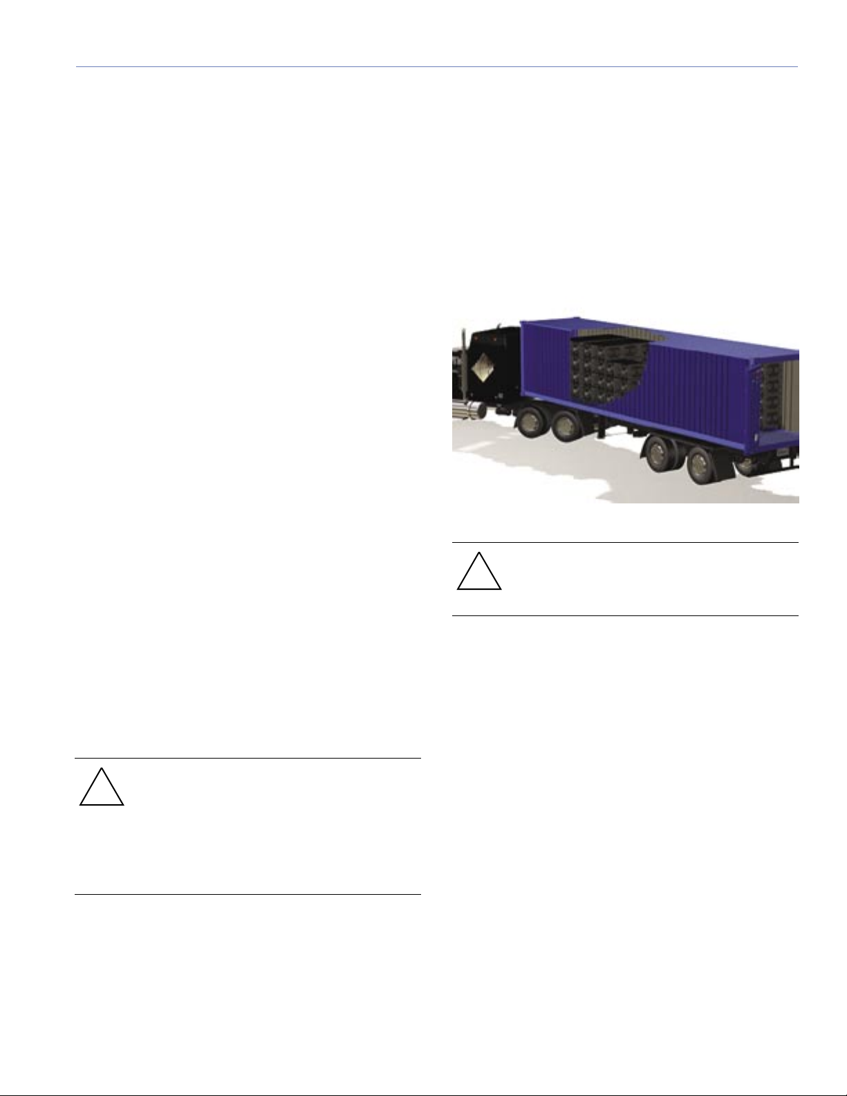
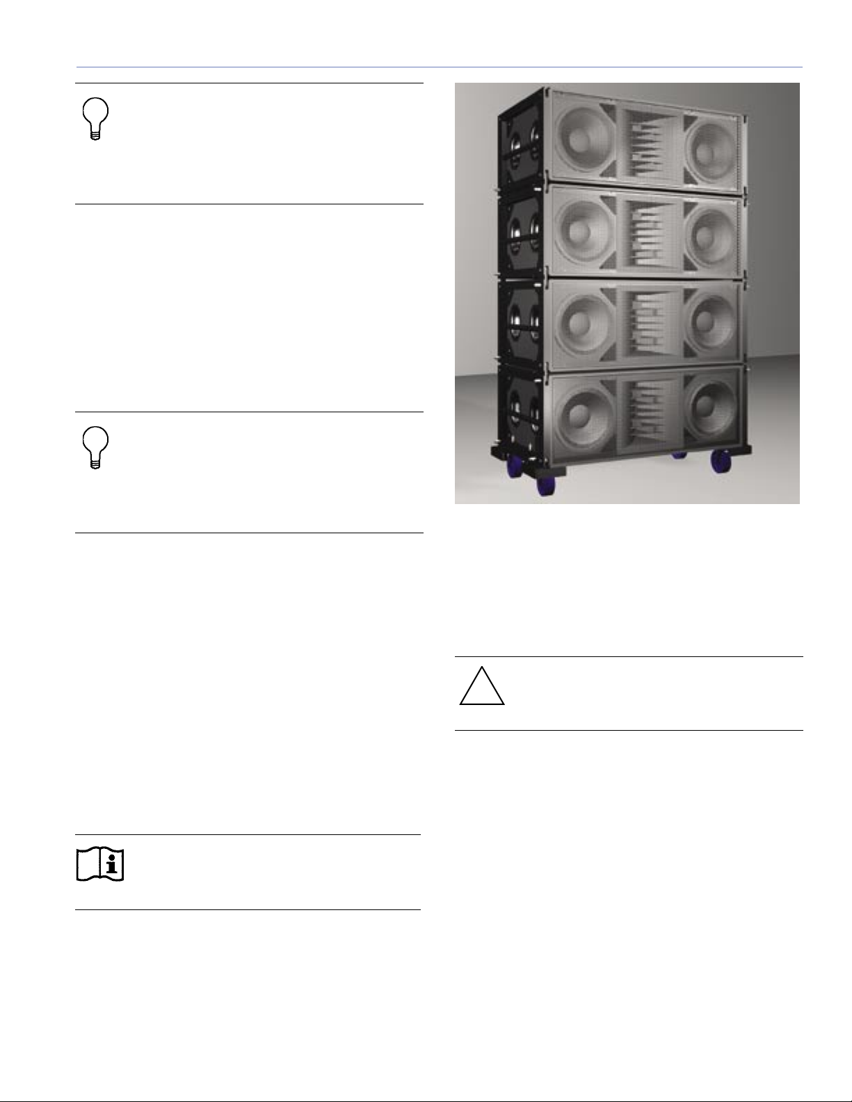
Truck Pack
M3Ds can be transported in blocks from one to four M3Ds
high, whichever conguration maximizes loading in the
truck and meets your needs (see Figure 1). These M3D
blocks can be packed three wide in a trailer. Blocks of one
or two M3Ds are lighter to move when on site, but may not
make as efcient use of truck cargo space.
Figure 1. M3Ds packed in truck for transport
ASSEMBLING BLOCKS FOR TRANSPORT
The rst step in preparing M3Ds for transportation is
to assemble the loudspeakers in modular blocks for
easy assembly. The number of M3Ds in a block will be
determined by the safest and most practical size for your
truck pack and load-in considerations.
The procedure in the section “Array Assembly and Angle
Adjustment,” may be considered suitable for assembling
the blocks for transport.
CAUTION: Take care if you use a forklift for
making or moving M3D blocks. There is no
protective metal frame at the bottom of an
M3D while it is on its caster rails, and the
forklift may damage the wooden cabinet.
Using protective padding or material over the
forks is recommended.
CAUTION: Because of weight and stability
considerations, we recommend that transport
blocks not exceed four M3Ds high.
1
3
Using a three- or four-high M3D block will make each
block heavier (see Table 1) and less stable, so the blocks
will require extra care when rolling over an uneven surface
and up truck ramps. Conversely, larger blocks will make
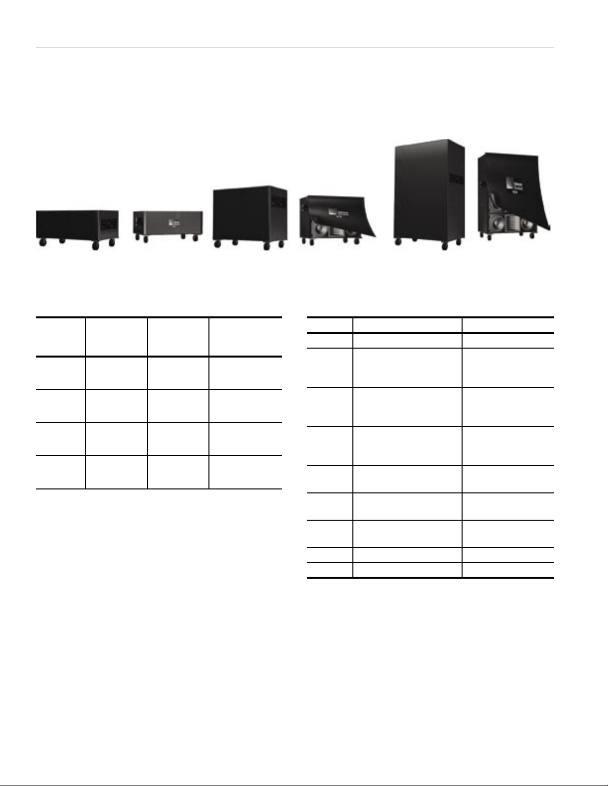
The optional M3D transit covers, shown in Figure 2, are
constructed of wear-resistant nylon fabric with Velcro
closures to protect the M3D and loudspeakers from scuffs
and weather during transport.
more efcient use of a truck’s cargo space and make a
more efcient load-in and strike.
Figure 2. M3D transit covers shown covering one-, two-, and four-high M3D blocks
Table 1: M3D Transport Blocks
Number
of M3Ds
M3D Block
Weight
Block Height
Mounted on
Transit Cover
Part Number
Caster Rail
1 415 lbs
188.24 kg
2 830 lbs
376.48 kg
3 1245 lbs
564.72 kg
4 1660 lbs
752.96 kg
28.56"
7254 mm
49.31"
12525 mm
70.06"
17795 mm
90.81"
23066 mm
66.105.036.01
66.105.037.01
66.105.040.01
66.105.038.01
Table 1 notes:
1. The table above refers to M3Ds only. If transport
blocks include M3Ds and M3D-Subs or M3D-Subs
only, recalculate the block weights by replacing the
gure of 415 lbs (188.24 kg) with 395 lbs (179.17 kg).
2. An attached MTG-3D Top Grid will add approximately
11.0 inches (279.4 mm) to the height of the block and
approximately 308 lbs (139.71 kg) to the total weight
of the block.
Table 2. M3D Rigging and Replacement Parts
Item Description Part Number
MTG-3D Top grid for M3D arrays 45.105.028.01
MTF-3D Transition frame from
40.105.092.01
M3D arrays to CQ-2
and MSL-4 downlls
MRF-3D M3D & M3D-Sub Left
40.105.103.01
Side Rigging Frame
Replacement Kit
MRF-3D M3D & M3D-Sub Right
40.105.103.02
Side Rigging Frame
Replacement Kit
M3D & M3D-Sub Front
40.105.104.01
Cam-Link Replacement
M3D & M3D-Sub Rear
40.105.104.02
Link Replacement
M3D Rigging Spacer
68.105.072.01
Tool
Caster Rail Kit 40.105.033.01
QRP M3D Quick Release Pin 134.007
3. The measurements are at 0˚ splay angles.
4. These measurements include the cover thickness.
5. The block height measurements include 7.81 inches
(198.4 mm) added to the block height by the caster
rails.
2
TIP: Meyer Sound’s optional transit covers
!
will protect M3Ds stacked for transport. They
are easy to use, because one side opens
with Velcro seams, allowing two stagehands
to easily put on the cover without having to
lift it over the top of the block.
We suggest you strap each block, once loaded, with a
cargo strap to prevent rubbing through the covers and
damaging the M3D cabinets or adjacent equipment.
M3D Transport
As a reference, a three-high M3D block weighs
approximately 1245 pounds (564.72 kg), or about the
weight of a large-format mixing console, including its
case, a piano, or a set-cart.
TIP: Attaching the MTG-3D Top Grid to
the uppermost block of the array while
transporting an M3D system can minimize
labor and setup time. Use a wraparound,
open-top cover to protect the four sides of
the cabinets.
If you transport the block with the MTG-3D Top Grid
attached, it should be in the middle of the outer two
blocks to allow the MTG-3D Top Grid to slide over the
other two blocks. This will also keep the MTG-3D Top
Grid away from the wall of the truck. If the block with the
MTG-3D Top Grid is placed against the truck wall, it must
be loaded with the extension side of the MTG-3D Top Grid
facing the inside (as opposed to the wall) of the truck. If
it is oriented toward the wall, the extra space taken will
prevent the third block from tting beside the other two.
Figure 3. Block of four M3Ds on caster rails with transit cover
removed
BEFORE HANGING AN M3D ARRAY
Consider the following before you start hanging an M3D
array:
CAUTION: We strongly recommend that you
use a professional rigger when hanging any
system.
Alternatively, the cabinets may be transported in a twohigh module. A stacking row of other equipment may be
lifted on top while in the truck. The approximately 830pound (376.48 kg) weight for the two-high module will be
easier to manage in some types of venues.
NOTE: Because fewer M3Ds travel in each
block, more stage space, rigging, and
assembly time will be necessary.
CHOOSING RIGGING POINT CAPACITIES
The MTG-3D Top Grid is designed to allow the suspension
of all approved vertical M3D array congurations. For a list
of approved array congurations and their specications,
refer to “Appendix A — Congurations and Load Ratings.”
The total allowable tilt of the MTG-3D Top Grid with an
array hung under it is ±25˚. The MTG-3D Top Grid allows
10˚ of vertical angle adjustment between the MTG-3D Top
Grid and the rst cabinet, from 0˚ to ±5˚ in one degree
increments. Refer to the section “MTG-3D Top Grid to
First M3D Angle Adjustment” for details.
3
5
When choosing your rigging point capacities, always
keep in mind that the entire weight of the array may shift
completely to either the front or back points. Three factors
contribute to variations in the center of gravity:
the venue, as shown in Figure 4, can display up to three
balconies. The Meyer Sound M3D Placement Calculator is
approved by a certied structural engineering rm.
1. The curvature of the array
2. The tilt of the entire array inclusive of the MTG-3D Top
Grid
3. The number and types of M3D elements and downlls
used
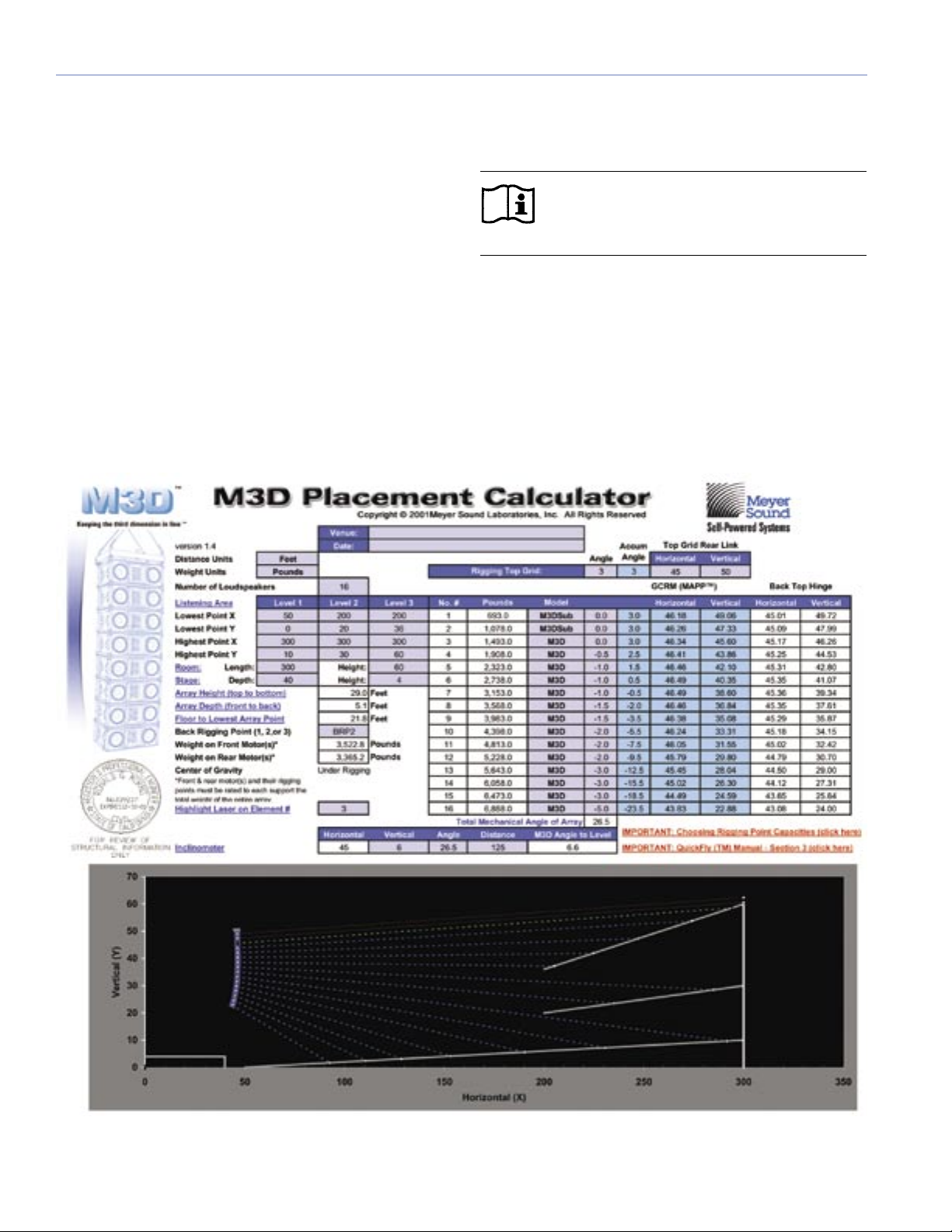
M3D PLACEMENT CALCULATOR
The M3D Placement Calculator, shown in Figure 4,
is a mechanical design tool for calculating structural
information about an M3D and/or M3D-Sub array. It is
implemented as an Excel spreadsheet and provides
information regarding rigging loads and array placement
and aiming. A customizable graphic representation of
NOTE: You need a computer loaded with
Microsoft Excel in order to run the M3D
Placement Calculator.
The calculator is available online by lling out an
application form on the Meyer Sound web site at:
http://www.meyersound.com/forms/m3dcalcform.htm
The download location and password will be emailed to
you at the email address you enter on your application.
Figure 4. M3D Placement Calculator and link to detailed user instructions
4

MEASURING A VENUE
You are required to enter the venue’s dimensions into the
M3D Placement Calculator.
If scaled sectional drawings of the venue are available, you
can use the dimensions from these drawings to determine
the M3D array setup.
If scaled sectional drawings of the venue are not available,
you can measure the venue by using a laser range nder,
or alternatively, a long measuring tape.
1
Another less accurate option is to measure the venue by
pacing it off, using a pedometer similar to item 3 in Figure
5, and using this measurement to make an educated
estimate.
Figure 5 shows some tools that can aid in the process of
aligning an array and focusing it to the requirements of a
specic venue:
1. Binoculars
2. Laser measuring tool
3. Pedometer
4. Laser inclinometer
5. Self-leveling, four-way laser
2
Figure 5. Useful array alignment tools
3
4
5
5
7
Once you enter measurements into the M3D Placement
Calculator, it will help you visualize the approximate
vertical splay angles needed. The calculator will also help
with other rigging considerations. Save the results of these
calculations for use when you assemble the M3D array
as described in the section “Array Assembly and Angle
Adjustment.”
A laser measuring tool, similar to item 2 in Figure 5, may
also be used to measure the height of venue rigging
beams and the trim height of the array.
TIP: When making measurements and
adjustments to an array, it is much more
convenient to use a laser measuring tool than
a measuring tape.
The M3D Placement Calculator is not an acoustical design
tool and cannot be used to predict array coverage. To
facilitate accurate coverage predictions, however, the
calculator provides detailed positional data that can be
entered into Meyer Sound’s MAPP Online™ acoustical
prediction program. In combination, these two Meyer
Sound tools give you the ability to predict sound coverage
and to calculate the physical placement of arrays to
accomplish the prediction.
GENERAL HANGING CONSIDERATIONS
Before starting the actual array assembly and hanging
process, review this section:
DO’S AND DON’TS
DO: Use only properly trained personnel to assemble and
hang M3D arrays.
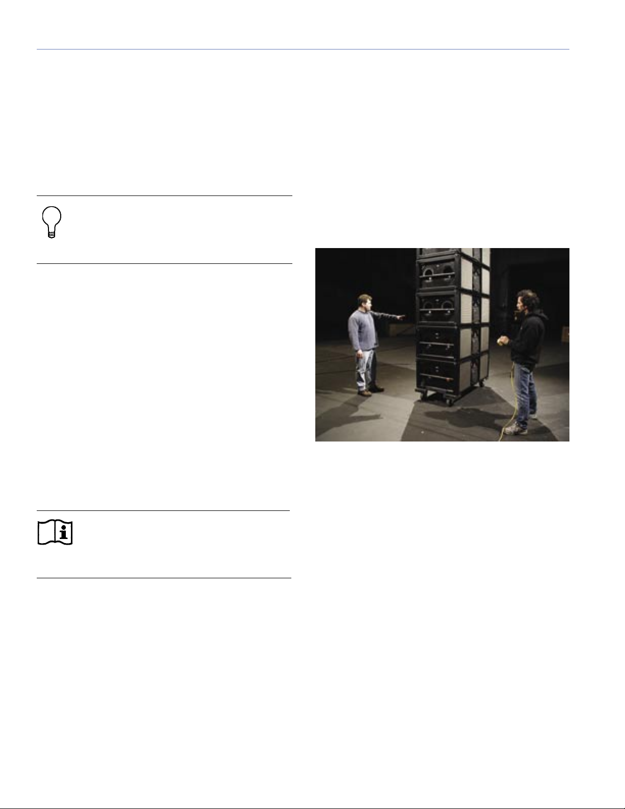
DO: Pay attention at all times when moving the array with
a motor system. It is often difcult to see the physical
orientation when you are very close to the array. Have a
spotter, as shown in Figure 6, provide “a second set of
eyes” at a position different from the motor operator.
The weight distribution elds shown in the M3D Placement
Calculator are calculated for the array in its nal trim
position. During array assembly, it may be necessary for
the front or rear motors to temporarily support the entire
weight of the array. Therefore, when planning the rigging
point loads, you must always plan on this fact regardless
of the results shown in the "Weight on Front/Rear Motor"
elds.
NOTE: The Instructions link at the top of the
M3D Placement Calculator page provides
complete instructions for using the M3D
Placement Calculator.
Figure 6: Using a spotter as a “second set of eyes”
DON’T: Place hands between the cabinets.
DON’T: Use the rear cabinet ring/stud ttings for rigging
cabinets or pull back. Use them for system cable support
only. (Refer to the M3D Operating Instructions for cabling
details.)
DON’T: Allow the center of gravity to move outside of the
MTG-3D Top Grid once it is in its nal trimmed position.
The M3D's rigging system is designed to be rigid, which
allows for tilting up or down while maintaining the set
relative splay between cabinets and alleviating the need
for any pull back to be used.
6
LIFTING MECHANISMS
The number and lift capacity of chain motors used to lift
the array are dependent on the array’s combined weight,
including the weight of any underhung clusters, and
its orientation and splay. For a smaller array, it may be
sufcient to use 1-ton motors, but for larger arrays, 2-ton
motors may be necessary.
The lift capacity of any single motor or set (in a fourhoist conguration) of motors must be sized to support
the entire weight of the array, including cable. When you
are assembling the array, as the cabinets are attached,
level the bottom cabinet to allow the next waiting block
to be attached. Because there is often a vertical curve in
the array, the upper cabinets have an increasing uptilt.
At some point, depending on the vertical splay angles
used, the rear motor(s) may not be supporting any weight.
At this point, the front motor(s) must support the entire
weight of the array while it is being assembled.
Conversely, once the array is assembled and own into its
nal position, it is likely that the MTG-3D Top Grid will be
much closer to level. In this conguration, the majority of
the weight then shifts to the rear motor(s). If the array has
downtilt and a curve is being used, the weight may then
shift closer to the rear motor(s).
Furthermore, when you are using three or four motors
and lifting the array during assembly, the array may not
be level in the other plane (onstage vs. offstage). Further
weight will shift onto the highest motor, requiring that
motor to have a larger capacity.
The MTG-3D Top Grid is designed to have the motors
attached to its pickup points at either the center set of the
MTG-3D Top Grid’s main frame, the four corner sets on
the main frame, or the front and rear sets of tabs on the
extension frame in its retracted or extended position.
USE FRONT AND BACK MOTORS WHENEVER
POSSIBLE
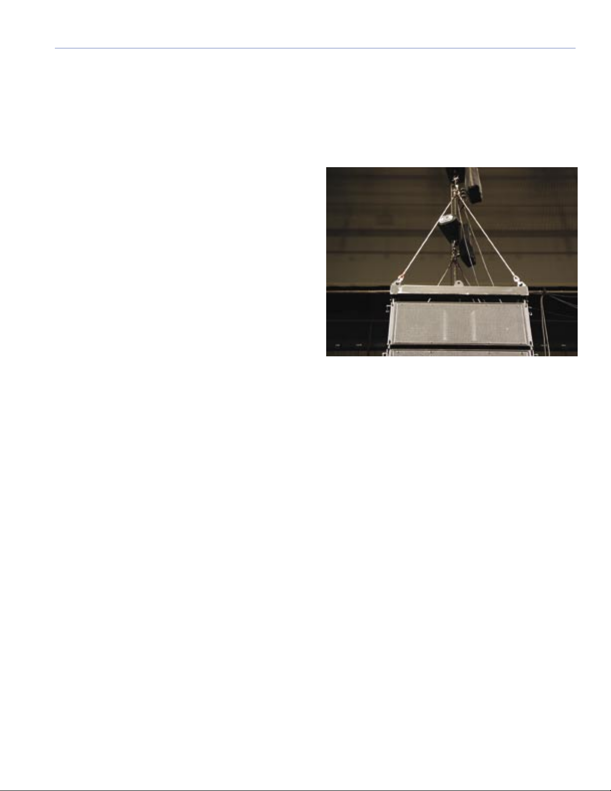
Front-to-back bridle point congurations, illustrated in
Figure 7 and congurations A, E, and F in “Appendix A
— Congurations and Load Ratings,” allow the use of
motors to provide the necessary vertical tilt to the array.
This provides the easiest conguration to use for trimming
vertical tilt for an array.
Figure 7. Bridles may be used in a front-to-back hanging
conguration
If front and back motors cannot be used to provide the
required vertical tilt of an array, such as congurations
B, C, and D in “Appendix A — Congurations and Load
Ratings,” the technician can use the variable tilt capability
of the MTG-3D Top Grid, to achieve the desired vertical tilt
angle for the array. Refer to the section “MTG-3D Top Grid
to First M3D Angle Adjustment.”
Refer to the rigging congurations and their associated
tables in “Appendix A — Congurations and Load
Ratings” for details on allowable weights, pickup points,
bridle lengths, and the maximum allowable number of
loudspeakers for the conguration you will be rigging.
7
 Loading...