

Meyer Sound MSL-4 User Manual
Operating Instructions
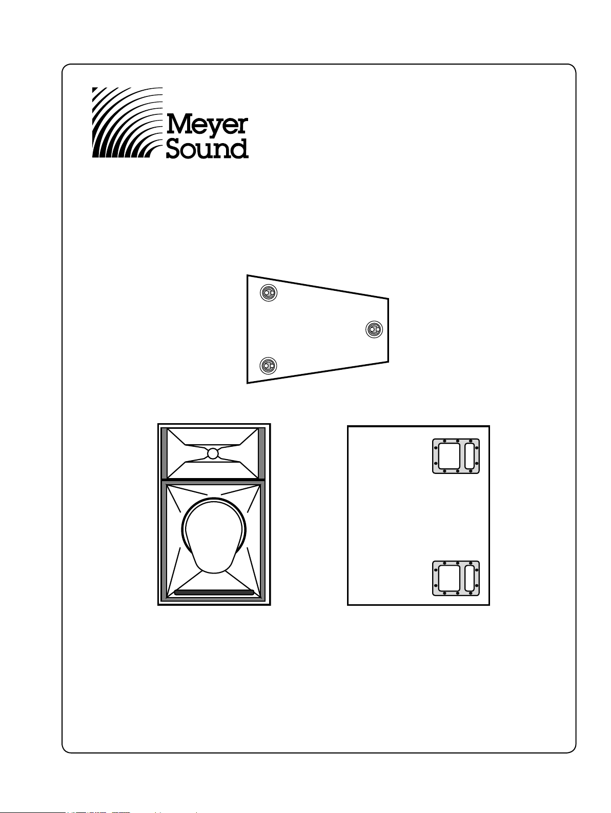
MSL-4
Self-Powered Loudspeaker System
Top
Front
Copyright © 1999
Meyer Sound Laboratories, Inc.
All rights reserved.
Part # 05.031.008.01 Rev C
Keep these important operating instructions.
Side

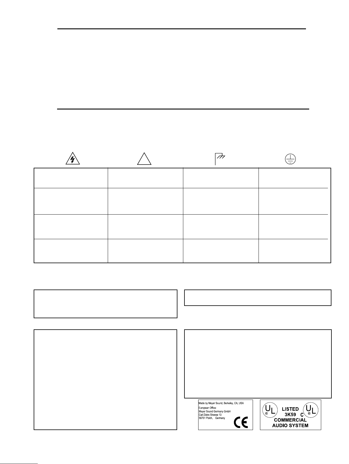
Safety Summary
!
English Français
• To reduce the risk of electric shock, disconnect the loudspeaker from the AC mains before installing audio cable.
Reconnect the power cord only after making all signal
connections.
• Connect the loudspeaker to a two-pole, three wire grounding mains receptacle. The receptacle must be connected
to a fuse or circuit breaker. Connection to any other type
of receptacle poses a shock hazard and may violate local
electrical codes.
• Do not install the loudspeaker in wet or humid locations
without using weather protection equipment from Meyer
Sound.
• Do not allow water or any foreign object to get inside the
loudspeaker. Do not put objects containing liquid on, or
near, the unit.
• To reduce the risk of overheating the loudspeaker, avoid
exposing it to direct sunlight. Do not install the unit
near heat-emitting appliances, such as a room heater or
stove.
• This loudspeaker contains potentially hazardous voltages.
Do not attempt to disassemble the unit. The unit contains
no user-serviceable parts. Repairs should be performed
• Pour réduire le risque d’électrocution, débranchez la
prise principale de l’haut-parleur, avant d’installer le
câble d’interface allant à l’audio. Ne rebranchez le bloc
d’alimentation qu’après avoir effectué toutes les connections.
• Branchez l’haut-parleur dans une prise de courant à 3
dérivations (deux pôles et la terre). Cette prise doit être
munie d’une protection adéquate (fusible ou coupe-circuit).
Le branchement dans tout autre genre de prise pourrait
entraîner un risque d’électrocution et peut constituer une
infraction à la réglementation locale concernant les installations électriques.
• Ne pas installer l’haut-parleur dans un endroit où il y a
de l’eau ou une humidité excessive.
• Ne pas laisser de l’eau ou tout objet pénétrer dans l’hautparleur. Ne pas placer de r´cipients contenant un liquide
sur cet appareil, ni à proximité de celui-ci.
• Pour éviter une surchauffe de l’haut-parleur, conservez-la
à l’abri du soleil. Ne pas installer à proximité d’appareils
dégageant de la chaleur tels que radiateurs ou appareils
de chauffage.
• Ce haut-parleur contient des circuits haute tension présentant un danger. Ne jamais essayer de le démonter. Il n’y a
aucun composant qui puisse être réparé par l’utilisateur.
Toutes les réparations doivent être effectuées par du personnel qualifié et agréé par le constructeur.
Deutsch Español
• Um die Gefahr eines elektrischen Schlages auf ein Minimum
zu reduzieren, den Lautsprecher vom Stromnetz trennen,
bevor ggf. ein Audio-Schnittstellensignalkabel angeschlossen wird. Das Netzkabel erst nach Herstellung aller Signalverbindungen wieder einstecken.
• Der Lautsprecher an eine geerdete zweipolige DreiphasenNetzsteckdose anschließen. Die Steckdose muß mit einem
geeigneten Abzweigschutz (Sicherung oder Leistungsschalter) verbunden sein. Der Anschluß der unterbrechungsfreien Stromversorgung an einen anderen Steckdosentyp
kann zu Stromschlägen führen und gegen die örtlichen
Vorschriften verstoßen.
• Der Lautsprecher nicht an einem Ort aufstellen, an dem
sie mit Wasser oder übermäßig hoher Luftfeuchtigkeit in
Berührung kommen könnte.
• Darauf achten, daß weder Wasser noch Fremdkörper in
das Innere den Lautsprecher eindringen. Keine Objekte,
die Flüssigkeit enthalten, auf oder neben die unterbrechungsfreie Stromversorgung stellen.
• Um ein Überhitzen dem Lautsprecher zu verhindern,
das Gerät vor direkter Sonneneinstrahlung fernhalten
und nicht in der Nähe von wärmeabstrahlenden Haushaltsgeräten (z.B. Heizgerät oder Herd) aufstellen.
• Im Inneren diesem Lautsprecher herrschen potentiell
gefährliche Spannungen. Nicht versuchen, das Gerät zu
öffnen. Es enthält keine vom Benutzer reparierbaren Teile.
Reparaturen dürfen nur von ausgebildetem Kundenienstpersonal durchgeführt werden.
• Para reducir el riesgo de descarga eléctrica, desconecte de la
red el altoparlante antes de instalar el cable de señalización
de interfaz de la segnale. Vuelva a conectar el conductor
flexible de alimentación solamente una vez efectuadas
todas las interconexiones de señalizatción.
• Conecte el altoparlante a un tomacorriente bipolar y trifilar
con neutro de puesta a tierra. El tomacorriente debe estar
conectado a la protección de derivación apropiada (ya sea
un fusible o un disyuntor). La conexión a cualquier otro
tipo de tomacorriente puede constituir peligro de descarga
eléctrica y violar los códigos eléctricos locales.
• No instale el altoparlante en lugares donde haya agua o
humedad excesiva.
• No deje que en el altoparlante entre agua ni ningún objeto extraño. No ponga objetos con líquidos encima de la
unidad ni cerca de ella.
• Para reducir el riesgo de sobrecalentamiento, no exponga
la unidad a los rayos directos del sol ni la instale cerca de
artefactos que emiten calor, como estufas o cocinas.
• Este altoparlante contiene niveles de voltaje peligrosos
en potencia. No intente desarmar la unidad, pues no
contiene piezas que puedan ser repardas por el usuario.
Las reparaciones deben efectuarse únicamente por parte
del personal de mantenimiento capacitado en la fábrica.
2
Contents
!
Safety Summary ...................................................................
2
Introduction ...................................................................4
AC Power .....................................................................4
Audio Input ..................................................................6
Amplification and Protection Circuitry .........................6
Symbols Used
These symbols indicate important safety or operating features in this booklet and on the chassis.
Dangerous voltages:
risk of electric shock
Pour indiquer les risques résultant de
tensions dangereuses
Zu die gefahren von gefährliche
spanning zeigen
Important operating
instructions
Pour indequer important instruc-
tions
Zu wichtige betriebsanweisung und unter-
haltsanweisung zeigen
Rigging ................................................................................. 8
Measurement and System Integration Tools ......... 8
Complete Systems ...................................................... 9
Driver Troubleshooting ........................................... 12
Array Design ............................................................. 13
Specifications ............................................................14
Controls and Connectors ........................................ 15
Frame or chassis
Masse, châssis
Rahmen oder chassis
Protective earth ground
Terre de protection
Die schutzerde
Para indicar azares provengo de
peligroso voltajes
Para indicar importante
funcionar y mantenimiento instruc-
ciones
Declaration of Conformity According to ISO/IEC Guide and EN 45014
The Manufacturer:
Meyer Sound Laboratories, Inc.
2832 San Pablo Avenue
Berkeley, California 94702-2204, USA
Conforms to the following Product Specifications:
Safety: EN 60065: 1994
EMC: EN 55022: 1987 - Class A
IEC 801-2: 1984 - 8 kV
IEC 801-3: 1984 - 3 V/m
IEC 801-4: 1984 - 0.5 kV Signal
The product herewith complies with the requirements
of the Low Voltage Directive 73 / 23 / EEC and
the EMC Directive 89 / 336 / EEC.
Office of Quality Manager
Berkeley, California USA
April 27, 1999
Armadura o chassis Tierra proteccionista
Declares that the product:
MSL-4
Product Optons: All
Operating temperature: 0oC to + 45oC
Nonoperating temperature: < -40o C or >
+75o C
Humidity: to 95% at 35o C
Operating Altitude: to 4600 m (15,000 ft)
Nonoperating altitude: to 6300 m (25,000 ft)
Shock: 30g 11 msec half-sine
on each of 6 sides
Vibration: 10 Hz to 55 Hz (0.010m
3

Introduction
The MSL-4 self-powered loudspeaker system is ideal for large
venues requiring long throw distances and precise coverage,
but can also be used effectively in smaller applications. Its high-
Q (narrow coverage) horn has a consistent beam width across
its entire frequency range, enabling efficient array design that
maximizes coverage and SPL for a given array size.
The MSL-4 contains independent amplifier and control
electronics for one 12” low frequency cone driver (in a hornloaded vented enclosure) and one high frequency horn driver
(2” throat, 4” diaphragm) in a compact trapezoidal cabinet. This
integrated design provides excellent performance, durability,
and reliability, eliminates amplifier racks, and simplifies
setup and installation.
The MSL-4 matches well with the Meyer Sound DS-4 self-powered mid/bass loudspeaker, the PSW-2 and 650-P self-powered
subwoofers, and also performs efficiently with the PSW-4. The
MSL-4 can be used as a full-range or mid-hi speaker and has
the following acoustical specifications:
Frequency Response ±4 dB 65 Hz – 18 kHz
Phase Response ±30° 450 Hz – 10 kHz
Coverage 40° H x 35° V
Dynamic Range > 110 dB
The MSL-4 can be equipped to operate with the Remote
Monitoring System™ (RMS) interface network and software
application. RMS displays signal and power levels, driver and
cooling fan status, limiter activity, and amplifier temperature
for all speakers in the network on a Windows-based PC. Contact
Meyer Sound for more information about RMS.
AC Power
When AC power is applied to the MSL-4, the Intelligent AC™
supply automatically selects the correct operating voltage, allowing the MSL-4 to be used in the US, Europe, or Japan
without manually setting a voltage switch. The Intelligent AC
power supply also protects the MSL-4 by performing surge
suppression for high voltage transients (up to 275V), minimizing inrush current, and filtering EMI. The MSL-4 uses a
NEMA L6-20P or IEC 309 male power inlet and satisfies UL,
CSA, and EC safety standards.
at 50 or 60Hz. Immediately after applying AC power, the green
Active LED on the user panel illuminates and the proper operating voltage is automatically selected, but the system is muted.
During the next three seconds, the primary fan turns on, the
main power supply slowly ramps on, and the system is enabled
to pass audio signals.
TROUBLESHOOTING NOTE: If the Active LED does not
illuminate or the system does not respond to audio input after
ten seconds, remove AC power to avoid possible damage to
the unit. Experienced electronics technicians with access to a
test bench can verify proper operation for the power supply and
amplifier system with The Meyer Sound Self-Powered Series MP-2
and MP-4 Field Verification Procedure (part # 17.022.066.01;
contact Meyer Sound to receive this document). All other users
should contact Meyer Sound or an authorized Meyer Sound
service center.
If the voltage decreases below the lower bound of either operating range (known as a brown-out period), the supply uses
current from its storage circuits and continues to function briefly.
The unit turns off if the voltage does not increase above the
threshold before the storage circuits are depleted. The length
of time that the MSL-4 continues to operate during brown-out
depends on how low the voltage drops and the audio source
level during this period.
If the voltage fluctuates within either operating range, automatic
tap selection stabilizes the internal operating voltage. This tap
selection is instantaneous and there are no audible artifacts. If
the voltage increases above the upper bound of either range,
the power supply turns off rapidly, preventing damage to the
unit.
If the MSL-4 shuts down due to either low or high voltage, the
power supply automatically turns on after three seconds if the
voltage has returned to either normal operating range. If the
MSL-4 does not turn back on after ten seconds, remove AC power
and refer to the TROUBLESHOOTING NOTE above.
Current Requirements
The MSL-4 presents a dynamic load to the AC mains which
causes the amount of current to fluctuate between quiet and
loud operating levels. Since different types of cables and circuit
breakers heat up (and trip) at varying rates, it is essential to understand the types of current ratings and how they correspond
to circuit breaker and cable specifications.
NOTE: Continuous voltages higher than 275V may damage
the unit!
Voltage Requirements
The MSL-4 operates safely and without audio discontinuity if
the AC voltage stays within the ranges 85–134V or 165–264V,
4
The maximum continuous RMS current is the maximum
RMS current over a duration of at least 10 seconds. It is used
to calculate the temperature increase in cables, which is used to
select cables that conform to electrical code standards. It is also
used to select the rating for slow-reacting thermal breakers.
sgnitaRtnerruC4-LSM
V
511
V
032 V001
SMRsuounitnoC.xaM
A8
A
4
A
01
SMRtsruB.xaM
A
51
A
8 A
81
tsruBgniruDkaeP.xaM
A
22 A11 A52
earth
ground
chassis
ground
The maximum burst RMS current is the maximum RMS cur-
rent over a one second duration. It is used to select the rating
for most magnetic breakers.
The maximum instantaneous peak current during burst is
used to select the rating for fast-reacting magnetic breakers and
to calculate the peak voltage drop in long AC cables according
to the formula
Vpk
= Ipk x Rtotal cable
drop
Use the table below as a guide to select cables and circuit breakers with appropriate ratings for your operating voltage.
grounding adapter when connecting to ungrounded outlets.
Do not use a ground-lifting adapter or cut the AC cable
ground pin.
Keep all liquids away from the MSL-4 to avoid hazards
from electrical shock.
Do not operate the unit if the power cables are frayed
or broken.
Tie-wrap anchors on the amplifier chassis provide strain
relief for the power and signal cables. Insert the plastic
tie-wraps through the anchors and wrap them around
the cables.
The minimum electrical service amperage required by a system
of Meyer speakers is the sum of their maximum continuous
RMS currents. We recommend allowing an additional 30%
above the minimum amperage to prevent peak voltage drops
at the service entry.
TROUBLESHOOTING NOTE: In the unlikely case that the circuit breakers trip (the white center buttons pop out), do not reset
the breakers! Contact Meyer Sound for repair information.
Safety Issues
Pay close attention to these important electrical and safety
issues.
Use a power cord adapter to drive the MSL-4 from a
standard 3-prong outlet (NEMA 5-15R; 125 V max).
The MSL-4 requires a grounded outlet. Always use a
5
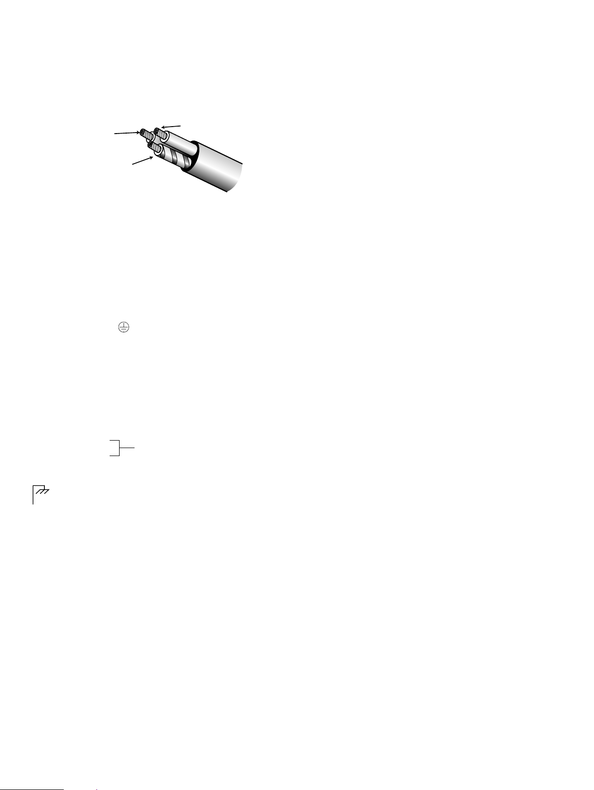
Power Connector Wiring
brown = hot
blue =
neutral
yellow/green =
earth ground
(chassis)
Use the following AC cable wiring diagram to create international or special-purpose power connectors:
AC cable color code
If the colors referred to in the diagram don't correspond to the
terminals in your plug, use the following guidelines:
• Connect the blue wire to the terminal marked with an
N or colored black.
• Connect the brown wire to the terminal marked with an
L or colored red.
• Connect the green and yellow wire to the terminal marked
with an E (or ) or colored green (or green and yellow).
presented by the paralleled input circuit. For most source
equipment it is safe to drive circuits whose input impedance
is no smaller than 10 times its output impedance. For example,
cascading 10 MSL-4s produces an input impedance of 1000
Ohms (10kΩ divided by 10). The source equipment should
have an output impedance of 100 ohms or less.
This is also true when connecting in parallel (loop out) MSL4s to 650-Ps, DS-4Ps, or any other Meyer Sound self-powered
loudspeaker system.
The LD-1A is highly recommended when driving systems
using multiple speakers. (See Measurement and Integration
Tools, page 9.)
Amplification and Protection Circuitry
Each driver in the MSL-4 is powered by one channel of the
Meyer Sound MP-2, a 1240W RMS amplifier (620W RMS/ch)
utilizing complementary power MOSFET output stages (class
AB/H). The following sections discuss the MP-2’s limiting
circuitry and the two-fan cooling system.
Audio Input
The MSL-4 presents a 10 kΩ balanced input impedance to a three-
pin XLR connector wired with the following convention:
Pin 1 — 220 kΩ to chassis and earth ground (ESD clamped)
Pin 2 — Signal
Pin 3 — Signal
Case — Earth (AC) ground and chassis
Shorting an input connector pin to the case can form a ground
loop and cause hum.
Pins 2 and 3 carry the input as a differential signal; their polarity can be reversed with the input polarity switch on the user
panel. If the switch is in the up position, pin 2 is hot relative
to pin 3, resulting in a positive pressure wave when a positive
signal is applied to pin 2. Use standard audio cables with XLR
connectors for balanced signal sources.
TROUBLESHOOTING NOTE: If abnormal noise (hum,
hiss, popping) is produced from the loudspeaker, disconnect
the audio source from the speaker. If the noise stops, then the
problem is not within the loudspeaker; check the audio input
and AC power.
A single source can drive multiple MSL-4s with a paralleled
input loop, creating an unbuffered hardwired loop connection.
The input impedance fo a single MSL-4 is 10kΩ; cascading
n MSL-4s will produce a balanced input impedance of 10kΩ
divided by n. To avoid distortion from the source, make sure
that the source equipment can drive the total load impedance
6
Differential Inputs
TruPower™ Limiting System
Conventional limiters assume that the resistance of a loudspeaker
remains constant and set the limiting threshold by measuring
voltage only. This method is inaccurate because the loudspeaker’s
resistance changes in response to the frequency content of the
source material and thermal variations in the loudspeaker’s
voice coil and magnet. Conventional limiters begin limiting
prematurely, which under-utilizes system headroom and deprives
the loudspeaker of its full dynamic range.
The TruPower limiting (TPL) system accounts for varying
loudpeaker impedance by measuring current, in addition
to voltage, to compute the power dissipation and voice coil
temperature. TPL improves performance during limiting by allowing the loudspeaker to produce its maximum SPL across its
entire frequency range and extends the lifetime of the drivers
by controlling the temperature of the voice coil.
HI Limit and LO Limit LEDs on the user panel indicate TPL
activity for the high and low frequency amplifier channels. When
either channel exceeds the safe continuous power level, its limiter
engages, ceasing operation when the power level returns to normal.
The limiters for each channel function independently and do
not affect the signal when the LEDs are inactive.
The MSL-4 performs within its acoustical specifications and
operates at a normal temperature if the limit LEDs are on for no
 Loading...