

Page 1
Meyer Sound Laboratories, Inc.
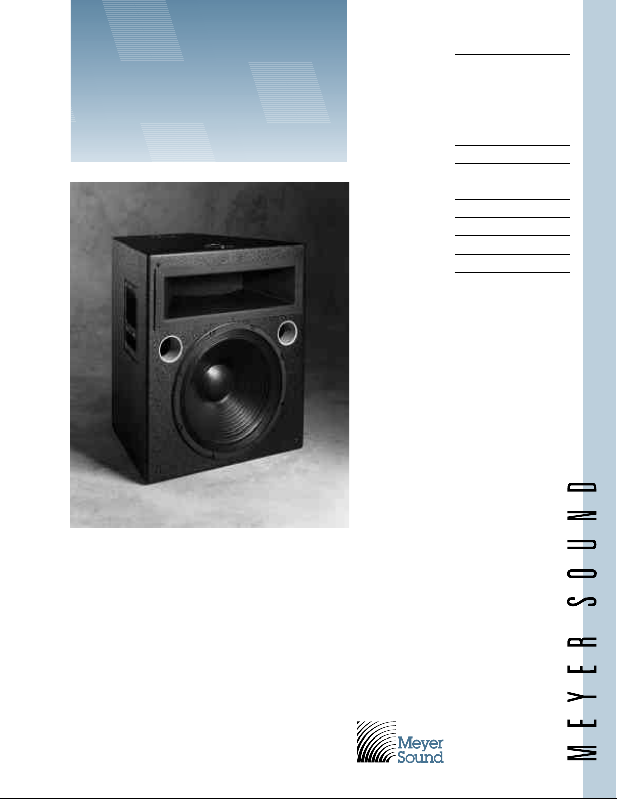
The MSL-2A is a high-powered, wide-
voltage gain of 10␣dB (minimum) to 32␣dB
Features
MSL-2A
High Power
Loudspeaker
Efficient high power
Arrayable
Wide horizontal coverage
Flat frequency response
Rugged and reliable
Applications
Touring reinforcement
Live music clubs
Theatre PA systems
Side fill in concert reinforcement
High powered announcing
Music playback in discos
coverage loudspeaker for professional
sound reinforcement applications. Specifically designed for touring reinforcement,
the accurate, rugged MSL-2A is a biamplified system consisting of a proprietary 15inch low-frequency driver in a vented enclosure, and a 70-degree high-frequency
horn with 2-inch (throat diameter) driver.
The MSL-2A’s drivers provide exceptional efficiency and power handling, with
low distortion for maximum clarity.
— 12
–
–
— 9
–
–
— 6
–
–
— 3
–
–
— 0
Inches
The sturdy, multi-ply hardwood enclosure with textured finish is designed to
withstand road abuse. The MSL-2A comes
with handles and, optionally, aircraft-style
rigging pan fittings or nut plates.
The MSL-2A requires a high-quality
professional stereo power amplifier capable
of delivering up to 600 watts per channel
continuously into 8 ohms, with a signal
(maximum).
2832 San Pablo Avenue
Berkeley, CA 94702
(510) 486-1166
FAX (510) 486-8356
Page 2

MSL-2A Specifications
Acoustical – MSL-2A/S-1 System
Frequency Response
Maximum SPL
1
2
40 Hz to 18 kHz +4 dB
Continuous 130 dB
Peak 139 dB
Maximum Peak (Music Signal) 144 dB
HF Coverage, -6dB points 70° horizontal x 60° vertical
Acoustical Crossover Frequency 900 Hz
MSL-2A Loudspeaker
Transducers
Low Frequency MS-15 15-inch cone driver, 8 ohms
High Frequency MS-2001A 2-inch throat compression driver, 8 ohms
High-Frequency Horn 70 degree modified radial
HF Network DC blocking capacitor
Enclosure 2.3 cu. ft. vented, multi-ply Finnish birch plywood
Finish Black textured
Protective Grill Hex perforated metal, powder coated, charcoal-
grey foam covering
Connector EP-4 male (EP-5 male, Europe only)
Rigging (optional) Aircraft pan fittings,
Physical Dimensions 21
1
⁄4" W x 241⁄4" H x 181/4" D
3
⁄8"-16 or M10 x 1.5 nut plates
Weight 82 lbs. (37 kg)
S-1 Control Electronics Unit
Input Type
3
Active balanced ISO™ input, 10k ohms, 5k ohms per leg
Output Type Active push-pull, will drive 600 ohms
Maximum Input/Output Level
Balanced +26 dBu
Unbalanced +20 dBu
Hum and Noise
Dynamic Range 108 dB
Sense Inputs 100k ohms true differential
Low-Frequency Delay Type Active all-pass
Driver Protection Circuitry
Low Frequency RMS limiter and excursion limiter
High Frequency RMS limiter and excursion limiter
Indicators
Sense/Gain Detect, Hi and Lo Red /Green LEDs
Limit, Hi, Lo, and VHF Red LEDs
Safe Green LED
Power Supply Green LED
Controls
Front Panel Input attenuator, AC power switch
Preset Panel Lo Cut switch, Safe switch, VHF switch, VHF control
Connectors
Balanced Inputs/Outputs 3-pin XLR (A-3)
Sense Inputs Banana jacks
Power 90-125/180-250V AC, 50/60 Hz (rear-panel switchable)
Physical Dimensions 19" W x 1
Weight 8 lbs. (3.6 kg)
4
<-90 dBV
Note 1:
Measured 1 meter on-axis to
high horn, half-space con–
ditions, pink noise input, in
third-octave bands.
Note 2:
VHF Peak limiter
Loudspeaker driven with “A”
weighted noise (peak-to-RMS
ratio
rated at 600 W/channel at
8␣ohms. The MSL-2A will accommodate amplifiers capable
of output levels up to
Note 3:
ISO™ input: Pins 1, 2 and 3 are
transformer isolated, shell is
connected to chassis/AC mains
ground.
3
⁄4" H x 73⁄4" D standard rack mount
Note 4:
“A”- weighted, unbalanced.
≈
12 dB), with amplifier
±
140 vpk.
Page 3

The S-1 Control
UltraSeries™ S-1
Power
Sense Limit
Safe
Adj
Lo Cut
Cal
VHF
Var
Safe
∞
20
10
8
4
3
2
1
0
Attn dB
5
6
-
Lo
Hi
VHF
Electronics Unit
The MSL-2A operates as a system with
the S-1 Control Electronics Unit (one per
channel). A single-channel device operating
at line level, the S-1 is the final component
in the signal chain before the amplifier.
Optimized for the MSL-2A loudspeaker
and pre-aligned at the factory, the S-1
contains frequency and phase response
alignment circuitry, and Meyer Sound’s
exclusive SpeakerSense
™
driver protection
circuitry, incorporating both peak and RMS
signal limiting as well as excursion protection.
SpeakerSense driver protection circuitry
protects the MSL-2A loudspeaker components from damage due to overheating or
excessive excursion under high power conditions. This unique circuit continuously
monitors the power applied to the MSL-2A
drivers, and individually limits the highfrequency and low-frequency outputs when
the safe operating limits of the drivers are
exceeded. Until the onset of overload, the
SpeakerSense circuitry has no effect on the
signal.
The S-1 SpeakerSense circuit incorporates Meyer Sound’s new MultiSense™
function, which allows the use of multiple
power amplifiers having different channel
gains and/or power ratings. The S-1 accommodates two stereo power amplifiers, and
provides separate Sense inputs for each. Its
MultiSense circuit, which implements an
analog OR condition, automatically tracks
the power amplifier with the greatest output voltage swing to control the system
protection limiters.
To enhance the effectiveness of the
MSL-2A in stage monitoring applications,
the S-1 incorporates sliding filters which
band-limit the system response under fullpower conditions. This has the effect of discriminating for vocal information in the
signal to increase clarity.
Also provided is a switch-selectable Safeguard function, which widens the safety
margin of the system and is intended to be
used when extended periods of overload are
anticipated. The Safeguard switch and
other setup controls are located behind a
cover plate on the S-1 front panel, providing a means of securing the system
installer’s presets.
Page 4

Architectural and
into 8␣ohms shall meet the following
octave pink noise at 1␣meter on axis; output
in excess of 140␣dB SPL when driven with
60␣degrees vertical.
" D, weight 8 lb (3.6␣kg).
Array Examples
Physical Dimensions
8.75" 55°
18.25"
11.00"
12.75"
24.25"
18.25"
13.00"
21.25"
11.25"
Notes
Rigging Points
Top and Bottom
Grill (Not Shown)
Dimensions:
21.25" x 24.45" x 2"
Drawing Not To Scale
11.00"
Engineering Specifications MSL-2A/S-1
Meyer Sound Laboratories has
devoted itself to designing,
manufacturing, and refining com-
The compact speaker system shall be of
the two-way type, with a 15" low-frequency
loudspeaker front-mounted in a ducted
bass-reflex hardwood plywood enclosure,
a compression driver mounted on a highfrequency horn which has a 2.0" throat and
4.0" diameter diaphragm with gap field
strength of 19k Gauss, and a separate Control Electronics Unit.
The Control Electronics Unit shall contain a power supply capable of operating
from a 90-125/180-250V AC, 50/60 Hz line;
electronic crossover circuitry; electronic
delay for the phase alignment of the lowfrequency speaker; low- and high-frequency
protection filters which automatically activate under high power conditions;
RMS, peak and excursion limiters to protect the speaker components; equalization
circuitry; active balanced input; and indicator LEDs for power and limiters. Total harmonic distortion shall be less than 0.1%.
“A” weighted noise level shall be at least
110 dB below maximum rated output of
+26 dBu.
The speaker system, its companion
Control Electronics Unit, and a power
amplifier rated at up to 600 watts/channel
performance criteria: frequency response,
1
40 Hz to 18 kHz ±4 dB measured with
rd
/
3
of 130 dB SPL one meter on axis with peaks
“A”-weighted noise. High frequency
distribution, 70 degrees horizontal by
Speaker enclosure dimensions are
1
21
⁄4" W x 24 1⁄4" H x 18 1⁄4
" D, weight 82 lbs
(37 kg).
Control Electronics Unit dimensions are
3
19" W x 1
⁄4" H x 7 3⁄4
The speaker system shall be the Meyer
Sound MSL-2A.
The Control Electronics Unit shall be
the Meyer Sound S-1.
ponents that deliver superb sonic
reproduction. Every part of every
component is designed and built to
exacting specifications and
undergoes rigorous, comprehensive
testing in the laboratories.
Research remains an integral,
driving force behind all production.
Meyer strives for sound quality that
is predictable and neutral over an
extended lifetime and across an
extended range.
Coverage Angle (-6 dB)
Vertical 60 degrees
Horizontal 70 degrees
Maximum SPL @ 1meter
Continuous 130 dB
Peak 139 dB
Total Amplifier Power 1200 W
Narrow Horizontal Coverage Array
Coverage Angle (-6 dB)
Vertical 60 degrees
Horizontal 95 degrees
Maximum SPL @ 1meter
Continuous 136 dB
Peak 145 dB
Total Amplifier Power 2400 W
Optimal Horizontal Coverage Array
Coverage Angle (- 6 dB)
Vertical 60 degrees
Horizontal 120 degrees
Maximum SPL @ 1meter
Continuous 134 dB
Peak 143 dB
Total Amplifier Power 2400 W
©1994 Meyer Sound 04.011.013.01 B2
Sound
engineering
for the art
and science
of sound.
Meyer Sound Laboratories, Inc.
2832 San Pablo Avenue
Berkeley, CA 94702
(510) 486-1166
FAX (510) 486-8356
 Loading...