

Meyer Sound MJF-212A-3, MJF-212A-VEAM-RMS-3, MJF-212A-VEAM-3, MJF-212A-RMS, MJF-212A-ATTN/POL-3 Datasheet
DATASHEET
27.07
[688mm]
16.11
[409mm]
8.80
[223mm]
40¡
13.70
[348mm]
23.00
[584mm]
40¡
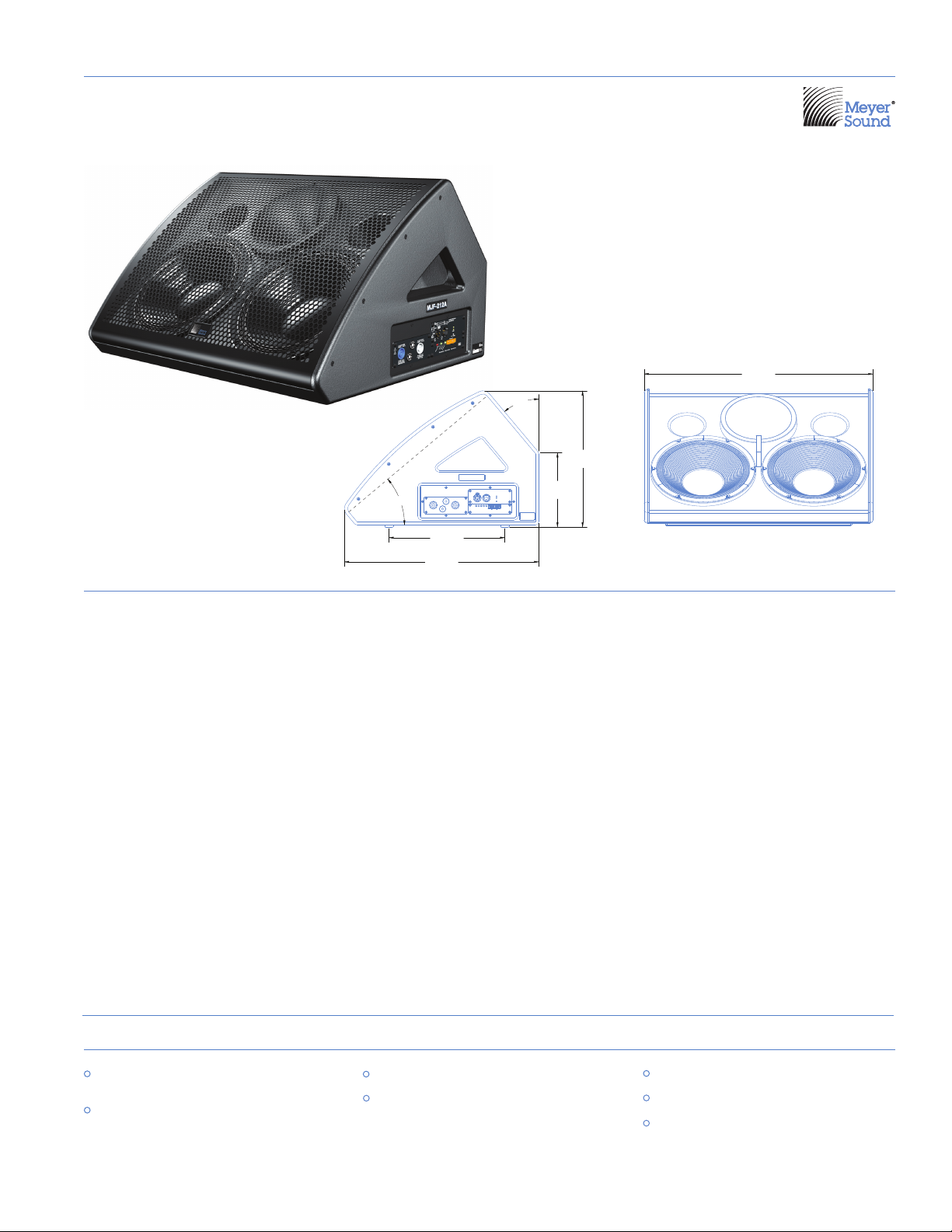
MJF-212A : High-Power Stage Monitor
ULTRASERIES
The Meyer Sound MJF-212A is a selfpowered stage monitor loudspeaker
designed to meet critical requirements
in professional applications. Exhibiting
flat amplitude and phase responses, fullrange bandwidth, and exceptional impulse
response, the MJF-212A far exceeds the
capabilities of conventional stage monitors
while offering the simplicity of setup and
operation provided by self-powered
systems.
The MJF-212A monitor’s phase-corrected
frequency range of 55 Hz to 18 kHz
enables accurate reproduction of both
vocals and instruments with high gain
before feedback, and provides excellent
intelligibility at high output levels with low
distortion and no coloration added to the
signal. The MJF-212A is also engineered
to have exceptional low-frequency
headroom, which can be helpful in some
Dimensions
Weight
Enclosure
Finish
Protective Grille
Audio Input
AC Power Connector
applications such as the extreme lowfrequency demands of high-level drum
monitoring. The face of the low-profile
cabinet slopes at 40 degrees from the stage
to permit optimal placement relative to the
talent, while its medium-Q horn provides
even coverage in both the horizontal and
vertical planes.
The loudspeaker’s high-frequency section
comprises a 4-inch diaphragm compression
driver coupled to a symmetrical (50 degrees
horizontal by 50 degrees vertical) constant
directivity horn. A pair of high-power
12-inch neodymium magnet cone drivers
with 4-inch voice coils, mounted in an
optimally vented enclosure, reproduces
low frequencies.
Each driver is powered by one channel of
a three-channel class AB/H amplifier that
employs complementary power MOSFET
27.07" w x 16.11" h x 23.00" d
(688 mm x 409 mm x 584 mm)
108 lbs (49 kg)
Premium birch plywood
Black textured
Powder-coated hex-stamped steel,
black mesh screen
Female XLR input with male XLR loop output or
VEAM all-in-one connector
PowerCon® with looping output or VEAM
all-in-one connector
output stages to provide total burst output
of 1275 watts (2 x 500 watts, 1 x 275 watts),
2550 watts total peak. The MJF-212A
incorporates Meyer Sound’s Intelligent AC™
system for automatic voltage selection, EMI
filtering, soft current turn-on, and surge
suppression.
The cabinet is constructed from premium
birch plywood and coated with a durable,
textured black finish. A metal grille lined with
acoustical black mesh protects the drivers.
The rugged MJF-212A includes plastic skids
on the bottom of the unit to prevent damage
to the enclosure or stage floor.
The MJF-212A can be integrated into Meyer
Sound’s RMS™ remote monitoring system
with the addition of an optional module.
RMS is a Windows-based computer application for monitoring the full range of amplifier and limiter operating parameters.
features & benefits
High peak power ensures excellent
transient response
Flat frequency and phase responses
afford high levels of gain before
feedback
Low profile preserves sightlines
Symmetrical, medium-Q pattern
provides even coverage
applications
Main vocal monitor
High-output drum or keyboard monitor
Sidefill monitor for small- to medium-scale
applications
MJF-212A specifications
European Office:
Meyer Sound Lab. GmbH
Carl Zeiss Strasse 13
56751 Polch, Germany
Made by Meyer Sound Laboratories
Berkeley, California USA
o
f
N
o
r
t
h
A
m
e
r
i
c
a
,
I
n
c
.
C
US
T
U
V
R
h
e
i
n
l
a
n
d
Acoustical
Operating Frequency Range
Frequency Response
Maximum Peak SPL
Coverage
Crossover
4
Transducers
Audio Input
Maximum Common Mode Range
Nominal Input Sensitivity
Amplifier
AC Power
Safety Agency Rated Operating Range
Turn-on and Turn-off Points
Current Draw: Idle Current
Max Long-Term Continuous Current (>10 sec)
Burst Current (<1 sec)
Ultimate Short-Term Peak Current Draw
RMS Network (optional)
Phase Response
Dynamic Range
Low Frequency
High Frequency
Type
Connectors
Input Impedance
Wiring
DC Blocking
CMRR
RF Filter
TIM Filter
Input Level
Type
Output Power
Total Output
THD, IM, TIM
Load Capacity
Cooling
Connector
Voltage Selection
Inrush Current
1
55 Hz - 18 kHz
2
60 Hz - 16 kHz ±4 dB
500 Hz - 16 kHz ±45°
3
139 dB
>110 dB
50° symmetrical
1600 Hz
Two high-power 12" cone drivers with neodymium magnets
Nominal impedance: 2 Ω
Voice coil size: 4"
Power handling capability: 1200 W (AES)
5
4" compression driver
Nominal impedance: 8 Ω
Voice coil size: 4"
Diaphragm size: 4"
Exit size: 1.5"
Power handling capability: 250 W (AES)
5
Differential, electronically balanced
±15 V DC, clamped to earth for voltage transient protection
Female XLR input with male XLR loop output or VEAM all-in-one
connector (integrates AC, audio, and network)
10 kΩ differential between pins 2 and 3
Pin 1: Chassis/earth through 220 kΩ, 1000 pF, 15 V clamp network to
provide virtual ground lift at audio frequencies
Pin 2: Signal +
Pin 3: Signal Case: Earth ground and chassis
Differential DC blocking up to max common mode voltage
>50 dB, typically 80 dB (50 Hz–500 Hz)
Common mode: 425 kHz; Differential mode: 142 kHz
Integral to signal processing (<80 kHz)
0 dBV (1 V rms, 1.4 V pk) continuous is typically the onset of limiting
for noise and music
Audio source must be capable of producing +20 dBV (10 V rms,
14 V pk) into 600 Ω in order to produce maximum peak SPL over the
operating bandwidth of the loudspeaker
Three-channel complementary MOSFET output stages (class AB/H)
6
1275 W (three channels; 2 x 500 W, 1 x 275 W)
7
2550 W peak
<.02%
2 Ω low channels; 8 Ω high channel
Convection
PowerCon with looping output or VEAM
Automatic, two ranges, each with high-low voltage tap
(uninterrupted)
95 V AC - 125 V AC; 208 V AC - 235 V AC, 50/60 Hz
85 V AC - 134 V AC; 165 V AC - 264 V AC
0.650 A rms (115 V AC); 0.310 A rms (230 V AC); 0.760 A rms (100 V AC)
4.67 A rms (115 V AC); 2.37 A rms (230 V AC); 5.25 A rms (100 V AC)
8
7.90 A rms (115 V AC); 4.10 A rms (230 V AC); 9.24 A rms (100 V AC)
20 A pk (115 V AC); 10 A pk (230 V AC); 21.8 A pk (100 V AC)
10 A pk (115 and 100 V AC); 18 A pk (230 V AC)
Equipped with two-conductor twisted-pair network, reporting all
operating parameters of amplifiers to system operator’s
host computer
Notes:
1. Recommended maximum operating
frequency range. Response depends
on loading conditions and room
acoustics.
2. Half-space loading measured with
1/3-octave frequency resolution at 4
meters.
3. Measured with music, half-space
loading, referred to 1 meter.
4. At this frequency, the transducers
produce equal sound pressure levels.
5. Power handling is measured under
AES standard conditions: transducers
driven continuously for two hours
with band limited noise signal having
a 6 dB peak-average ratio.
6. Amplifier wattage rating based on
the maximum unclipped burst sinewave rms voltage that the amplifier
will produce for at least 0.5 seconds
into the nominal load impedance.
7. Peak power based on the maximum
unclipped peak voltage that the
amplifier will produce for at least 100
milliseconds into the nominal load
impedance.
8. AC power cabling must be of sufficient
gauge so that under burst current rms
conditions, cable transmission losses
do not drop voltage below specified
operating range at the speaker.
MJF-212A - 04.157.004.03 A2
Copyright © 2007
Meyer Sound Laboratories Inc.
All rights reserved
meyer sound laboratories inc.
2832 San Pablo Avenue
Berkeley, CA 94702
T: +1 510 486.1166
F: +1 510 486.8356
techsupport@meyersound.com
www.meyersound.com
architect specifications
The loudspeaker shall be a self-powered stage monitor; the
transducers shall consist of two 12-inch diameter cone drivers
and a 4-inch diaphragm compression driver on a 50-degree
symmetrical horn. The loudspeaker system shall incorporate
internal processing electronics and a three-channel amplifier,
one channel for each driver. Processing functions shall include
equalization, phase correction, signal division, and protection
for the high- and low-frequency sections. The crossover point
shall be 1600 Hz.
Each amplifier channel shall be class AB/H with complementary
MOSFET output stages. Burst capability for the low-frequency
channels shall be 500 watts total with nominal 2-ohm resistive
load and 275 watts for the high-frequency channel with
nominal 8-ohm resistive load. Peak power shall be 2550 watts.
Distortion (THD, IM, TIM) shall not exceed 0.02%.
Performance specifications for a typical production unit shall
be as follows, measured at 1/3-octave resolution: Operating
frequency range shall be 55 Hz to 18 kHz. Phase response shall
be ±45° from 500 Hz to 16 kHz. Maximum peak SPL shall be
139 dB at 1 meter, half-space loading. Coverage shall be 50
degrees by 50 degrees.
The audio input shall be electronically balanced with a 10 kOhm
impedance and accept a nominal 0 dBV (1 V rms, 1.4 V pk) signal.
Connector shall be XLR (A-3) type female with parallel looping
Male or VEAM all-in-one multipin connector. RF filtering shall
be provided, and CMRR shall be greater than 80 dB from 50 Hz
to 500 Hz. The internal power supply shall perform automatic
voltage selection, EMI filtering, soft current turn-on and surge
suppression. Powering requirements shall be nominal 100, 110
or 230 V AC line current at 50 or 60 Hz. UL and CE operating
voltage range shall be 100 to 240 V AC. Maximum peak current
draw during burst shall be 7.90 A at 115 V AC, 4.10 A at 230 V
AC, and 9.24 A at 100 V AC. Current inrush during soft turn-on
shall not exceed 10 A at 115 V AC. AC power connectors shall be
PowerCon with looping capabilities or VEAM all-in-one multipin connector.
The loudspeaker system shall provide facilities for installing
Meyer Sound’s optional RMS remote monitoring system. All
components shall be mounted in an acoustically vented wedgeshaped enclosure constructed of premium birch plywood with
a black textured hard-shell finish. The front grille shall be hex
stamped steel with black mesh screen. Dimensions shall be
27.07" wide x 16.11" high x 23.00" deep (688 mm x 409 mm x
584 mm). Weight shall be 108 lbs (49 kg). The enclosure front
angle shall be 40 degrees.
The loudspeaker shall be the Meyer Sound MJF-212A.
 Loading...