

Page 1
A variation on the popular MILO™ high-
power curvilinear loudspeaker, the MILO 60
high-power narrow coverage curvilinear
array loudspeaker excels where controlled
horizontal coverage is needed. The self-
powered MILO 60 is a compact, lightweight
four-way system that provides 60 degrees
of horizontal coverage, and vertical cover-
age matching the original MILO. The cover-
age pattern is optimized for applications
requiring tight horizontal cover age, such
as at the top in mixed arrays with standard
MILO or M3D line array loudspeaker sys-
tems, or for side fill hangs where keeping
sound off of side walls is important.
The MILO 60 shares the same dimensions
and rig ging components as the MILO and
MILO 120 expanded coverage high-power
curvilinear array loudspeakers to facilitate
seamless integration. The flexibility of the
MILO 60 allows it to be configured with
other Meyer Sound loud speakers in com-
plex systems. MILO 60 arrays and combined
Curvilinear Array Loudspeaker
DAT A S HEET
arrays with other M Series models are easy
to deploy using the MILO QuickFly
rigging
accessories, such as the MG-3D/M multi-
array tilt is easy to adjust, often elimi nating
the need for a pullback strap in flown con-
figurations.
SPL with exceptionally flat phase and fre-
cy section (4.2 kHz to 18 kHz) that renders
delicate transient information with detailed
acoustical charac teristics are designed to
facilitate seamless integration when used
with other MILO cur vilinear array elements.
A combined MILO 60/MILO/MILO 120 array
with M3D-Subs affords the precise low-
M S E RIE S
frequency directional control that has won
widespread acclaim for M3D systems. The
erage pattern to 30 Hz, assuring that very
the stage or cause excessive reverberation.
ation, a MILO array can be flown adjacent to
or ground stacked with 700-HP subwoofers.
The 700-HP's power and bandwidth handle
treme transient informa tion with minimal
distortion in its operating frequency range.
system is fitted as standard, providing com-
A weather-protected version with a folding
optionally available.
applications
Stadiums, arenas, concert halls and
theatres
Touring sound reinforcement
features & benefits
Controlled horizontal coverage angle of 60
degrees
dramatically minimize distortion
assure clean, high-impact response
Seamless integration with other M Series
QuickFly rigging system simplifies use in
flown or ground-stacked arrays
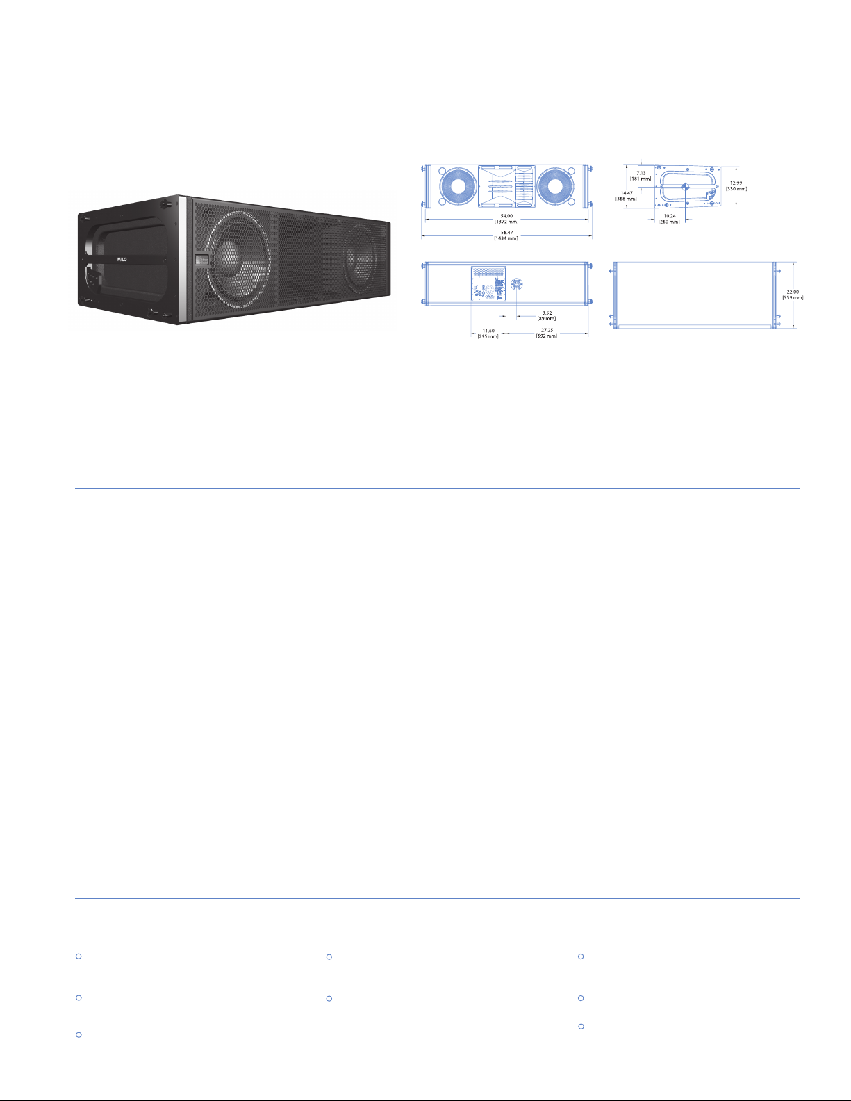
54.00" w x 14.47" h x 22.00" d
Black textured
Powder-coated hex-stamped steel
connectors and quick release pins
�
�
�
�
�
�
�
�
�
�
MILO 60 :
Dimensions
Weight
Enclosure
Finish
Protective Grille
Rigging
Page 2
1. The low-frequency power response of
the system will increase according to
the length of the array.
2. Recommended maximum operating
frequency range. Response depends
upon loading conditions and room
acoustics.
3. Free field, measured with 1/3 octave
frequency resolution at 4 meters.
4. Measured with music at 1 meter.
5. At these frequencies, the transducers
produce equal sound pressure levels:
560 Hz for the low-mid and mid-high
and 4.2 kHz for the mid-high and
very-high frequency drivers.
6. Power handling is measured under
AES standard conditions: transducer
driven continuously for two hours with
band limited noise signal having a 6 dB
peak-average ratio.
7. To eliminate interference at short
wavelengths, the two 12-inch cone
drivers work in combination at low
frequencies (60 Hz – 300 Hz). At mid
frequencies (300 Hz – 560 Hz) only one
cone driver is fed from the crossover
to maintain optimal polar and
frequency response characteristics.
8. The three drivers are coupled to a
constant-directivity horn through
a proprietary acoustical combining
manifold (REM).
9. Amplifier wattage rating is based
on the maximum unclipped burst
sine-wave rms voltage the amplifier
will produce in to the nominal load
impedance. Low, low-mid and very-
high frequency channels 67 V rms (95
channel 67 V rms (95 V pk) into 8 ohms.
10. AC power cabling must be of sufficient
gauge so that under burst current rms
conditions, cable transmission losses
do not drop voltage below specified
operating range at the speaker.
meyer sound laboratories inc.
2832 San Pablo Avenue
Berkeley, CA 94702
T: +1 510 486.1166
F: +1 510 486.8356
techsupport@meyersound.com
www.meyersound.com
MILO 60 - 04.132.096.02 A
Copyright © 2004
Meyer Sound Laboratories Inc.
Operating Frequency Range
60 Hz - 18 kHz
65 Hz - 17.5 kHz ±4 dB
750 Hz - 16 kHz ±30°
140 dB
>110 dB
60° horiz.; vertical
varies depending on array length & configuration
560 Hz, 4.2 kHz
Two 12" cone drivers with neodymium magnets
Nominal impedance: 4
Ω
Voice coil size: 4"
Power-handling capability: 1200 W (AES)
6
One 4" compression driver
Nominal impedance: 8
Ω
Voice coil size: 4"
Diaphragm size: 4"
Exit size: 1.5"
Power handling capability: 250 W (AES)
6
on REM
Three 2" compression drivers
Nominal impedance: 12
Voice coil size: 2"
Diaphragm size: 2"
Exit size: 0.75"
Power handling capability: 100 W (AES)
6
on REM
Differential, electronically balanced
Female XLR input with male XLR loop output or VEAMall-in-one
connector (integrates AC, audio and network)
10 k
Ω
differential between pins 2 and 3
Pin 1: Chassis/earth through 220 k
, 1000 pF, 15 V clamp network to
provide virtual ground lift at audiofrequencies
Pin 2: Signal +
Pin 3: Signal -
Case: Earth ground and chassis
None on input, DC blocked through signal processing
>50 dB, typically 80 dB (50 Hz–500 Hz)
Common mode: 425 kHz
Differential mode: 142 kHz
0 dBV (1 V rms, 1.4 V pk) continuous is typically the onset of limiting
for noise and music
Audio source must be capable of producing a minimum of +20 dBV
Ω
inorder to produce maximum peak
SPL over the operating bandwidth of the loudspeaker
Complementary power MOSFET output stages (class AB/H)
3935 W (four channels; three x 1125 W, one x 560 W)
9
<.02%
4
Ω
low, low-mid and very-high channels; 8
Ω
mid-high channel
Forced air cooling, four fans (two ultrahigh-speed reserve fans)
Automatic, two ranges, each with high-low voltage tap
95 V AC – 125 V AC, 208 V AC - 235 V AC; 50/60 Hz
85 V AC – 134 V AC; 165 V AC - 264 V AC
1.1 A rms (115 V AC);0.55 A rms (230 V AC);1.3 A rms (100 V AC)
11.2 A rms (115 V AC);5.6 A rms (230 V AC);12.9 A rms (100 V AC)
14.4 A rms (115 V AC);7.2 A rms (230 V AC);16.6 A rms (100 V AC)
32 A pk (115 V AC);16 A pk (230 V AC);37 A pk (100 V AC)
7 A (115 V AC and 110 V AC); 10 A (230 V AC)
Equipped for two conductor twisted-pair network, reporting amplifier
operating parameters to system operator’s host computer.
Notes
European Office:
Meyer Sound Lab. GmbH
Carl Zeiss Strasse 13
56751 Polch, Germany
Made by Meyer Sound Laboratories
Berkeley,California USA
architect specifications
The loudspeaker shall be a self-powered, full-range unit for
deployment in line array systems. The low/low-mid frequency
transducers shall consist of two 12-inch cone drivers, each
rated to handle 1200 watts AES*. The mid-high frequency
transducer shall be one 4-inch diaphragm (1.5-inch exit) com-
pression driver, rated to handle 250 watts AES, coupled via a
custom manifold to a 60° horizontal constant directivity horn.
The very-high frequency transducers shall consist of three
2-inch diaphragm (0.75-inch exit) compression drivers, each
rated to handle 100 watts AES, coupled via a patented custom
manifold to a 60° horizontal constant directivity horn.
The loudspeaker shall incorporate internal processing electron-
ics and a four-channel amplifier. Processing functions shall
include equalization, phase correction, driver protection and
signal division for the three frequency sections. The crossover
points shall be 560 Hz and 4.2 kHz. An additional low-fre-
quency crossover shall cause the two low/low-mid frequency
transducers to work in combination between 60 Hz and 300 Hz,
with only one working between 300 Hz and 560 Hz, to maintain
optimal polar response characteristics.
Each amplifier channel shall be class AB/H with complementary
MOSFET output stages. Burst capability shall be 3935 watts total
(three channels 1125 watts, one channel 560 watts) with a
nominal 4-ohm load for low, low-mid and very-high frequency
channels and an 8-ohm load for the mid-high frequency chan-
nel. Distortion (THD, IM, TIM) shall not exceed 0.02%. Protection
circuits shall include TruPower limiting. The audio input shall be
electronically balanced with a 10 kOhm impedance and accept
a nominal 0 dBV (1 V rms, 1.4 V pk) signal (+20 dBV to produce
maximum SPL). Connectors shall be XLR (A-3) type male and
female. RF filtering shall be provided. CMRR shall be greater
than 50 dB (typically 80 dB 50 Hz – 500 Hz).
Performance specifications for a typical production unit shall be
as follows, measured at 1/3 octave resolution: Operating fre-
quency range shall be 60 Hz to 18 kHz. Phase response shall be
at 1 meter. Beamwidth shall be 60° horizontal. Vertical cover-
age in multi-cabinet arrays shall be dependent on system con-
figuration. The internal power supply shall perform automatic
voltage selection, EMI filtering, soft current turn-on and surge
suppression. Powering requirements shall be nominal 100, 110
or 230 V AC line current at 50 Hz or 60 Hz. UL and CE operating
voltage range shall be 100 to 240 V AC. Maximum peak current
draw during burst shall be 14.4 A at 115 V AC and 7.2 A at 230
V AC. Current inrush during soft turn-on shall not exceed 7 A
at 115 V AC. AC power connectors shall be locking NEMA con-
nector, IEC male or VEAM all-in-one. The loudspeaker system
shall incorporate the electronics module for Meyer Sound’s RMS
remote monitoring system.
All loudspeaker components shall be mounted in an enclosure
constructed of multi-ply hardwood with a hard black textured
finish. The front protective grille shall be powder-coated, hex-
stamped steel. Dimensions shall be 54.00" wide x 14.47" high
(cabinet front) x 22.00" deep (1372 mm x 368 mm x 559 mm).
Weight shall be 235 lbs (106.60 kg).
The loudspeaker shall be the Meyer Sound MILO 60.
*Loudspeaker driven with a band-limited noise signal with 6 dB
peak-to-average ratio for a period of two hours.
Acoustical
Coverage
Crossover
Crossover
5
Transducer s
Transducer s
Audio I nput
Amplifier
AC Power
RMS Net work
RMS Net work
Frequency Response
Phase Response
Maximum Peak SPL
Dynamic Range
Horizontal Coverage
2
3
4
Low/Low-Mid Frequency
Mid-High Frequency
Very-High Frequency
Maximum Common Mode Range
Input Impedance
Nominal Input Sensitivity
Type
Connectors
Wiring
DC Blocking
CMRR
RF Filter
TIM Filter
Input Level
7
8
Type
Output Power
THD, IM, TIM
Load Capacity
Cooling
Automatic Voltage Selection
Safety Agency Rated Operating Range
Turn-on and Turn-off Points
Max Long-Term Continuous Current (>10 sec)
Ultimate Short-Term Peak Current Draw
Burst Current (<1 sec)
Connector
Current Draw:
Idle Current
Inrush Current
10
 Loading...