

Page 1
DA T A S H E ET
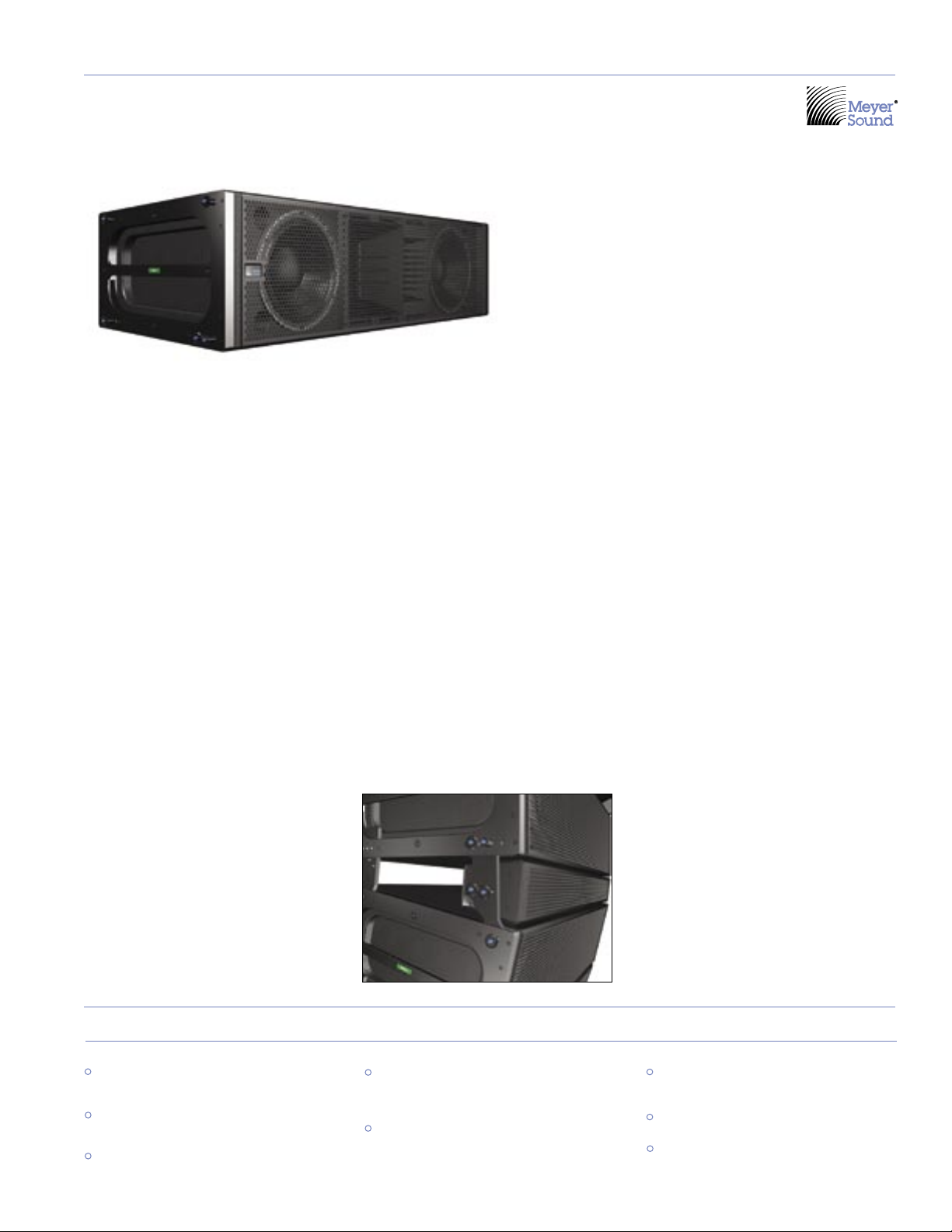
MILO 120 : High-Power Extended Coverage
Curvilinear Array Loudspeaker
M S E R I E S
A variation on the popular MILO™ highpower curvilinear loudspeaker, the MILO
120 high-power expanded coverage curvi
linear array loudspeaker excels where wide
horizontal and increased vertical coverage
are needed.
The self-powered MILO 120 is a compact,
lightweight four-way system that pro
vides 120 degrees of horizontal and 20
degrees of vertical coverage. The MILO 120
expanded coverage pattern is optimized for
medium to near field applications, making it
the perfect downfill complement for stan
dard MILO or M3D line array loudspeaker
systems. MILO 120 can also be used to
form wide coverage arrays or in other fill
applications that can be satisfied by one or
two cabinets.
As part of the M Series, the MILO 120
loudspeaker comes standard with Meyer
Sound’s RMS™ remote monitoring system.
The MILO 120 shares the same dimensions
as the standard MILO cabinet to facilitate
seamless integration with MILO and exist
ing MILO QuickFly
like the MG-3D/M multipurpose grid and
MCF-MILO caster frame. The flexibility of
MILO 120 also allows it to be configured
with other Meyer Sound loudspeakers in
complex systems.
®
rigging accessories,
MILO 120 produces a peak output of 138
dB SPL with exceptionally flat phase and
-
frequency response. Its wide operating
frequency range (60 Hz to 18 kHz) is com
plemented by extended high-frequency
headroom and a dedicated very-high fre
quency section (4.2 kHz to 18 kHz) that
renders delicate transient information with
-
detailed resolution through its wide cover
age pattern. The MILO 120 loudspeaker’s
acoustical characteristics are designed to
facilitate seamless integration when used
with other MILO curvilinear elements.
The optional MILO 120-I insert (shown
below) can be fitted to enhance the appear
ance of arrays which include the MILO 120,
and also provide acoustical benefits that
allow MILO and MILO 120 cabinets in the
same array to be fed with identical signals,
with no additional equalization.
-
Flown and ground-stacked MILO 120 arrays
and combined arrays with other M Series
(MILO/M3D/M3D-Subs) models are easy to
deploy using QuickFly components. Custom
front and rear AlignaLinks at the cabi
net corners couple the units for flying or
stacking, and allow from 13 to 19 degrees
of cabinet splay adjustable in two-degree
increments. Because rigging connections
are rigid, the array tilt is easy to adjust
– often eliminating the need for a pullback
strap in flown configurations.
A combined MILO/MILO 120 array with M3DSubs affords precise low-frequency direc
tional control that has won widespread
acclaim for M3D systems. The M3D-Sub
provides a well-controlled coverage pattern
to 30 Hz, assuring that very low-frequency
energy does not spill onto the stage or
cause excessive reverberation. In applica
tions where directional low-frequency con
trol is not primary, a MILO/MILO 120 array
can be flown adjacent to or ground stacked
with Meyer Sound 700-HP subwoofers. With
significantly more output than other “highpower” subwoofers, the Meyer Sound 700HP sets a new standard for the power-tosize equation. Its power and bandwidth
handle high continuous operating levels and
extreme transient information with minimal
distortion in its operating frequency range.
-
-
-
-
features & benefits
Extreme coverage angles of 120 degrees
(horizontal) and 20 degrees (vertical)
Exceptional fidelity and peak capability
assure clean, high-impact response
Seamless integration with other M Series
models
Optional MILO 120-I insert enhances
appearance of arrays and provides
acoustical benefits
QuickFly rigging system simplifies use in
flown or ground-stacked arrays
applications
Stadiums, arenas, concert halls and
theatres
Touring sound reinforcement
Large-scale events
Page 2
Architect Specifications
The loudspeaker shall be a self-powered, full-range
unit for deployment in line array systems. The low/
low-mid frequency transducers shall consist of two
12-inch cone drivers, each rated to handle 1200 watts
AES*. The mid-high frequency transducer shall be
one 4-inch diaphragm (1.5-inch exit) compression
driver, rated to handle 250 watts AES, coupled via a
custom manifold to a 120-degree horizontal constant
directivity horn. The very-high frequency transducers
shall consist of two 2-inch diaphragm (0.75-inch exit)
compression drivers, each rated to handle 100 watts
AES, coupled via a custom manifold to a 120-degree
horizontal constant directivity horn.
The loudspeaker shall incorporate internal processing
electronics and a four-channel amplifier. Processing
functions shall include equalization, phase correction,
driver protection and signal division for the three fre
quency sections. The crossover points shall be 560 Hz
and 4.2 kHz. An additional low-frequency crossover
shall cause the two low/low-mid frequency transduc
ers to work in combination between 60 Hz and 180 Hz,
with only one working between 180 Hz and 560 Hz, to
maintain optimal polar response characteristics.
Each amplifier channel shall be class AB/H with com
plementary MOSFET output stages. Burst capability
shall be (two channels 1125 watts, one channel 750
watts and one channel 560 watts) with a nominal 4ohm load for low and low-mid frequency channels, 6ohm load for very-high frequency channel and 8-ohm
load high-frequency channel. Distortion (THD, IM, TIM)
shall not exceed 0.02%. Protection circuits shall include
peak and TruPower limiting. The audio input shall be
electronically balanced with a 10 kOhm impedance and
accept a nominal 0 dBV (1 V rms, 1.4 V pk) signal (+20
dBV to produce maximum SPL). Connectors shall be
XLR (A-3) type male and female or VEAM all-in-one
(integrates AC, audio and network). RF filtering shall be
provided. CMRR shall be greater than 50 dB (typically
80 dB 50 Hz – 500 Hz).
Performance specifications for a typical production
unit shall be as follows, measured at 1/3 octave reso
lution: Operating frequency range shall be 60 Hz to
18 kHz. Phase response shall be ±30° from 750 Hz to
16 kHz. Maximum peak SPL shall be 138 dB at 1 meter.
Beamwidth shall be 120 degrees horizontal. Vertical
coverage in multi-cabinet arrays shall be dependent
on system configuration; for a single cabinet vertical
coverage shall be 20 degrees.
The internal power supply shall perform automatic
voltage selection, EMI filtering, soft current turn-on
and surge suppression. Powering requirements shall be
nominal 100 V, 110 V or 230 V AC line current at 50 Hz
or 60 Hz. UL and CE operating voltage ranges shall be
95 to 125 V AC and 208 to 235 V AC. Current draw dur
ing burst shall be 14.4 A at 115 V AC and 7.2 A at 230 V
AC. Current inrush during soft turn-on shall not exceed
7 A at 115 V AC. AC power connectors shall be locking
NEMA L6-20 connector, IEC 309 male or VEAM.
The loudspeaker system shall incorporate the elec
tronics module for Meyer Sound’s RMS remote moni
toring system.
All loudspeaker components shall be mounted in an
enclosure constructed of multi-ply hardwood with a
hard black textured finish. The front protective grille
shall be powder-coated, hex stamped steel.
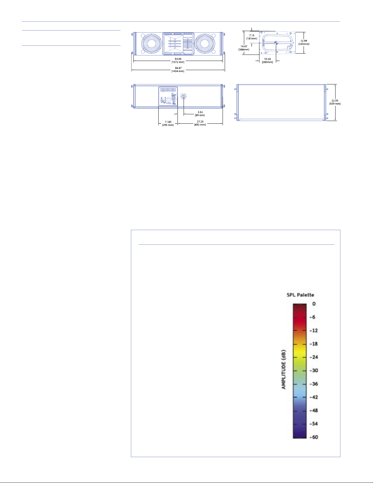
Dimensions shall be 54.00” wide x 14.47” high (cabinet
front) x 22.00” deep (1372 mm x 368 mm x 559 mm).
Weight shall be 235 lbs (106.60 kg).
The loudspeaker shall be the Meyer Sound MILO 120.
*Loudspeaker driven with a band-limited noise signal with 6 dB
peak-to-average ratio for a period of two hours.
-
-
Dimensions
54.00" w x 14.47" h x 22.00" d
(1372 mm x 368 mm x 559 mm)
Weight
235 lbs (106.60 kg)
Enclosure
-
Protective Grille
Rigging
Multi-ply hardwood
Finish
Black textured
Powder-coated hex stamped steel
MRF-MILO rigging frame, custom AlignaLink
connectors and quick release pins
About the Vertical Directivity Plots
The color images accompanying the upper diagram on the following page are sound
intensity plots made using the Meyer Sound MAPP Online
-
program, a unique and highly accurate visualization tool for professional sound
system designers.
Using an Internet-connected personal computer, the
designer specifies Meyer Sound loudspeaker models,
their locations, how they are aimed and, optionally,
the locations and composition of walls. This
information travels over the Internet to a powerful
server computer at Meyer Sound headquarters in
Berkeley, Calif. Running a sophisticated algorithm and
-
using highly accurate measured data that describe
each loudspeaker’s directional characteristics, the
server predicts the sound field that the loudspeakers
will produce, forms a color representation, and sends
-
-
the result back for the designer’s computer to display.
In these sound field plots, the color spectrum is used
to represent levels of sound intensity, with red being
the loudest and blue the softest, as shown in the scale
to the immediate right. These examples illustrate
coverage characteristics for an array whose splay
angles have been tailored to the actual venue whose
section view is superimposed on the MAPP Online
plots.
®
acoustical prediction
Page 3

Digital Delay
2 In x 6 Out
Digital Delay/EQ
LD-3
Channel A
IN SUB OUT
CH 1 OUT
CH 2 OUT
CH 3 OUT
Channel B
IN SUB OUT
CH 1 OUT
CH 2 OUT
CH 3 OUT
Channel A
INSERTS SENDS
IN SUB OUT
Full Range
IN CH 1 OUT
Post Array
IN CH 2 OUT
Post Array
IN CH 3 Post HPF
Channel B
INSERTS SENDS
IN SUB OUT
Full Range
IN CH 1 OUT
Post Array
IN CH 2 OUT
Post Array
IN CH 3 Post HPF
(10) MILO
(10) MILO
(2) MILO 120 (2) MILO 120
W/ MILO 120-I INSE
RTS
(OPTIONAL)
W/ MILO 120-I INSE
RTS
(OPTIONAL)
(6) 700-HP SUB
(6) 700-H
P SUB
MILO 120 Vertical Splay and Coverage
These illustrations show how the splay between adjacent
cabinets in a MILO/MILO 120 array may be adjusted to
tailor coverage for a specific venue. The MAPP Online
plots illustrate the vertical directivity characteristics of
this example array, with a section view of the venue
superimposed.
The top six cabinets (MILO) are splayed at small angles to
throw farther through coupling and cover the back of the
venue. The bottom two cabinets (MILO 120) are splayed at
wider angles to better cover the near field.
Signal Flow for a Typical
Integrated Reinforcement System
Because the MILO 120 loudspeaker is compatible with most other Meyer Sound reinforcement loudspeakers, sound designers have maximum
freedom to customize systems for their needs. This block diagram illustrates the signal flow for a typical integrated sound reinforcement
system using 10 MILO cabinets per side for the main arrays, and two MILO 120 loudspeakers used as downfill.
Page 4

MILO 120 Specifications
European Office:
Meyer Sound Lab. GmbH
Carl Zeiss Strasse 13
56751 Polch, Germany
Made by Meyer SoundLaboratories
Berkeley,California USA
Acoustical
Coverage
Crossover
Transducer s
Audio I nput
Amplifiers
AC Power
RMS Net work
1
Operating Frequency Range
Free Field Frequency Response
Maximum Peak SPL
Horizontal Coverage
Vertical Coverage
5
Low/Low-Mid Frequency
Mid-High Frequency
Very-High Frequency
Maximum Common Mode Range
Nominal Input Sensitivity
Automatic Voltage Selection
Safety Agency Rated Operating Range
Turn-on and Turn-off Points
Max Long-Term Continuous Current (>10 sec)
Burst Current (<1 sec)
Ultimate Short-Term Peak Current Draw
Phase Response
Dynamic Range
Type
Connectors
Input Impedance
Wiring
DC Blocking
CMRR
RF Filter
TIM Filter
Input Level
Type
Output Power
THD, IM, TIM
Load Capacity
Cooling
Connector
Current Draw:
Idle Current
Inrush Current
2
60 Hz - 18 kHz
3
65 Hz - 17.5 kHz ±4 dB
750 Hz - 16 kHz ±30°
4
138 dB
>110 dB
120°
Varies, depending on array length and configuration; 20° for
single loudspeaker
560 Hz, 4.2 kHz
7
Two 12" cone drivers with neodymium magnets
Nominal impedance: 4
Voice coil size: 4"
Power-handling capability: 1200 W (AES)
Ω
6
One 4" compression driver
Nominal impedance: 8 Ω
Voice coil size: 4"
Diaphragm size: 4"
Exit size: 1.5"
Power handling capability: 250 W (AES)6 on REM
8
Two 2" compression drivers
Nominal impedance: 12 Ω
Voice coil size: 2"
Diaphragm size: 2"
Exit size: 0.75"
Power handling capability: 100 W (AES)6on REM
Differential, electronically balanced
±15 V DC, clamped to earth for voltage transient protection
Female XLR input with male XLR loop output or VEAMall-in-one
connector (integrates AC, audio and network)
10 kΩ differential between pins 2 and 3
Pin 1: Chassis/earth through 220 kΩ, 1000 pF, 15 V clamp network
to provide virtual ground lift at audiofrequencies
Pin 2: Signal +
Pin 3: Signal -
Case: Earth ground and chassis
None on input, DC blocked through signal processing
>50 dB, typically 80 dB (50 Hz–500 Hz)
Common mode: 425 kHz
Differential mode: 142 kHz
Integral to signal processing (<80 kHz)
0 dBV (1 V rms, 1.4 V pk) continuous is typically the onset of
limiting for noise and music
Audio source must be capable of producing a minimum of +20 dBV
(10 V rms, 14 V pk) into 600 Ω inorder to produce maximum peak
SPL over the operating bandwidth of the loudspeaker
Complementary power MOSFET output stages (class AB/H)
3560 W (1125 W x 2 channels, 750 W x 1 channel, 560 W 1 x
channel)9
<.02%
4 Ω low and low-mid, 8 Ω mid, 6 Ω very-high channel
Forced air cooling, four fans (two ultrahigh-speed reserve fans)
250 V AC NEMA L6-20 (twistlock) inlet, IEC 309 male inlet, or VEAM
Automatic, two ranges, each with high-low voltage tap
95 V AC – 125 V AC, 208 V AC - 235 V AC; 50/60 Hz
85 V AC – 134 V AC; 165 V AC - 264 V AC
1.1 A rms (115 V AC);0.55 A rms (230 V AC);1.3 A rms (100 V AC)
11.2 A rms (115 V AC);5.6 A rms (230 V AC);12.9 A rms (100 V AC)
10
14.4 A rms (115 V AC);7.2 A rms (230 V AC);16.6 A rms (100 V AC)
32 A pk (115 V AC);16 A pk (230 V AC);37 A pk (100 V AC)
7 A (115 V AC and 110 V AC); 10 A (230 V AC)
Equipped for two conductor twisted-pair network, reporting all
operating parameters ofamplifiers to operator’s host computer.
:
Notes
1. The low-frequency power response of
the system will increase according to
the length of the array.
2. Recommended maximum operating
frequency range. Response depends
upon loading conditions and room
acoustics.
3. Measured with 1/3 octave frequency
resolution at 4 meters.
4. Measured with music at 1 meter.
5. At these frequencies, the transducers
produce equal sound pressure levels:
560 Hz for the low-mid and mid-high
and 4.2 kHz for the mid-high and
very-high frequency drivers.
6. Power handling is measured under
AES standard conditions: transducer
driven continuously for two hours with
band limited noise signal having a 6 dB
peak-average ratio.
7. To eliminate interference at short
wavelengths, the two 12-inch
drivers work in combination at low
frequencies (60 Hz – 180 Hz). At mid
frequencies (180 Hz – 560 Hz) only one
cone driver is fed from the crossover
to maintain optimal polar and
frequency response characteristics.
8. The three drivers are coupled to a
constant-directivity horn through
a proprietary acoustical combining
manifold (REM).
9. Amplifier wattage rating is based
on the maximum unclipped burst
sine-wave rms voltage the amplifier
will produce in to the nominal load
impedance low, mid and very high
channels 67 V rms (95 V pk) into 4, 6
and 8 ohms.
10. AC power cabling must be of sufficient
gauge so that under burst current RMS
conditions, cable transmission losses
do not drop voltage below specified
operating range at the speaker.
MILO 120 - 04.142.003.01 A
Copyright ©2004
Meyer Sound Laboratories Inc.
meyer sound laboratories inc.
2832 San Pablo Avenue
Berkeley, CA 94702
T: +1 510 486.1166
F: +1 510 486.8356
techsupport@meyersound.com
www.meyersound.com
 Loading...