

Page 1
DA T AS H EE T
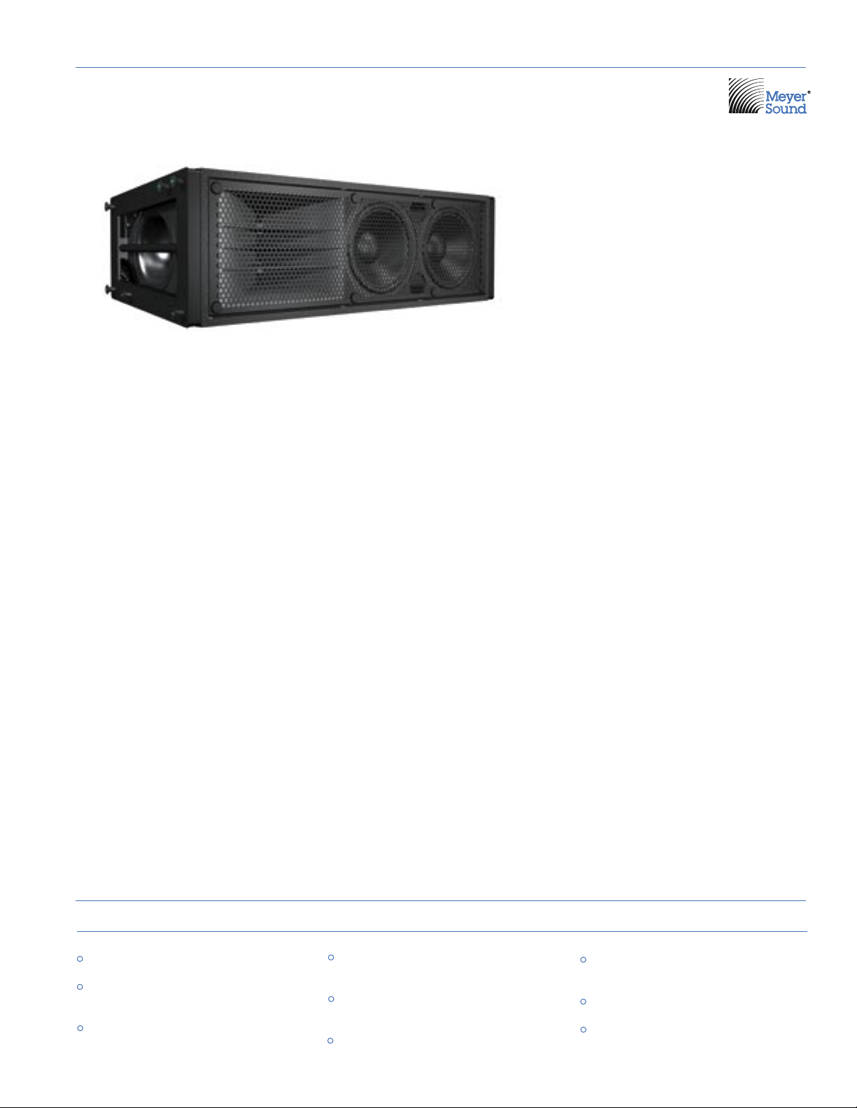
M2D : Compact Curvilinear Array Loudspeaker
M SE R IE S
The M2D™ compact curvilinear array loudspeaker brings numerous advantages to
mid-sized venues that require tight vertical pattern control with medium-to-long
throw. Its operating frequency range is 60
Hz to 16 kHz, with maximum peak output of
136 dB SPL (each cabinet) at 1 meter.
The M2D is designed for implementing vertical curvilinear arrays of up to 16 cabinets
with 1- to 7-degree splay between adjacent
units. For maximum leeway in configuring
systems, the M2D is fully compatible with
other M Series models and many Concert
Series and UltraSeries™ loudspeakers.
The M2D uses Meyer Sound’s patented
REM™ ribbon emulation manifold to couple
a single Meyer Sound 4-inch diaphragm
(1.5-inch exit) compression driver to a 90degree horn with constant-directivity horizontal coverage. REM controls the output of
the compression driver and introduces it to
the horn throat within a 3-inch path length,
dramatically reducing distortion. The unique
M2D horn design produces a coherent wave
front that is characteristic of – but much
more powerful than – a large ribbon driver.
(Vertical coverage depends upon array
length and curvature.)
The M2D's low-mid section comprises two
Meyer Sound 10-inch cone drivers with
lightweight neodymium magnet assemblies
housed in a compact, vented trapezoidal
enclosure. The M2D enclosure is constructed of multi-ply hardwood and coated with
a textured black finish. Integral metal grilles
protect the drivers. A weather-protected
version with custom rain hood to protect
the electronics is optionally available.
To assure the smoothest response in the
midrange, the M2D incorporates a complex
crossover design; at the lowest frequencies,
both 10-inch drivers combine to reproduce
powerful, coherent bass, while in the mid
frequencies the crossover feeds only one of
the two drivers. This technique eliminates
interference between the drivers that would
otherwise occur at shorter wavelengths,
and maintains optimal polar and frequency
response characteristics.
The self-powered, biamplified M2D incorporates a complementary MOSFET power
amplifier with 700 watts burst capability, together with active crossover and
optimized frequency and phase response
correction circuitry. Its Intelligent AC™
system performs automatic voltage selec-
tion, allowing the unit to accommodate
mains voltages in the range of 90 to
265 V AC at 50 or 60 Hz and additionally
provides EMI filtering, soft current turn-on
and surge suppression. Integral peak and
rms limiters protect the loudspeaker components from over-excursion and overheating. Phase-corrected active processing
circuits help maintain excellent performance
and reliability, and the high common-mode
rejection of the laser-trimmed differential
input permits long signal runs through a
simple shielded twisted pair cable.
QuickFly® rigging, fitted as standard,
employs entirely captive hardware and
allows flying up to 16 cabinets with a 7:1
safety factor. The optional MG-2D multipurpose grid allows loudspeakers to be flown
or ground stacked. The M2D features Meyer
Sound’s RMS™ remote monitoring system,
which allows the full range of operating
parameters to be monitored continuously
over a network using a Windows computer.
The companion M2D-Sub compact subwoofer is also available to provide lowfrequency enhancement and extend overall
system power bandwidth and frequency
response to 30 Hz.
features & benefits
Extremely high power-to-size ratio
Ideal system for mid-sized applications, or
as downfill in larger venues
Optimized line array behavior provides
consistent response over long throws
Multiple vertical line arrays may be
splayed horizontally to broaden coverage
Self-powered for simplified setup and
increased reliability
Seamless integration with other M Series
models
applications
Concert halls, nightclubs and houses of
worship
Theatrical sound reinforcement
Portable and installed audio-visual
systems
Page 2
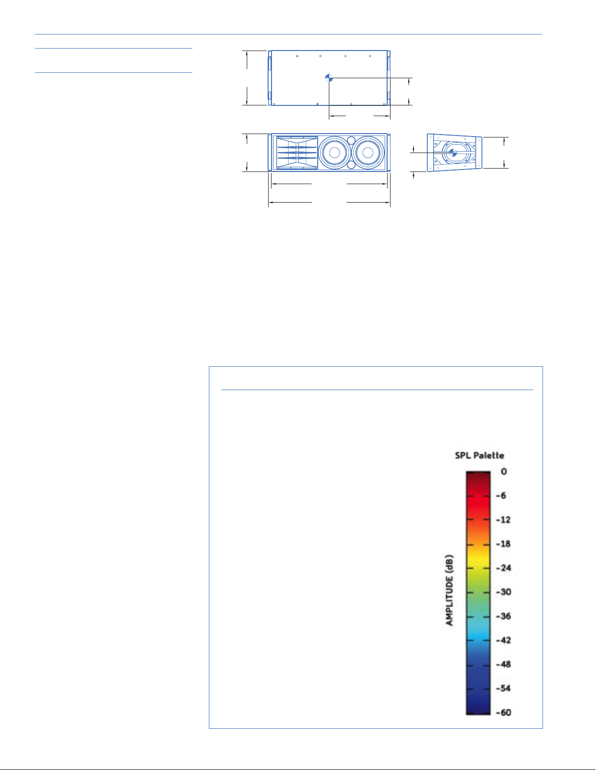
Architect Specifications
39.00
[991 mm]
37.00
[940 mm]
9.99
[254 mm]
12.12
[308 mm]
17.47
[444 mm]
6.06
[154 mm]
19.56
[497 mm]
8.74
[222 mm]
The loudspeaker shall be a self-powered, full-range
unit for deployment in line array systems. The lowfrequency transducers shall consist of two 10-inch
cone drivers with 2-inch voice coils rated to handle
400 AES watts* each. The high-frequency transducer
shall be one 4-inch diaphragm (1.5-inch exit)
compression driver, rated to handle 250 AES watts,
coupled via a custom REM manifold to a 90° horizontal
constant directivity horn.
The loudspeaker shall incorporate internal processing
electronics and a two-channel amplifier. Processing
functions shall include equalization, phase correction,
driver protection, and signal division for the highand low-frequency sections. The crossover point
(equal sound pressure levels between high- and lowfrequency transducers) shall be 575 Hz. An additional
low-frequency crossover shall cause the two
low-frequency transducers to work in combination
between 60 Hz and 350 Hz, with only one working
between 350 Hz and 575 Hz, to maintain optimal polar
response characteristics.
Each amplifier channel shall be class AB/bridged
with complementary MOSFET output stages. Burst
capability shall be 700 watts total with nominal 8-ohm
load for the high-frequency channel and 2 ohms for
the low-frequency channel. Distortion (THD, IM, TIM),
unloaded, shall not exceed 0.02%. Protection circuits
shall include peak and RMS limiters. The audio input
shall be electronically balanced with a 10-kOhm input
impedance and accept a nominal 0 dBV (1 V rms)
signal (20 dBV to produce maximum SPL). Connectors
shall be XLR (A-3) type male and female or VEAM. RF
filtering shall be provided, and CMRR shall be greater
than 50 dB (typically 80 dB, 50 – 500 Hz).
Performance specifications for a typical production
unit shall be as follows, measured at 1/3 octave
resolution: Operating frequency range shall be 60 Hz
to 16 kHz. Phase response shall be ±45° from 650 Hz to
12 kHz. Maximum peak SPL shall be 136 dB at 1 meter
with music. Beamwidth shall be 90°. Vertical coverage
in multi-cabinet arrays shall be dependent on system
configuration.
Dimensions
Enclosure
Protective Grille
Rigging
39.00" w x 12.12" h x 17.47" d
(991 mm x 308 mm x 444 mm)
Weight
116 lbs (52.62 kg); shipping: 130 lbs (58.97 kg)
Multi-ply hardwood
Finish
Black textured
Powder-coated hex stamped steel
Patented QuickFly MRF-2D rigging frame with
integral CamLinks™, rear connecting bars and
captive quick-release pins
About the Vertical Directivity Plots
The color images accompanying the upper diagram on the facing page are sound
intensity plots made using the Meyer Sound MAPP Online® acoustical prediction
program, a unique and highly accurate visualization tool for professional sound
system designers.
The internal power supply shall perform automatic
voltage selection, EMI filtering, soft current turn-on
and surge suppression. Powering requirements shall
be nominal 100, 110 or 230 V AC line current at 50 or
60 Hz. UL and CE operating voltage range shall be 100
to 240 V AC.
Maximum peak current draw during burst shall be 5.8
A at 115 V AC, 2.9 A at 230 V AC and 6.7 A at 100 V AC.
Current inrush during soft turn-on shall not exceed 9
A at 115 V AC. AC power connectors shall be locking
PowerCon or VEAM all-in-one muti-pin connector.
The loudspeaker system shall incorporate the
electronics module for Meyer Sound’s RMS remote
monitoring and control system.
All loudspeaker components shall be mounted in an
enclosure constructed of multi-ply hardwood with a
hard black textured finish. The front protective grille
shall be powder-coated, hex stamped steel.
Dimensions shall be 39.00" wide x 12.12" high x 17.47"
deep (991 mm x 308 mm x 444 mm). Weight shall be
116 lbs (52.62 kg).
The loudspeaker shall be the Meyer Sound M2D.
*Loudspeaker driven with a band-limited noise signal with 6 dB
peak-to-average ratio for a period of two hours.
Using an Internet-connected personal computer, the
designer specifies Meyer Sound loudspeaker models,
their locations, how they are aimed and, optionally,
the locations and composition of walls. This
information travels over the Internet to a powerful
server computer at Meyer Sound headquarters in
Berkeley, Calif. Running a sophisticated algorithm and
using highly accurate measured data that describe
each loudspeaker’s directional characteristics, the
server predicts the sound field that the loudspeakers
will produce, forms a color representation, and
sends the result back for the designer’s computer
to display.
In these sound field plots, the color spectrum is
used to represent levels of sound intensity, with
red being the loudest and blue the softest, as shown
in the scale to the immediate right. These examples
illustrate coverage characteristics for an array
whose splay angles have been tailored to the actual
venue whose section view is superimposed on the
MAPP Online plots.
Page 3

M2D Vertical Splay and Coverage
DigitalDelay
2 In x 6 Out
Digital Delay/EQ
LD-3
Channel A
IN SUB OUT
CH 1OUT
CH 2OUT
CH 3OUT
Channel B
IN SUB OUT
CH 1OUT
CH 2OUT
CH 3OUT
Channel A
INSERTS SENDS
IN SUB OUT
Full Range
IN CH1 OUT
PostArray
IN CH2 OUT
PostArray
IN CH3
Post HPF
Channel B
INSERTS SENDS
IN SUB OUT
Full Range
IN CH1 OUT
PostArray
IN CH2 OUT
PostArray
IN CH3
Post HPF
Main
Left
Right
Optional
Subwoofer
Mono
These illustrations show how the splay between adjacent cabinets in
an M2D array may be adjusted to tailor coverage for a specific venue.
The MAPP Online plots on the right illustrate the vertical directivity
characteristics of the array on the left, with a section view of the
venue superimposed.
Signal Flow for a Typical
Integrated Reinforcement System
Because the M2D is compatible with most other Meyer Sound reinforcement loudspeakers, sound designers have maximum freedom to
customize systems for their needs. This block diagram illustrates the signal flow for a typical integrated sound reinforcement system
using 12 M2Ds per side for the main arrays.
Page 4
M2D specifications
Acoustical
1
Operating Frequency Range
Frequency Response
Coverage
Horizontal Coverage
Crossover
Transducer s
Audio I nput
Maximum Common Mode Range
Nominal Input Sensitivity
Amplifier
AC Power
Safety Agency Rated Operating Range
Turn-on and Turn-off Points
Max Long-Term Continuous Current (>10 sec)
Burst Current (<1 sec)
Ultimate Short-Term Peak Current Draw
RMS Net work
Phase Response
Maximum Peak SPL
Dynamic Range
Vertical Coverage
Low/Mid Frequency
High Frequency
Type
Connectors
Input Impedance
Wiring
DC Blocking
CMRR
RF Filter
TIM Filter
Input Level
Type
Output Power
THD, IM, TIM
Load Capacity
Cooling
Connector
Voltage Selection
Current Draw:
Idle Current
Inrush Current
2
60 Hz - 16 kHz
3
70 Hz - 14 kHz ±4 dB
650 Hz - 12 kHz ±45°
4
136 dB
>110 dB
90°
Varies, depending on array length and configuration
5
575 Hz
7
Two 10" cone drivers with neodymium magnets
Nominal impedance: 4 Ω
Voice coil size: 2"
Power-handling capability: 400 W (AES)
8
One 4" compression driver
6
Nominal impedance: 8 Ω
Voice coil size: 4"
Diaphragm size: 4"
Exit size: 1.5"
Power-handling capability: 250 W (AES)6
Differential, electronically balanced
±15 V DC, clamped to earth for voltage transient protection
Female XLR input with male XLR loop outputor VEAM all-in-one
connector (integrates AC, audio and network)
10 kΩ differential between pins 2 and 3
Pin 1: Chassis/earth through 220 kΩ, 1000 pF, 15 V clamp network
to provide virtual ground lift at audiofrequencies
Pin 2: Signal +
Pin 3: Signal -
Case: Earth ground and chassis
Differential DC blocking up to max common mode voltage
>50 dB, typically 80 dB (50 Hz - 500 Hz)
Common mode: 425 kHz
Differential mode: 142 kHz
Integral to signal processing (<80 kHz)
0 dBV (1 V rms, 1.4 V pk) continuous average is typically the onset
of limiting for pink noise and music
Audio source must be capable of producing a minimum of +20 dBV
(10 V rms, 14 V pk) into 600 Ω inorder to produce maximum peak
SPL over the operating bandwidth of the loudspeaker
Two-channel complementary MOSFET output stages (class AB/
bridged)
700 W9
<.02 %
2 Ω low channel, 8 Ω high channel
Convection; 24 V DC output for optional external fan
PowerCon or VEAM
Automatic
100 V AC - 240 V AC; 50/60 Hz
10
Continuous 90 V AC - 265 V AC; 50/60 Hz
0.35 A rms (115 V AC); 0.35 A rms (230 V AC); 0.35 A rms (100 V AC)
3.1 A rms (115 V AC); 1.6 A rms (230 V AC); 3.6 A rms (100 V AC)
3.2 A rms (115 V AC); 1.6 A rms (230 V AC); 3.7 A rms (100 V AC)
5.8 A pk (115 V AC); 2.9 A pk (230 V AC); 6.7 A pk (100 V AC)
9 A pk (115 V AC and 230 V AC); 8 A pk (100 V AC)
Equipped for two conductor twisted-pair network, reporting all
operating parameters ofamplifiers to system operator’s host
computer.
Notes:
1. The low-frequency power response
of the system will increase according
to the length of the array.
2. Recommended maximum operating
frequency range. Response depends
on loading conditions and room
acoustics.
3. Free field, measured with 1/3 octave
frequency resolution at 4 meters.
4. Measured with music at 1 meter.
5. At this frequency, the mid- and
high-frequency transducers produce
equal sound pressure levels.
6. Power handling is measured under
AES standard conditions: transducer
driven continuously for two hours
with band-limited noise signal
having a 6 dB peak-average ratio.
7. To eliminate interference at short
wavelengths, the two 10-inch cone
drivers work in combination at low
frequencies (60 Hz – 350 Hz). At
mid frequencies (350 Hz – 575 Hz)
only one cone driver is fed from
the crossover to maintain optimal
polar and frequency response
characteristics.
8. The driver is coupled to a
constant-directivity horn through
a proprietary acoustical manifold
(REM).
9. Amplifier wattage rating based on
the maximum unclipped burst sinewave rms voltage that the amplifier
will produce into the nominal load
impedance. Low channel 30 V rms
(42 V pk) into 2 ohms; high channel
32 V rms (45 V pk) into 8 ohms.
10. No automatic turn-off voltages.
Voltages above 265 V AC are fuse
protected but may cause permanent
damage to the power supply.
Voltages below 90 V AC may result in
intermittent operation.
M2D - 04.112.011.01 B
Copyright © 2004
Meyer Sound Laboratories Inc.
All rights reserved
meyer sound laboratories inc.
2832 San Pablo Avenue
Berkeley, CA 94702
T: +1 510 486.1166
F: +1 510 486.8356
info@meyersound.com
www.meyersound.com
 Loading...