

Page 1
DATA S H EET
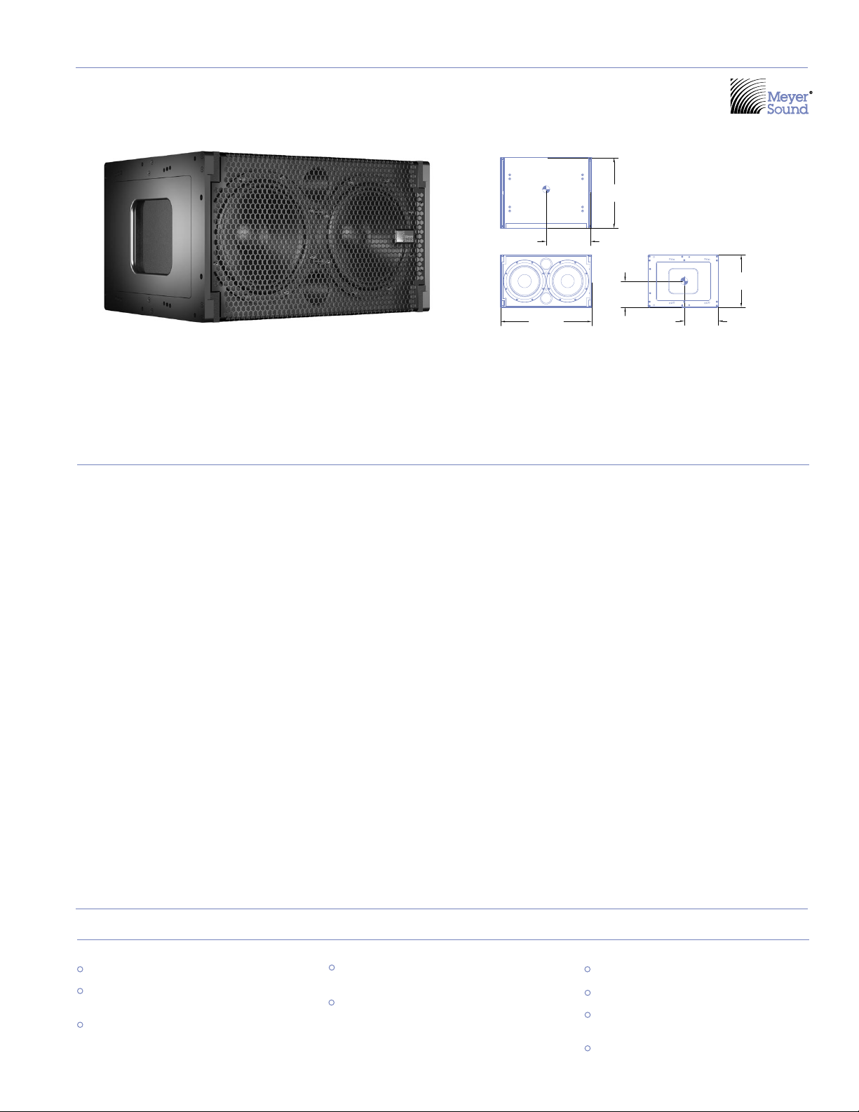
17.50
[445 mm]
22.62
[575 mm]
8.50
[216 mm]
6.50
[165 mm]
13.00
[330 mm]
11.06
[281 mm]
M1D™-SUB : Ultra-Compact Subwoofer
M SERIES
The M1D-Sub ultra-compact subwoofer
complements the M1D ultra-compact curvilinear array loudspeaker by extending
bandwidth with its operating frequency
range of 32 Hz to 180 Hz and substantially increasing overall system headroom.
Because it produces a prodigious peak SPL
of 130 dB at 1 meter from a compact cabinet, the M1D-Sub allows system designers
to minimize array size while maximizing
system response. A variety of QuickFly
rigging options allows the M1D-Sub to be
flown above, below or within an array, or
placed at the base of a ground-stacked
array. Although it is intended primarily as a
companion subwoofer to the M1D, it is perfectly suited to general use where powerful
low frequency augmentation is desired.
M1D-Sub contains two robust 10-inch
cone drivers, each featuring a 2-inch voice
coil and a lightweight neodymium magnet
structure. Power rating per driver is 400
AES watts (see note 5 on back page). A fully
Dimensions
Weight
Enclosure
Finish
Protective Grille
Rigging
integrated and self-powered system, the
M1D-Sub also incorporates a two-channel
class AB/bridged complementary MOSFET
amplifier with 450 watts total burst capability. An Intelligent AC power supply selects
the correct operating voltage in the range
of 90 to 264 V AC at 50 or 60 Hz, allowing
international use without manually setting
voltage switches. The Intelligent AC supply also performs protective functions to
compensate for hostile conditions on the
AC mains. These functions protect both the
loudspeaker and electronics from erratic
AC conditions and increase the lifespan of
the loudspeaker. An ultra-low-noise fan
is fitted, but cooling is primarily provided
by a massive external extruded aluminum
heat sink.
The vented M1D-Sub cabinet is constructed
of multi-ply hardwood with a durable finish
suited to touring or installed use. A metal
grille protects the drivers.
22.62" W x 13.00" H x 17.50" D
(575 mm x 330 mm x 445 mm)
70 lbs (31.75 kg); shipping: 75 lbs (34.02 kg)
Multi-ply hardwood
Black textured
Powder-coated hex stamped steel
QuickFly® MRF-1D-Sub rigging frame
M1D-Sub features Meyer Sound’s QuickFly
rigging system with rugged, reliable and
deceptively simple components. All load
stresses are transmitted through the rigging frames and associated hardware, not
through the wooden cabinets. The optional
QuickFly MG-1D multipurpose grid allows
either flying or ground stacking various
combinations of M1D and M1D-Sub. Up to
16 M1Ds (or the equivalent weight of M1D
and M1D-Sub) with a 7:1 safety factor may
be flown, or up to 8 M1Ds or 4 M1D-Subs
may be ground stacked. For flying only, the
simpler optional MTG-1D will support up to
16 M1Ds (or the equivalent weight of M1D
and M1D-Sub) with a 7:1 safety factor.
The M1D-Sub includes Meyer Sound’s RMS™
monitoring system as standard. RMS allows
the full range of operating parameters to
be monitored in real time, remotely over a
network using a Windows® computer.
features & benefits
Extremely compact and lightweight
High power-to-size ratio for maximum
installation flexibility
Exceptional fidelity and peak capability
assure clean, high-impact lows
QuickFly rigging system simplifies
use in flown or ground-stacked arrays
Seamless integration with M1D
loudspeakers
applications
Theatrical sound reinforcement
Houses of worship
Portable and installed audio-visual
systems
Surround playback systems
Page 2

M1D-Sub specifications
Made by Meyer Sound, Berkeley, CA, USA
European Office:
Meyer Sound Germany
GmbH
Carl Zeiss Strasse 13
56751 Polch, Germany
Acoustical
Coverage
Transducers
Audio In put
Amplifiers
AC Power
RMS Netw ork
1
Operating Frequency Range
Frequency Response
Phase Response
Maximum Peak SPL
Dynamic Range
Horizontal Coverage
Vertical Coverage
Low Frequency
Maximum Common Mode Range
Connectors
Input Impedance
DC Blocking
RF Filter
TIM Filter
Nominal Input Sensitivity
Input Level
Output Power
THD, IM, TIM
Load Capacity
Cooling
Connector
Automatic Voltage Selection
Safety Agency Rated Operating Range
Turn-on and Turn-off Points
Current Draw8:
Idle Current
Max Long-Term Continuous Current (>10 sec)
Burst Current (<1 sec)
Ultimate Short-Term Peak Current Draw
Inrush Current
Type
Wiring
CMRR
Type
2
32 H z - 18 0 Hz
3
35 Hz - 160 Hz ±4 dB
50 Hz - 120 Hz ±45°
4
130 dB
>110 dB
360°
Varies, depending on array length and configuration
Two 10" cone drivers with neodymium magnets
Nominal impedance: 4 Ω
Voice coil size: 2"
Power-handling capability: 400 W (AES)5
Differential, electronically balanced
±15 V DC, clamped to earth for voltage transient protection
Female XLR input with male XLR loop output
10 kΩ differential between pins 2 and 3
Pin 1: Chassis/earth through 220 kΩ, 1000 pF, 15 V clamp network to
provide virtual ground lift at audiofrequencies
Pin 2: Signal +
Pin 3: Signal -
Case: Earth ground and chassis
Differential DC blocking up to maximum common mode voltage
>50 dB, typically 80 dB (50 Hz - 500 Hz)
Common mode: 425 kHz
Differential mode: 142 kHz
Integral to signal processing (<80 kHz)
0 dB V (1 V rms, 1.4 V pk) continuous is typically the onset of limiting
for noise and music
Audio source must be capable of producing a minimum of +20 dB V (10
V rms, 14 V pk) into 600 Ω inorder to produce maximum peak SPL over
the operating bandwidth of the loudspeaker
Two-channel complementary MOSFET output stages (class AB/bridged)
6
450 W total
<.02 %
4 Ω each channel
Forced air cooling over amplifier heatsink
PowerCon with looping output
Automatic
100 - 240 V AC; 50/60 Hz
7
Continuous 90 - 264 V AC; 50/60 Hz
0.41 A rms (115 V AC); 0.33 A rms (230 V AC); 0.42 A rms (100 V AC)
3.2 A rms (115 V AC); 1.6 A rms (230 V AC); 3.7 A rms (100 V AC)
5.0 A rms (115 V AC); 2.5 A rms (230 V AC); 5.8 A rms (100 V AC)
17 A pk (115 V AC); 8.5 A pk (230 V AC); 20 A pk (100 V AC)
15 A pk (115 V AC); 13 A pk (230 V AC); 15 A pk (100 V AC)
Equipped for two conductor twisted-pair network, reporting all
operating parameters ofamplifiers to system operator’s host computer.
Notes:
1. The low-frequency power response
of the system will increase according
to the length of the array.
2. Recommended maximum operating
frequency range. Response depends
on loading conditions and room
acoustics.
3. Free field, measured with 1/3 octave
frequency resolution at 4 meters.
4. Measured with music at 1 meter.
5. Power handling is measured under
AES standard conditions: transducer
driven continuously for two hours
with band-limited noise signal
having a 6 dB peak-average ratio.
6. Amplifier wattage rating based on
the maximum unclipped burst sinewave rms voltage that the amplifier
will produce into the nominal load
impedance. Both channels: 30 V rms
(42 V pk).
7. No automatic turn-off voltages.
Voltages above 264 V AC are fuse
protected but may cause permanent
damage to the power supply.
Voltages below 90 V AC may result in
intermittent operation.
8. Current draw for a single
loudspeaker. Loop out not used.
M1D-S UB - 04 .116. 001. 01 C
meyer sound laboratories inc.
2832 San Pablo Avenue
Berkeley, CA 94702
T: +1 510 486.1166
F: +1 510 486.8356
techsupport@meyersound.com
www.meyersound.com
Copyright © 2006
Meyer Sound Laboratories Inc.
All rights reserved
architect specifications
The loudspeaker shall be a self-powered, sub-bass system
that may be deployed as part of a flown array or placed separately in proximity to the mid-high M1D array. The transducers
shall consist of two 10-inch cone drivers (2-inch voice coil)
each rated to handle 400 AES* watts.
The loudspeaker shall incorporate internal processing electronics and a two-channel amplifier. Each amplifier channel
shall be class AB/bridged with complementary MOSFET output
stages. Burst capability shall be 450 watts total with nominal
4-ohm resistive load on each channel. Distortion (THD, IM,
TIM) shall not exceed 0.02%. Protection circuits shall include
peak and rms limiting. The audio input shall be electronically
balanced with a 10 kOhm impedance and accept a nominal 0
dBu (1 V rms, 1.4 V pk) signal (+20 dBV to produce maximum
SPL). Connectors shall be XLR (A-3) type male and female. RF
filtering shall be provided, and CMRR shall be greater than 50
dB (80 dB 50 – 500 Hz).
Performance specifications for a typical production unit shall
be as follows, measured at 1/3 octave resolution: Operating
frequency range shall be 32 Hz to 180 Hz. Phase response shall
be ±45° from 35 Hz to 160 Hz. Maximum SPL shall be 130 dB
at 1 meter. Coverage shall be 360° horizontal. (Vertical varies
with array configuration.)
The internal power supply shall perform automatic voltage
selection, EMI filtering, soft current turn-on and surge suppression. Powering requirements shall be 90 to 264 V AC line
current at 50 Hz or 60 Hz. UL and CE operating voltage range
shall be 100 V AC to 240 V AC. Current draw during burst shall
be 5 A at 115 V AC and 2.5 A at 230 V AC. Inrush current during
turn-on shall not exceed 15 A at 115 V. AC power connectors
shall be locking PowerCon with loop output.
The loudspeaker system shall incorporate the electronics
module for Meyer Sound’s RMS remote monitoring and
control system.
All loudspeaker components s hall be mounted in an
enclosure constructed of multi-ply hardwood with a black
textured finish. The front protective grille shall be powder-coated, hex stamped steel. Dimensions shall be 22.62"
wide x 13" high x 17.50" deep (575 mm x 330 mm x 445 mm).
Weight shall be 70 lbs (31.75 kg).
The loudspeaker shall be the Meyer Sound Model M1DSub.
*Driven continuously for two hours with band-limited noise
signal having a 6 dB peak-average ratio.
 Loading...