

Meyer Sound LYON-M-RMS-RIG, LYON-WXT-RMS-RIG-WP, LYON-WXT-RMS-RIG, LYON-W-RMS-RIG-WP, LYON-W-RMS-RIG Quick Start Guide
...Page 1
OPERATING INSTRUCTIONS
Pull Back Rigging
Keep these important operating instructions. Check www.meyersound.com for updates.
Page 2

2018
©
Meyer Sound. All rights reserved.
Pull Back Rigging Operating Instructions, PN 05.083.008.01 Rev A
The contents of this manual are furnished for informational purposes only, are subject to change without notice, and should not be construed as a commitment by Meyer Sound Laboratories Inc. Meyer Sound assumes no responsibility or liability for any errors or inaccuracies that may appear in this manual. Except as permitted by applicable copyright law, no part of this publication may be reproduced,
stored in a retrieval system, or transmitted, in any form or by any means, electronic, mechanical, recording or otherwise, without prior
writ-ten permission from Meyer Sound.
Compass RMS, GuideALink, Intelligent AC, LEO-M, LYON, LINA, MAPP, QuietCool, RMS, RMServer, and all alpha-numeric designations
for Meyer Sound products and accessories are trademarks of Meyer Sound. Callisto, Galileo, LEO, Meyer Sound, the Meyer Sound wave
logo, MICA, QuickFly, REM, SIM, and TruPower are registered trademarks of Meyer Sound Laboratories Inc. (Reg. U.S. Pat. & Tm. Off.). All
third-party trademarks mentioned herein are the property of their respective trademark holders.
ii
Page 3
CHAPTER 1: INTRODUCTION
!
HOW TO USE THIS ASSEMBLY GUIDE
Make sure to read this assembly guide in its entirety before
configuring a loudspeaker system using pull-back.
In particular, pay close attention to material related to safety
issues. As you read this assembly guide, you will encounter
the following icons for notes, tips, and cautions:
As you read these instructions, you will encounter the following icons for notes, tips, and cautions:
NOTE: A note identifies an important or useful
piece of information relating to the topic under
discussion.
TIP: A tip offers a helpful tip relevant to the topic
at hand.
CAUTION: A caution gives notice that an
action may have serious consequences and
could cause harm to equipment or personnel, or
could cause delays or other problems.
Information and specifications are subject to change.
Updates and supplementary information are available at
www.meyersound.com
.
FACTOR OF SAFETY DISCLAIMER
Important: Read Carefully
Rated load capacities of the Meyer Sound rigging assembly
for different splay angle settings are based on testing performed by an independent testing agency, and on 5 to 1
safety limit analysis to ultimate load performed by an independent structural engineering firm. The ratings apply to the
Meyer Sound rigging only. You are responsible for the safety
factor required by local law for your installation, and for
determining the adequacy of supporting structure "above
the hook." PERMANENT INSTALLATIONS MUST BE CERTIFIED BY THE ENGINEER OF RECORD FOR WIND AND
SEISMIC LOADING.
MAPP assumes the top grid is picked up by a front and rear
motor along the perimeter of the grid, either directly to the
middle pickup points or bridled at 45 degrees or greater to
the grid's outermost pickup points. Other rigging configurations may have reduced load capacity. These cases should
be reviewed by proper personnel to verify load capacities for
alternate configurations.
Bridle angles are measured between the bridle cable and
top grid plane.
Meyer Sound Technical Support is available at:
■ Tel: +1 510 486.1166
■ Tel: +1 510 486.0657 (after hours support)
■ Web: www.meyersound.com/support
■ Email: techsupport@meyersound.com
Center Bar Pickup Points
MAPP Factor of Safety calculations are made for peripheral
top grid points -- either corner or middle -- depending on
the top grid configuration. Using the center bar pickup
points will result in reduced load capacity. These cases
should be reviewed by proper personnel to validate the configuration.
Pull-Back Load Status
MAPP Load Status -- when using Pull-Back -- additionally
takes into account the Pull-Back Load Status as an additional pass/fail criteria to determine the overall Load Status
condition. The Vertical Pull-Back Load Status is the pass/fail
criteria. The -10º/+10º status indicators provide the user of
the tolerance that exists to each side of the vertical. For all
purposes Pull-Back should be as close to vertical as possible as loads will vary. Deviations from a vertical Pull-Back
should be reviewed by proper personnel to verify load
capacities for alternate configurations.
3
Page 4

CHAPTER 1: INTRODUCTION
Rig Point Spacing
When using Pull-Back, Rig Point Spacing values are calculated with reference to the front of grid position, which is the
Reference Point Position value for the array at its final resting configuration.
LIMITATIONS AND DISCLAIMER
The safety limit analysis provided by this program does not
apply, and may not be relied upon, if your loudspeaker system (1) has been improperly installed or maintained, (2) the
rigging or loudspeakers of your system have been damaged
prior to installation, (3) your indicated configuration of the
system has been altered, (4) any weight has been added to
your indicated configuration, or (5) your system is in an outdoor venue and remains installed during strong wind conditions. MEYER SOUND ASSUMES NO RESPONSIBILITY
FOR ANY PART OF AN INSTALLATION "ABOVE THE
HOOK" OR WHERE ANY OF THE FOREGOING LIMITATIONS APPLY.
4
Page 5

CHAPTER 2: PULL BACK RIGGING INSTRUCTIONS
Executing a pull back requires balancing the loads of suspended arrays. By altering the momentary load on each motor to
achieve a new stable configuration, this dynamically shifts the array’s center of gravity. These procedures ensure a safe tran-
sition from top grid suspension to full pull back.
NOMENCLATURE
The following figures define the rigging points used in these instructions.
Top Front and Rear of Array Center Rigging Points (left); Top Front and Rear of Array Bridled Rigging Points (right)
Rear View of Bridled Pull-Back Points
3
Page 6

PULL BACK RIGGING OPERATING INSTRUCTIONS
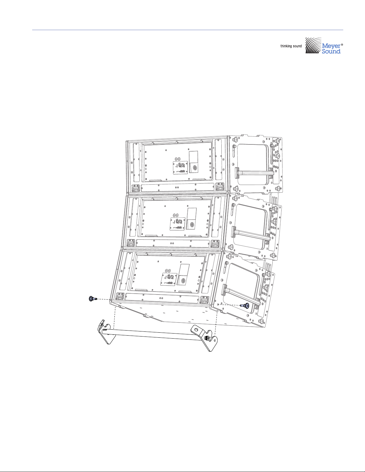
TOP GRID TO PULL BACK RIGGING ARRANGEMENT
Assemble the Array
Before you can achieve a pull back rigging configuration, the full array must first be set up as a regular top grid rigging system.
1. Maneuver the top grid motors to assemble the full array with the intended splay angles.
2. Fasten any locking pins in place when appropriate.
NOTE: Refer to each product’s rigging manual/operating instructions for specific rigging instructions and pro-
cedures.
Get the System Off the Ground
When the array is fully assembled including the pull back bar:
3. Raise the array slightly above the ground.
4. Inspect all links, pins, and rigging accessories.
5. Raise the array to trim height (resting height of array).
During the transition, only the top rear of array rigging points will remain at a constant height. It is therefore essential to
measure and set the trim height for these reference points.
TRANSITIONING
Transitioning can be divided into movement and load procedures. The symbols used are shown below.
Symbols used for movement and load procedures
4
Page 7

Movement
Step 1 Step 2 Step 3 Step 4 Step 5
Movement to transition from top grid to pull back
To transition from top grid to pull back:
PULL BACK RIGGING OPERATING INSTRUCTIONS
1. Use the top grid motors to raise the array to trim height.
2. Slack the front motor until achieving the maximum natural downward tilt.
Make sure there is enough slack in the top front of array motor(s) to allow the added rotation introduced by the pull back.
3. Pick up the slack of the pull back motor until it is under tension.
4. Without exceeding the rated pull back load, take the pull back motor up to the desired downward tilt angle.
NOTE: Make sure the downward tilt angle does not exceed the simulated configuration in MAPP XT. This may
result in an unstable array or exceed the maximum rated pull back load.
5. Pick up the slack of the top front of array motor points.
Do not use the top front of array motors to pick up the top grid, change the trim height, or change the angle as that will
alter the MAPP XT calculated loads.
NOTE: Removing the slack is only to ensure that any failure of the top rear of array motor will result in the load
being picked up by the top front of array motor points.
5
Page 8

PULL BACK RIGGING OPERATING INSTRUCTIONS
Step 1 Step 2 Step 3 Step 4 Step 5
Load
Load transition
1. Engage both top grid motors to take the complete load of the array.
2. When at trim height (top rear of array motor point reference), the load is fully transitioned to the top rear of array motor
point(s).
3. Total array load is distributed between the top rear of array motor point(s) and the pull back rigging point.
4. The pull back rigging motor point load increases until it reaches the desired array downward tilt angle.
5. The top front of array motor point(s) should be tensioned with minimal load to avoid rattling and provide an extra safety
rigging point.
NOTE: Changing the top of array pickup point from the rear to the front increases the pull back rigging motor point
load and reduces array stability.
6
Page 9

TRANSITIONING FROM PULL BACK TO TOP GRID RIGGING
Step 1 Step 2 Step 3 Step 4 Step 5
!
!
Movement
Pull back to top grid rigging
PULL BACK RIGGING OPERATING INSTRUCTIONS
To transition from a pull back to standard top grid rigging configuration:
1. The is array is resting at the pull back position.
2. From the pull back position, slack the pull back motor until the array is hanging only from the top rear of array motor points.
Make sure there is enough slack in the pull back motor so this motor will never be under tension.
3. Pick up the slack of the top front of array motor points until the weight is distributed by all top grid motor points.
4. Lower all top grid and pull back motors at the same time.
Make sure there is enough slack in the pull back motor so it will never be under tension.
If necessary stop the downward motion on all motors and increase the slack of the pull back motor.
5. When the array is close to the ground, disconnect the pull back and disassemble the array.
CAUTION: To minimize potentially dangerous situations and prevent accidents, you must maintain all rigging
gear and follow all safety procedures and local regulations. Replace worn or damaged parts and accessories
immediately.
CAUTION: Factor of Safety Intermediate Data calculations provided by the MAPP XT program for Meyer Sound
rigging configurations depend on the proper installation, maintenance, and use of the rigging. Read all rigging
instructions provided by Meyer Sound. Failure to follow these Operating Instructions, or failure to inspect, maintain, and
repair all rigging parts and accessories will void Factor of Safety calculations.
NOTE: Local rigging regulations may require dead hanging all loads or providing safety links that bypass all
motors. A dead hang uses a steel wire or chain to remove all load from the motor unit used to take the load to
its dead hung position.
7
Page 10

Meyer Sound Laboratories Inc.
2832 San Pablo Avenue
Berkeley, CA 94702
+1 510 486.1166
www.meyersound.com
© 2018
Meyer Sound. All rights reserved.
Pull Back RiggingOperating Instructions
PN 05.083.008.01 RevA
 Loading...