

Page 1
ASSEMBLY GUIDE
MG-LEOPARD/900 Multipurpose Grid and Accessories
LINE ARRAY
Keep these important operating instructions.
Check www.meyersound.com for updates.
Page 2

© 2015
Meyer Sound. All rights reserved.
MG-LEOPARD/900 Multipurpose Grid and Accessories Assembly Guide, PN 05.243.080.01 A
The contents of this manual are furnished for informational purposes only, are subject to change without notice, and should not be construed as a commitment by Meyer Sound Laboratories Inc. Meyer Sound assumes no responsibility or liability for any errors or inaccuracies that may appear in this manual. Except as permitted by applicable copyright law, no part of this publication may be reproduced,
stored in a retrieval system, or transmitted, in any form or by any means, electronic, mechanical, recording or otherwise, without prior written permission from Meyer Sound.
Compass RMS, GuideALink, LEO-M, LEOPARD, LYON, MAPP, RMS, RMServer, and all alpha-numeric designations for Meyer Sound
products and accessories are trademarks of Meyer Sound. Callisto, Galileo, LEO, Meyer Sound, the Meyer Sound wave logo, MICA,
QuickFly, SIM, and Thinking Sound are registered trademarks of Meyer Sound Laboratories Inc. (Reg. U.S. Pat. & Tm. Off.). All third-party
trademarks mentioned herein are the property of their respective trademark holders.
ii
Page 3

CONTENTS
Chapter 1: Introduction 5
How to Use This Manual 5
Safety Statement for QuickFly Rigging 5
LEOPARD and 900-LFC Rigging Options 7
Chapter 2: 900-LFC Groundstacks and Cardioid Arrays 11
Groundstacking 900-LFC Loudspeakers (Without Grid) 11
900-LFC Cardioid Arrays 12
Chapter 3: MRK-900 Rigging Upgrade Kit 15
MRK-900 Rigging Upgrade Kit Contents 15
Installing the MRK-900 Rigging Upgrade Kit 16
Chapter 4: Loudspeaker GuideALinks 19
LEOPARD GuideALinks 19
900-LFC GuideALinks 23
Chapter 5: MG-LEOPARD/900 Multipurpose Grid 27
MG-LEOPARD/900 Grid Kit Contents 28
MG-LEOPARD/900 Grid Dimensions 29
MG-LEOPARD/900 Grid Load Ratings 30
Additional Requirements for MG-LEOPARD/900 Grid Load Ratings 32
Chapter 6: Flying Arrays 33
Grid Orientation for Flown Arrays 33
Attaching Flown Arrays to the MG-LEOPARD/900 34
MG-LEOPARD/900 Pickup Configurations 35
Using MAPP to Calculate Single Pickup Points 41
Chapter 7: MVP Motor Vee Plate 43
MVP Motor Vee Plate Kit Contents 44
MVP Motor Vee Plate Load Ratings 44
Chapter 8: MTF-LYON/LEOPARD Transition Frame 45
MTF-LYON/LEOPARD Transition Frame Kit Contents 46
MTF-LYON/LEOPARD Transition Frame Dimensions 46
Collapsing the MTF-LYON/LEOPARD Transition Frame 47
MTF-LYON/LEOPARD Transition Frame Load Ratings (Loudspeaker) 48
MTF-LYON/LEOPARD Transition Frame Load Ratings (Pull-Back) 49
Using the MTF-LYON/LEOPARD Transition Frame for Pull-Back and Pull-Up 49
Chapter 9: PBF-LEOPARD Pull-Back Frame 51
PBF-LEOPARD Kit Contents 52
PBF-LEOPARD Transition Frame Dimensions 52
PBF-LEOPARD Transition Frame Load Ratings 52
Verifying Pull-Back Requirements in MAPP 53
iii
Page 4

Chapter 10: Groundstacking with the MG-LEOPARD/900 Grid 55
Configuring GuideALinks for the MG-LEOPARD/900 Grid 57
Grid Orientation and Groundstacks 58
Adding Groundstack Tilt with the Angle Feet 59
Groundstacking LEOPARDs on the 900-LFC 60
Chapter 11: MCF-LEOPARD Caster Frame 65
MCF-LEOPARD Caster Frame Dimensions 67
MCF-LEOPARD Truck Packing Examples 68
Safety Guidelines for the MCF-LEOPARD Caster Frame 69
Chapter 12: MCF-900 Caster Frame 71
MCF-900 Caster Frame Dimensions 74
MCF-900 Truck Packing Examples 75
Reconfiguring the MCF-900 Caster Frame 76
Safety Guidelines for the MCF-900 Caster Frame 77
Appendix A: Assembling Arrays with the MG-LEOPARD/900 Grid 79
Appendix B: Laser Bracket 83
iv
Page 5
CHAPTER 1: INTRODUCTION
!
HOW TO USE THIS MANUAL
Make sure to read these instructions in their entirety before configuring a Meyer Sound loudspeaker system. In particular,
pay close attention to material related to safety issues.
As you read these instructions, you will encounter the following icons for notes, tips, and cautions:
NOTE: A note identifies an important or useful piece of information relating to the topic under discussion.
TIP: A tip offers a helpful tip relevant to the topic at hand.
CAUTION: A caution gives notice that an action may have serious consequences and could cause harm to
equipment or personnel, or could cause delays or other problems.
Information and specifications are subject to change. Updates and supplementary information are available at
www.meyersound.com
Meyer Sound Technical Support is available at:
■ Te l: +1 510 486.1166
■ Te l: +1 510 486.0657 (after hours support)
■ Web: www.meyersound.com/support
.
■ Email: techsupport@meyersound.com
SAFETY STATEMENT FOR QUICKFLY RIGGING
Please read this Statement carefully and in its entirety. It contains important information regarding safety issues, including
guidelines for general safe use of rigging systems as well as advisories on government regulations and liability laws.
This Statement assumes that the owners and/or users of a QuickFly
®
system are knowledgeable and experienced in the areas
of rigging and flying loudspeaker systems. Many issues of crucial concern, such as the determination of appropriateness and
condition of venue rigging points, cannot be addressed here. Therefore, the user must assume all responsibility for the appropriate use of QuickFly systems in any particular location or circumstance.
The suspension of large, heavy objects in public places is subject to numerous laws and regulations at the national/federal,
state/provincial, and local levels. The user must assume responsibility for making sure that use of any QuickFly system and
its components in any particular circumstance or venue conforms to all applicable laws and regulations in force at the time.
Load Ratings and Specifications
Long-term safe operation is a central concern in the design and manufacture of any rigging/flying system. Meyer Sound has
taken great care in material selection and component design. In all critical cases, load points are redundant, with a safety margin that allows one or more load points to fail while maintaining system integrity. After manufacture, all load-critical system
components are individually inspected.
All load ratings and other specifications given in this manual are the result of accepted engineering practice and careful testing. However, such specifications and ratings are subject to change. Users are advised to check the QuickFly section of the
Meyer Sound website at
www.meyersound.com
or contact Technical Support at regular intervals to check for updated or revised information.
5
Page 6

CHAPTER 1: INTRODUCTION
Regulatory Compliance
The design and safe working load (SWL) ratings of the QuickFly system are intended to be in compliance with all known regulatory statutes currently applicable in the United States. Unless otherwise specified, all working loads are based on a 7:1
safety factor. However, as noted above, there are wide variations internationally in the regulations and practices applying to
suspension of sound systems in public places. Although regulations in the United States are generally among the most
stringent, safety codes may be even stricter in a few localities (such as those highly prone to earthquakes). In addition, applicable safety codes are open to interpretation: Government officials in one location may have a stricter interpretation than
another local official, even when operating under the same regulations and in the same legal jurisdiction.
Consequently, users of QuickFly rigging systems should be prepared to take additional safety assurance measures beyond
those outlined in this Statement. IN ALL CASES, IT IS THE RESPONSIBILITY OF THE USER TO MAKE CERTAIN THAT ANY
MEYER SOUND LOUDSPEAKER SYSTEM IS SUSPENDED IN ACCORDANCE WITH ALL APPLICABLE NATIONAL/FEDERAL, STATE/PROVINCIAL, AND LOCAL REGULATIONS.
Safety Responsibilities “Above the Hook”
In most touring applications of rigging systems, the touring sound provider is normally responsible for ensuring the safety of
the suspension system only below the attachment point. The safety and suitability of the attachment point is generally seen
as the responsibility of the venue owner or operator. However, this distinction (“above the hook” versus “below the hook”)
can be open to interpretation. Touring system operators should double-check to make certain that attachment points are
approved and suitably load rated, and that the points used are those identified as such by the venue owner or operator. As
an extra precaution, careful inspection of the attachment points is advised before flying, particularly in older venues or those
hosting frequent events using large sound and lighting systems. IN ANY CASE, MEYER SOUND QUICKFLY SYSTEMS ARE
INTENDED ONLY FOR SUSPENSION FROM APPROVED RIGGING POINTS, EACH KNOWN TO HAVE AMPLE SWL MARGINS FOR THE SYSTEM COMPONENTS SUSPENDED BELOW THEM.
Inspection and Maintenance
The Meyer Sound QuickFly systems are an assembly of mechanical devices, and are therefore subject to wear and tear over
prolonged use, as well as damage from corrosive agents, extreme impact, or inappropriate use.
BECAUSE OF THE SAFETY ISSUES INVOLVED, USERS MUST ADOPT AND ADHERE TO A SCHEDULE OF REGULAR
INSPECTION AND MAINTENANCE. IN TOURING APPLICATIONS, KEY COMPONENTS MUST BE INSPECTED BEFORE
EACH USE. Such inspection includes examination of all load-bearing components for any sign of undue wear, twisting, buckling, cracking, rusting, or other corrosion. In regard to rust and corrosion, the main components of a QuickFly system are either
protected by an exterior coating or made from stainless steel, which is impervious to rust and resistant to most corrosive fluids. Nevertheless, normal use and shipping vibrations can wear through the protective coatings, and extremely corrosive fluids
(such as battery acid) can cause severe damage with prolonged exposure even to protected parts. Particular attention should
be given to screws, bolts, and other fasteners to make certain the fittings are tight and secure. Metal seams and welds should
be examined for any sign of separation or deformation. Meyer Sound strongly recommends that written documentation be
maintained on each QuickFly system, noting date of inspection, name of inspector, points of system checked, and any anomalies discovered.
Annual Comprehensive Examination and Test Program
In addition to routine checks on the road for touring systems, Meyer Sound also recommends a careful, comprehensive system examination and testing “at home” in the warehouse or other appropriate location at regular intervals. Such at home
examinations and tests should occur at least once a year, and should include a careful inspection of each component under
ideal lighting conditions, and then a final comprehensive check of the entire system after it has been flown.
If any anomalies or defects are discovered that could possibly affect the safety or integrity of the system, affected parts or subsystems should be replaced in their entirety before that part of the system is flown again.
6
Page 7

MG-LEOPARD/900 GRID ASSEMBLY GUIDE
Replacement Parts
Any component found to be defective, or any safety-related component you even suspect might be defective, should be
replaced with the equivalent, approved part. Parts specific to a QuickFly system should be ordered directly from Meyer
Sound. No attempt should be made to substitute what appears to be equivalent or “mostly the same” generic replacements.
Some parts used in QuickFly systems are identical to those used in other rigging applications. To the best of our knowledge,
most of these suppliers are reputable and their products are reliable. However, Meyer Sound has no way of assuring the
quality of products made by these various suppliers. Therefore, Meyer Sound is not responsible for problems caused by
components that were not supplied by Meyer Sound.
Training
QuickFly systems are relatively straightforward and easy to use. However, they should only be used by persons trained in
the use of loudspeaker rigging systems, who have mastered key points of assembly, rigging and flying.
LEOPARD AND 900-LFC RIGGING OPTIONS
This assembly guide documents the following rigging options:
■ MRK-900 rigging upgrade kit (PN 40.246.168.01)
■ MG-LEOPARD/900 multipurpose grid (PN 40.243.080.01)
■ MVP motor Vee plate (PN 40.215.184.01)
■ MTF-LYON/LEOPARD transition frame (PN 40.232.140.01)
■ PBF-LEOPARD pull-back frame (PN 40.243.185.01)
■ MCF-LEOPARD caster frame (PN 40.243.130.01)
■ MCF-900 caster frame (PN 40.246.130.01)
7
Page 8

CHAPTER 1: INTRODUCTION
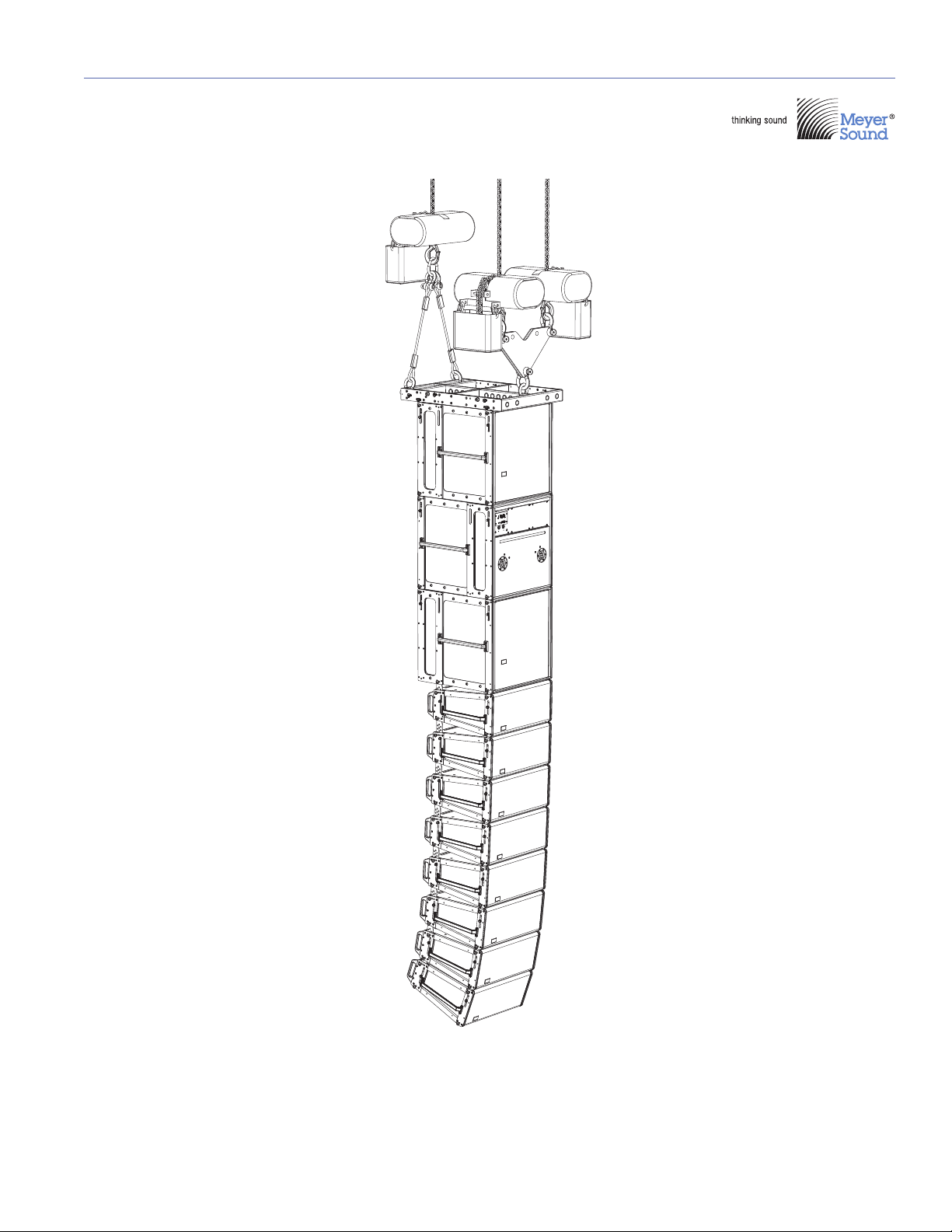
MG-LEOPARD/900
Multipurpose Grid
Oriented for maximum
array downtilt with four
pick-up points and two
motors
(12) LEOPARDs
Primary array
coverage
PBF-LEOPARD
Pull-Back Frame
Attached to bottom
cabinet to provide
pull-back for extreme
array downtilt
Rigging Example, LEOPARD Array with Pull-Back
8
Page 9
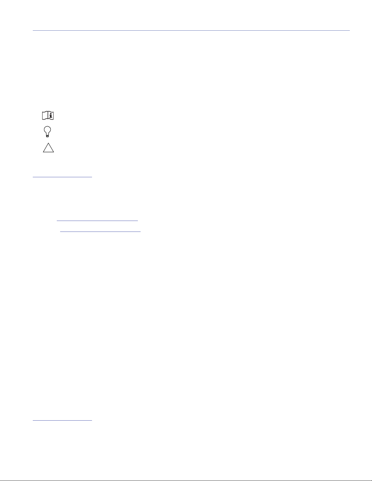
Rigging Example, Mixed Array with 900-LFCs and LEOPARDs
MG-LEOPARD/900
Multipurpose Grid
Oriented for maximum
array downtilt with three
pick-up points and
three motors
MVP Motor Vee Plate
Attached to front center
of grid with two motors
to adjust the horizontal
aim of the array
(2) 900-LFCs
Low-frequency
enhancement
(6) LEOPARDs
Primary array
coverage
MG-LEOPARD/900 GRID ASSEMBLY GUIDE
9
Page 10
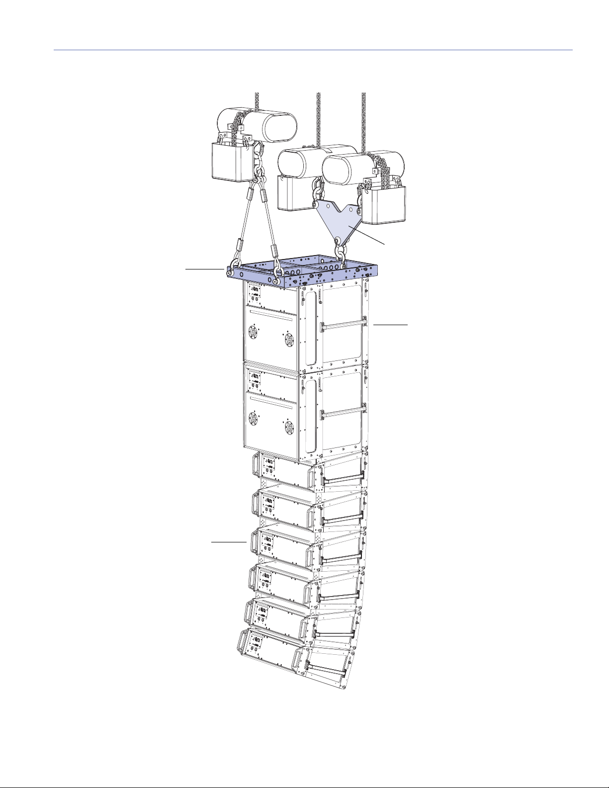
CHAPTER 1: INTRODUCTION
MVP Motor Vee Plate
Attached to front center
of grid with two motors
to adjust the horizontal
aim of the array
MTG-LYON Top Grid
Oriented for maximum
array downtilt with three
pick-up points
(12) LYON-Ms
Primary array
coverage
(4) LEOPARDs
Downfill coverage
MTF-LYON/LEOPARD
Transition Frame
Transitions from last LYON to
first LEOPARD (for downfill);
includes two rear attachment
points for array pull-back
Rigging Example, LYON Array with LEOPARD Downfill
10
Page 11
CHAPTER 2: 900-LFC GROUNDSTACKS AND CARDIOID ARRAYS
!
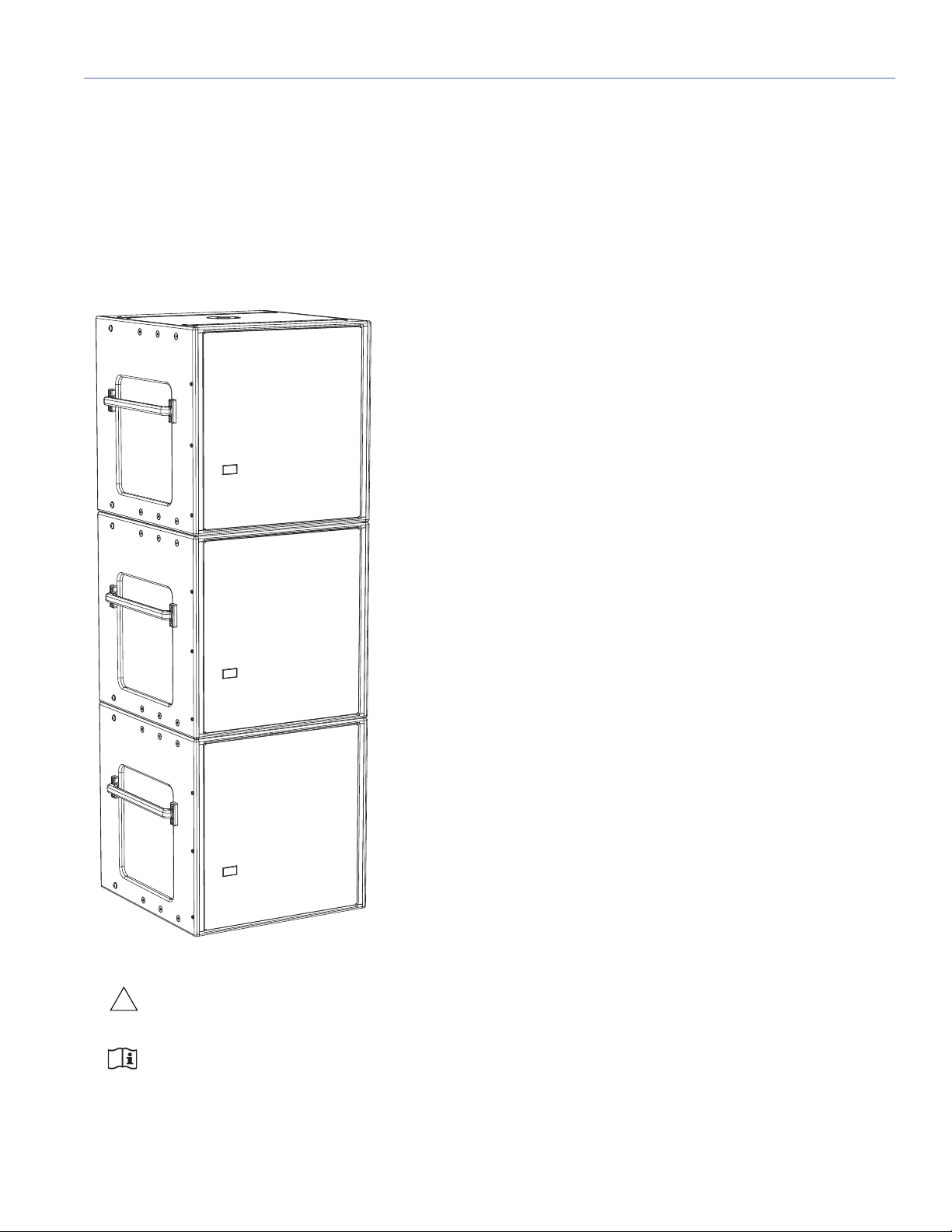
GROUNDSTACKING 900-LFC LOUDSPEAKERS (WITHOUT GRID)
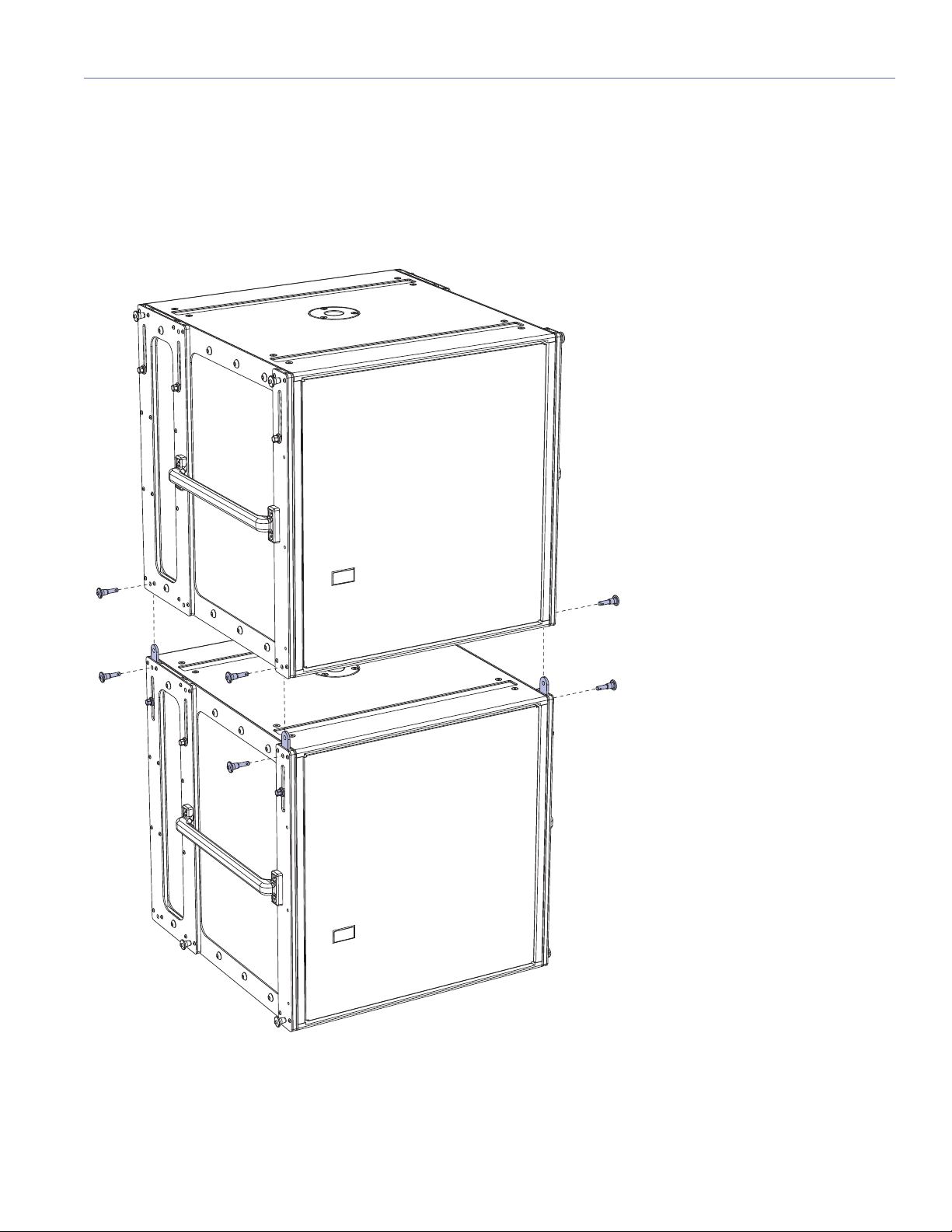
900-LFCs can be groundstacked up to three units high, with or without the MRK-900 rigging kit. Protective plastic skids are
included on the bottom of the 900-LFC cabinet that align with the slots on the cabinet top. Units can be stacked normally or
reversed for cardioid configurations. When groundstacking 900-LFCs, make sure the skids for each unit align with the slots
in the cabinet tops. When equipped with the MRK-900 rigging kit, the 900-LFC can be groundstacked on the MG-LEOPARD/
900 grid with LEOPARDs for mixed groundstacks (see Chapter 10, “Groundstacking with the MG-LEOPARD/900 Grid”).
900-LFC Groundstack (Without Rigging)
CAUTION: As a safety precaution, to avoid tipping, a maximum of three cabinets is supported for ground-
stacked 900-LFCs.
NOTE: 900-LFCs need not be equipped with the MRK-900 rigging kit for secure groundstacking of up to three
cabinets.
11
Page 12
CHAPTER 2: 900-LFC GROUNDSTACKS AND CARDIOID ARRAYS
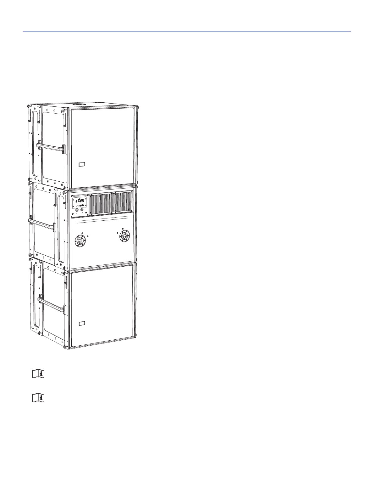
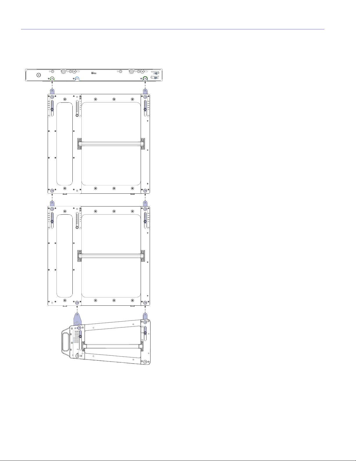
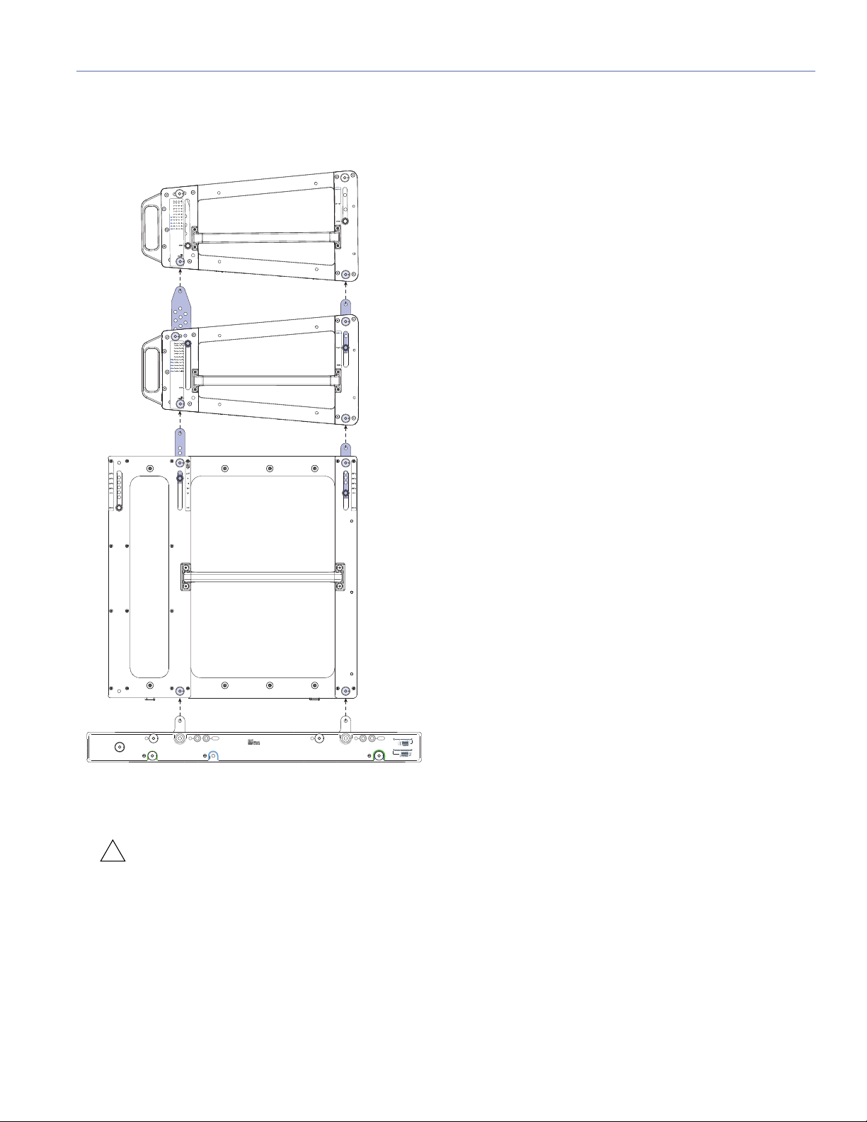
900-LFC CARDIOID ARRAYS
The 900-LFC can be configured in cardioid arrays to reduce output heard behind the loudspeakers. The loudspeaker’s linearity
ensures that cardioid patterns behave accurately even at very high levels. Cardioid arrays are achieved by placing three units
coplanar to each other (in either a groundstacked or flown array) with one unit facing the opposite direction. Polarity and delay
processing is applied to the rear-facing unit, which yields output that cancels output from the other loudspeakers normally present behind the units.
900-LFC Cardioid Groundstack (With Rigging)
NOTE: 900-LFCs need not be equipped with the MRK-900 rigging kit for groundstacked cardioid configura-
tions of up to three cabinets.
NOTE: 900-LFC cardioid arrays can also be flown from the MG-LEOPARD/900 multipurpose grid. For more infor-
mation, see Chapter 5, “MG-LEOPARD/900 Multipurpose Grid.”
12
Page 13

MG-LEOPARD/900 GRID ASSEMBLY GUIDE
NOTE: To achieve an accurate cardioid pattern, Meyer Sound’s MAPP prediction software and the Galileo®
Callisto 616 array processor are required. Use MAPP to calculate the appropriate ratio of forward to rear-facing
loudspeakers, as well as the Callisto 616 settings for polarity and delay. A myriad of cardioid and directional configurations are possible and can be calculated and predicted with MAPP. For more information, contact Meyer Sound
Technical Support.
13
Page 14

CHAPTER 2: 900-LFC GROUNDSTACKS AND CARDIOID ARRAYS
14
Page 15
CHAPTER 3: MRK-900 RIGGING UPGRADE KIT
The optional MRK-900 rigging upgrade kit allows the 900-LFC to be flown from the MG-LEOPARD/900 grid. The rigging kit
is available as a factory-installed option or as a field upgrade and uses rugged GuideALinks and intuitive quick-release pins
to securely link adjacent loudspeakers in flown and groundstacked array configurations.
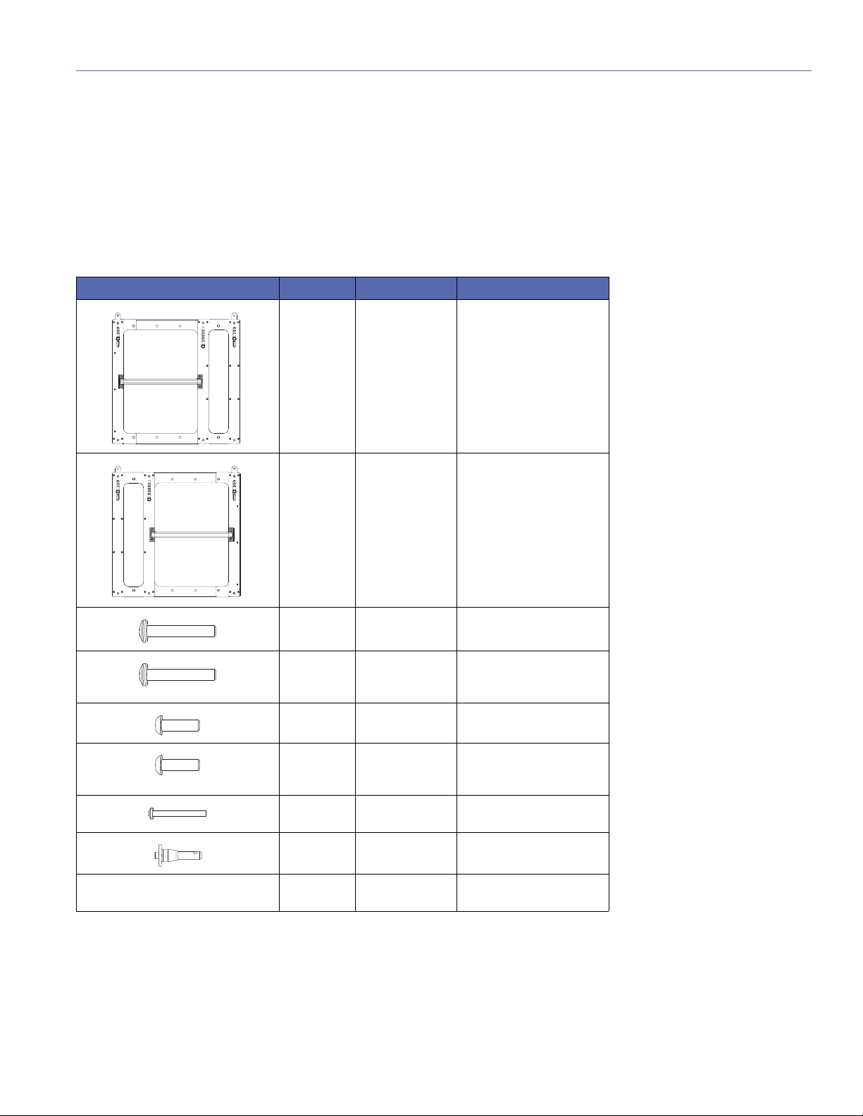
MRK-900 RIGGING UPGRADE KIT CONTENTS
MRK-900 Rigging Upgrade Kit, PN 40.246.168.01
Quantity Part Number Item
1 45.246.083.01 MRK-900 rigging endframe
with handle (right)
1 45.246.082.01 MRK-900 rigging endframe
with handle (left)
8 101.719 3/8-16 x 2.25-inch pan-
head socket bolts (black)
8 101.219 3/8-16 x 2.25-inch pan-
head socket bolts (silver,
weather protected)
8 101.695 3/8-16 x 1.25-inch pan-
head socket bolts (black)
8 101.195 3/8-16 x 1.25-inch pan-
head socket bolts (silver,
weather protected)
6 101.689 10-32 x 1.75-inch panhead
screws
8 134.024 5/16 x 0.63-inch quick-
release pins (black button)
1 640.096 Loctite Medium Strength
Threadlocker
15
Page 16
CHAPTER 3: MRK-900 RIGGING UPGRADE KIT
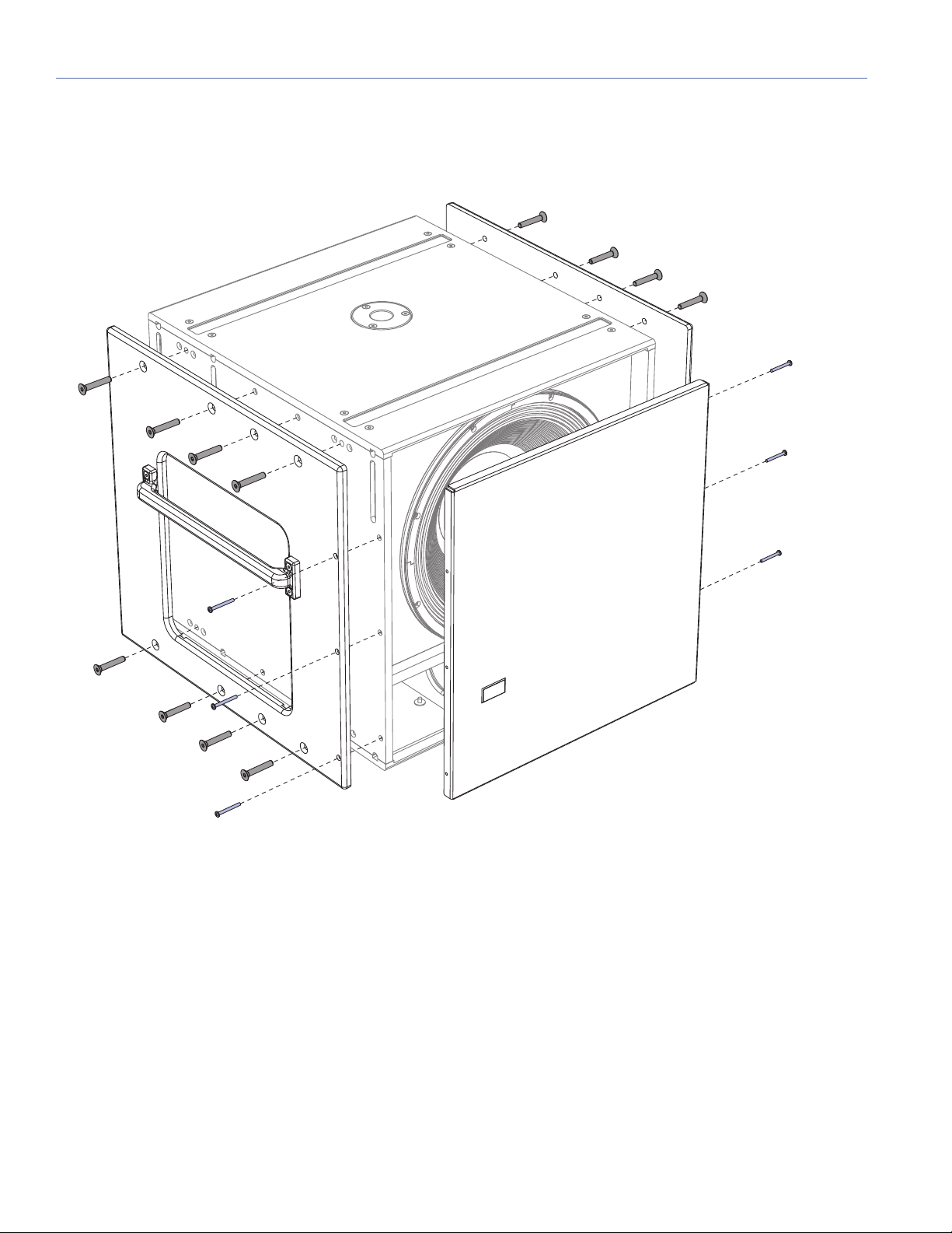
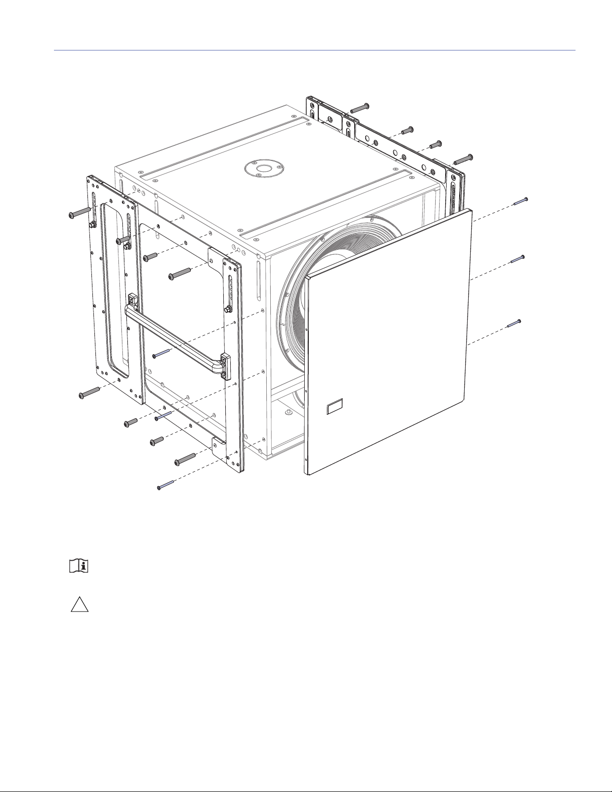
INSTALLING THE MRK-900 RIGGING UPGRADE KIT
To install the MRK-900 rigging upgrade kit:
1. Remove the standard endframes and temporarily remove the grille frame:
■ Use a Phillips screwdriver to remove the six 10-32 x 2.5-inch panhead screws (three each side) securing the grille frame
to the cabinet front. Remove the grille frame.
■ Use a 7/32-inch hex wrench to remove the (16) 3/8-16 x 2.25-inch flathead socket bolts (eight each side) from the cabi-
net sides. Remove the cabinet sides.
■ Set the removed fasteners aside. They will not be used for the MRK-900 endframes.
16
Page 17
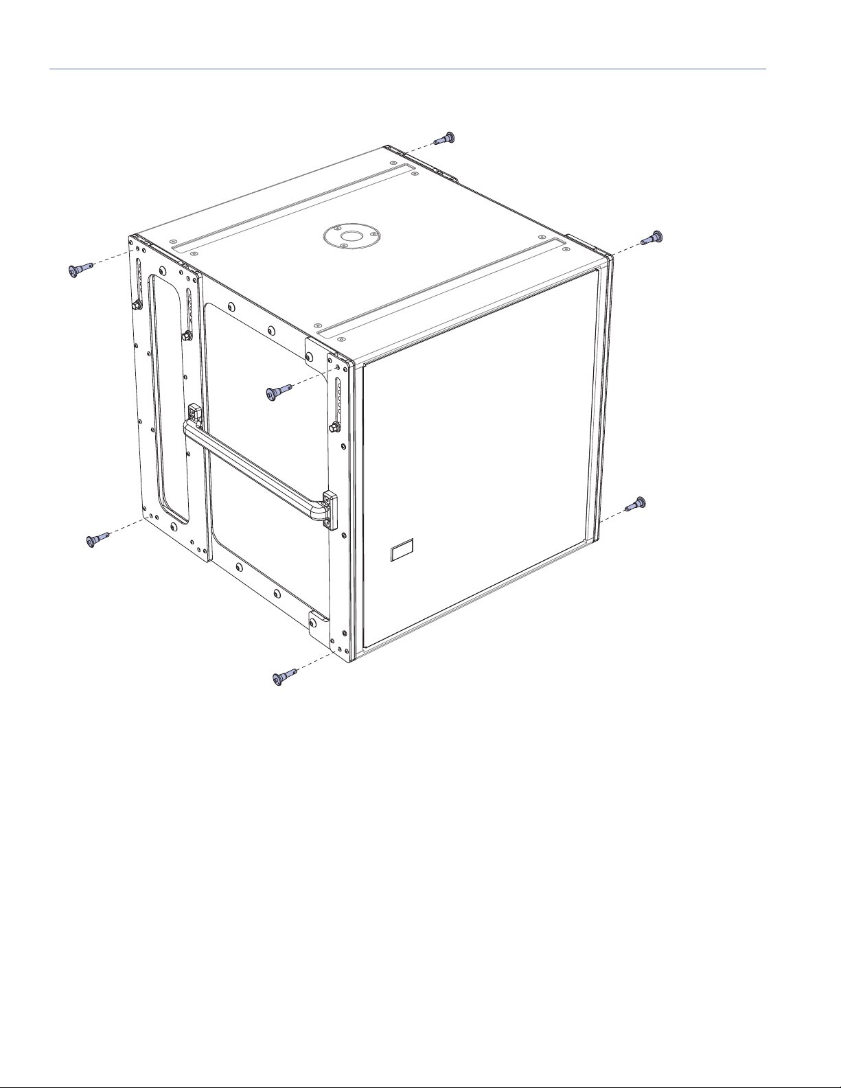
2. Attach the MRK-900 endframes and the previously removed grille frame:
!
MG-LEOPARD/900 GRID ASSEMBLY GUIDE
■ Use a 7/32-inch hex wrench to secure the MRK-900 end frames to the cabinet with the eight outer 3/8-16 x 2.25-inch
panhead socket bolts (PN 101.719) (four each side) and eight inner 3/8-16 x 1.25-inch panhead socket bolts (101.695)
(four each side). Apply one or two drops of Loctite to each of the socket bolts before installing them.
NOTE: For all-weather, outdoor installations, use the silver weather-protected panhead socket bolts
(PN 101.219 and PN 101.195).
CAUTION: Make sure the socket bolts are securely tightened but do not over-tighten them. Approximately
15 foot-pounds of torque is recommended.
■ Use a Phillips screwdriver to secure the grille frame to the cabinet with the six 10-32 x 1.75-inch panhead screws (three
each side). Apply one or two drops of Loctite to each of the panhead screws before installing them.
17
Page 18
CHAPTER 3: MRK-900 RIGGING UPGRADE KIT
3. Insert the eight 5/16 x 0.63-inch quick-release pins in the cabinet corners (four each side).
18
Page 19
CHAPTER 4: LOUDSPEAKER GUIDEALINKS
!
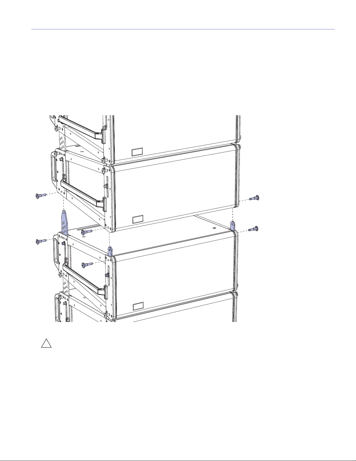
LEOPARD GUIDEALINKS
LEOPARD is equipped with four captive GuideALinks that link to adjacent LEOPARDs or 900-LFCs in flown and groundstacked arrays. Located at the top corners of the cabinet, GuideALinks extend up and into the link slots of the cabinet
above it, or into the link slots of the MG-LEOPARD/900 grid or MTF-LYON/LEOPARD transition frame. GuideALinks extend
and retract with knobs and are secured with two quick-release pins: one each in the top and bottom cabinets. Each
LEOPARD loudspeaker ships with eight 5/16 x 0.063-inch quick-release pins (black button) (PN 134.024).
LEOPARD GuideALinks with Quick-Release Pins, Exploded View
CAUTION: GuideALinks must be secured with the included quick-release pins. At no time should the weight of
the loudspeaker rest on the GuideALink knobs when the links are fully extended (without the pins inserted). GuideALink knobs are for extending and retracting the links only.
19
Page 20

CHAPTER 4: LOUDSPEAKER GUIDEALINKS
LEOPARD Splay Angles
Front GuideALinks attach at splay angles of 0 or +5 degrees. However, the front GuideALinks should almost always be
attached at 0 degrees, to ensure that coverage between linked cabinets is continuous. When attached at 0 degrees, the
front GuideALinks act as a pivot point between the linked LEOPARDs, with the splay angle between the units determined by
the rear GuideALink positions. When attached at +5 degrees, the front GuideALinks add 5 degrees to the splay angle configured with the rear GuideALinks, making it possible to achieve splay angles of 11 to 15 degrees. To stow the front GuideALinks, move them all the way down to STOW and pin them.
TIP: Wide splay angles of 11 to 15 degrees should only be used for downfill coverage, or for steering coverage
away from structures like balconies.
LEOPARD GuideALinks (Exposed) Attached at 0.5 Degrees
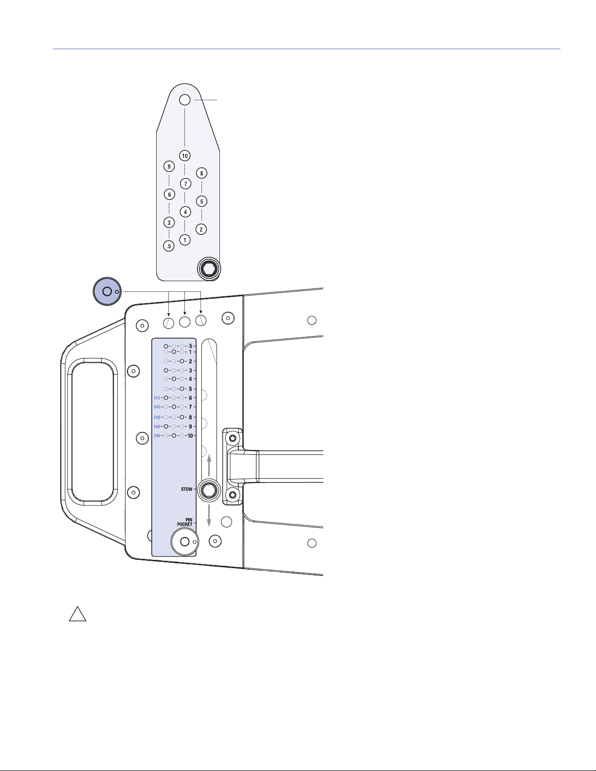
Rear GuideALinks attach at splay angles of 0.5 to 10 degrees. The labels next to the rear GuideALinks indicate the splay angle
between cabinets and provide a guide for which of the three pinning positions to use to secure the links (see Figure 1 on
page 21). As the links are moved down, the splay angle increases. To stow the rear GuideALinks, move them all the way down
to STOW and pin them to the center pin position.
NOTE: The splay angles listed on the GuideALink labels are for relative angles between the center axes of the
linked units. For example, setting the GuideALinks to 5 degrees yields a 5-degree downtilt of the lower unit to
the upper unit. How the loudspeakers relate to the floor, stage, and seating angles in the venue depends on the orientation of the grid, the angles of the loudspeakers in the array above them, and other factors. MAPP prediction software
should be used to calculate optimum splay angles for loudspeakers and to predict coverage patterns for arrays.
20
Page 21
STOW
!
MG-LEOPARD/900 GRID ASSEMBLY GUIDE
Figure 1: LEOPARD Rear GuideALinks Label, Splay Angles and Pinning Positions
CAUTION: GuideALinks must be secured with the included quick-release pins. At no time should the weight of
the loudspeaker rest on the GuideALink knobs when the links are fully extended (without the pins inserted). Guide-
ALink knobs are for extending and retracting the links only.
21
Page 22
CHAPTER 4: LOUDSPEAKER GUIDEALINKS
LEOPARD Splay Angles for Top Flown Cabinets
When flying LEOPARDs below the 900-LFC, MG-LEOPARD/900 grid, or MTF-LYON/LEOPARD transition frame, splay
angles of –4.5 to +10 degrees are possible for the top cabinet with the following GuideALink configurations.
Table 1: LEOPARD (Top Cabinet) GuideALink Configurations
Rear
GuideALinks
Set To
.5° 0° –4.5°
1° 0° –4°
2° 0° –3°
3° 0° –2°
4° 0° –1°
5° 0° 0°
6° 0° 1°
7° 0° 2°
8° 0° 3°
9° 0° 4°
10° 0° 5°
6° +5° 6°
7° +5° 7°
8° +5° 8°
9° +5° 9°
10° +5° 10°
Front
GuideALinks
Set To
Resulting Angle
of Attachment
NOTE: When flying LEOPARDs from the MG-LEOPARD/900 grid, a splay angle of 0 degrees is recommended
for the top cabinet (rear GuideALinks set to 5, front GuideALinks set to 0) to ensure that the cabinet aligns with
any lasers or inclinometers mounted on the grid. To add tilt to the top cabinet, the actual grid should instead be tilted
with motors attached to the front and rear of the grid. If just one motor is available, you can attach it to one of the 13
center pickup points offset from the center of the grid to achieve the desired tilt (see “Using MAPP to Calculate Single
Pickup Points” on page 41).
22
Page 23
MG-LEOPARD/900 GRID ASSEMBLY GUIDE
900-LFC GUIDEALINKS
When equipped with the MRK-900 rigging kit, the 900-LFC includes six captive GuideALinks and six mating link slots that
link to adjacent units in flown and groundstacked arrays. Located at the top of the cabinet, GuideALinks extend up and into
the link slots of the cabinet above it, or into the link slots of the MG-LEOPARD/900 grid, making it easy to link cabinets once
they are stacked. GuideALinks extend and retract with knobs and are secured with two quick-release pins: one each in the
top and bottom cabinets. GuideALinks accommodate reversed units for cardioid arrays. The MRK-900 rigging kit includes
eight 5/16 x 0.63-inch quick-release pins (black button) (PN 134.024).
900-LFCs with MRK-900 Rigging Kit, GuideALinks and Quick-Release Pins, Exploded View
23
Page 24
CHAPTER 4: LOUDSPEAKER GUIDEALINKS
FLOWN:
LEOPARD or 900-LFC LINK
FLOWN:
LEOPARD LINK
FLOWN:
900-LFC LINK
MG-LEOPARD/900
Multipurpose Grid
MAXIMUM DOWNTILT
MAXIMUM UPTILT
GROUNDSTACK
DOWNTILT / UPTILT 3º to 8º
STOW
B
A
GROUNDSTACK
LINK
GROUNDSTACK
LINK
STOW
B
A
MAXIMUM DOWNTILT
MAXIMUM UPTILT
MAXIMUM DOWNTILT
MAXIMUM UPTILT
The 900-LFC’s GuideALinks accommodate both 900-LFCs and LEOPARDs without transition hardware. The front and rear
GuideALinks are used when flying the 900-LFC below the MG-LEOPARD/900 grid, or when flying it below another 900-LFC
(see Figure 2). The configuration of the 900-LFC’s GuideALinks, front and rear, determines its splay angle.
Figure 2: Flown 900-LFC with GuideALink Attachments
The 900-LFC’s four corner link slots on the bottom of the cabinet accept GuideALinks from flown 900-LFCs. The front and
middle link slots accept LEOPARD GuideALinks when flying LEOPARDs below the 900-LFC (see Figure 2). The configuration
of LEOPARD’s GuideALinks, front and rear, determines its splay angle.
24
Page 25
MG-LEOPARD/900 GRID ASSEMBLY GUIDE
FLOWN:
LEOPARD or 900-LFC LINK
FLOWN:
LEOPARD LINK
FLOWN:
900-LFC LINK
MG-LEOPARD/900
Multipurpose Grid
MAXIMUM DOWNTILT
MAXIMUM UPTILT
GROUNDSTACK
DOWNTILT / UPTILT 3º to 8º
STOW
B
A
GROUNDSTACK
LINK
GROUNDSTACK
LINK
STOW
B
A
MAXIMUM DOWNTILT
MAXIMUM UPTILT
MAXIMUM DOWNTILT
MAXIMUM UPTILT
!
The 900-LFC’s front and middle link slots also accept links from the MG-LEOPARD/900 grid when groundstacking the
900-LFC (see Figure 3). The configuration of the grid’s links, whether set to A or B, determines the angle of attachment for
the groundstacked 900-LFC (see “Configuring GuideALinks for the MG-LEOPARD/900 Grid” on page 57).
Figure 3: Groundstacked 900-LFC with GuideALink Attachments
The 900-LFC’s front and middle GuideALinks are used when stacking LEOPARDs on top of the 900-LFC (see Figure 3).
CAUTION: Do not use the 900-LFC’s middle GuideALinks when flying the loudspeaker below the MG-
LEOPARD/900 grid or when flying it below another 900-LFC. Always use the front and rear GuideALinks when
flying the 900-LFC.
25
Page 26
CHAPTER 4: LOUDSPEAKER GUIDEALINKS
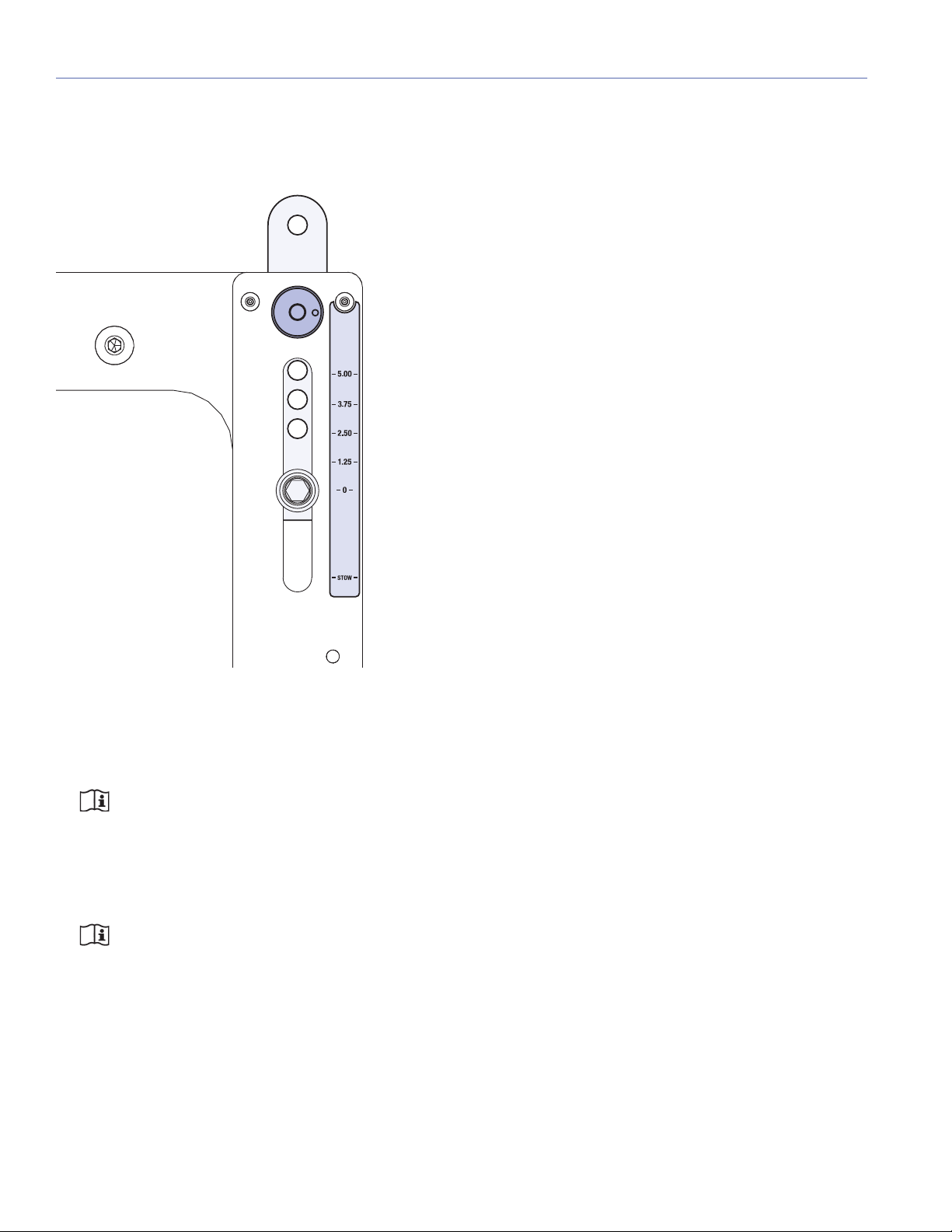
900-LFC Splay Angles
Front and rear GuideALinks attach at angles of 0.00, 1.25, 2.50, 3.75, or 5.00 degrees, thereby allowing curved arrays for the
900-LFC. Because the 900-LFC GuideALinks are symmetrical, curved arrays can also include cardioid configurations.
900-LFC Front GuideALinks Label
The labels next to the front and rear GuideALinks indicate the splay angle between cabinets (when the opposing links are set
to 0 degrees). As the links are moved up, the splay angle increases. To stow the GuideALinks, move them all the way down
to STOW and pin them.
NOTE: When flying 900-LFCs from the MG-LEOPARD/900 grid, a splay angle of 0 degrees is recommended
for the top cabinet (rear GuideALinks set to 0, front GuideALinks set to 0) to ensure that the cabinet aligns with
any lasers or inclinometers mounted on the grid. To add tilt to the top cabinet, the actual grid should instead be tilted
with motors attached to the front and rear of the grid. If just one motor is available, attach it to one of the 13 center
pickup points offset from the center of the grid to achieve the desired tilt (see “Using MAPP to Calculate Single
Pickup Points” on page 41).
NOTE: The curved array capability of the 900-LFC is provided to complement (aesthetically) the curvature of
adjacent LEOPARD, LYON, and LEO-M arrays, and to ensure that the physical cabinets of the 900-LFC array
do not obstruct the neighboring array's coverage. Curved 900-LFC arrays do not provide directionality for low-frequency content.
26
Page 27
CHAPTER 5: MG-LEOPARD/900 MULTIPURPOSE GRID
5/8-inch or 3/4-inch shackles
required for pickup points
!
!
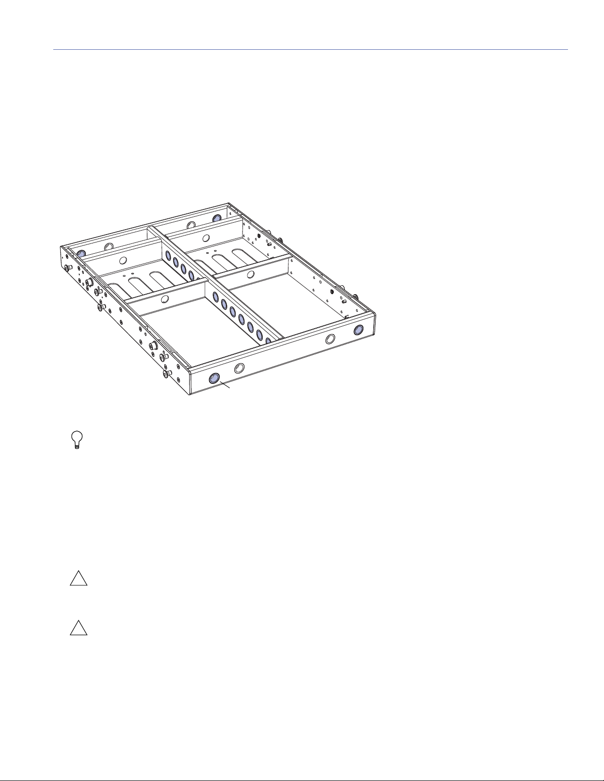
With some restrictions, the optional MG-LEOPARD/900 multipurpose grid flies arrays of up to:
■ 23 LEOPARDs at a 5:1 safety factor
■ 20 LEOPARDs at a 7:1 safety factor
■ 16 900-LFCs at a 5:1 safety factor
■ 11 900-LFCs at a 7:1 safety factor
MG-LEOPARD/900 Grid (Valid Pickup Points Highlighted in Blue)
TIP: The MG-LEOPARD/900 grid supports mixed arrays of LEOPARDs and 900-LFCs without transition hard-
ware. The grid can also be used for groundstacks.
The MG-LEOPARD/900 grid accommodates a variety of pickup configurations with its four corner and 13 center pickup
points. To add tilt to the array, attach motors to the front and rear of the grid. If just one motor is available, attach it to one of
the 13 center pickup points offset from the center of the grid to achieve the desired tilt (see “Using MAPP to Calculate Single
Pickup Points” on page 41). The grid can also be oriented to provide either maximum array downtilt or maximum array uptilt
(see “Grid Orientation for Flown Arrays” on page 33).
The MG-LEOPARD/900 grid includes attachment points to accommodate brackets and adapters for lasers and inclinometers (see Appendix B, “Laser Bracket”).
CAUTION: Always use the 5/16 x 0.875-inch quick-release pins (red button) included with the MG-LEOPARD/
900 grid to secure the attached LEOPARD or 900-LFC. Do not use the 5/16 x 0.063-inch quick-release pins (black
button) included with the loudspeakers in the grid as they are shorter and will not lock in place.
CAUTION: Always use properly rated rigging hardware. The MG-LEOPARD/900 grid requires 5/8-inch or 3/4-
inch shackles for its pickup points.
27
Page 28

CHAPTER 5: MG-LEOPARD/900 MULTIPURPOSE GRID
!
CAUTION: Potential risk of personal injury and damage to equipment. The two holes to the left and right of
the center pickup bar are for aiming lasers or inclinometers (see, Appendix B, “Laser Bracket”). These holes are
not rated to support the weight of the array and should not be used as pickup points.
TIP: The MG-LEOPARD/900 grid can travel installed on top of LEOPARD stacks on the MCF-LEOPARD caster
frame, or on top of 900-LFC stacks with the MCF-900 caster frame.
MG-LEOPARD/900 GRID KIT CONTENTS
MG-LEOPARD/900 Grid Kit, PN 40.243.080.01
Quantity Part Number Item
1 45.243.080.01 MG-LEOPARD/900 grid
10 134.025 5/16 x 0.875-inch quick-
release pins (red button)
28
Page 29

MG-LEOPARD/900 GRID DIMENSIONS
24.70
[627 mm]
20.00
[508 mm]
17x Ø0.91
[Ø23 mm]
26.50
[673 mm]
32.50
[826 mm]
28.00
[711 mm]
2.00
[51 mm]
33.50
[851 mm]
1.18
[30 mm]
8.27
[210 mm]
8x Ø0.28
[Ø7 mm]
3.00
[76 mm]
3° to 8°
Optional
Angle Feet
for Groundstack Tilt
MG-LEOPARD/900 GRID ASSEMBLY GUIDE
MG-LEOPARD/900 Grid Dimensions
MG-LEOPARD/900 Grid Weight: 60.5 lbs (27.5 kg)
29
Page 30

CHAPTER 5: MG-LEOPARD/900 MULTIPURPOSE GRID
!
!
MG-LEOPARD/900 GRID LOAD RATINGS
Table 2 lists the maximum number of loudspeakers that can be flown from the MG-LEOPARD/900 grid. These load ratings are
only supported when observing the “Additional Requirements for MG-LEOPARD/900 Grid Load Ratings” on page 32. For load
ratings for LEOPARD/900-LFC mixed arrays, see “MG-LEOPARD/900 Grid Load Ratings for Mixed Arrays” on page 31.
Table 2: MG-LEOPARD/900 Grid Load Ratings
Grid Configuration Maximum Load
5:1 Safety Factor
MG-LEOPARD/900
multipurpose grid
(2, 3, or 4 pickup
points)
MG-LEOPARD/900
multipurpose grid
(single pickup point,
single motor)
Splay Angle
Requirements?
No
Ye s
Splay Angle
Requirements?
No
Ye s
Splay Angle
Requirements?
No
Splay Angle
Requirements?
No
Maximum Flown
LEOPARDs
16
1,200 lbs (545 kg)
23
1,725 lbs (782 kg)
REQUIREMENTS: LEOPARDs in top half of array with
splay angles of 2° or less; LEOPARDs in third
quarter of array (from top) with splay angles of 7°
or less; LEOPARDs in last quarter of array with
any splay angle.
Maximum
Flown 900-LFCs
13
2,067 lbs (940 kg)
16
2,544 lbs (1,156 kg)
REQUIREMENTS: All cabinets with splay angles of 0°.
Maximum
Flown LEOPARDs
16
1,200 lbs (544 kg)
Maximum Flown
900-LFCs
13
2,080 lbs (943 kg)
REQUIREMENTS: LEOPARDs in top half of array with
splay angles of 2° or less; LEOPARDs in third
quarter of array (from top) with splay angles of 7°
or less; LEOPARDs in last quarter of array with
any splay angle.
REQUIREMENTS: All cabinets with splay angles of 0°.
Maximum Load
7:1 Safety Factor
Maximum Flown
LEOPARDs
13
975 lbs (443 kg)
20
1,500 lbs (680 kg)
Maximum Flown
900-LFCs
10
1,590 lbs (723 kg)
11
1,749 lbs (795 kg)
Maximum Flown
LEOPARDs
12
900 lbs (408 kg)
Maximum Flown
900-LFCs
10
1,600 lbs (726 kg)
CAUTION: Potential risk of personal injury and damage to equipment. Do not exceed load ratings.
CAUTION: The load ratings in Table 2 are reduced for pull-back configurations with the PBF-LEOPARD pull-
back frame.
NOTE: Additional array configurations for the MG-LEOPARD/900 grid are possible. Use MAPP prediction soft-
ware to verify whether configurations exceed load ratings. You can also use MAPP to verify whether configurations meet BGV C1 requirements.
TIP: You can use load sensors to measure load points for the MG-LEOPARD/900 grid.
30
Page 31

MG-LEOPARD/900 GRID ASSEMBLY GUIDE
!
!
MG-LEOPARD/900 Grid Load Ratings for Mixed Arrays
Table 3 lists the maximum number of loudspeakers that can be flown in LEOPARD/900-LFC mixed arrays from the
MG-LEOPARD/900 grid. These load ratings are only supported when observing the “Additional Requirements for
MG-LEOPARD/900 Grid Load Ratings” on page 32.
Table 3: MG-LEOPARD/900 Grid Load Ratings with 900-LFCs and LEOPARDs
Grid Configuration Maximum Load
5:1 Safety Factor
MG-LEOPARD/900
multipurpose grid
(2, 3 or 4 pickup
points)
MG-LEOPARD/900
multipurpose grid
(single pickup point,
single motor)
Number of Flown
900-LFCs
REQUIREMENTS: (1) No splay angle requirements for 900-LFCs. (2) No splay angle requirements for LEOPARDs.
114 11
212 10
312 10
411 10
Number of Flown
900-LFCs
REQUIREMENTS: (1) 900-LFCs with splay angles of 0°. (2) LEOPARDs in top half of array with splay angles of 2° or less;
LEOPARDs in third quarter of array (from top) with splay angles of 7° or less; LEOPARDs in last quarter of array with any
splay angle.
122 18
221 17
320 17
419 15
Number of Flown
900-LFCs
REQUIREMENTS: (1) No splay angle requirements for 900-LFCs. (2) No splay angle requirements for LEOPARDs.
114 11
212 10
312 10
411 10
Maximum Flown
LEOPARDs
Maximum Flown
LEOPARDs
Maximum Flown
LEOPARDs
Maximum Load
7:1 Safety Factor
Maximum Flown
LEOPARDs
Maximum Flown
LEOPARDs
Maximum Flown
LEOPARDs
CAUTION: Potential risk of personal injury and damage to equipment. Do not exceed load ratings.
CAUTION: The load ratings in Table 3 are reduced for pull-back configurations with the PBF-LEOPARD pull-
back frame.
NOTE: Additional array configurations for the MG-LEOPARD/900 grid are possible. Use MAPP prediction soft-
ware to verify whether configurations exceed load ratings. You can also use MAPP to verify whether configura-
tions meet BGV C1 requirements.
31
Page 32

CHAPTER 5: MG-LEOPARD/900 MULTIPURPOSE GRID
!
ADDITIONAL REQUIREMENTS FOR MG-LEOPARD/900 GRID LOAD RATINGS
The load ratings in Table 2 on page 30 and Table 3 on page 31 are only supported when the following requirements are
observed:
■ Always use properly rated rigging hardware. The MG-LEOPARD/900 grid requires 5/8-inch or 3/4-inch shackles for its
pickup points.
■ Supported pickup points are: single center point, two center points, three points, and four corner points. For more infor-
mation, see “MG-LEOPARD/900 Pickup Configurations” on page 35.
■ If a bridle is used between pickup points, the bridle angle at the apex must not be greater than 90 degrees.
■ The minimum supported leg length for front-to-rear bridle attachments is 23 inches (584 mm). The minimum supported
leg length for side-to-side bridle attachments is 15 inches (381 mm). Using a bridle leg shorter than the recommended
length reduces the load rating and may damage the MG-LEOPARD/900 grid.
■ The array should not be pulled from points other than those on the grid (except when using the PBF-LEOPARD for pull-
back).
CAUTION: The load ratings in Table 2 on page 30 and Table 3 on page 31 are reduced for pull-back configura-
tions with the PBF-LEOPARD pull-back frame.
■ The maximum number of LEOPARD or 900-LFC loudspeakers that can be flown is based on a weight of 75 lbs (34.0 kg)
for each LEOPARD cabinet and 159 lbs (72.1 kg) for each 900-LFC cabinet.
■ The maximum load ratings regard the MG-LEOPARD/900 grid and flown loudspeakers as a system, including GuideA-
Links and quick-release pins. Thus, the maximum stress point could change from one element to another in the system.
■ The weight of any additional items suspended with the array, such as downfill loudspeakers, transition and pull-back
hardware, and cable, must be considered when calculating the maximum load.
■ The weight of the MG-LEOPARD/900 grid has not been included in Table 2 on page 30. The table rates the maximum
load for the grid. Pickup points and motors that will suspend the grid must be rated to the support the total weight of the
grid (60.5 lbs, 27.5 kg) and its suspended loudspeakers (see Table 2 on page 30).
32
Page 33

CHAPTER 6: FLYING ARRAYS
FLOWN:
LEOPARD or 900-LFC LINK
FLOWN:
LEOPARD LINK
FLOWN:
900-LFC LINK
MG-LEOPARD/900
Multipurpose Grid
MAXIMUM DOWNTILT
MAXIMUM UPTILT
GROUNDSTACK
DOWNTILT / UPTILT 3º to 8º
STOW
B
A
GROUNDSTACK
LINK
GROUNDSTACK
LINK
STOW
B
A
MAXIMUM DOWNTILT
MAXIMUM UPTILT
MAXIMUM DOWNTILT
MAXIMUM UPTILT
Front
MAXIMUM DOWNTILT
MAXIMUM UPTILT
A
A
MAXIMUM DOWNTILT
MAXIMUM UPTILT
GROUNDSTACK
DOWNTILT / UPTILT 3º to 8º
GROUNDSTACK
LINK
GROUNDSTACK
LINK
LEOPARD or 900-LFC LINK
FLOWN:
FLOWN:
LEOPARD LINK
FLOWN:
900-LFC LINK
STOW
B
STOW
B
MG-LEOPARD/900
Multipurpose Grid
MAXIMUM DOWNTILT
MAXIMUM UPTILT
Front
GRID ORIENTATION FOR FLOWN ARRAYS
The MG-LEOPARD/900 grid can be oriented to locate the array’s center of gravity closer to the front or rear of the grid, to
achieve a few more degrees of downtilt or uptilt for flown arrays. The grid’s orientation is also important when accommodating groundstacks with downtilt or uptilt (see “Grid Orientation and Groundstacks” on page 58).
TIP: To add tilt to the grid, you can attach motors to the front and rear of the grid. If just one motor is available,
attach it to one of the 13 center pickup points offset from the center of the grid to achieve the desired tilt (see
“Using MAPP to Calculate Single Pickup Points” on page 41).
MG-LEOPARD/900 Grid Oriented for Maximum Array Downtilt (Forward)
When the MG-LEOPARD/900 grid is oriented forward with the attached loudspeaker near the front of the grid, the array’s center
of gravity is located closer to the front of the grid, thereby allowing the rear pickup points to achieve maximum array downtilt.
MG-LEOPARD/900 Grid Oriented for Maximum Array Downtilt (Forward)
MG-LEOPARD/900 Grid Oriented for Maximum Array Uptilt (Rearward)
When the MG-LEOPARD/900 grid is oriented rearward with the attached loudspeaker near the rear of the grid, the array’s center
of gravity is located closer to the rear of the grid, thereby allowing the front pickup points to achieve maximum array uptilt.
MG-LEOPARD/900 Grid Oriented for Maximum Array Uptilt (Rearward)
33
Page 34

CHAPTER 6: FLYING ARRAYS
!
!
ATTACHING FLOWN ARRAYS TO THE MG-LEOPARD/900
The MG-LEOPARD/900 grid has six bottom link slots, three on each side of the grid, that accept GuideALinks from the top
LEOPARD or 900-LFC cabinet in the array. The configuration of the GuideALinks for the top cabinet determines the angle of
its attachment (see “LEOPARD Splay Angles” on page 20 and “900-LFC Splay Angles” on page 26). The grid includes 10
5/16 x 0.875-inch quick-release pins (red button) for securing the top cabinet and configuring the grid’s links for groundstack attachments.
MG-LEOPARD/900 Grid with LEOPARDs, Exploded View
CAUTION: Always use the 5/16 x 0.875-inch quick-release pins (red button) included with the MG-LEOPARD/900
grid to secure the attached LEOPARD or 900-LFC. Do not use the 5/16 x 0.063-inch quick-release pins (black
button) included with the loudspeakers in the grid as they are shorter and will not lock in place.
CAUTION: Do not use the 900-LFC’s middle GuideALinks when flying the loudspeaker below the MG-
LEOPARD/900 grid or when flying it below another 900-LFC. Always use the front and rear GuideALinks when
flying the 900-LFC.
NOTE: When flying loudspeakers from the MG-LEOPARD/900 grid, a splay angle of 0 degrees is recom-
mended for the top cabinet (for LEOPARD, rear GuideALinks set to 5, front GuideALinks set to 0; for the
900-LFC, rear GuideALinks set to 0, front GuideALinks set to 0) to ensure that the cabinet aligns with any lasers or
inclinometers mounted on the grid. To add tilt to the top cabinet, the actual grid should instead be tilted with motors
attached to the front and rear of the grid. If just one motor is available, attach it to one of the 13 center pickup points
offset from the center of the grid to achieve the desired tilt (see “Using MAPP to Calculate Single Pickup Points” on
page 41).
34
Page 35

MG-LEOPARD/900 GRID ASSEMBLY GUIDE
!
!
!
!
MG-LEOPARD/900 PICKUP CONFIGURATIONS
The MG-LEOPARD/900 grid accommodates a variety of pickup configurations with its four corner and 13 center pickup points.
For greater stability, bridles, suspended from a single motor and attached to two grid pickup points, are recommended. To add
tilt to the array, attach motors to the front and rear of the grid. If just one motor is available, attach it to one of the 13 center
pickup points offset from the center of the grid to achieve the desired tilt (see “Using MAPP to Calculate Single Pickup Points”
on page 41).
CAUTION: When flying MG-LEOPARD/900 arrays, make sure the motors and ceiling attachment point (above
the hook) are rated to hold the total weight of the grid and array, including any additional items suspended with
the array, such as downfill loudspeakers, pull-back accessories, transition accessories, and cable.
CAUTION: Always use properly rated rigging hardware. The MG-LEOPARD/900 grid requires 5/8-inch or 3/4-
inch shackles for its pickup points.
CAUTION: When using bridles between pickup points on the MG-LEOPARD/900, the angle of the bridle at the
apex should not be greater than 90 degrees to avoid damaging the grid.
CAUTION: Potential risk of personal injury and damage to equipment. The two holes to the left and right of
the center pickup bar are for aiming lasers or inclinometers (see, Appendix B, “Laser Bracket”). These holes are
not rated to support the weight of the array and should not be used as pickup points.
35
Page 36

CHAPTER 6: FLYING ARRAYS
!
Pickup Configurations with One Motor
The MG-LEOPARD/900 grid supports the following pickup configurations with one motor.
1 Motor – 1 Pickup Point (Left); 1 Motor – 2 Pickup Points, Front-to-Rear Bridle (Right)
CAUTION: The minimum supported leg length for front-to-rear bridle attachments is 23 inches (584 mm).
TIP: For configurations with a single pickup point and single motor, you can add tilt by adjusting the placement
of the pickup point.To add downtilt, attach the motor to a pickup point closer to the rear of the grid. To add
uptilt, attach the motor to a pickup point closer to the front of the grid.
TIP: For configurations with a single pickup point and single motor, you can use MAPP to calculate which
pickup point to use to achieve the desired downtilt, uptilt, or no tilt. For more information, see “Using MAPP to
Calculate Single Pickup Points” on page 41.
36
Page 37

MG-LEOPARD/900 GRID ASSEMBLY GUIDE
!
Pickup Configurations with Two Motors
The MG-LEOPARD/900 grid supports the following pickup configurations with two motors.
2 Motors – 2 Pickup Points, Front and Rear (Left); 2 Motors – 2 Pickup Points, Front and Rear Bridles (Right)
CAUTION: The minimum supported leg length for side-to-side bridle attachments is 15 inches (381 mm).
37
Page 38

CHAPTER 6: FLYING ARRAYS
!
!
2 Motors – 3 Pickup Points, Rear Bridle (Left); 2 Motors – 3 Pickup Points, Front Bridle (Right)
CAUTION: The minimum supported leg length for side-to-side bridle attachments is 15 inches (381 mm).
CAUTION: For configurations with two motors, three pickup points, and a bridle, make sure to place the bridle
on the side with the higher load value.
38
Page 39

MG-LEOPARD/900 GRID ASSEMBLY GUIDE
!
!
!
Pickup Configurations with Three Motors
The MG-LEOPARD/900 grid supports the following pickup configurations with three motors.
3 Motors – 4 Pickup Points, Front Bridle (Left); 3 Motors – 3 Pickup Points, Rear bridle, Front Vee Plate (Right)
CAUTION: The minimum supported leg length for side-to-side bridle attachments is 15 inches (381 mm).
CAUTION: For configurations with three motors, four pickup points, and a bridle, make sure to place the two
motors on the side with the higher load value.
CAUTION: For configurations with the MVP motor Vee plate, which provides horizontal aiming of the array,
make sure to place the Vee plate on the side with the lower load value. For more information, see Chapter 7,
“MVP Motor Vee Plate.”
39
Page 40

CHAPTER 6: FLYING ARRAYS
!
Pickup Configurations with Four Motors
The MG-LEOPARD/900 grid supports the following pickup configurations with four motors.
4 Motors – 4 Pickup Points (Left); 4 Motors – 3 Pickup Points, Rear Bridle, Front Vee Plate (Right)
CAUTION: For configurations with the MVP motor Vee plate, which provides horizontal aiming of the array,
make sure to place the Vee plate on the side with the higher lower value. For more information, see Chapter 7,
“MVP Motor Vee Plate.”
40
Page 41

MG-LEOPARD/900 GRID ASSEMBLY GUIDE
USING MAPP TO CALCULATE SINGLE PICKUP POINTS
The MG-LEOPARD/900 grid has a center pickup bar with 13 pickup points. For configurations with a single pickup point and
single motor, you can use MAPP prediction software to calculate which pickup point to use to achieve the desired downtilt,
uptilt, or no tilt.
To calculate the single pickup point with MAPP:
1. In MAPP, choose Insert > Insert Flown Loudspeaker System.
2. In the Flown Loudspeaker System dialog box, in the elements list, do the following:
■ At the top of the Loudspeaker System Elements section, set the grid to one of the following options, depending on
whether a LEOPARD or 900-LFC is attached to the grid, and whether downtilt or uptilt is required:
– MG-LEOPARD/900 (LEOPARD Forward)
– MG-LEOPARD/900 (LEOPARD Rearward)
– MG-LEOPARD/900 (900-LFC Forward)
– MG-LEOPARD/900 (900-LFC Rearward)
■ To insert additional loudspeakers, click Add Element.
■ To remove a loudspeaker, click the loudspeaker to select it and click Remove Element.
■ To specify the splay angle for a loudspeaker, click in the Splay column and select an angle from the menu (for LEOPARD,
choose from –0.5 to –15 degrees; for the 900-LFC, choose –1.25, –2.50, –3.75, or –5.00 degrees).
3. To specify the grid tilt, in the Rotation About Reference Point section, enter an angle amount. Negative angles yield
downtilt. Positive angles yield uptilt. The Total splay angles for the loudspeakers (relative to horizontal) update.
4. Click Apply and Close. The flown loudspeaker system is inserted in the Sound Field.
5. Select View > Array COG. In the Sound Field, a magenta line representing the array’s center of gravity is displayed.
6. In the Sound Field, use the Zoom tool to draw a rectangle around the grid. The center of gravity line indicates the pickup
point to use to achieve the specified grid tilt amount.
7. Choose View > Center Line. Loudspeaker output lines are displayed in the Sound Field.
8. Adjust further, if necessary, the number of loudspeakers, loudspeaker splay angles, and grid tilt until the system’s acoustical requirements are met and the center of gravity aligns with one of the grid’s center pickup points.
41
Page 42

CHAPTER 6: FLYING ARRAYS
42
Page 43

CHAPTER 7: MVP MOTOR VEE PLATE
Front View
Top View
!
The optional MVP motor Vee plate fine-tunes the horizontal aim of LEOPARD and 900-LFC arrays ±16 degrees. The bottom
of the Vee plate attaches to the MG-LEOPARD/900 grid’s frontmost or rearmost point on the center pickup bar, while the top
corners of the Vee plate attach to two motors, which, when adjusted, affect the horizontal rotation of the grid. The Vee plate’s
attachment points require 3/4-inch or 7/8-inch shackles. The Vee plate should always be placed on the grid side (front or rear)
with the lower load value.
MVP Motor Vee Plate Attached to MTG-LEOPARD/900 Grid
MVP Motor Vee Plate, Pulling Up on Either Motor Rotates the Grid
CAUTION: Always use properly rated rigging hardware. The MVP motor Vee plate requires 3/4-inch or 7/8-inch
shackles for its attachment points.
43
Page 44

CHAPTER 7: MVP MOTOR VEE PLATE
!
!
CAUTION: The MVP motor Vee plate should always be placed on the grid side (front or rear) with the lower
load value.
NOTE: The MVP motor Vee plate is compatible with any Meyer Sound grid with front and rear center pickup
points.
MVP MOTOR VEE PLATE KIT CONTENTS
MVP Motor Vee Plate Kit, PN 40.215.184.01
Quantity Part Number Item
1 45.215.184.01 MVP motor Vee plate
MVP Motor Vee Plate Weight: 20 lbs (9.1 kg)
MVP MOTOR VEE PLATE LOAD RATINGS
The MVP motor Vee plate has the following maximum load ratings:
■ 7,129 lbs (3234 kg) at a 5:1 safety factor
■ 5,092 lbs (2310 kg) at a 7:1 safety factor
CAUTION: Potential risk of personal injury and damage to equipment. Do not exceed load ratings.
44
Page 45

CHAPTER 8: MTF-LYON/LEOPARD TRANSITION FRAME
!
!
!
With some restrictions, the optional MTF-LYON/LEOPARD transition frame flies up to 8 LEOPARDs at a 7:1 safety factor below
LYON arrays for downfill. The transition frame attaches to the bottom cabinet in the LYON array at an angle of 0 degrees and
is secured with the quick-release pins included with LYON. The top LEOPARD cabinet attaches to the transition frame’s inner
link slots and is secured with four 5/16 x 0.875-inch quick-release pins (red button) included with the transition frame. The configuration of GuideALinks for the top LEOPARD cabinet determines the angle of its attachment, from –4.5 to +10 degrees. The
MTF-LYON/LEOPARD transition frame is collapsible for easy transport (see “Collapsing the MTF-LYON/LEOPARD Transition
Frame” on page 47) and also includes rear pickup points for pull-back and pull-up (see “Using the MTF-LYON/LEOPARD Transition Frame for Pull-Back and Pull-Up” on page 49).
MTF-LYON/LEOPARD Transition Frame with LEOPARDs flown below LYON Array, Exploded View
CAUTION: When flying combined arrays, the total weight of the array, including any transition and pull-back
hardware, should be calculated before the array is flown to verify that the weight does not exceed the load ratings for the MTG-LYON grid. For more information, refer to the MTG-LYON Assembly Guide (PN 05.232.097.01) available at www.meyersound.com
CAUTION: Always use the 5/16 x 0.875-inch quick-release pins (red button) included with the MTF-
LYON/LEOPARD transition frame to secure the attached LEOPARD. Do not use the 5/16 x 0.063-inch quickrelease pins (black button) included with LEOPARD in the transition frame as they are shorter and will not lock in place.
CAUTION: Always use properly rated rigging hardware. The MTF-LYON/LEOPARD transition frame requires
1/2-inch or 5/8-inch shackles for its pickup points.
TIP: The MTF-LYON/LEOPARD transition frame can travel installed on top of LEOPARD stacks on the
MCF-LEOPARD caster frame.
.
45
Page 46

CHAPTER 8: MTF-LYON/LEOPARD TRANSITION FRAME
Ø0.88
[Ø22 mm]
Expanded
Collapsed
(Transport)
34.79
[884 mm]
21.98
[558 mm]
7.51
[191 mm]
16.77
[426 mm]
16.60
[422 mm]
28.79
[731 mm]
MTF-LYON/LEOPARD TRANSITION FRAME KIT CONTENTS
MTF-LYON/LEOPARD Transition Frame Kit, PN 40.232.140.01
Quantity Part Number Item
1 45.232.140.01 MTF-LYON/LEOPARD
transition frame
8 134.025 5/16 x 0.875-inch quick-
release pins (red button)
MTF-LYON/LEOPARD TRANSITION FRAME DIMENSIONS
MTF-LYON/LEOPARD Transition Frame Dimensions
MTF-LYON/LEOPARD Transition Frame Weight: 71 lbs (32.2 kg)
46
Page 47

MG-LEOPARD/900 GRID ASSEMBLY GUIDE
COLLAPSING THE MTF-LYON/LEOPARD TRANSITION FRAME
The MTF-LYON/LEOPARD transition frame collapses horizontally so it can travel installed on top of LEOPARD stacks on the
MCF-LEOPARD caster frame. When the transition frame is collapsed, it occupies a smaller footprint than the MCF-LEOPARD
caster frame.
MTF-LYON/LEOPARD Transition Frame Collapsed
Before attaching the MTF-LYON/LEOPARD transition frame to a LYON array, simply expand the frame and lock it with the
included 5/16 x 0.875-inch quick-release pins (red button).
MTF-LYON/LEOPARD Transition Frame Expanded, Exploded View
47
Page 48

CHAPTER 8: MTF-LYON/LEOPARD TRANSITION FRAME
!
!
MTF-LYON/LEOPARD TRANSITION FRAME LOAD RATINGS (LOUDSPEAKER)
Table 4 lists the maximum number of LEOPARDs that can be flown below LYON arrays with the MTF-LYON/LEOPARD transition frame. The LYON array configuration greatly affects the load ratings for the attached MTF-LYON/LEOPARD transition
frame. In addition, the number of LEOPARDs flown below the LYON array greatly affects the load rating for the MTG-LYON
grid. For additional grid requirements, refer to the MTG-LYON Assembly Guide (PN 05.232.097.01) available at
www.meyersound.com
/
Table 4: MTF-LYON/LEOPARD Transition Frame Load Ratings
Number of
Flown
LY ON s
610 8 10 8
79 8 10 8
89 7 10 8
99 5 10 8
10 9 5 10 8
11 9 2 9 7
12 7
13 4
14 2
15 8
16 6
17 4
18 2
.
Maximum Flown LEOPARDs
(No Restrictions)
All Splay Angles Allowed LYONs in Top Half of Array with Splay Angles of 2° or Less,
LYONs in Bottom Half of Array with Splay Angles of 5° or Less,
5:1 Safety Factor 7:1 Safety Factor 5:1 Safety Factor 7:1 Safety Factor
Maximum Flown LEOPARDs
(with Restrictions)
LEOPARDs with Any Splay Angle
94
92
9
CAUTION: Potential risk of personal injury and damage to equipment. Do not exceed load ratings.
CAUTION: When flying combined arrays, the total weight of the array, including any transition and pull-back
hardware, should be calculated before the array is flown to verify that the weight does not exceed the load ratings for the MTG-LYON grid. For more information, refer to the MTG-LYON Assembly Guide (PN 05.232.097.01) available at www.meyersound.com
.
NOTE: Additional array configurations for the MTF-LYON/LEOPARD transition frame (not shown in Table 4) are
possible. Use MAPP prediction software to verify whether configurations exceed load ratings. You can also use
MAPP to verify whether configurations meet BGV C1 requirements.
48
Page 49

MG-LEOPARD/900 GRID ASSEMBLY GUIDE
!
!
!
MTF-LYON/LEOPARD TRANSITION FRAME LOAD RATINGS (PULL-BACK)
When used for pull-back, the MTF-LYON/LEOPARD transition frame has the following maximum load ratings:
■ 1,400 lbs (635 kg) at a 5:1 safety factor
■ 1,000 lbs (454 kg) at a 7:1 safety factor
CAUTION: Potential risk of personal injury and damage to equipment. Do not exceed load ratings. To ver-
ify pull-back load ratings, see “Verifying Pull-Back Requirements in MAPP” on page 53.
CAUTION: When using the MTF-LYON/LEOPARD transition frame for pull-back, the number of flown
LEOPARDs should not exceed four. If more than four LEOPARDs are attached to the transition frame for downfill, and pull-back is required, the PBF-LEOPARD pull-back frame (attached to the bottom LEOPARD in the array)
must instead be used as the pull-back hardware.
CAUTION: The apex angle for the bridle attachment to the MTF-LYON/LEOPARD transition frame must not be
greater than 90 degrees. The minimum supported leg length for the bridle attachment to the MTFLYON/LEOPARD transition frame is 16 inches (406 mm). Using a bridle leg shorter than the recommended length
reduces the load rating and may damage the MTF-LYON/LEOPARD transition frame.
USING THE MTF-LYON/LEOPARD TRANSITION FRAME FOR PULL-BACK AND PULL-UP
The MTF-LYON/LEOPARD transition frame includes two rear pickup points that provide pull-back for extreme array downtilts. The pickup points can also be used for pull-up to expand the LYON array’s splay angles during installation so the blue
locking pins can be more easily inserted. The MTF-LYON/LEOPARD transition frame requires 1/2-inch or 5/8-inch shackles
for its pickup points.
MTF-LYON/LEOPARD Transition Frame with Pull-Back
49
Page 50

CHAPTER 8: MTF-LYON/LEOPARD TRANSITION FRAME
!
!
!
■ When the MTF-LYON/LEOPARD transition frame is used for pull-back, to tilt the array, the transition frame must be pulled
by a motor separate from and behind the MTG-LYON grid. The pull-back motor must not be attached to the grid.
CAUTION: When configuring arrays with pull-back, when in final position, the pull-back chain should not be
greater than ±30 degrees from vertical.
■ When the MTF-LYON/LEOPARD transition frame is used for pull-up, to expand the LYON array’s splay angles during
installation so the blue locking pins can be more easily inserted, the transition frame is pulled by a motor placed between
the transition frame and the RPP-LEO-M rear pull-up plate (attached to the MTG-LYON grid). For more information, refer
to the MTG-LYON Assembly Guide (PN 05.232.097.01) available at available at www.meyersound.com
.
CAUTION: When flying combined arrays, the total weight of the array, including any transition and pull-back
hardware, should be calculated before the array is flown to verify that the weight does not exceed the load ratings for the MTG-LYON grid. For more information, refer to the MTG-LYON Assembly Guide (PN 05.232.097.01) available at www.meyersound.com
.
CAUTION: Always use properly rated rigging hardware. The MTF-LYON/LEOPARD transition frame requires
1/2-inch or 5/8-inch shackles for its pickup points.
50
Page 51

CHAPTER 9: PBF-LEOPARD PULL-BACK FRAME
!
!
!
For applications requiring extreme array downtilt that are not possible with adjustments to the motors attached to the grid,
the optional PBF-LEOPARD pull-back frame can be attached to the bottom cabinet in LEOPARD arrays and pulled by a separate motor. The pull-back frame is secured to the bottom cabinet with the 5/16 x 0.875-inch quick-release pins (black button) included with LEOPARD. The PBF-LEOPARD pull-back frame requires 1/2-inch shackles for its two pickup points.
PBF-LEOPARD Pull-Back Frame Attached to Bottom LEOPARD, Exploded View
CAUTION: When configuring arrays with pull-back, when in final position, the pull-back chain should not be
more than ±30 degrees from vertical.
CAUTION: When flying arrays, the total weight of the array, including any pull-back and pull-up hardware,
should be calculated before the array is flown to verify its weight does not exceed the load ratings for the
MG-LEOPARD/900 grid. For more information, see “MG-LEOPARD/900 Grid Load Ratings” on page 30.
CAUTION: Always use properly rated rigging hardware. The PBF-LEOPARD pull-back frame requires 1/2-inch
shackles for its pickup points.
TIP: The PBF-LEOPARD pull-back frame can also be used to add downtilt to LEOPARDs groundstacked on top
of the 900-LFC. For more information, see “Adding Groundstack Tilt with the PBF-LEOPARD” on page 62.
51
Page 52

CHAPTER 9: PBF-LEOPARD PULL-BACK FRAME
22.29
[566 mm]
24.92
[633 mm]
3.25
[83 mm]
6.78
[172 mm]
Ø0.81
[Ø21 mm]
!
!
PBF-LEOPARD KIT CONTENTS
PBF-LEOPARD Pull-Back Frame Kit, PN 40.243.185.01
Quantity Part Number Item
1 45.232.125.01 PBF-LEOPARD pull-back
2 134.024 5/16 x 0.63-inch quick-
PBF-LEOPARD TRANSITION FRAME DIMENSIONS
frame
release pins (black button)
PBF-LEOPARD Pull-Back Frame Dimensions
PBF-LEOPARD Transition Frame Weight: 4.9 lbs (2.2 kg)
PBF-LEOPARD TRANSITION FRAME LOAD RATINGS
The PBF-LEOPARD pull-back frame has the following maximum load ratings:
■ 1,400 lbs (635 kg) at a 5:1 safety factor
■ 1,000 lbs (454 kg) at a 7:1 safety factor
CAUTION: Potential risk of personal injury and damage to equipment. Do not exceed load ratings. To ver-
ify pull-back load ratings, see “Verifying Pull-Back Requirements in MAPP” on page 53.
CAUTION: The apex angle for the bridle attachment to the PBF-LEOPARD pull-back frame must not be greater
than 90 degrees. The minimum supported leg length for the bridle attachment to the PBF-LEOPARD pull-back
frame is 16 inches (406 mm). Using a bridle leg shorter than the recommended length reduces the load rating and
may damage the PBF-LEOPARD pull-back frame.
52
Page 53

MG-LEOPARD/900 GRID ASSEMBLY GUIDE
!
VERIFYING PULL-BACK REQUIREMENTS IN MAPP
To verify array pull-back requirements in MAPP:
1. Insert the loudspeaker array and configure loudspeaker splay angles:
■ Choose Insert > Insert Flown Loudspeaker System.
■ In the Flown Loudspeaker System dialog box, at the top of the elements list, set the grid to one of the following options,
depending on whether a LEOPARD or 900-LFC is attached to the grid, and whether downtilt or uptilt is required. The elements list is populated with loudspeakers set to default splay angles.
– MG-LEOPARD/900 (LEOPARD Forward)
– MG-LEOPARD/900 (LEOPARD Rearward)
– MG-LEOPARD/900 (900-LFC Forward)
– MG-LEOPARD/900 (900-LFC Rearward)
■ To insert a transition frame or additional loudspeakers, click Add Element.
■ To remove a loudspeaker, click the loudspeaker to select it and click Remove Element.
■ To specify the splay angle for a loudspeaker, click in the Splay column and select an angle from the menu.
2. Verify whether the array complies with the required safety rating:
■ In the Safety Limits section, select the safety rating with which the array should comply: 7:1, 5:1, or BGV C1.
■ In the Rotation About Reference Point section, reduce the Angle amount for the array (to a negative value) so that the
Front Rigging Load amount is between 0 and +10 lbs.
■ If the Load Status is green (“Loudspeaker Configuration is Within the Rated Load Capacities”), the array is within compli-
ance. Proceed to the next step.
■ If the Load Status turns red (“Loudspeaker Configuration COG is Outside of Grid Pickup Points”), the array is not within
compliance. Return to the previous step and either reduce the number of loudspeakers in the array or adjust the loudspeaker splay angles.
3. Verify the array’s pull-back requirements:
■ In the Rotation About Reference Point section, enter the actual Angle amount required for the array’s downtilt.
■ If the Front Rigging Load amount (at the bottom of the dialog box) is a positive value, no pull-back hardware is required.
■ If the Front Rigging Load amount is a negative value, pull-back hardware is required. Make sure that the Front Rigging
Load amount (the negative value) does not exceed the maximum load ratings for the pull-back hardware (see
“PBF-LEOPARD Transition Frame Load Ratings” on page 52).
CAUTION: For arrays flown from multiple motors (for example, two motors attached to the grid and one motor
attached to the pull-back frame), to achieve the greatest stability, make sure to distribute the load to all motors.
53
Page 54

CHAPTER 9: PBF-LEOPARD PULL-BACK FRAME
54
Page 55

CHAPTER 10: GROUNDSTACKING WITH THE MG-LEOPARD/900 GRID
!
With some restrictions, the MG-LEOPARD/900 grid safely groundstacks up to:
■ 7 LEOPARDs
■ 5 LEOPARDs on top of 1 900-LFC (mixed groundstack)
■ 4 LEOPARDs on top of 2 900-LFCs (mixed groundstack)
■ 3 900-LFCs
CAUTION: Potential risk of personal injury and damage to equipment. Groundstacks with extreme splay
angles that locate the stack's center of gravity outside the grid (for example, seven LEOPARDs, each with 15-
degree splay angles) are not supported.
The loudspeaker at the bottom of the groundstack is secured to the grid’s four captive GuideALinks (two per side) with the
5/16 x 0.063-inch quick-release pins (black button) included with the loudspeaker.
MG-LEOPARD/900 Grid with Groundstacked LEOPARDs, Exploded View
55
Page 56

CHAPTER 10: GROUNDSTACKING WITH THE MG-LEOPARD/900 GRID
To groundstack 900-LFCs with the MG-LEOPARD/900 grid, the 900-LFCs must be equipped with the MRK-900 rigging kit.
MG-LEOPARD/900 Grid with Groundstacked 900-LFCs, Exploded View
56
Page 57

MG-LEOPARD/900 GRID ASSEMBLY GUIDE
FLOWN:
LEOPARD or 900-LFC LINK
FLOWN:
LEOPARD LINK
FLOWN:
900-LFC LINK
MG-LEOPARD/900
Multipurpose Grid
MAXIMUM DOWNTILT
MAXIMUM UPTILT
GROUNDSTACK
DOWNTILT / UPTILT 3º to 8º
STOW
B
A
GROUNDSTACK
LINK
GROUNDSTACK
LINK
STOW
B
A
MAXIMUM DOWNTILT
MAXIMUM UPTILT
MAXIMUM DOWNTILT
MAXIMUM UPTILT
STOWB
A
GuideALink
1. Remove quick-release pin.
2. Rotate link to A, B, or Stow.
3. Insert quick-release pin.
!
CONFIGURING GUIDEALINKS FOR THE MG-LEOPARD/900 GRID
The configuration of the MG-LEOPARD/900 grid’s GuideALinks, which can be set to A, B, or STOW, determines the angle of
attachment for the loudspeaker at the bottom of the groundstack.
MG-LEOPARD/900 Grid GuideALinks
Table 5 lists the available angles of attachment for groundstacked LEOPARDs and 900-LFCs.
Table 5: MG-LEOPARD/900 Grid, GuideALink Configurations
Rear
GuideALinks
Set To
Front
GuideALinks
Set To
Resulting Angle of Attachment
for Groundstacked
LEOPARD 900-LFC
AA+5°0°
AB+2°–3°
BA+8°+3°
BB+5°0°
TIP: Groundstacks can be curved by adjusting the splay angles between the loudspeakers in the stack. For
more information, see Chapter 4, “Loudspeaker GuideALinks.” Any loudspeaker splay angles within the
groundstack are relative to the angle of attachment of the bottom cabinet.
CAUTION: Potential risk of personal injury and damage to equipment. Groundstacks with extreme splay
angles that locate the stack's center of gravity outside the grid (for example, seven LEOPARDs, each with 15-
degree splay angles) are not supported.
57
Page 58

CHAPTER 10: GROUNDSTACKING WITH THE MG-LEOPARD/900 GRID
FLOWN:
LEOPARD or 900-LFC LINK
FLOWN:
LEOPARD LINK
FLOWN:
900-LFC LINK
MG-LEOPARD/900
Multipurpose Grid
MAXIMUM DOWNTILT
MAXIMUM UPTILT
GROUNDSTACK
DOWNTILT / UPTILT 3º to 8º
STOW
B
A
GROUNDSTACK
LINK
GROUNDSTACK
LINK
STOW
B
A
MAXIMUM DOWNTILT
MAXIMUM UPTILT
MAXIMUM DOWNTILT
MAXIMUM UPTILT
Front
MAXIMUM DOWNTILT
MAXIMUM UPTILT
A
A
MAXIMUM DOWNTILT
MAXIMUM UPTILT
GROUNDSTACK
DOWNTILT / UPTILT 3º to 8º
GROUNDSTACK
LINK
GROUNDSTACK
LINK
LEOPARD or 900-LFC LINK
FLOWN:
FLOWN:
LEOPARD LINK
FLOWN:
900-LFC LINK
STOW
B
STOW
B
MG-LEOPARD/900
Multipurpose Grid
MAXIMUM DOWNTILT
MAXIMUM UPTILT
Front
!
!
GRID ORIENTATION AND GROUNDSTACKS
When groundstacking with the MG-LEOPARD/900 grid, to ensure the greatest stability, the grid should be oriented so the
center of gravity for the groundstack is near the center of the grid. For groundstacks with uptilt, the grid should be oriented
forward. For groundstacks with downtilt, the grid should be oriented rearward. The grid’s orientation also determines
whether downtilt or uptilt can be applied to the groundstack with the optional angle feet (see “Adding Groundstack Tilt with
the Angle Feet” on page 59).
MG-LEOPARD/900 Grid Oriented for Groundstack with Uptilt (Forward)
MG-LEOPARD/900 Grid Oriented for Groundstack with Downtilt (Rearward)
CAUTION: Potential risk of personal injury and damage to equipment. Groundstacks with extreme splay
angles that locate the stack's center of gravity outside the grid (for example, seven LEOPARDs, each with 15degree splay angles) are not supported.
CAUTION: To further secure large groundstacks, particularly in outdoor installations with severe wind conditions,
attach tie-downs or weights to the grid along with a safety system directly to the groundstack.
58
Page 59

MG-LEOPARD/900 GRID ASSEMBLY GUIDE
FLO
W
N
:
L
E
O
P
A
R
D or 90
0-
L
F
C L
INK
FL
O
W
N
:
L
E
O
P
A
R
D L
INK
FLO
W
N
:
90
0
L
F
C L
INK
MG-
LEOPA
R
D
/900
Mul
tipurpose Gr
id
MAXIMUM DOWNTILT
MAXIMUM UPTILT
GROUNDSTACK
DOWNTILT / UPTILT 3º to 8º
STOW
B
A
GROUNDSTACK
LINK
GROUNDSTACK
LINK
STOW
B
A
MAXIMUM DOWNTILT
MAXIMUM UPTILT
MAXIMUM DOWNTILT
MAXIMUM UPTILT
3° to 8°
ADDING GROUNDSTACK TILT WITH THE ANGLE FEET
Tilt can be added to groundstacks with the optional MG-LEOPARD/900 groundstack tilt kit (PN 40.243.163.01). The kit
includes two angle feet that attach to the rear of the MG-LEOPARD/900 grid and add from 3 to 8 degrees of tilt to the entire
groundstack. Loudspeaker splay angles within the groundstack are relative to the tilt added with the angle feet. When the
grid is oriented forward, downtilt is added to the groundstack. When the grid is oriented rearward, uptilt is added to the
groundstack.
MG-LEOPARD/900 Grid with Optional Angle Feet, 8 Degrees of Downtilt
When using the angle feet for downtilt with the 900-LFC attached to the grid, the angle setting for 3 degrees is not avail-
able. In addition, the setting for 4 degrees is only possible when the grid’s GuideALinks are configured with the rear link
set to A and the front link set to B. The angle setting for 5 degrees is only possible when the grid’s GuideALinks are configured
with the rear link set to A and the front link set to A (or B).
59
Page 60

CHAPTER 10: GROUNDSTACKING WITH THE MG-LEOPARD/900 GRID
GROUNDSTACKING LEOPARDS ON THE 900-LFC
Up to five LEOPARDs can be groundstacked on top of a single 900-LFC (when equipped with the MRK-900 rigging kit). Up
to four LEOPARDs can be groundstacked on top of two 900-LFCs. The angle of attachment for the bottom LEOPARD is determined by the configuration of the 900-LFC’s GuideALinks. When the 900-LFC’s front GuideALinks are set to 0 degrees, the
available angles for the bottom LEOPARD are 5.00, 3.25, 1.50, 0, and –1.75 degrees.
LEOPARDs Groundstacked on 900-LFC, Exploded View
60
Page 61

MG-LEOPARD/900 GRID ASSEMBLY GUIDE
!
!!
The labels next to the 900-LFC’s middle GuideALinks indicate the splay angle for the attached LEOPARD (when the 900-LFC’s
front GuideALinks are set to 0 degrees). As the links are moved down, the splay angle increases. To stow the middle GuideALinks, move them all the way down to STOW and pin them.
900-LFC Middle GuideALinks Label
CAUTION: Potential risk of personal injury and damage to equipment. Groundstacks with extreme splay
angles that locate the stack's center of gravity outside the grid (for example, seven LEOPARDs, each with 15-
degree splay angles) are not supported.
CAUTION: To further secure large groundstacks, particularly in outdoor installations with severe wind conditions,
attach tie-downs or weights to the grid along with a safety system directly to the groundstack.
61
Page 62

CHAPTER 10: GROUNDSTACKING WITH THE MG-LEOPARD/900 GRID
Adding Groundstack Tilt with the PBF-LEOPARD
The PBF-LEOPARD pull-back frame can be used to add 7.75 degrees of downtilt to LEOPARDs groundstacked on top of the
900-LFC. To achieve the downtilt, the PBF-LEOPARD is placed between the bottom LEOPARD and the 900-LFC’s middle
GuideALinks. The downtilt from the PBF-LEOPARD is added to the tilt achieved with the 900-LFC’s middle GuideALinks (see
Table 6).
Figure 4: LEOPARDs Groundstacked on 900-LFC with PBF-LEOPARD (Downtilt)
62
Page 63

MG-LEOPARD/900 GRID ASSEMBLY GUIDE
Any loudspeaker splay angles within the LEOPARD groundstack are relative to the angle of attachment of the bottom
LEOPARD cabinet.
Table 6: LEOPARD/900-LFC Groundstack, Available Downtilt
900-LFC LEOPARD Angle
Middle GuideALinks
Set To
–1.75 0 –1.75° –9.50°
0 0 0° –7.75°
1.50 0 1.50° –6.25°
3.25 0 3.25° –4.50°
5.00 0 5.00° –2.75°
Front GuideALinks
Set To
Without
PBF-LEOPARD
With
PBF-LEOPARD
63
Page 64

CHAPTER 10: GROUNDSTACKING WITH THE MG-LEOPARD/900 GRID
64
Page 65

CHAPTER 11: MCF-LEOPARD CASTER FRAME
The MCF-LEOPARD caster frame safely transports up to four LEOPARDs, making it easy to assemble and disassemble arrays
in blocks of four cabinets. The caster frame’s sturdy construction allows it to be conveniently moved with forklifts.
MCF-LEOPARD Caster Frame
The MCF-LEOPARD caster frame includes four fixed, 0-degree links that attach to the cabinet at the bottom of the stack
and are secured with the 5/16 x 0.63-inch (black button) quick-release pins included with LEOPARD. Make sure to orient the
caster frame so the taller links attach to the rear of the loudspeaker.
MCF-LEOPARD Caster Frame with LEOPARD Stack, Exploded View
65
Page 66

CHAPTER 11: MCF-LEOPARD CASTER FRAME
MCF-LEOPARD Caster Frame, (4) LEOPARDs, and MG-LEOPARD/900 Grid
TIP: Durable nylon pullover covers, sized for stacks of 3 or 4 units, are available to protect LEOPARD cabinets
during transport. Special wraparound covers are also available to accommodate stacks with grids on top.
TIP: The MG-LEOPARD/900 grid can travel installed on top of LEOPARD stacks on the MCF-LEOPARD caster
frame.
TIP: When transporting the MG-LEOPARD/900 grid on top of LEOPARD stacks on the MCF-LEOPARD caster
frame, to avoid colliding the grid with other LEOPARD stacks, attach the grid to the top LEOPARD with its front
GuideALinks set to +5 degrees and its rear GuideALinks set to 0.5 degrees, so the grid is effectively raised 1.5 inches
above the stack.
TIP: The MTF-LYON/LEOPARD transition frame can travel installed on top of LEOPARD stacks on the
MCF-LEOPARD caster frame.
66
Page 67

MCF-LEOPARD CASTER FRAME DIMENSIONS
29.75
[756 mm]
17.88
[454 mm]
19.86
[504 mm]
23.74
[603 mm]
24.53
[623 mm]
8.84
[225 mm]
6.44
[164 mm]
MG-LEOPARD/900 GRID ASSEMBLY GUIDE
MCF-LEOPARD Caster Frame Dimensions
MCF-LEOPARD Caster Frame Weight: 37 lbs (16.8 kg)
67
Page 68

CHAPTER 11: MCF-LEOPARD CASTER FRAME
900-LFC
29.75” W
27.84” D
LYO N
38.90” W
23.90” D
LYO N
38.90” W
23.90” D
LEOPARD
29.75” W
24.53” D
LEOPARD
29.75” W
24.53” D
LEOPARD
29.75” W
24.53” D
LEOPARD
29.75” W
24.53” D
900-LFC
29.75” W
27.84” D
LEOPARD
29.75” W
24.53” D
LEOPARD
29.75” W
24.53” D
LEOPARD
29.75” W
24.53” D
LEOPARD
29.75” W
24.53” D
LEOPARD
29.75” W
24.53” D
90” x 232” 90” x 232”
99” x 232” 99” x 232”
(21) LEOPARD stacks (14) LEOPARD stacks
(7) 900-LFC stacks
(24) LEOPARD stacks(12) LYON stacks
(3) LEOPARD stacks
(7) 900-LFC stacks
!
MCF-LEOPARD TRUCK PACKING EXAMPLES
MCF-LEOPARD Truck Packing Examples
CAUTION: When transporting LEOPARD stacks, pack them front-to-front or back-to-back so the rear handles
do not face toward grille frames in neighboring stacks. While the LEOPARD rear handles do not extend beyond
the edge of the caster frame, rapid accelerations and stops could cause stacks to tip toward neighboring stacks,
potentially damaging grille frames.
68
Page 69

MG-LEOPARD/900 GRID ASSEMBLY GUIDE
Always move stacks side-
to-side to avoid tipping
Do not move stacks
front-to-back
SAFETY GUIDELINES FOR THE MCF-LEOPARD CASTER FRAME
■ Do not stack more than four cabinets on the MCF-LEOPARD caster frame.
■ When transporting LEOPARD stacks, pack them front-to-front or back-to-back so the rear handles do not face toward
grille frames in neighboring stacks. While the LEOPARD rear handles do not extend beyond the edge of the caster frame,
rapid accelerations and stops could cause stacks to tip toward neighboring stacks, potentially damaging grille frames.
■ Do not move stacks in the front-to-back direction of the loudspeakers (the long side); always move stacks sideways to
avoid tipping.
■ To avoid tipping, transport stacks with loudspeakers linked and locked at 0.5-degree splay angles.
■ When lifting a stack with a forklift, always keep the forks wide and close to the caster frame’s wheels. Failing to do so may
bend the caster frame or cause the stack to tip.
■ The caster frame must be removed before flying a loudspeaker array.
69
Page 70

CHAPTER 11: MCF-LEOPARD CASTER FRAME
70
Page 71

CHAPTER 12: MCF-900 CASTER FRAME
The MCF-900 caster frame safely transports up to two 900-LFCs, making it easy to assemble and disassemble arrays in
blocks of two cabinets. The caster frame’s sturdy construction allows it to be conveniently moved with forklifts (when cabinets
are equipped with the MRK-900 rigging kit only). The MCF-900 can also be used to support 900-LFCs in groundstacked configurations.
MCF-900 Caster Frame
The caster frame includes four fixed, 0-degree links that attach to the cabinet at the bottom of the stack and are secured
with the 5/16 x 0.63-inch (black button) quick-release pins included with the 900-LFC.
MCF-900 Caster Frame with 900-LFC Stack, Exploded View
NOTE: The MCF-900 caster frame is available from the factory configured for cabinets with or without the
MRK-900 rigging kit. The caster frame can be reconfigured for either cabinet type. For more information, see
“Reconfiguring the MCF-900 Caster Frame” on page 76.
71
Page 72

CHAPTER 12: MCF-900 CASTER FRAME
900-LFC cabinets need not be equipped with the MRK-900 rigging kit for transport with the caster frame. The loudspeaker
skids ensure that cabinets stack cleanly on the caster frame. However, to avoid tipping, straps (not included) should be used
when transporting cabinets that have not been fitted with the MRK-900 rigging kit.
MCF-900 Caster Frame, (2) 900-LFCs (without Rigging), and Straps (Not Included)
72
Page 73

MG-LEOPARD/900 GRID ASSEMBLY GUIDE
900-LFC cabinets equipped with the MRK-900 rigging kit provide for more secure transport as the bottom cabinet can be
linked and pinned to the caster frame. The two cabinets can be linked and pinned together as well.
MCF-900 Caster Frame, (2) 900-LFCs (with Rigging), and MG-LEOPARD/900 Grid
TIP: Durable nylon pullover covers, sized for stacks of 1 or 2 units, are available to protect 900-LFC cabinets
during transport. Special wraparound covers are also available to accommodate stacks with grids on top.
TIP: The MG-LEOPARD/900 grid can travel installed on top of 900-LFC stacks on the MCF-900 caster frame.
TIP: When transporting the MG-LEOPARD/900 grid on top of 900-LFC stacks on the MCF-900 caster frame, to
avoid colliding the grid with other 900-LFC stacks, attach the grid to the top 900-LFC cabinet with the cabinet’s
front GuideALinks set to 5.00 degrees and the rear GuideALinks set to 5.00 degrees, so the grid is effectively raised
2 inches above the stack.
73
Page 74

CHAPTER 12: MCF-900 CASTER FRAME
RIGGING
NO
RIGGING
RIGGING
NO
RIGGING
RIGGING
NO
RIGGING
RIGGING
NO
RIGGING
RIGGING
NO
RIGGING
RIGGING
NO
RIGGING
RIGGING
NO
RIGGING
RIGGING
NO
RIGGING
Configured for cabinet
without rigging option
Configured for cabinet
with rigging option
29.75
[756 mm]
19.86
[504 mm]
23.73
[603 mm]
24.93
[633 mm]
27.84
[707 mm]
7.59
[193 mm]
6.44
[164 mm]
17.91
[455 mm]
MCF-900 CASTER FRAME DIMENSIONS
MCF-900 Caster Frame Dimensions
MCF-900 Caster Frame Weight: 46 lbs (20.9 kg)
74
Page 75

MCF-900 TRUCK PACKING EXAMPLES
900-LFC
29.75” W
27.84” D
LYO N
38.90” W
23.90” D
LYO N
38.90” W
23.90” D
LEOPARD
29.75” W
24.53” D
900-LFC
29.75” W
27.84” D
900-LFC
29.75” W
27.84” D
900-LFC
29.75” W
27.84” D
900-LFC
29.75” W
27.84” D
LEOPARD
29.75” W
24.53” D
LEOPARD
29.75” W
24.53” D
90” x 232” 90” x 232”
99” x 232”
(12) LYON stacks
(3) LEOPARD stacks
(7) 900-LFC stacks
(21) 900-LFC stacks (14) LEOPARD stacks
(7) 900-LFC stacks
MG-LEOPARD/900 GRID ASSEMBLY GUIDE
MCF-900 Truck Packing Examples
75
Page 76

CHAPTER 12: MCF-900 CASTER FRAME
RIGGING
NO
RIGGING
RIGGING
NO
RIGGING
RECONFIGURING THE MCF-900 CASTER FRAME
The MCF-900 caster frame is available from the factory configured for cabinets with or without the MRK-900 rigging kit. The
caster frame can be reconfigured for either cabinet type.
To reconfigure the MCF-900 caster frame:
1. Remove the four flathead screws from each caster frame bracket.
2. Do one of the following:
■ To configure the caster frame for use with cabinets equipped with the MRK-900 rigging kit, adjust the brackets inward so
the RIGGING screw holes align with the screw holes on the caster frame.
■ To configure the caster frame for use with standard cabinets, adjust the brackets outward so the NO RIGGING screw
holes align with the screw holes on the caster frame.
3. Secure the brackets to the caster frame with the previously removed flathead screws.
76
Page 77

MG-LEOPARD/900 GRID ASSEMBLY GUIDE
Always move stacks side-
to-side to avoid tipping
Do not move stacks
front-to-back
SAFETY GUIDELINES FOR THE MCF-900 CASTER FRAME
■ Do not stack more than two cabinets on the MCF-900 caster frame.
■ Use straps when transporting 900-LFCs that have not been fitted with the MRK-900 rigging kit.
■ Do not move stacks in the front-to-back direction of the loudspeakers; always move stacks sideways to avoid tipping.
■ To avoid tipping, transport stacks with loudspeakers linked and locked at 0-degree splay angles.
■ Forklifts should only be used to move the MCF-900 caster frame when cabinets have been outfitted with the MRK-900 rig-
ging kit and the cabinets have been securely linked.
■ When lifting a stack with a forklift, always keep the forks wide and close to the caster frame’s wheels. Failing to do so may
bend the caster frame or cause the stack to tip.
■ When groundstacking 900-LFCs with the caster frame, make sure that all four caster wheels are blocked to prevent the
stack from rolling away.
■ The caster frame must be removed before flying a loudspeaker array.
77
Page 78

CHAPTER 12: MCF-900 CASTER FRAME
78
Page 79

APPENDIX A: ASSEMBLING ARRAYS WITH THE MG-LEOPARD/900 GRID
!
The following sections document how to assemble and fly a LEOPARD or 900-LFC array with the MG-LEOPARD/900 grid.
When linking loudspeakers, make sure to use the correct quick-release pins:
■ For LEOPARD and 900-LFC, use the 5/16 x 0.063-inch quick-release pins (black button) included with the loudspeaker
■ For the MCF-LEOPARD caster frame, use the 5/16 x 0.063-inch quick-release pins (black button) included with LEOPARD
■ For the MCF-900 caster frame, use the 5/16 x 0.063-inch quick-release pins (black button) included with the 900-LFC
■ For the MG-LEOPARD/900 grid, use the 5/16 x 0.875-inch quick release pins (red button) included with the grid
CAUTION: Always use the 5/16 x 0.875-inch quick-release pins (red button) included with the MG-LEOPARD/
900 grid to secure the attached LEOPARD or 900-LFC. Do not use the 5/16 x 0.063-inch quick-release pins (black
button) included with the loudspeakers in the grid as they are shorter and will not lock in place.
STEP 1 — ATTACH THE MG-LEOPARD/900 GRID TO MOTORS
1. Place the MG-LEOPARD/900 grid on the floor or on a road trunk in the approximate location where the rigging points
have been established and the motors have been hung. Orient the grid for the desired configuration:
■ Maximum Downtilt (Forward): Use this option to locate flown loudspeakers closer to the front of the grid, to achieve a
few more degrees of downtilt.
■ Maximum Uptilt (Rearward): Use this option to locate flown loudspeakers closer to the rear of the grid, to achieve a few
more degrees of uptilt.
2. Attach 5/8-inch or 3/4-inch shackles to the desired pickup points on the grid (see “MG-LEOPARD/900 Pickup
Configurations” on page 35).
NOTE: A 2-foot length of wire rope, or deck chain, placed between the shackles and the motor’s chain hooks
is recommended to prevent the chain bags from obstructing the output of the top loudspeaker.
3. Lower the motors and attach the chain hooks to the shackles.
4. Raise the grid slightly higher than the first stack of loudspeakers to be linked.
STEP 2 — FLY THE FIRST LOUDSPEAKER STACK
1. Roll the MCF-LEOPARD or MCF-900 caster frame with the first loudspeaker stack into position under the flown grid. Up
to four LEOPARDs or two 900-LFCs can be safely transported with the caster frames. Make sure the GuideALinks for the
top cabinet have been retracted and stowed.
2. Lower the grid so it is 1–2 inches above the top cabinet in the loudspeaker stack. Adjust the placement of the loudspeaker stack so the top cabinet’s GuideALinks align with the grid’s link slots.
3. Link the top cabinet on the floor to the grid:
■ For the flown grid, unpin the quick-release pins (red button) from its front and rear link slots.
■ For the top cabinet on the floor, unpin the stowed front GuideALinks and re-pin them to 0 degrees, so they extend up and
into the grid’s front link slots. Pin the front GuideALinks to the grid with the previously removed quick-release pins (red button). If necessary, bump the motors to align the grid’s link slots with the front GuideALinks of the cabinet on the floor.
79
Page 80

APPENDIX A: ASSEMBLING ARRAYS WITH THE MG-LEOPARD/900 GRID
!
!
!
■ For the top cabinet on the floor, unpin the stowed rear GuideALinks and re-pin them to 5 degrees for LEOPARDs or
0 degrees for 900-LFCs, so they extend up and into the grid’s rear link slots. Pin the rear GuideALinks to the grid with the
previously removed quick-release pins (red button). If necessary, bump the motors to align the grid’s link slots with the
rear GuideALink of the cabinet on the floor.
CAUTION: Do not use the 900-LFC’s middle GuideALinks when flying the loudspeaker below the MG-
LEOPARD/900 grid or when flying it below another 900-LFC. Always use the front and rear GuideALinks when
flying the 900-LFC.
CAUTION: Make sure each cabinet in the stack is pinned to the cabinet above it with the 5/16 x 0.063-inch
quick-release pins (black button) included with the loudspeakers and that all four GuideALinks have been pinned
for each loudspeaker.
4. Set the splay angles between cabinets as necessary. Available LEOPARD splay angles are from 0.5 to 10 degrees. Available 900-LFC splay angles are 0.00, 1.25, 2.50, 3.75, and 5.00 degrees.
■ For LEOPARD cabinets, unpin the bottom rear quick-release pins (black button) and insert them temporarily in the PIN
POCKET position. Unpin the rear GuideALinks, removing the top rear quick-release pins (black button), and re-pin the
GuideALinks to the desired splay angle. If necessary, lift the rear of the loudspeaker to align the cabinet’s three pinning
holes with the GuideALinks. Re-pin the bottom rear of the cabinet, securing it to the cabinet below it, with the quickrelease pins (black button) temporarily moved to the PIN POCKET position.
■ For 900-LFC cabinets, while holding the cabinet with the side handles, unpin the front GuideALinks and re-pin them to
the desired splay angle.
5. Raise the grid so the loudspeaker stack is suspended slightly off the floor and remove the two rear quick-release pins
(black button) securing the caster frame to the bottom cabinet. Rest the rear wheels of the caster frame on the floor and
remove the two front quick-release pins (black button) to detach the caster frame from the bottom cabinet. Return the
four quick-release pins to the bottom cabinet. Roll away the empty caster frame.
6. Attach AC power, audio, and RMS cables to the flown loudspeakers. Apply AC power to the loudspeakers and send an
audio test signal to the loudspeakers to verify the connections.
7. Raise the grid so the flown loudspeakers are slightly higher than the next stack of loudspeakers to be linked.
STEP 3 — FLY THE NEXT LOUDSPEAKER STACK
1. Roll the next stack of LEOPARDs or 900-LFCs into position under the flown loudspeakers. Make sure the GuideALinks
for the top cabinet in the new stack have been retracted and stowed.
CAUTION: If the GuideALinks are not stowed as described in this step, you may damage the bottom flown cab-
inet when lowering it.
2. Lower the flown loudspeakers so the bottom cabinet is 1–2 inches above the top cabinet on the floor. Adjust the placement
of the loudspeaker stack on the floor so the top cabinet’s GuideALinks align with the link slots of the bottom flown cabinet.
3. Link the top cabinet on the floor to the bottom flown cabinet:
■ For the bottom flown cabinet, unpin the quick-release pins (black button) from its front and rear link slots.
■ For the top cabinet on the floor, unpin the stowed front GuideALinks and re-pin them to the desired angle of attachment,
so they extend up and into the flown cabinet’s front link slots. Pin the front GuideALinks to the flown cabinet with the previously removed quick-release pins (black button). If necessary, bump the motors to align the flown cabinet’s link slots
with the front GuideALinks of the cabinet on the floor.
80
Page 81

MG-LEOPARD/900 GRID ASSEMBLY GUIDE
!
!
■ For the top cabinet on the floor, unpin the stowed rear GuideALinks and re-pin them to the desired angle of attachment,
so they extend up and into the flown cabinet’s rear link slots. Pin the rear GuideALinks to the flown cabinet with the previously removed quick-release pins (black button). If necessary, bump the motors to align the flown cabinet’s link slots
with the rear GuideALinks of the cabinet on the floor.
CAUTION: Do not use the 900-LFC’s middle GuideALinks when flying the loudspeaker below the MG-
LEOPARD/900 grid or when flying it below another 900-LFC. Always use the front and rear GuideALinks when
flying the 900-LFC.
CAUTION: Make sure each cabinet in the stack is pinned to the cabinet above it with the 5/16 x 0.063-inch
quick-release pins (black button) included with the loudspeakers and that all four GuideALinks have been pinned
for each loudspeaker.
4. Set the splay angles between cabinets (for the stack on the floor) as necessary. Available LEOPARD splay angles are
from 0.5 to 10 degrees. Available 900-LFC splay angles are 0.00, 1.25, 2.50, 3.75, and 5.00 degrees.
■ For LEOPARD cabinets, unpin the bottom rear quick-release pins (black button) and insert them temporarily in the PIN
POCKET position. Unpin the rear GuideALinks, removing the top rear quick-release pins (black button), and re-pin the
GuideALinks to the desired splay angle. If necessary, lift the rear of the loudspeaker to align the cabinet’s three pinning
holes with the GuideALinks. Re-pin the bottom rear of the cabinet, securing it to the cabinet below it, with the quickrelease pins (black button) temporarily moved to the PIN POCKET position.
■ For 900-LFC cabinets, while holding the cabinet with the side handles, unpin the front GuideALinks and re-pin them to
the desired splay angle.
5. Raise the grid so the loudspeaker stack is suspended slightly off the floor and remove the two rear quick-release pins
(black button) securing the caster frame to the bottom cabinet. Rest the rear wheels of the caster frame on the floor and
remove the two front quick-release pins (black button) to detach the caster frame from the bottom cabinet. Return the
four quick-release pins to the bottom cabinet. Roll away the empty caster frame.
6. Attach AC power, audio, and RMS cables to the flown loudspeakers. Apply AC power to the loudspeakers and send an
audio test signal to the loudspeakers to verify the connections.
7. Raise the grid so the flown loudspeakers are slightly higher than the next stack of loudspeakers to be linked.
8. Repeat the previous steps until the entire array has been assembled.
NOTE: As loudspeakers are added to the suspended array, try to keep the bottom cabinet parallel to the stage,
by lowering the rear motors, to ease the process of adding more loudspeakers to the array. In some cases,
when the array length is longer than 10–12 loudspeakers, it may be necessary to push the suspended array downstage and lower the array to close the gap between the rear of the flown and stacked loudspeakers.
81
Page 82

APPENDIX A: ASSEMBLING ARRAYS WITH THE MG-LEOPARD/900 GRID
82
Page 83

APPENDIX B: LASER BRACKET
Laser holes
!
A Meyer Sound laser bracket is available that mounts third-party inclinometers and lasers (such as the SSE ProSight laser)
on the MG-LEOPARD/900 grid. Inclinometers and lasers facilitate aiming the array and verifying its hanging angle. The
MG-LEOPARD/900 grid offers the flexibility of two mounting positions that align with the laser holes at the front and rear of
the grid.
MG-LEOPARD/900 Grid with Laser Bracket, Top View (Left), Exploded View (Right)
NOTE: The laser bracket must be installed before loudspeakers are flown from the grid. Install the included
panhead screws from the bottom up with the threads oriented up.
CAUTION: Potential risk of personal injury and damage to equipment. The two holes to the left and right of
the center pickup bar are for aiming lasers or inclinometers. These holes are not rated to support the weight of
the array and should not be used as pickup points.
83
Page 84

APPENDIX B: LASER BRACKET
Laser Bracket Kit Contents
Laser Bracket Kit, PN 40.215.152.01
Quantity Part Number Item
1 45.215.152.01 ProSight laser bracket
4 101.544 10-32 X 0.75-inch panhead
screws
4 109.521 10-32-inch hex nuts
8 113.519 Flat washers
84
Page 85

Page 86

Page 87

Page 88

Meyer Sound Laboratories Inc.
2832 San Pablo Avenue
Berkeley, CA 94702
+1 510 486.1166
www.meyersound.com
© 2015
Meyer Sound. All rights reserved.
MG-LEOPARD/900 Assembly Guide
PN 05.243.080.01 A
 Loading...