

Page 1
DATASHEET LINE ARRAY
LEO‑M™ Advanced Linear Array Loudspeaker
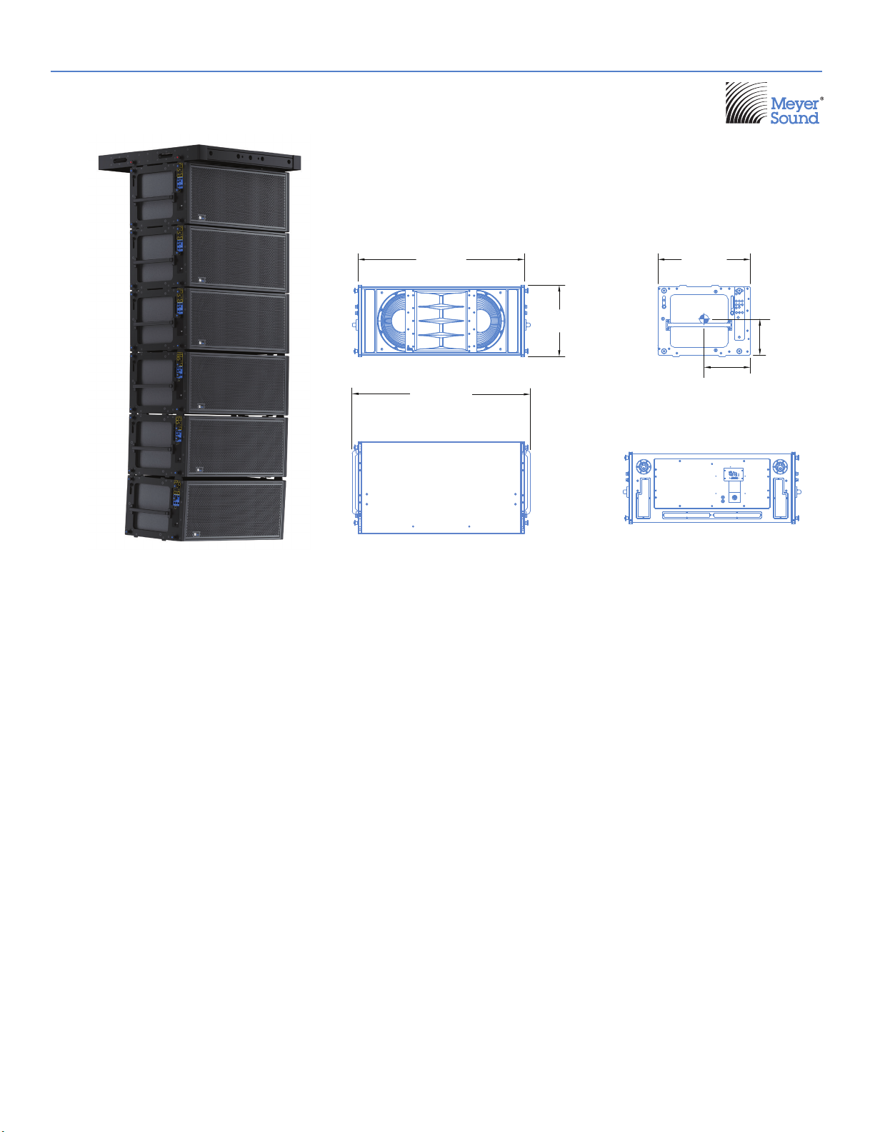
[1052 mm]
[1128 mm]
Sonic linearity at any output level defines the LEO‑M™ advanced
linear array loudspeaker. Conceived for long‑throw applications,
with exceptional headroom, extremely low distortion, and optimized
rigging options, LEO‑M forms the nucleus of Meyer Sound’s
next‑generation LEO® array systems. Pair LEO arrays with
Meyer Sound’s 1100‑LFC low‑frequency control element for
bass reproduction, and the LYON™ linear line array loudspeaker
for downfill. Drive entire systems with Meyer Sound’s Galileo®
GALAXY Network Platform, which provides 24 bit, 96kHz audio,
matrix routing, alignment, and processing for array components.
To guarantee optimum system performance, design LEO array
systems with Meyer Sound’s MAPP™ System Design Tool. This
intuitive, cross‑platform application accurately predicts coverage
patterns, frequency and impulse responses, and linear peak SPL
for LEO array systems, ensuring that systems deliver the required
SPL and ideal coverage for the intended audience areas.
LEO‑M’s high‑frequency section comprises two proprietary
compression drivers coupled to a constant‑directivity horn
through a patented REM® manifold. The manifold’s smooth
radiating characteristics afford tight vertical coverage. The
low‑frequency section includes two long‑excursion cone drivers,
also proprietary, capable of withstanding high continuous
output levels. Precise phase and magnitude alignment between
low‑ and high‑frequency drivers yields consistent and well‑behaved
system responses.
The unit’s power amplifier operates at nominal voltages from
41.42
44.42
17.85
[453 mm]
23.00
[584 mm]
[292 mm]
11.50
9.00
[229 mm]
208—235 V AC at 50—60 Hz. TruPower® limiting ensures
maximum driver protection, minimizing power compression while
yielding high constant output under high continuous and peak
power conditions. A single field‑replaceable module located on
the rear of the cabinet contains the amplifier, control electronics,
and power supply.
Meyer Sound’s RMS™ remote monitoring system comes standard
with all LEO‑M loudspeakers and provides comprehensive
monitoring of system parameters on a Mac® or Windows®‑based
computer. Convenient XLR 5‑pin connectors allow the use of
composite cables carrying both RMS and balanced audio.
LEO‑M offers intuitive rigging with captive GuideALinks™ that
users can set to the desired splay angles while cabinets rest in
caster frames. The MTG‑LEO‑M top grid flies arrays of up to 22
LEO‑Ms at a 5:1 safety factor (with some restrictions). Fly LYONs
below LEO‑M arrays for downfill with available optional transition
frames. Securely transport stacks of up to four LEO‑Ms with the
optional MCF‑LEO‑M caster frame; Protect the cabinets during
transport with optional durable nylon covers that accommodate
stacks of two, three, or four units.
Meyer Sound builds the vented LEO‑M cabinet with premium
multi‑ply birch and coats it with a slightly textured black finish.
A powder‑coated, hex‑stamped steel grille with acoustical black
mesh protects the unit’s drivers. The weather‑protected cabinet and
included collapsible rain hood that shields user panel connectors
from water intrusion accommodate a variety of applications.
Page 2
FEATURES AND BENEFITS
• Optimized line arrays with controlled directivity for even coverage and consistent responses over long throws
• High peak power output with exceptional linearity and transient reproduction at extreme levels
• Self‑powered design for simplified setup and increased reliability
• Optimized rigging that allows splay angles to be set while stacks rest in caster frames
• Seamless integration with LYON line array loudspeakers, and the 1100‑LFC and VLFC low frequency control elements
APPLICATIONS
• Stadiums
• Arenas
• Touring sound reinforcement
• Large‑scale public events
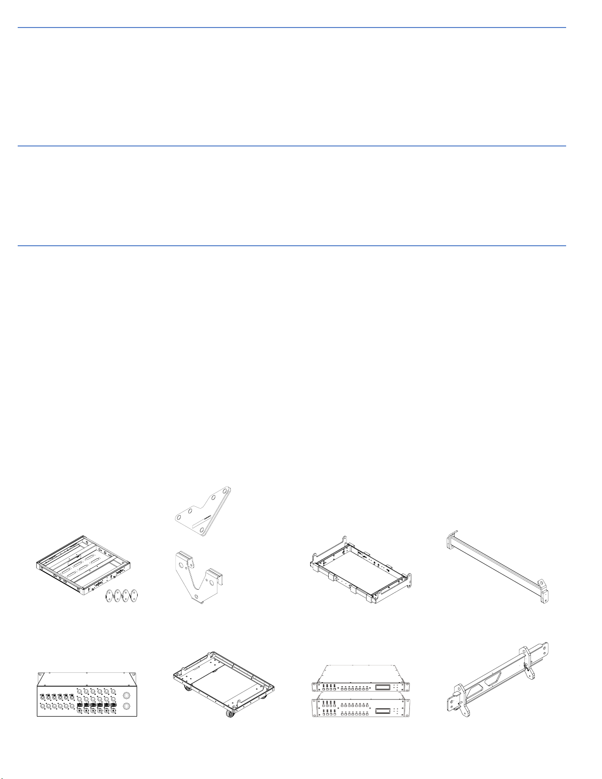
ACCESSORIES AND ASSOCIATED PRODUCTS
MTG‑LEO‑M Top Grid: With some restrictions, flies up to 22 LEO‑Ms at a 5:1 safety factor and BGV C1; accommodates a variety of pickup configurations
with six pickup points; includes attachment points to accommodate brackets and adapters for lasers and inclinometers. Always use MAPP to verify rigging
load ratings. Optional MTG‑LEO Groundstack Grid Link Kit available to enable using the grid as a base by flipping it upside‑down (4 links in kit).
MVP Motor Vee Plate: Attaches to MTG‑LEO‑M (and all other LEO family grids) and fine tunes horizontal aim of LEO arrays.
RPP‑LEO‑M Rear Pull‑up Plate: Helps assemble large arrays with wide splay angles by providing pull‑up (with a motor) to expand the array’s splay angles
during installation, so that it is easier to insert the blue locking pins.
MTF‑LEO‑M/LYON Transition Frame: With some restrictions, flies up to 9 LYONs at a 5:1 safety factor and BGV C1 below LEO‑M arrays for downfill;
includes rear attachment points for pull‑back.
PBF‑LEO‑M Pull‑back Frame: Attaches to the bottom cabinet of LEO‑M arrays and provides pull‑back for extreme array downtilt.
MDM‑5000 Distribution Module: Offers convenient power distribution and flexible routing of audio, AC power, and RMS to loudspeaker arrays.
MCF‑LEO‑M Caster Frame: Safely transports up to four LEO‑M cabinets, making it easy to assemble and disassemble arrays in blocks. Durable nylon
covers for stacks of 2, 3 and 4 units are also available to ensure the LEO‑M is completely road ready.
Galileo GALAXY Network Platform: The Galileo GALAXY Network Platform provides state‑of‑the‑art audio control technology for loudspeaker systems
with multiple zones. With immaculate sonic performance, it provides a powerful tool set for corrective room equalization and creative fine‑tuning for a full
range of applications.
GEB‑LEO Grid Extender Bar: Attaches to the MTG‑LEO Top Grid and by extending the pick‑up points, it provides a few extra degrees of downtilt or uptilt
without requiring extra motors or rigging points when rigging LEO‑M arrays. For more severe downtilt, the pull‑back frame is the best solution.
MTG‑LEO‑M Top Grid and optional
Groundstack Grid Link Kit
MDM‑5000 Power and Signal
Distribution Module
MVP Motor Vee Plate (top)
RPP‑LEO‑M Rear Pull‑up Plate
MCF‑LEO‑M Caster Frame Galileo GALAXY Network Platform GEB‑LEO Grid Extender Bar
MTF‑LEO‑M/LYON Transition
Frame
PBF‑LEO‑M Pull‑back Frame
Page 3

SPECIFICATIONS
ACOUSTICAL
1
COVERAGE
TRANSDUCERS
AUDIO INPUT
Operating Frequency Range255 Hz – 16 kHz
Phase Response 375 Hz – 14 kHz ±30°
Linear Peak SPL3149.5 dB with 20 dB crest factor (M‑noise), 142.5 dB (Pink noise), 144 dB (B‑noise)
Horizontal Coverage 75°
Vertical Coverage Varies, depending on the array length and configuration
Low Frequency Two 15‑inch long‑excursion cone drivers; 4 Ω nominal impedance
High Frequency
Maximum Common Mode Range ±15 V DC, clamped to earth for voltage transient protection
Connectors XLR 5‑pin female input with male loop output
Input Impedance 10 kΩ differential between pins 2 and 3
Nominal Input Sensitivity 0 dBV (1 V rms) continuous is typically the onset of limiting for noise and music
Two 4‑inch diaphragm compression drivers coupled to a constant‑directivity horn through a patented
REM manifold; 12 Ω nominal impedance
Type Differential, electronically balanced
Pin 1: Chassis/earth through 1 kΩ, 1000 pF, 15 V clamped network to provide virtual ground lift at
audio frequencies
Pin 2: Signal +
Pin 3: Signal ‑
Wiring
Pin 4: RMS
Pin 5: RMS
Case: Earth ground and chassis
AMPLIFIERS
AC POWER
CURRENT DRAW
Input Level
Total Output Power49900 W Peak
THD, IM, TIM < 0.02%
Cooling Two ultra high‑speed primary fans, two ultra high‑speed reserve fans
Connector powerCON 32
Automatic Voltage Selection 208–235 V AC, 50–60 Hz
Safety Rated Voltage Range 208–235 V AC, 50–60 Hz
Turn‑on and Turn‑off Points Turn‑on: 165 V AC; Turn‑off: 264 V AC
Idle Current 0.6 A rms (230 V AC)
Max Long‑Term Continuous Current (>10 sec) 6.0 A rms (230 V AC)
Burst Current (<1 sec)58.0 A rms (230 V AC)
Maximum Instantaneous Peak Current 24 A peak (230 V AC)
Inrush Current < 15 A peak
Audio source must be capable of producing of +20 dBV (10 V rms) into 600 Ω to produce the
maximum peak SPL over the operating bandwidth of the loudspeaker
Type 3‑channel complementary MOSFET output stages (class AB/H bridged)
Page 4

SPECIFICATIONS, CONT’D.
RMS NETWORK
Equipped with two‑conductor, twisted‑pair network; reports all amplifier operating parameters to host
computers
PHYSICAL
Dimensions W: 44.42 in (1128 mm) x H: 17.85 in (453 mm) x D: 23.00 in (584 mm)
Weight 265 lb (120.2 kg)
Enclosure Premium multi‑ply birch, slightly textured black finish
Protective Grille Powder coated, hex‑stamped steel with acoustical black mesh
Rigging
End frames with captive GuideALinks secured with 0.5‑inch x 1.125‑inch quick‑release pins that allow
0.5°–5° splay angles; detachable handles
NOTES
1. Loudspeaker system predictions for coverage and SPL are available in Meyer Sound’s MAPP System Design Tool.
2. Recommended maximum operating frequency range. Response depends on loading conditions and room acoustics.
3. Linear Peak SPL is measured in free‑field at 4 m referred to 1 m. Loudspeaker SPL compression measured with M‑noise at the onset of limiting,
2‑hour duration, and 50‑degree C ambient temperature is <2 dB.
M‑noise is a full bandwidth, (10Hz–22.5kHz) test signal developed by Meyer Sound to better measure the loudspeaker’s music performance. It
has a constant instantaneous peak level in octave bands, a crest factor that increases with frequency, and a full bandwidth Peak to RMS ratio of
18 dB.
Pink noise is a full bandwidth test signal with Peak to RMS ratio of 12.5 dB.
B‑noise is a Meyer Sound test signal used to ensure measurements reflect system behavior when reproducing the most common input spectrum,
and to verify there is still headroom over pink noise.
4. Peak power based on the maximum unclipped peak voltage the amplifier will produce into the nominal load impedance.
5. AC power cabling must be of sufficient gauge so that under burst current rms conditions, cable transmission losses do not cause the
loudspeaker’s voltage to drop below the specified operating range.
ARCHITECTURAL SPECIFICATIONS
The loudspeaker shall be a self‑powered, linear, low‑distortion, line
array loudspeaker. Its transducers shall include two 4‑inch diaphragm
compression drivers coupled to a constant‑directivity horn through a
patented REM manifold, and two 15‑inch, long‑excursion cone drivers.
The loudspeaker shall incorporate internal processing and a 3‑channel
class AB/H bridged amplifier with complementary MOSFET output stages.
Protection circuits shall include TruPower limiting. The audio input shall
be electronically balanced with a 10kΩ impedance and accept a nominal
0 dBV (1.0 V rms) signal (+20 dBV to produce maximum peak SPL).
Audio connectors shall be XLR 5‑pin, female and male, accommodating
both balanced audio and RMS. Performance specifications for a typical
production unit shall be as follows, measured at 1/3‑octave resolution:
operating frequency range shall be 55Hz to 16kHz; phase response shall
be 375Hz to 14kHz ±30degrees; linear peak SPL shall be 149.5 dB with
20 dB crest factor, measured free‑field with M‑noise at 4 m referred to 1 m.
Meyer Sound Laboratories, Inc.
2832 San Pablo Avenue
Berkeley, CA 94702
+1 510 486.1166
www.meyersound.com/contact
www.meyersound.com
The internal power supply shall perform EMI filtering, soft current turn‑on,
and surge suppression. Power requirements shall be nominal 230V AC
line current at 50–60 Hz. UL and CE operating voltage range shall be
208–235V AC at 50–60Hz. Current draw during burst (< 1 sec) shall be
8A rms at 230 VAC. Current inrush during soft turn‑on shall not exceed
15A at 230VAC. The AC power connector shall be a powerCON 32. The
loudspeaker shall include an RMS remote monitoring system module.
Components shall be mounted in an optimally tuned, vented enclosure
constructed of premium multi‑ply birch and coated with a slightly textured
black finish. The protective grille shall be powder‑coated, hex‑stamped
steel with acoustical black mesh. Dimensions shall be 44.42 in (1128 mm)
wide x 17.85 in (453mm)high x 23.00 in (584 mm)deep. Weight shall be
265lb(120.2kg).
The loudspeaker shall be the Meyer Sound LEO‑M.
LEO-M
04.215.019.01 B4
Copyright © 2020. All Rights Reserved.
 Loading...