

Page 1
STANDARD COUNTING SCALE OPERATION & SERVICE MANUAL
Model XTC
STANDARD COUNTING SCALE www.mt.com/xpress
Page 2

2
STANDARD COUNTING SCALE
ABOUT THIS MANUAL AND MT EXPRESS
Thank you for purchasing an MT Xpress product.
All of our equipment is assembled and packed with great care. If you should find any incorrect item,
please contact your Xpress Dealer immediately.
This MT Xpress product was developed, produced, and tested in a METTLER TOLEDO facility that has
been audited and registered according to international ISO 9001 quality standards and ISO 14000
environment control program. Properly used and maintained, this product will provide years of accurate
weighing. Handle it as you would any piece of fine electronic equipment.
Please READ this manual BEFORE operating or servicing this equipment. Follow the instructions carefully
and save this manual for future reference.
We at MT Xpress want to make sure you received the product you expected. It is important to us that you
are satisfied with your purchase. If there is anything we can help you with, or if you are not satisfied with
either your product or the services received from the Xpress representative, let us know.
How can you reach us?
XPRESS CUSTOMER CARE CENTER, USA
24/7 Information and Support: www.mt.com/xpress
xpress@mt.com
8 AM to 8 PM EST Toll Free: 1-866-MTXPRESS
Xpress
Mettler-Toledo, Inc.
60 Collegeview
Westerville, OH 43081
Page 3

STANDARD COUNTING SCALE
FCC Approval
This device complies with part 15 of the FCC Rules. Operation is subject to the following two
conditions: (1) this device may not cause harmful interference, and (2) this device must accept any
interference received, including interference that may cause undesired operation.
3
Page 4

4
STANDARD COUNTING SCALE
CONTENTS
SAFTEY NOTICE...................................................................................................................................... 5
PREPARING THE SCALE FOR USE ............................................................................................................. 6
ENVIRONMENT .......................................................................................................................6
UNPACKING AND ASSEMBLY....................................................................................................6
YOUR XPRESS SCALE AT A GLANCE .......................................................................................................... 8
DISPLAY ................................................................................................................................8
KEYPAD.................................................................................................................................8
DISPLAY WINDOWS ................................................................................................................8
CURSORS (VFD) .....................................................................................................................9
OPERATING YOUR SCALE ...................................................................................................................... 10
STRAIGHT COUNTING ............................................................................................................10
PUSH-BUTTON TARE .............................................................................................................10
KEYBOARD TARE ..................................................................................................................11
DECREMENT COUNTING ........................................................................................................12
SPECIAL OPERATION FUNCTIONS ........................................................................................................... 13
ID FUNCTION........................................................................................................................ 13
ACCUMULATION FUNCTION ....................................................................................................14
RECALL AND EXIT THE ACCUMULATOR ....................................................................................14
AVERAGE PIECE WEIGHT (APW) FUNCTION .............................................................................14
COMMUNICATION FUNCTION..................................................................................................15
DATA OUTPUT.......................................................................................................................15
EXTERNAL COMMANDS .........................................................................................................15
RECALL FUNCTION ................................................................................................................16
COUNT TARGET ALARM..........................................................................................................16
PRESET THE TARGET ZONE ....................................................................................................16
APW ENHANCEMENT ............................................................................................................17
SPECIAL MODES – SETUP MODE............................................................................................................ 18
ENTERING THE SETUP MODE .................................................................................................18
FUNCTION OF THE KEYS ........................................................................................................18
DISPLAY ILLUSTRATION .........................................................................................................19
CONFIGURATION...................................................................................................................19
CLEANING AND MAINTAINING YOUR SCALE.............................................................................................. 23
CLEANING AND MAINTENANCE...............................................................................................23
TROUBLESHOOTING ..............................................................................................................23
SERVICING YOUR SCALE ....................................................................................................................... 24
ENTERING SERVICE MODE ..................................................................................................... 24
FUNCTION OF THE KEYS ........................................................................................................24
CONFIGURATION...................................................................................................................25
COMMUNICATION .................................................................................................................28
APPENDIX........................................................................................................................................... 31
SETUP MODE PARAMETER OVERVIEW .....................................................................................31
ERROR MESSAGES................................................................................................................32
SPECIFICATIONS ...................................................................................................................33
GEO VALUE TABLE ................................................................................................................34
PHYSICAL DIMENSIONS ......................................................................................................... 35
Page 5

STANDARD COUNTING SCALE
SAFTEY NOTICE
Product safety is a fundamental concern at MT Xpress. Use common sense and follow the simple
precautions listed below to ensure your safety and to optimize the use and performance of this product.
− Read this manual before operating or servicing this product. Save this manual for future reference.
− Observe safety warnings located throughout this manual.
− Use caution when lifting or moving heavy equipment.
− This product should only be serviced by qualified personnel. Exercise care when moving, testing, or
adjusting this product.
− Disconnect all power to this product before installing, servicing, or cleaning.
5
− Use only MT Xpress parts for repair.
− Observe electrostatic handling precautions for electronic components. Allow at least 30 seconds
after power is disconnected to allow charges to dissipate before servicing any electronic
components.
− Allow the product to adjust to room temperature before connecting the power source.
FAILURE TO FOLLOW THESE PRECAUTIONS COULD RESULT IN DAMAGE TO OR DESTRUCTION OF THE
EQUIPMENT, OR BODILY HARM.
FCC NOTICE
This equipment has been tested and found to comply with the limits of the United States of America FCC
rules for a Class A digital device, pursuant to Part 15 of the FCC Rules. This equipment generates, uses,
and can radiate radio frequency energy and, if not installed and used in accordance with the instruction
in this manual, may cause harmful interference to radio communications. Operation of this equipment in
a residential area is likely to cause harmful interference in which case the user will be required to correct
the interference at his own expense.
Page 6

6
STANDARD COUNTING SCALE
PREPARING THE SCALE FOR USE
The XTC Standard Counting Scale is a high performance industrial counting scale that accurately and
dependably counts parts of all shapes and sizes.
This manual provides not only the detailed information on how to operate the scale, but also useful
messages for service and maintenance.
Please read this manual thoroughly and familiarize yourself with all the safety requirements. All service
procedures must only be performed by authorized personnel.
This chapter gives detailed instructions and important information regarding the successful installation of
the Xpress Standard Counting Scale.
ENVIRONMENT
Before you install the scale, identify the best location for the equipment. The proper environment
enhances its operation and longevity. Keep in mind the following factors, which might have a negative
influence on the scale's operation:
Vibration: Vibration diminishes the scale’s ability to measure accurately. Electrical machinery such as
conveyors and drill presses can cause inaccurate and non-repeatable readings. The scale may also
read inaccurately if it is not leveled properly.
Air currents: Moving air can cause the scale to read wind movement as an additional force and cause
inconsistency in the weighing results.
Friction: A scale cannot measure accurately if an object is rubbing or pressing against the scale
platform.
UNPACKING AND ASSEMBLY
Please inspect the package immediately upon receipt. If the box is damaged, check for internal damage
and file a freight claim with the carrier if necessary. If the container is undamaged, open the box, remove
the scale and place it on a solid, flat surface. Please keep the packing material and shipping insert in
case you need to return the scale to an Xpress representative.
Package contents for all Xpress Standard Counting Scales include:
Product
− XTC Counting Scale
− Pan (only with XTC1001)
− Platter Supports Kit
(only with XTC1001)
− Scale Platter
− Adapter
− Lead seal wire and lead
Documents
− Quick Start Guide
− Installation Instructions
CD-ROM
− Operation & Service Manual
Page 7
STANDARD COUNTING SCALE
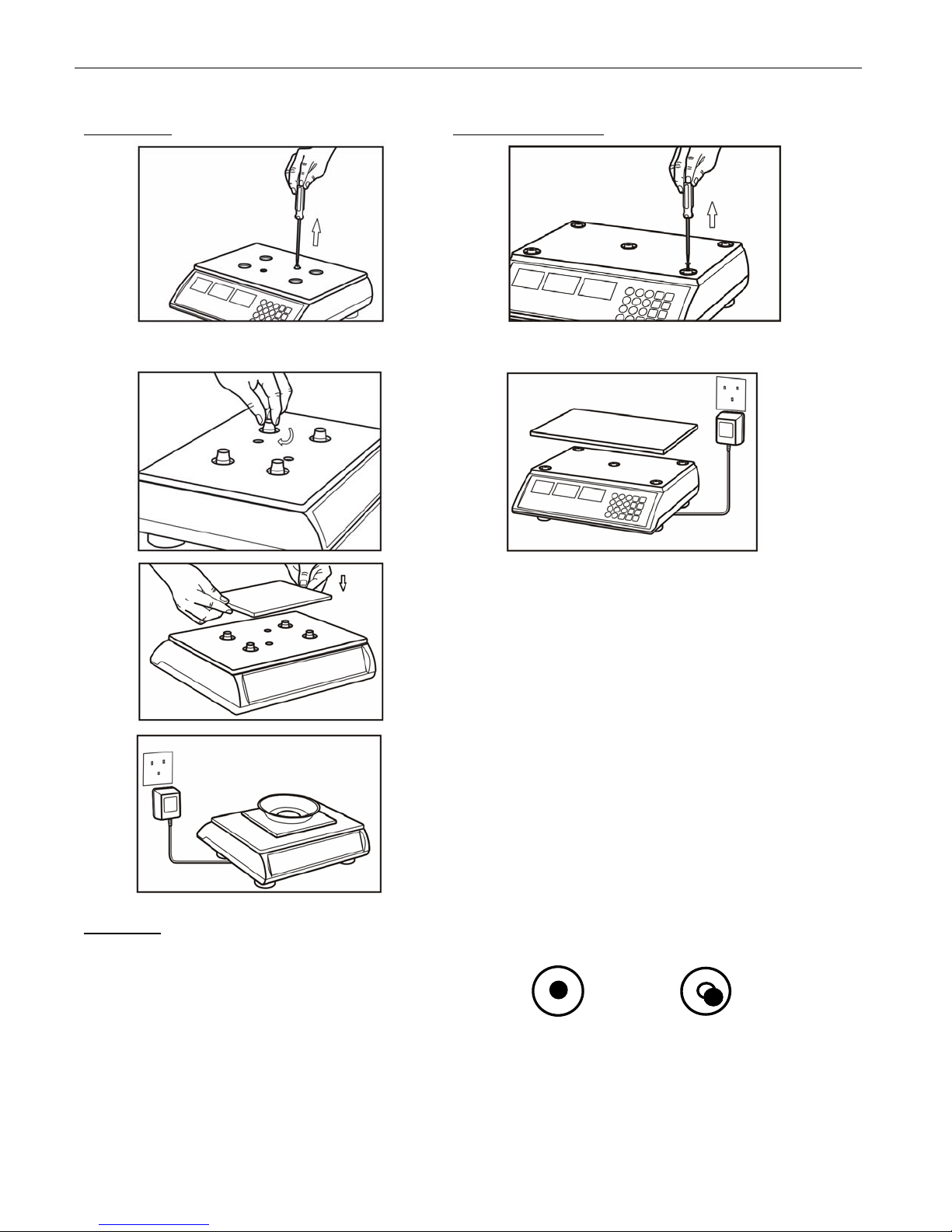
5 lb models 10/20/50 lb models
7
1.
2.
3.
1.
(20/50 lb models skip this step)
2.
4.
All models
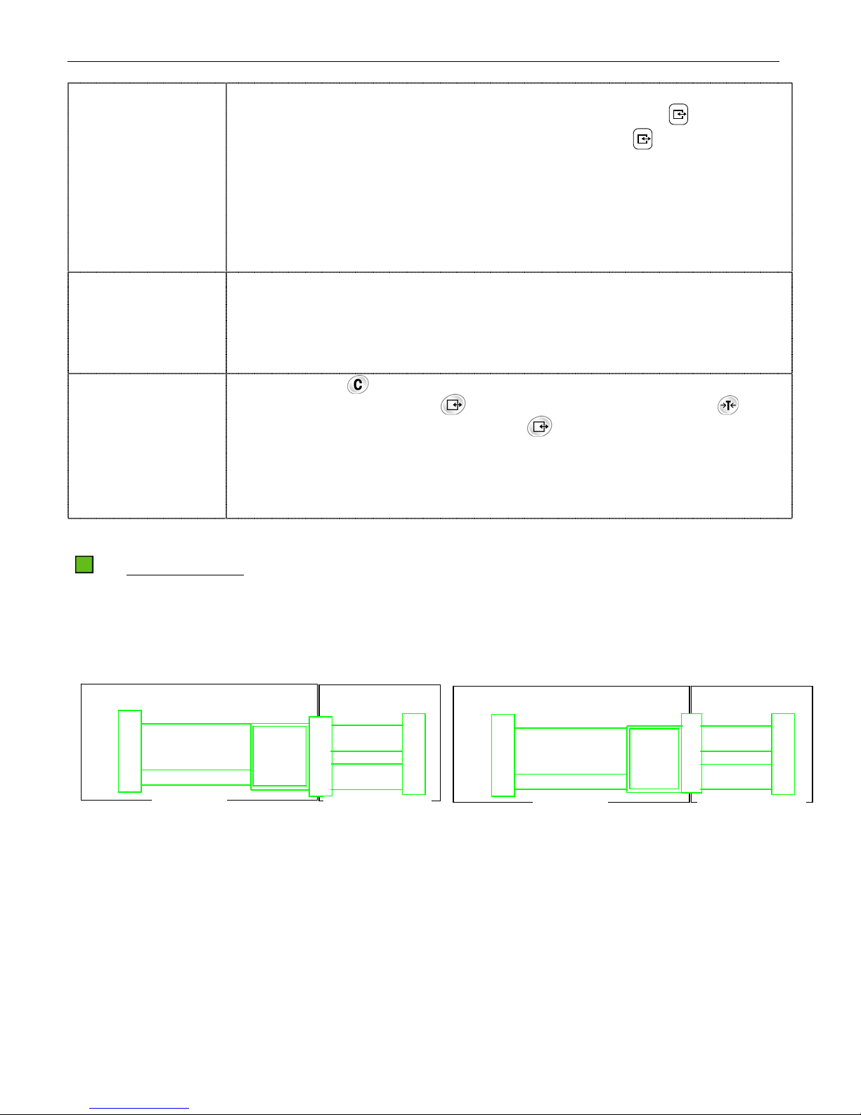
Level the scale by adjusting the four rubber feet
until the leveling bubble is centered in the level
indicator.
Proper alignment Improper alignment
Page 8
8
YOUR XPRESS SCALE AT A GLANCE
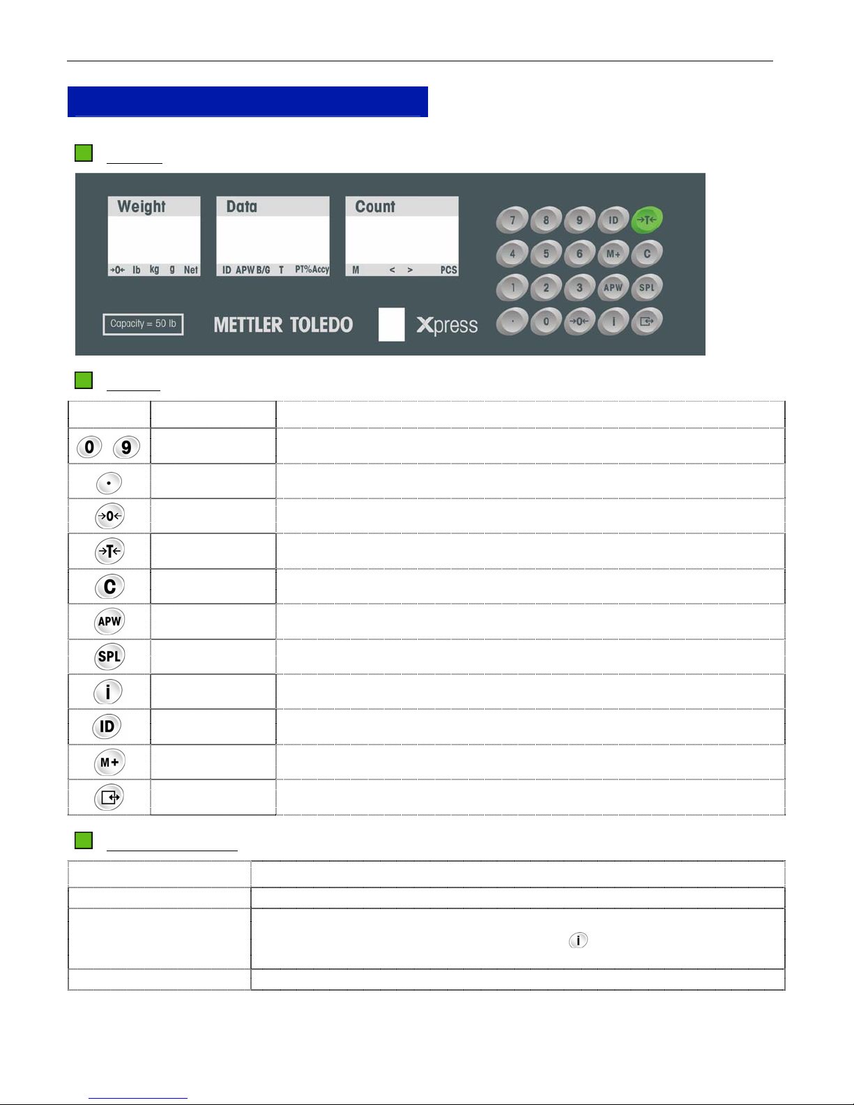
DISPLAY
KEYPAD
Key Name Function
STANDARD COUNTING SCALE
~
Numeric Data entry (0-9)
Decimal Enters a decimal point/Toggles alarm beep
Zero Zeroes the scale
Tare Subtracts tare value and switches from gross to net mode
Clear Clears data from the display
APW Initiates Average Piece Weight (APW) entry
Sample Initiates sampling
Recall Recalls the accumulated quantity and times
ID Store ID number, APW, tare and item number
Accumulation Adds the accumulator counts or recalls accumulation
Enter/Print Confirms an operation or initiates data output
DISPLAY WINDOWS
Window Description
Weight Display (Weight) Displays the weight.
Data Display (Data) Displays item number, APW, gross weight, tare, push-button tare or accuracy
percentage sequentially with each time the key is pressed. The default
display is APW.
Count Display (Count) Displays the counts.
Page 9

STANDARD COUNTING SCALE
CURSORS (VFD)
Key Description
9
→0←
When the scale is at the gross zero, this cursor will be lit
lb, kg, g Weight unit cursor; Weight unit can be set in Setup Mode
Net When net weight is displayed, this cursor will be lit
ID When item number is recalled, this cursor will be lit
APW When Average Piece Weight (APW) is recalled, this cursor will be lit
B/G When gross weight is recalled, this cursor will be lit
T When push-button tare weight is recalled, this cursor will be lit
PT When keyboard tare is recalled, this cursor will be lit
%Accy When the counting accuracy percentage is recalled, this cursor will be lit
M When the value in the accumulator is not zero, this cursor will be lit
PCS When the count is displayed, this cursor will be lit
> Target Alarm: Indicates the count is above the Over value
< Target Alarm: Indicates the count is below the Under value
< > When both > and < cursors are lit, it indicates that the count is within the target zone
Page 10
10
OPERATING YOUR SCALE
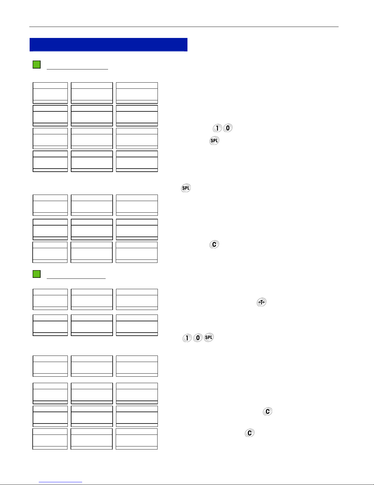
STRAIGHT COUNTING
Weight Data Count
00 0 0 0
u u u
>0< lb kg g Net CN APW B/G T PT
Weight Data Count
00 2 0 0
u u
>0< lb kg g Net CN APW B/G T PT
Weight Data Count
00 2 0 1 0
u
>0< lb kg g Net CN APW B/G T PT
Weight Data Count
00 2 0 00 0 2 0 0 1 0
u u u
>0< lb kg g Net CN APW B/G T PT
Weight Data Count
30 0 0 00 0 2 0 0 1 5 0 0
u u u
>0< lb kg g Net CN APW B/G T PT
Weight Data Count
00 0 0 00 0 2 0 0 0
u u u u
>0< lb kg g Net CN APW B/G T PT
Weight Data Count
00 0 0 0
u u u
>0< lb kg g Net CN APW B/G T PT
M < > PCS
M < > PCS
M < > PCS
M < > PCS
M < > PCS
M < > PCS
M < > PCS
STANDARD COUNTING SCALE
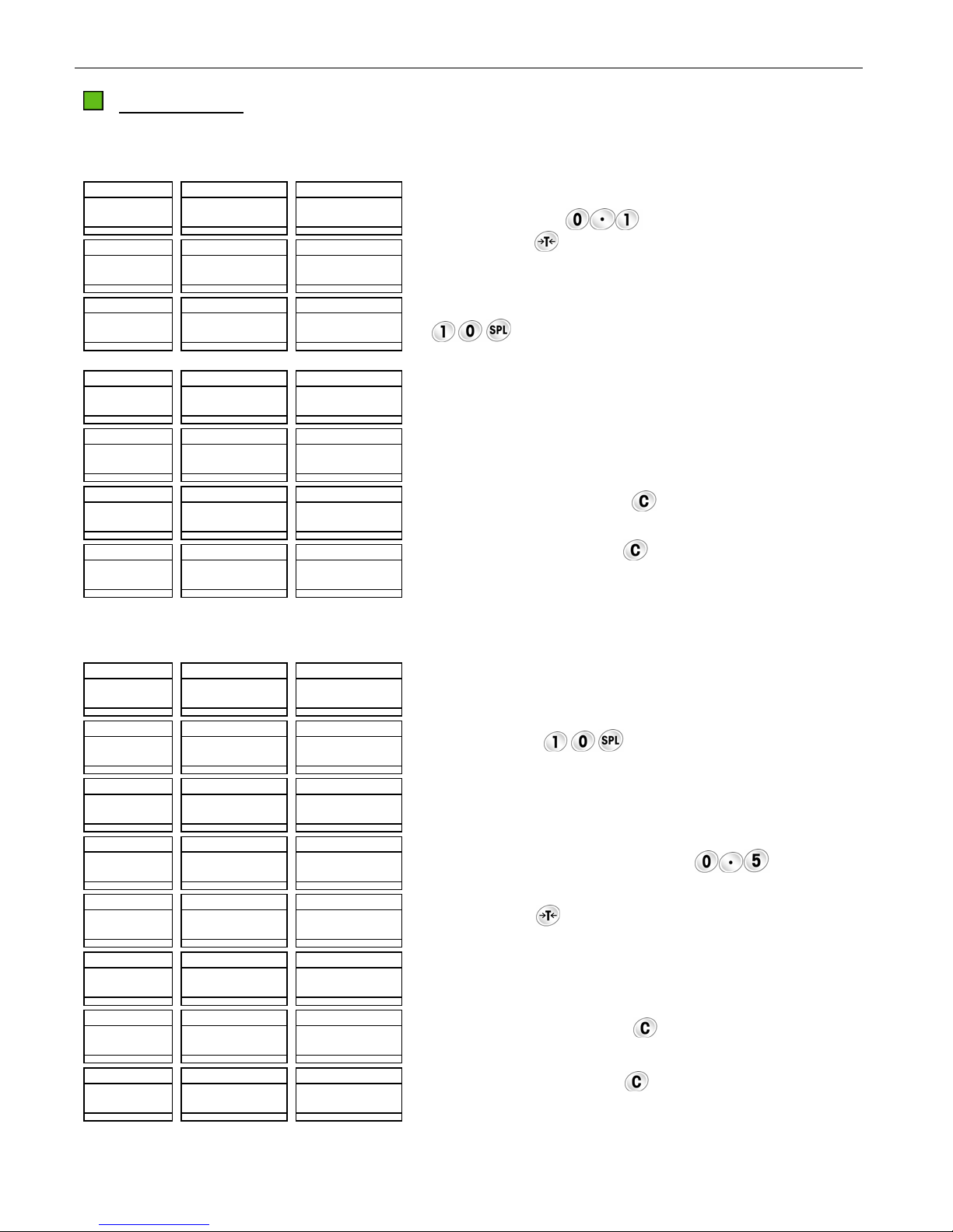
The XTC counting scale is in the weight mode and ready for
counting operation.
Place the samples on the platter (e.g. 10 pieces, total weight
is 0.020 lb).
Press the keys
to input the sample pieces.
Press the key to initiate Average Piece Weight (APW).
Note: If the sample weight is less than the minimum sample
weight set in the Setup Mode, the count window will show
“ADD XX” indicating that “XX” more pieces should be added
on the platter. After adding the required quantity, press the
key to re-sample.
Place the items to be counted on the platter (e.g. 1500
pieces including samples).
Remove all the items from the platter.
Press the key to clear the APW.
PUSH-BUTTON TARE
Weight Data Count
00 0 0 0
u u u
>0< lb kg g Net CN APW B/G T PT
Weight Data Count
00 2 0 00 0 2 0 0 1 0
u u u u
>0< lb kg g Net CN APW B/G T PT
Weight Data Count
30 0 0 00 0 2 0 0 1 5 0 0
u u u u
>0< lb kg g Net CN APW B/G T PT
Weight Data Count
- 02 0 0 00 0 2 0 0 1 0 0
u u u u
>0< lb kg g Net CN APW B/G T PT
Weight Data Count
- 02 0 0 0
u u u
>0< lb kg g Net CN APW B/G T PT
Weight Data Count
00 0 0 0
u u u
>0< lb kg g Net CN APW B/G T PT
M < > PCS
M < > PCS
M < > PCS
M < > PCS
M < > PCS
M < > PCS
Place the empty container or wrapping material on the platter
(e.g., 0.2 lb), and then press .
Place the samples in the container or on the wrapping
material and then onto the platter (e.g. 10 pieces, total
weight is 0.02 lb). Initiate APW by pressing the
keys
.
Place the items to be counted in the container or on the
wrapping material and then onto the platter (e.g. 1500
pieces including samples).
Remove all the items from the platter.
Clear the APW data by pressing .
Clear the tare by pressing again.
Page 11
STANDARD COUNTING SCALE
3
5
3
5
KEYBOARD TARE
There are two operation procedures for this function.
Operation Procedure 1
Weight Data Count
00 0 0 01
u u u
>0< lb kg g Net CN APW B/G T PT
Weight Data Count
- 01 0 0 0
u u u
>0< lb kg g Net CN APW B/G T PT
M < > PCS
M < > PCS
Weight Data Count
00 2 0 00 0 2 0 0 1 0
u u u u
>0< lb kg g Net CN APW B/G T PT
M < > PCS
Weight Data Count
30 0 0 00 0 2 0 0 1 5 0 0
u u u u
>0< lb kg g Net CN APW B/G T PT
M < > PCS
Weight Data Count
- 01 0 0 00 0 2 0 0 5 0
u u u u
>0< lb kg g Net CN APW B/G T PT
M < > PCS
Weight Data Count
- 01 0 0 0
u u u
>0< lb kg g Net CN APW B/G T PT
M < > PCS
Weight Data Count
00 0 0 0
u u u
>0< lb kg g Net CN APW B/G T PT
M < > PCS
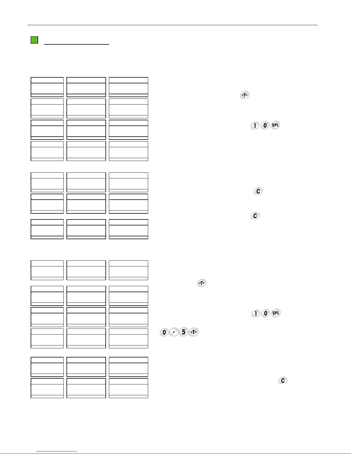
Press the appropriate keys for the known tare value (e.g. 0.1
lb, press the keys to input tare value 0.1).
Press the key to initiate the input value as tare.
Place the samples in the container or on the wrapping
material and then onto the platter (e.g. 10 pieces, total
weight is 0.02 lb). Initiate APW by pressing the keys
Place the items to be counted in the container or on the
wrapping material and then onto the platter (e.g. 1500
pieces including samples).
Remove all the items and the container or wrapping material
from the platter.
Clear the APW by pressing .
Clear the tare by pressing again.
11
.
Operation Procedure 2
Weight Data Count
00 2 0 0
u u
>0< lb kg g Net CN APW B/G T PT
Weight Data Count
00 2 0 00 0 2 0 0 1 0
u u u
>0< lb kg g Net CN APW B/G T PT
Weight Data Count
0 0 00 0 2 0 0 1 7 5 0
u u u
>0< lb kg g Net CN APW B/G T PT
Weight Data Count
0 0 05
u
>0< lb kg g Net CN APW B/G T PT
Weight Data Count
30 0 0 00 0 2 0 0 1 5 0 0
u u u u
>0< lb kg g Net CN APW B/G T PT
Weight Data Count
- 05 0 0 00 0 2 0 0 2 5 0
u u u u
>0< lb kg g Net CN APW B/G T PT
Weight Data Count
- 05 0 0 0
u u u
>0< lb kg g Net CN APW B/G T PT
Weight Data Count
00 0 0 0
u u u
>0< lb kg g Net CN APW B/G T PT
M < > PCS
M < > PCS
M < > PCS
M < > PCS
M < > PCS
M < > PCS
M < > PCS
M < > PCS
Place the samples on the platter (e.g. 10 pieces, total
weight is 0.02 lb).
Press the keys
to initiate APW.
Place the items to be counted in the container or on
the wrapping material and then onto the platter, (e.g.
1500 pieces including samples).
Input the data by pressing the keys
.
Press the key
to initiate the tare as 0.5lb.
Remove all the items and the container or wrapping
material from platter.
Clear the APW by pressing
.
Clear the tare by pressing again.
Page 12
12
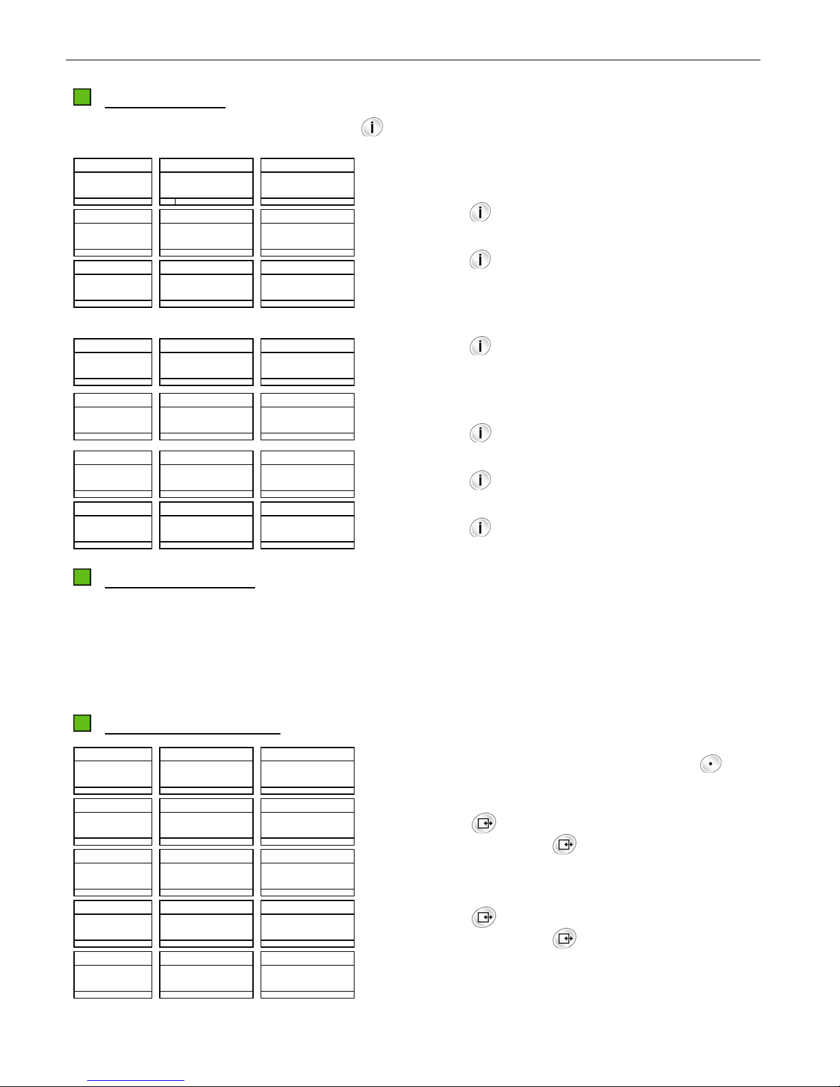
DECREMENT COUNTING
There are two decrement counting modes.
Mode 1
Weight Data Count
00 0 0 0
u u u
>0< lb kg g Net CN APW B/G T PT
M < > PCS
Weight Data Count
- 00 2 0 0
u u u
>0< lb kg g Net CN APW B/G T PT
M < > PCS
Weight Data Count
- 00 2 0 00 0 2 0 0 1 0
u u u u
>0< lb kg g Net CN APW B/G T PT
M < > PCS
Weight Data Count
- 20 0 0 00 0 2 0 0 1 0 0 0
u u u u
>0< lb kg g Net CN APW B/G T PT
M < > PCS
Weight Data Count
- 30 0 0 00 0 2 0 0 1 5 0 0
u u u u
>0< lb kg g Net CN APW B/G T PT
M < > PCS
Weight Data Count
- 30 0 0 0
u u u
>0< lb kg g Net CN APW B/G T PT
M < > PCS
Weight Data Count
00 0 0 0
u u u
>0< lb kg g Net CN APW B/G T PT
M < > PCS
Mode 2
Weight Data Count
00 0 0 0
u u u
>0< lb kg g Net CN APW B/G T PT
Weight Data Count
- 00 2 0 0
u u u
>0< lb kg g Net CN APW B/G T PT
Weight Data Count
- 00 2 0 00 0 2 0 0 1 0
u u u u
>0< lb kg g Net CN APW B/G T PT
Weight Data Count
29 8 0 00 0 2 0 0 1 4 9 0
u u u u
>0< lb kg g Net CN APW B/G T PT
Weight Data Count
- 05 0 0 00 0 2 0 0 2 5 0
u u u u
>0< lb kg g Net CN APW B/G T PT
Weight Data Count
00 0 0 0
u u u
>0< lb kg g Net CN APW B/G T PT
M < > PCS
M < > PCS
M < > PCS
M < > PCS
M < > PCS
M < > PCS
STANDARD COUNTING SCALE
Place the items to be counted in the container or on the
wrapping material and then onto the platter (e.g. 3 lb
including tare). Press the key .
Remove the samples from the platter (e.g. 10 pieces, total
weight is 0.02 lb).
Initiate APW by pressing the keys .
Remove all the items from the container or the wrapping
material (e.g. 1000 pieces including the samples). The
count stands for the pieces removed from the platter
including the sample.
Remove the container or wrapping material from the platter.
Clear the APW by pressing the key .
Clear the tare by pressing the key again.
Place the items in the container or on the wrapping material
and then onto the platter (e.g. 3.5 lb including tare), then
press the key
.
Remove the samples from the platter (e.g. 10 pieces, total
weight is 0.02 lb).
Initiate APW by pressing the keys .
Input the known tare (e.g. 0.5 lb) by pressing the keys
. The count stands for the pieces in the
container or on the wrapping material, not including the
samples already removed.
Remove all the items and the container or wrapping material
from the platter.
Clear the APW and tare by pressing the key
twice.
Page 13
STANDARD COUNTING SCALE
A
SPECIAL OPERATION FUNCTIONS
ID FUNCTION
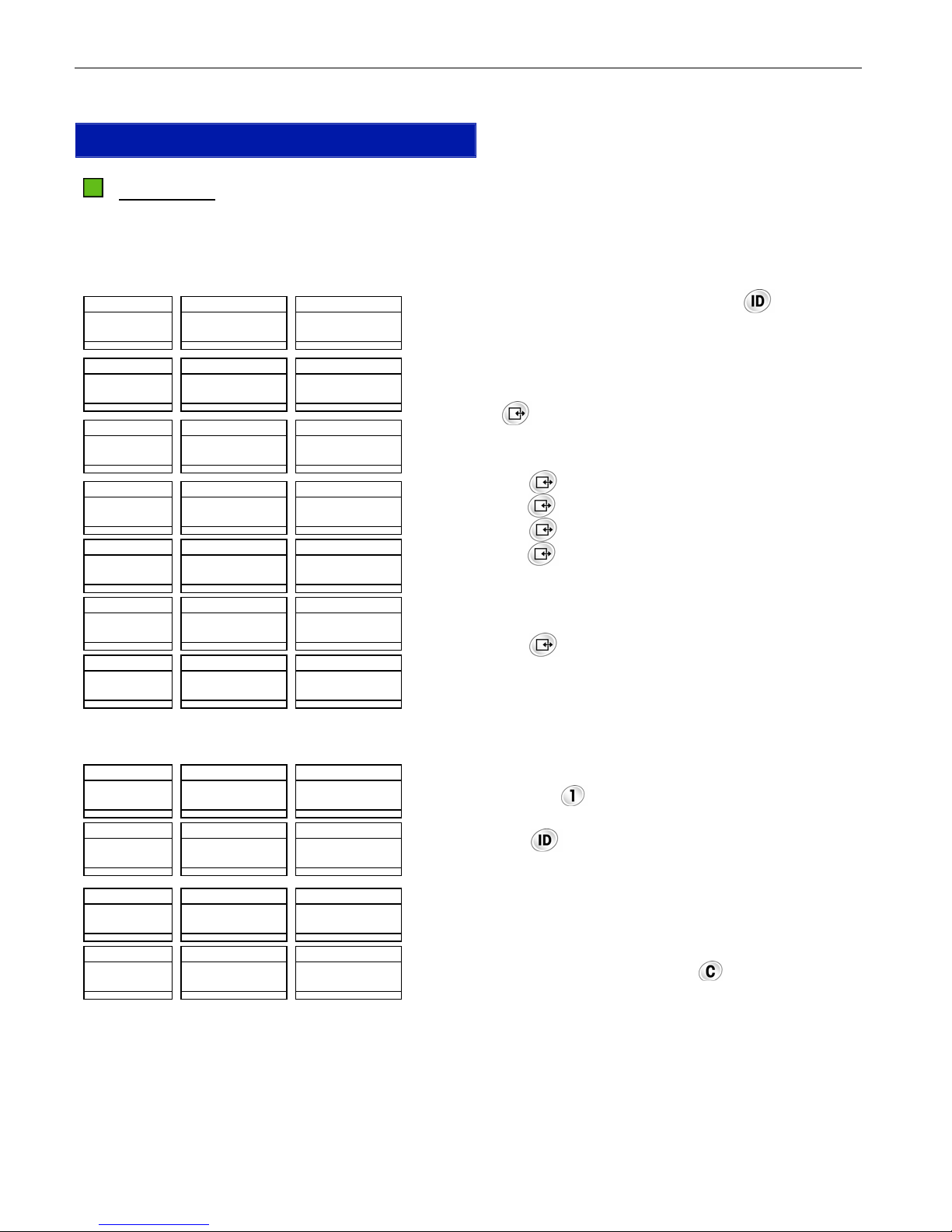
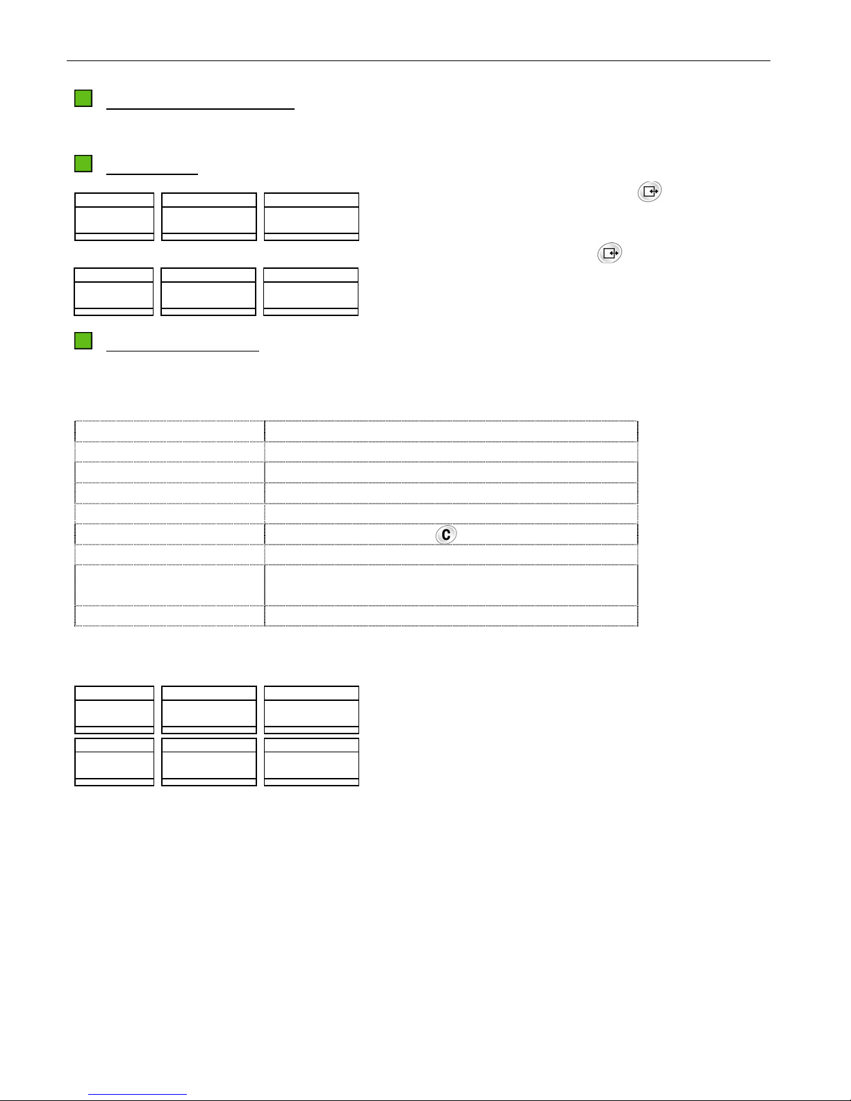
20 ID can be stored with 2-digit ID No. and APW and 6-digit item No. and tare. ID data will not be lost
when power is off. Emptying the item No. can clear an ID. The tare stored in the ID is keyboard tare.
Store an ID
Weight Data Count
I d ?
>0< lb kg g Net ID APW B/G T PT %Accy
Weight Data Count
I d ?
>0< lb kg g Net ID APW B/G T PT %Accy
Weight Data Count
P U ? 00 0 0 0 0
>0< lb kg g Net ID APW B/G T PT %Accy
Weight Data Count
M < > PCS
M < > PCS
M < > PCS
t A r E ? 00 0 0
>0< lb kg g Net ID APW B/G T PT %Accy
Weight Data Count
M < > PCS
I t n o ? 0
>0< lb kg g Net ID APW B/G T PT %Accy
Weight Data Count
M < > PCS
I t n o ? 7 8 9 0 1 2
>0< lb kg g Net ID APW B/G T PT %Accy
Weight Data Count
00 0 0 0 0
u u u
>0< lb kg g Net ID APW B/G T PT %Accy
M < > PCS
M < > PCS
In the count or weight mode, press the key to enter the
ID entry mode.
Enter a numeric value 1 (acceptable from 1 to 20).
Press key
to display the existing APW (if this ID has
existed) or current APW (if this ID is a new one) to
waiting new APW input.
Press the key
directly or input the known APW then
press the key to wait for new tare input.
Press the key directly or input the known tare then
press the key to wait for the item No. input.
Input the item No. up to 6 digits (e.g. 789012)
Press the key to accept the input and return the scale
the previous mode.
Recall an ID
Weight Data Count
0 00 0 0 1
>0< lb kg g Net ID APW B/G T PT %Accy
Weight Data Count
-
00 2 0 00 0 2 0 0 1 0
u u u u
>0< lb kg g Net ID APW B/G T PT %Accy
Weight Data Count
n o I d
>0< lb kg g Net ID APW B/G T PT %Accy
Weight Data Count
00 0 0 0
u u u
>0< lb kg g Net ID APW B/G T PT %Accy
0
u
M < > PCS
M < > PCS
M < > PCS
M < > PCS
In count or weight mode, press the desired numeric
key (e.g.: the key
) to input ID No. (e.g. ID No.
is 1).
Press the key to recall the desired ID (e.g.: ID1),
the data in ID1 will be recalled from the memory,
while active the accumulator with the same No.
If no ID, the Weight window shows “no id” for 2
seconds, then back to previous mode.
After finishing all transactions, press
key to clear
ID and active accumulator 0.
Note: the recalled APW or tare can be modified
temporarily.
13
Page 14
14
y
y
STANDARD COUNTING SCALE
ACCUMULATION FUNCTION
There are 21 accumulators to store the total counts. The data in the accumulator will be lost when power
to the scale is lost.
Weight Data Count
30 0 0 00 0 2 0 0 1 5 0 0
u u u u
>0< lb kg g Net CN APW B/G T PT %Acc
M < > PCS
Weight Data Count
00 0 0 0
u u u u
>0< lb kg g Net CN APW B/G T PT %Accy
M < > PCS
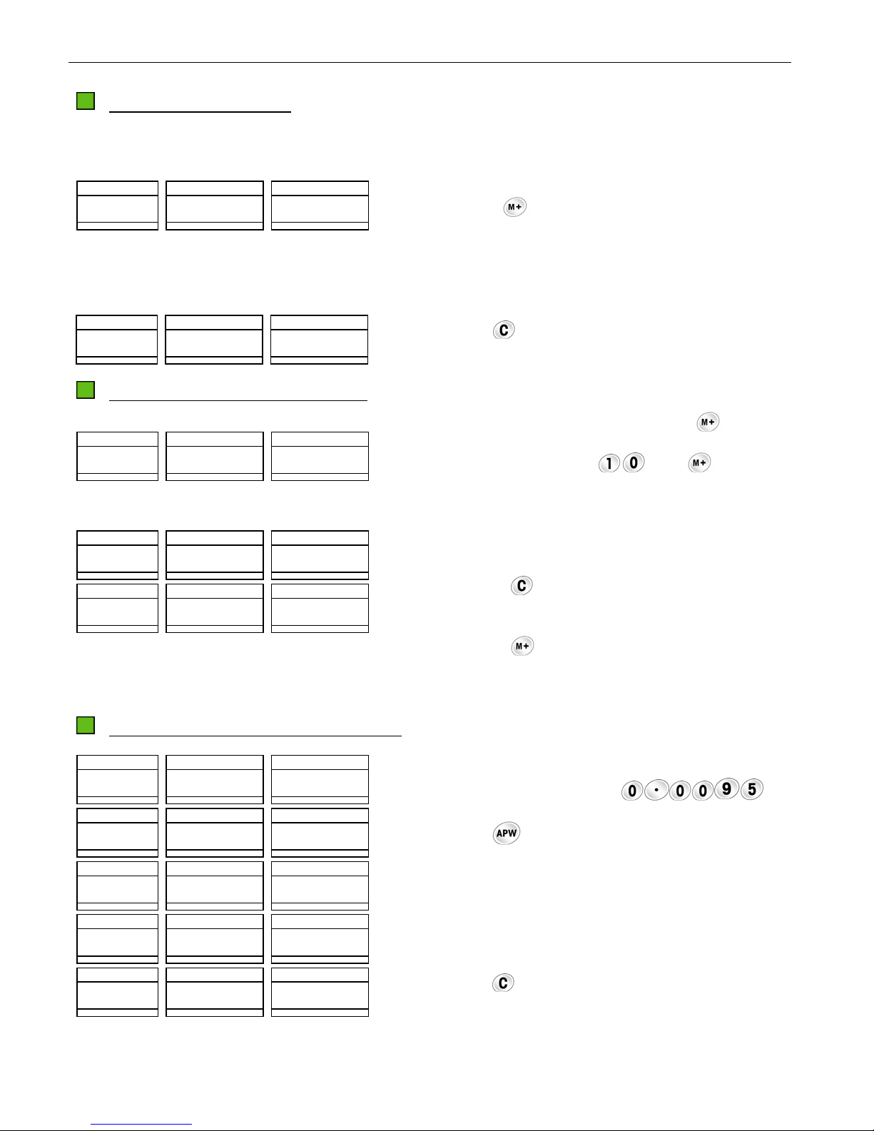
When the scale is in the count mode and the count is not
zero, press the key. The beeper will give a double beep
to indicate the displayed counts have been added into the
accumulator and the “M” cursor will be lit.
Repeat above steps until all transactions are accumulated.
Note: The weight should return to zero before the next
accumulation.
Press the key
to clear the APW.
RECALL AND EXIT THE ACCUMULATOR
Weight Data Count
t O t A L C n 2 3 2 5 0
>0< lb kg g Net CN APW B/G T PT %Acc
u
M < > PCS
Weight Data Count
00 0 0 0
u u u
>0< lb kg g Net CN APW B/G T PT %Accy
M < > PCS
Weight Data Count
00 0 0 0
u u u u
>0< lb kg g Net CN APW B/G T PT %Accy
M < > PCS
AVERAGE PIECE WEIGHT (APW) FUNCTION
Weight Data Count
00 0 0 00 0 9 5
u u
>0< lb kg g Net CN APW B/G T PT %Accy
Weight Data Count
00 0 0 00 0 9 5 0 0
u u u u
>0< lb kg g Net CN APW B/G T PT %Accy
Weight Data Count
09 5 0 00 0 9 5 0 1 0 0
u u u
>0< lb kg g Net CN APW B/G T PT %Accy
Weight Data Count
00 0 0 00 0 9 5 0 0
u u u u
>0< lb kg g Net CN APW B/G T PT %Accy
Weight Data Count
00 0 0 0
u u u
>0< lb kg g Net CN APW B/G T PT %Accy
M < > PCS
M < > PCS
M < > PCS
M < > PCS
M < > PCS
In weight mode, press the key Press the key
to recall the
accumulated count in the temporary accumulator.
Press the numeric keys (e.g.: ) and to recall the
accumulated count in the corresponding accumulator (e.g.:
accumulator 10).
In accumulation display mode, there are two ways to return
the scale to the previous mode.
Pressing the key to clear the accumulator and return the
scale back to the previous mode.
Pressing the key to return the scale back to the previous
mode without clearing the accumulator.
In the count and weight mode, enter the APW data (e.g.
0.0095 lb) by pressing the keys .
Press the key
to initiate APW.
Place the items to be counted on the platter.
Remove all the items from the platter.
Press the key to clear the APW.
Page 15
STANDARD COUNTING SCALE
COMMUNICATION FUNCTION
With the optional RS-232 cable kit, the XTC can communicate to a printer or a PC.
DATA OUTPUT
15
Weight Data Count
t o t A L C n 3 4 5 0 0
>0< lb kg g Net CN APW B/G T PT %Accy
Weight Data Count
- 00 2 0 00 0 2 0 0 1 0
u u u u
>0< lb kg g Net CN APW B/G T PT %Accy
u
M < > PCS
M < > PCS
In accumulation display mode, press to print the total
counts and CN or transmit the data to a PC.
In count or weight mode, press
to print the APW, tare,
pieces, and/or gross weight (The items depend on the soft
switch setting in the Setup Mode.) or transmit the data to
a PC.
EXTERNAL COMMANDS
The XTC can accept some ASCII coded commands from a host PC. The commands are identified as
follows:
Keys Description
[T][Enter] Equal to push-button tare operation
[Z][ Enter] Equal to zero operation
[P][ Enter] Equal to print operation
[C][ Enter] Equal to clearing operation
[C][C][ Enter] Equal to pressing the key twice
[T][XXXXXX][Enter] Initiate XXXXXX as the tare
[S][XXXXXX][Enter] Initiate an APW. XXXXXX is the sample pieces and the
weight on the platter is the sample weight
[A][XXXXXXXX][Enter] Initiate XXXXXXXX as the APW
For example:
Weight Data Count
09 5 0 00 0 9 5 0 1 0 0
u u u
>0< lb kg g Net CN APW B/G T PT %Accy
Weight Data Count
00 0 0 00 0 9 5 0 0
u u u u
>0< lb kg g Net CN APW B/G T PT %Accy
M < > PCS
M < > PCS
The scale is in the count mode.
Press the keys [T][Enter] on the keyboard of a PC. The XTC
will accept this command and tare the scale.
Page 16
16
3
5
y
y
y
y
y
y
A
RECALL FUNCTION
STANDARD COUNTING SCALE
The XTC can subtract some data via the key
Weight Data Count
30 0 0 00 0 2 0 0 1 5 0 0
u u u u
>0< lb kg g Net CN APW B/G T PT %Accy
Weight Data Count
30 0 0
u u u u
>0< lb kg g Net CN APW B/G T PT %Accy
0 0 0 1 5 0 0
Weight Data Count
30 0 0 05 00 0 1 5 0 0
u u u u
>0< lb kg g Net CN APW B/G T PT %Accy
Weight Data Count
30 0 0 00 00 0 1 5 0 0
u u u u
>0< lb kg g Net CN APW B/G T PT %Accy
Weight Data Count
30 0 0 9 99 5 1 5 0 0
u u u u
>0< lb kg g Net ID APW B/G T PT %Acc
Weight Data Count
30 0 0 8 1 5 0 0
u u u u
>0< lb kg g Net CN APW B/G T PT %Accy
Weight Data Count
30 0 0 00 0 2 0 0 1 5 0 0
u u u u
>0< lb kg g Net CN APW B/G T PT %Accy
M < > PCS
M < > PCS
M < > PCS
M < > PCS
M < > PCS
M < > PCS
M < > PCS
. The default data is APW when the scale powers up.
The scale is in the count or weight mode. (Weight window
shows the weight value.)
Press the key . The B/G cursor will light and the Data
window will display gross weight (e.g. 3.5 lb).
Press the key and the T cursor will light. If the current tare
is a push-button tare, the Data display will show the tare
value. If the tare is a keyboard tare or no tare exists, it will
be 0.0000.
Press the key and the PT cursor will light. The Data
display will show the tare that was input via the keyboard. If
the tare is a push-button tare or no tare exists, it will show
0.0000.
Press the key , the %Accy cursor is lit, the Data display
will show the counting accuracy percentage.
Press the key , the ID cursor is lit, the Data display will
show the value of the item No..
Press the key and the APW cursor will light. The Data
display will show the APW.
COUNT TARGET ALARM
A target zone (>/<) can be preset via keyboard. If the target alarm is enabled in the Setup Mode, the
scale will beep continually when the piece count is within or outside of this range depending on the soft
switch setting. If the target zone has been preset, the under cursor “< “ will be lit when the piece count is
below the Under value. When the piece count is above the Over value, the over cursor “>“ will be lit. If
both, the Over and Under values are 0, the target alarm will be disabled.
PRESET THE TARGET ZONE
Weight Data Count
u n d E r ? 1 2 0 0
>0< lb kg g Net CN APW B/G T PT %Acc
Weight Data Count
M < > PCS
u n d E r ? 1 8 0 0
>0< lb kg g Net CN APW B/G T PT %Acc
Weight Data Count
M < > PCS
O U E r ? 1 2 5 0
>0< lb kg g Net CN APW B/G T PT %Acc
Weight Data Count
M < > PCS
O U E r ? 1 8 3 0
>0< lb kg g Net CN APW B/G T PT %Acc
Weight Data Count
30 0 0 00 0 2 0 0 1 5 0 0
u u u u u
>0< lb kg g Net CN APW B/G T PT %Acc
Note: Both Over and Under values equal to 0 will disable the Target Alarm function.
M < > PCS
M < > PCS
u u
u u
u u
u u
In count or weight mode, press and hold the key
for
about three seconds, then release the key. The scale will
enter into target zone setting mode.
Press the key to accept the displayed value, or enter a
new value and then press
to accept it.
fter entering the Under value, the display will show prompts
as the illustrated.
Press the key
new value and then press
to accept the displayed value, or enter a
to accept it.
After entering the Over value, the scale will return to the
previous mode automatically.
Page 17

STANDARD COUNTING SCALE
17
APW ENHANCEMENT
APW enhancement improves the accuracy of an APW. APW enhancement is based on the fact that an
inaccurate APW, while not able to accurately count large numbers of parts, will reliably count a small
number. This allows a determination of APW based on a larger weight. Given enough enhancements,
the APW becomes very accurate.
This function permits the operator to continuously update the APW based on larger and larger samples.
As additional pieces are placed on the scale, a new APW can be calculated based on the new total
sample weight and count.
The APW can be enhanced constantly up to 4% of the scale capacity. To ensure a minimum APW initial
accuracy, a sample weight of at least five display increments must be used. There is a selection in setup
mode which increases the minimum sample to 0.015%, 0.1% or 0.2% of capacity.
When using APW enhancement, you must not add more pieces to the scale than what can be counted
accurately using the current APW (about the same pieces, which have already been counted). If this
maximum is exceeded, a warning of [OVER] will be displayed for approximately two seconds then will
automatically clear. The operator can remove parts until [OVER] will not be displayed again.
If the operator ignores the [OVER] display and adds more pieces (or removes more in count-out sample
mode), no further APW enhancement will be done for the current transaction. If the proper procedure is
followed, the scale will continue to enhance the APW until 4% of the scale capacity is reached. Once the
counting weight reaches 4%, APW enhancement is discontinued.
Notice: The APW inputted via keyboard or recalled from an ID can not be enhanced.
Page 18
18
STANDARD COUNTING SCALE
SPECIAL MODES – SETUP MODE
ENTERING THE SETUP MODE
The operating parameters can be configured in the Setup Mode. When “Full Operator Access” is enabled
in the Service Mode, step S3.1, the Setup Mode can be accessed by pressing and holding the key
for about seven seconds and then releasing the key.
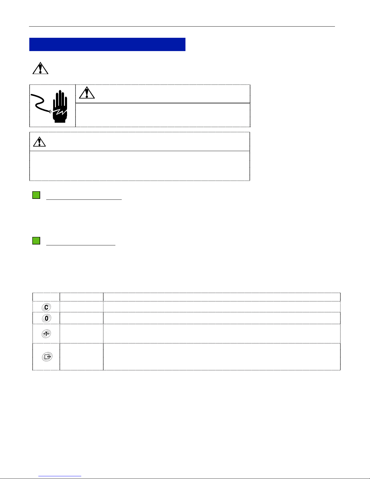
FUNCTION OF THE KEYS
After Setup Mode is accessed, use the four keys, FINISH, BACKUP, TOGGLE and ACCEPT, to configure the
parameters.
In the Setup Mode, the functions of the keys will be as follows:
Key Function Description
Finish
Used to end scale configuration and proceed to End Block.
Backup
Toggle
Used to step back through program blocks and sub-blocks.
Used to step through the blocks. Once a block is accessed, this key is used to
toggle settings On and Off or to step through the setting options of the sub-block.
Used to access the program block or to accept the displayed option. Once a
Accept
displayed sub-block option is accepted, the scale will step forward to the next
sub-block or block.
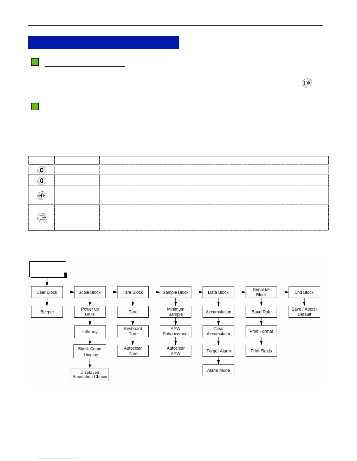
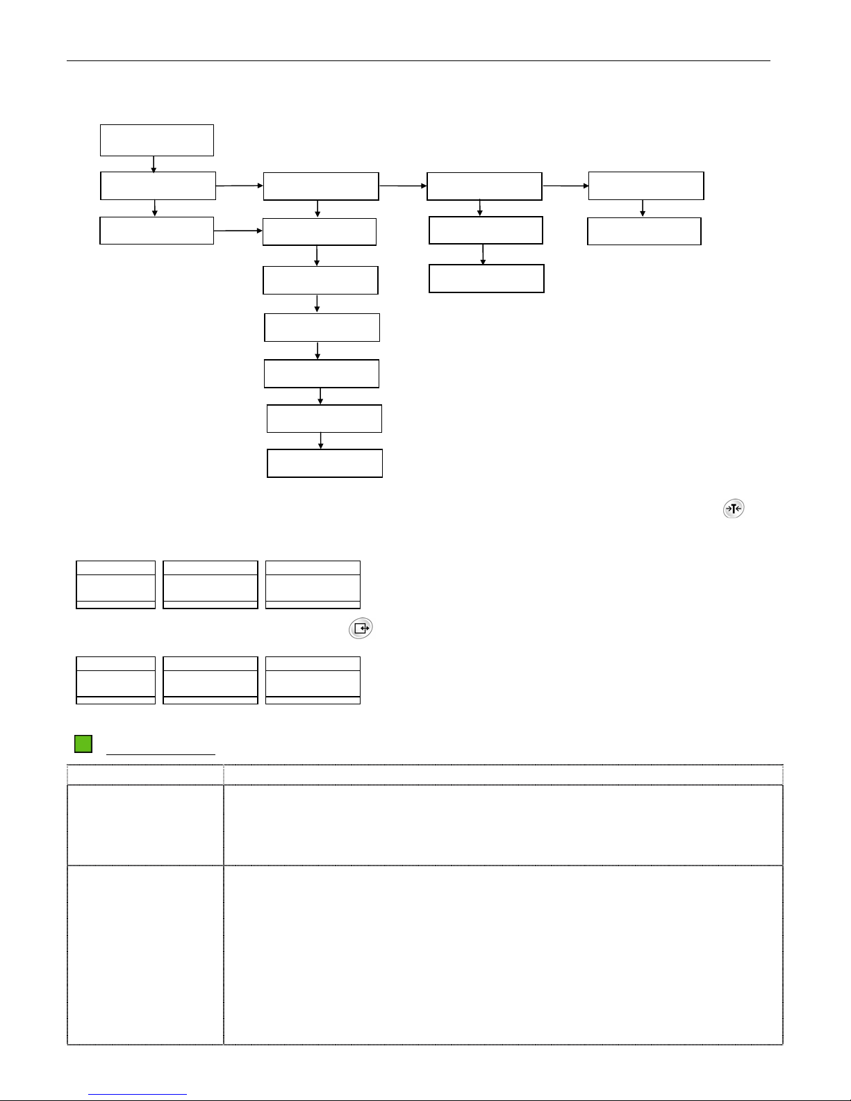
The following diagram gives an overview of the program blocks and sub-blocks.
Setup Mode
Page 19
STANDARD COUNTING SCALE
g
g
19
DISPLAY ILLUSTRATION
The scale automatically moves to the first block as soon as the master mode is accessed. Press the key
to toggle among blocks [SCALE], [tArE], [SAMPLE], [dAtA], [SEriAL], [id] and [End]. When a block
is displayed, press the key to access the first sub-block or to go to end block.
Setup Mode Sample Display—Major block Setup Mode Sample Display—Sub-block
Weight Data Count
F 1 u S E r
>0< lb kg g Net CN APW B/G T PT
M < > PCS
Weight Data Count
F11 oFF
>0< lb k
Net CN APW B/G T PT
M < > PCS
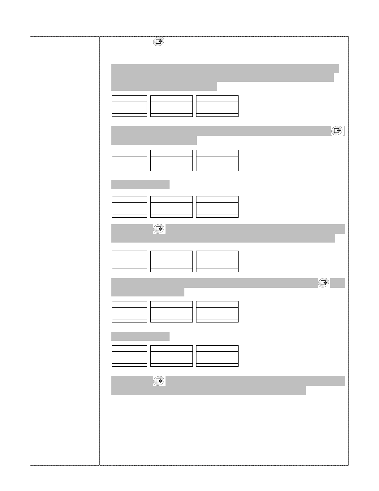
CONFIGURATION
Blocks Sub Blocks/Parameters
F1 User Block F1.1 Beeper
Off = Disable beeper
On = Enable beeper
F2 Scale Block
F2.1 Power-up Weight Units
1 = kg
2 = lb
3 = g
The cursor corresponding to the selected unit should be “on” during this block.
F2.3 Digital Filter
0 = No filtering
1 = Light filtering
2 = Heavy filtering
F2.4 Blank Count Blank
Off = The count display will show whatever residual count is existing based on
the scale internal divisions and the APW entered, regardless of the weight
displayed.
On = When the weight display (gross and net) is reading zero, the count
display will be zero.
F2.5 Displayed Resolution Choice
0 = 5 lb/0.002 lb, 10 lb/0.005 lb, 20 lb/0.01 lb, 50 lb/0.02 lb
1 = 5 lb/0.001 lb, 10 lb/0.002 lb, 20 lb/0.005 lb, 50 lb/0.01 lb
2 = 5 lb/0.0005 lb, 10 lb/0.001 lb, 20 lb/0.002 lb, 50 lb/0.005 lb
3 = 5 lb/0.0002 lb, 10 lb prohibit, 20 lb/0.001 lb, 50 lb/0.002 lb
F3 Tare Block
F3.1 Tare
Off = Disable tare
On = Enable tare
F3.2 Keyboard Tare
Off = Disable keyboard tare
On = Enable keyboard tare
Page 20

20
F3.3 Auto Clear Tare
Off =Disable auto clear tare
On = Enable auto clear tare
Automatic clear of tare occurs when net weight exceeds 9d. It settles to no
motion and then returns to within +/-3d from gross zero.
F4 Sample Block F4.1 Minimum Sample
Off = No minimum sample weight is required. The APW will “flash”, if the
sample weight is below 0.05% of the capacity until the weight used to
calculate the new APW due to APW enhancement goes above 0.05%.
0.05 = Minimum sample is 0.05% of capacity. If the sample weight is below
this minimum sample weight, the count display will show “add XX” to require
additional samples and data display will blank out to indicate APW
calculation is forbidden until the sample weight is more than 0.05% of
capacity and the new APW is calculated.
0.10 = Minimum sample is 0.10% of the capacity.
0.20 = Minimum sample is 0.20% of the capacity.
F4.2 Average Piece Weight (APW) Enhancement
Off = Disable APW enhancement
On = Enable APW enhancement
F4.3 Auto Clear APW
Off = Disable automatic clear of APW
On = Enable automatic clear of APW
Automatic clear of APW occurs when gross weight (or net weight if a tare has
been taken) exceeds 9d, settles to no motion, and then returns to within +/3d from gross zero.
F5 Data Block
F5.1 Accumulation
Off = Disable accumulation
On = Enable accumulation
F5.2 Clear Accumulator after Print
Off = Disable clear after print
On = Enable clear after print
F5.3 Target Alarm
Off = Disable target alarm
On = Enable target alarm
F5.4 Alarm Mode
Off = Scale beeps continuously when count is within the target range
On = Scale beeps continuously when count is out of target range
F5.5 Alarm Type
Off = Weight alarm
On = Quantity alarm
F6 Serial Interface F6.1 Baud Rate
STANDARD COUNTING SCALE
Page 21

STANDARD COUNTING SCALE
Block
300 = 300 baud
1200 = 1200 baud
2400 = 2400 baud
4800 = 4800 baud
9600 = 9600 baud
F6.2 Print Line Format
Off = Multiple line format
On = Single line format
F6.3 Print ID
Off = Disable printing of ID
On = Enable printing of ID
F6.4 Print Gross
Off = Disable printing of gross weight
On = Enable printing of gross weight
F6.5 Print Tare
Off = Disable printing of tare
On = Enable printing of tare
F6.6 Print Net
Off = Disable printing of net weight
On = Enable printing of net weight
F6.7 Print Average Piece Weight (APW)
Off = Disable printing of APW
On = Enable printing of APW
F6.8 Print Pieces
Off = Disable printing of pieces
On = Enable printing of pieces
F6.9 Print Item No.
Off = Disable printing of Item No.
On = Enable printing of field Item No.
F6.10 Output
0 = Command output
1 = Stable output
F7 ID Block F7.1 ID
21
Page 22

22
Off = Disable ID
On = Enable ID
F7.2 Auto Clear ID
Off = Disable auto clear ID
On = Enable auto clear ID
End Block
This block is used to exit the Setup Mode. After exiting the Setup Mode, the scale
will self-test automatically and enter into weight mode.
Save = Save all the changes and exit Setup Mode.
Abort = Abort any changes and exit Setup Mode.
Default = Reset all parameters to the factory defaults and exit the Setup Mode.
STANDARD COUNTING SCALE
Page 23
STANDARD COUNTING SCALE
CLEANING AND MAINTAINING YOUR SCALE
WARNING
DISCONNECT ALL POWER TO THIS UNIT
BEFORE INSTALLING, SERVICING,
CLEANING, OR REMOVING THE FUSE.
FAILURE TO DO SO COULD RESULT IN
BODILY HARM AND/OR PROPERTY
DAMAGE.
CLEANING AND MAINTENANCE
− DO NOT allow untrained personnel to operate, clean, inspect, maintain, service, or tamper with this
equipment.
− DO NOT attempt to remove the cover or to perform service/maintenance on the internal parts of the
scale.
23
− ALWAYS DISCONNECT this equipment from the power source before cleaning or performing
maintenance.
− KEEP the scale clean. Periodically clean the keyboard and cover with a soft clean cloth that has
been dampened with a mild window cleaner or detergent. DO NOT USE ANY TYPE OF INDUSTRIAL
SOLVENT OR CHEMICALS. DO NOT SPRAY CLEANER DIRECTLY ONTO THE UNIT.
− DO NOT put the scale under water. Use a damp cloth to clean the scale.
TROUBLESHOOTING
If operational difficulties are encountered, first obtain as much information as possible regarding the
problem. Failures and malfunctions can often be traced to simple causes such as loose connections or
improper setup.
Additional troubleshooting can be performed by your authorized Xpress Service representative.
Page 24
24
SERVICING YOUR SCALE
For the following services, please contact your Xpress representative at www.mt.com/xpress.
WARNING
DISCONNECT ALL POWER TO THIS UNIT BEFORE INSTALLING, SERVICING,
CLEANING, OR REMOVING THE FUSE. FAILURE TO DO SO COULD RESULT IN
BODILY HARM AND/OR PROPERTY DAMAGE.
CAUTION
BEFORE CONNECTING OR DISCONNECTING ANY INTERNAL ELECTRONIC COMPONENTS OR
INTERCONNECTING WIRING BETWEEN ELECTRONIC EQUIPMENT, ALWAYS REMOVE POWER AND
WAIT AT LEAST THIRTY (30) SECONDS. FAILURE TO OBSERVE THESE PRECAUTIONS COULD
RESULT IN DAMAGE TO OR DESTRUCTION OF THE EQUIPMENT, OR BODILY HARM.
ENTERING SERVICE MODE
STANDARD COUNTING SCALE
1: Remove the calibration plate on the bottom right side of the scale.
2: Slide the set up switch backward to back side, the weight and data displays will show “S1” and “tESt”
respectively.
FUNCTION OF THE KEYS
After the Service Mode is accessed, use the four keys, FINISH, BACKUP, TOGGLE, and ACCEPT, to
configure the parameters.
In the Service Mode, the functions of the keys will be as follows:
Key Function Description
Finish
Back
Toggle
Used to end scale configuration and proceed to End Block.
Used to step back through program blocks and sub-blocks.
Used to step through the blocks. Once a block is accessed, this key is used to
toggle settings on and off or step through the setting options of the sub-block.
Used to access the program block or accept the displayed option. Once a
Accept
displayed sub-block option is accepted, the scale will step forward to the next
sub-block or block.
Page 25
STANDARD COUNTING SCALE
25
The following diagram gives an overview of the program blocks and sub-blocks.
Service Mode
Test Block
Calibration Block
Control Block
End Block
Expended Weight
CAL Units
Operator Access
Save/Abort
GEO Code
Country
Capacity
Increment
Linearity
Calibration
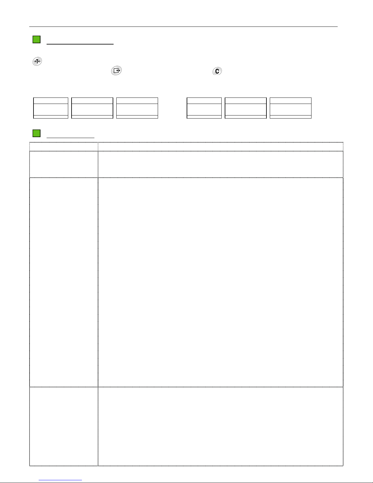
Once the Service Mode is accessed, the scale directly prompts to the first block. Press the key to
toggle among blocks [tESt], [CALIbr], [COntrL] and [End].Service Mode sample display - Test block
Weight Data Count
S 1 t E S t
>0< lb kg g Net ID APW B/G T PT %Accy
M < > PCS
When a block is displayed, press the key key to access the first sub- block.
Weight Data Count
S 11 o F F
>0< lb kg g Net ID APW B/G T PT %Accy
M < > PCS
CONFIGURATION
Blocks Sub Blocks / Parameters
S1 Test Block S1.1 Expanded Mode
Off = Normal weight mode
On = Expanded mode, the display division is 100000
S2 Calibration
Block
In this block you can configure the parameters related to calibration and calibrate
the TC.
S2.1 Calibration Unit
1 = kg
2 = lb
The weight unit cursor under the weight display window will indicate the unit being
selected.
Page 26

26
y
y
y
y
STANDARD COUNTING SCALE
S2.2 GEO Code
GEO. = xx
Select the GEO code according to your location. Please refer to Appendix for
your local GEO code. The scale has been calibrated at the factory. In most
cases, the scale doesn't have to be recalibrated. If the scale is found out of
tolerance after GEO code adjustment, perform the calibration.
S2.3 Capacity
Choose the capacity in accordance with the model.
lb - 5, 10, 20, 50
S2.4 Increment
Display the increment.
5 lb/0.0005 lb, 10 lb/0.001 lb, 20 lb/0.002 lb, 50 lb/0.005 lb
S2.5 Linearity
No = Normal Calibration
YES = Linearity Calibration
S2.6 Calibration
No = Skip Calibration
YES = Perform Calibration
Chose “Yes” to begin calibration and directly enter the first step “Empty Scale”.
The calibration procedure is as follows (take 5lb scale as example):
STEP 1 Empty scale.
Weight Data Count
S 26 E SCL
>0< lb kg g Net ID APW B/G T PT %Acc
M<>PCS
Remove all the items from the platter.
STEP 2 Capture zero
Press the key , the scale will start capturing zero and counting down from 5
to 0.
Weight Data Count
S 26 5
>0< lb kg g Net ID APW B/G T PT %Acc
M<>PCS
STEP 3 Add weight
The display reads as follows. Apply more than 2/3 capacity test weights on the
platter.
Weight Data Count
S 26 0
>0< lb kg g Net ID APW B/G T PT %Acc
M<>PCS
STEP 4 Input the weight data via keyboard
Input the weight data which to be weighted on the platter:
Weight Data Count
S 26 5
>0< lb kg g Net ID APW B/G T PT %Acc
M<>PCS
Page 27
STANDARD COUNTING SCALE
y
y
y
y
y
y
Press the key , the scale will start capturing span and counting down from
5 to 0. Then scale will automatically step forward to the next block.
If “yes” in S2.5 is chosen, the scale needs two points for calibrating the scale.
The procedure to add weight will be as follows (take 5lb scale as example):
After capturing the zero, it will show:
Weight Data Count
S 26 ADD HALF
>0< lb kg g Net ID APW B/G T PT %Acc
M<>PCS
Apply test weight (35%FS~65%FS) on the platter and then press the key .
The display reads as follows:
Weight Data Count
S 26 0HALF
>0< lb kg g Net ID APW B/G T PT %Acc
M<>PCS
Input a weight data.
Weight Data Count
S 26 2 half
>0< lb kg g Net ID APW B/G T PT %Acc
M<>PCS
Press the key , the scale will start capturing span and counting down from
5 to 0. Then scale will automatically step forward to the next step and show:
Weight Data Count
S 26 ADD FULL
>0< lb kg g Net ID APW B/G T PT %Acc
M<>PCS
Apply test weight (>85%FS) on the platter and then press the key . The
display reads as follows:
Weight Data Count
S 26 0 FULL
>0< lb kg g Net ID APW B/G T PT %Acc
M<>PCS
Input a weight data.
Weight Data Count
S 26 5 full
>0< lb kg g Net ID APW B/G T PT %Acc
M<>PCS
Press the key , the scale will start capturing span and counting down from
5 to 0. Then scale will automatically step forward to the next block
Note: If no calibration is done, the changes on the calibration weight and
capacity will be ignored.
27
Page 28
28
STANDARD COUNTING SCALE
S3 Control Block S3.1 Operator Access to Master Mode
Off = No access is allowed to Setup Mode by pressing the key .
On = Full access is allowed to Setup Mode when the key is pressed and
held for about 7 seconds Enable tare
S3.2 Country
2 = Export version
3 = China version
End Block
This block is used to save or abort the changed parameters, and then exit the
Service Mode
Save = Save all the changes and exit Service Mode.
Abort = Exit Service Mode without saving any changes
Exit Service Mode Pressing the key in Service Mode will lead to the end block.
In the end block, press the key
to enter the sub-block. Press the key to
toggle between save or abort. Press the key to accept the choice and exit the
Service Mode. Then the Weight window and Data window will display “SEtuP” and
“OFF” message respectively. Slide the calibration switch back to the normal
position, then the scale will go through a power-up sequence and enter into weight
mode.
COMMUNICATION
The XTC support bi-directional RS-232 serial communication. Using the optional cable with RS-232
convert circuit, the XTC can communicate with a printer or host like PC.
Serial port wiring diagram
DB-9 Female DB-9 Male DB-9 Female
5
2
GND
TXD
RXD
Optional Cable
MIROPCB
RS-232
5
1
3
2
TTL Cable Inside Scale
1
3
4
5
DB-25 Female
7
2
Optional Cable
GND
TXD
RXD
DB-9 Male DB-9 Female
5
MIROPCB
RS-232
1
3
2
TTL Cable Inside Scale
Communication parameter format
Baud rate: 300, 1200, 2400, 4800 and 9600 can be selected via softswitch setting.
Data: 11 bits ASCII codes, among these, there is 1 start bit, 7 ASCII coded data bits, 1 even parity bit
and 2 stop bits.
Data Output Format
There are two data output formats are available: single line output and multi-line output. It can also be
selected to disable output of some data.
1
3
4
5
Page 29
STANDARD COUNTING SCALE
Single Line Output
Format
29
The following is the outputted contents and the related format.
CN: Add one after each printing operation.
STX X X X SP SP
Item No.
X X X X X X SP I T E M SP N o . SP
Gross weight
X X X X X X SP l b SP
Tare weight
X X X X X X SP l b SP T R SP
Net weight
X X X X X X SP l b SP N E T SP
Average piece weight (APW)
X X X X X X X SP l b SP A P W SP
Pieces
X X X X X X SP P C S CR LF
Note:
• [STX] Document Head, ASCII Code 02H.
Multi-line Output
Format
• [SP] Space Bar, ASCII Code 20H.
• [CR] Enter Key, ASCII Code 0DH.
• [LF] Line Feed, ASCII Code 0AH.
• The actual weight unit printed depends on the softswitch setting of
Power-up Weight Unit.
The meaning of the same characters in the following charts will not be illustrated.
CN: Add one after each printing operation.
STX X X X CR LF
Item No.
STX X X X X X X SP I T E M SP N o . CR LF
Gross weight
X X X X X X SP l b CR LF
Tare weight
X X X X X X SP l b SP T R CR LF
Net weight
X X X X X X SP l b SP N E T CR LF
Page 30
30
STANDARD COUNTING SCALE
Average piece weight
X X X X X X X SP l b SP A P W CR LF
Pieces
X X X X X X SP P C S CR LF
Notice: The actual weight unit printed depends on the softswitch setting of Powerup Weight Unit.
When the weight unit is g, the APW should be:
X X X X X X X X X X SP k g SP A P W CR LF
Accumulation Output
Format
STX C N SP X X X SP SP
I T E M SP N o . SP X X X X X X SP SP
T O T SP P C S SP X X X X X X CR LF
External Control Input
External ASCII coded commands input are acceptable to complete the Tare, Zero, Clear, Print and
Sampling operations. The commands are detailed as below.
[T][CR] Push-button tare
[Z][CR] Zero Command
[P][CR] Print Command
[C][CR] Clear APW, if APW is not zero, clear tare if APW is zero.
[C][C][CR] Clear Command. Clear the APW, then clear tare.
[T][XXXXXX][CR] Enter tare. XXXXXX is the value of tare. The last digit of the tare entered should
agree
with the scale divisions. Otherwise, it shall be invalid.
[S][XXXXXX][CR] Enter the number of pieces (XXXXXX) as the sample count.
[A][XXXXXXXX][CR] Enter the value XXXXXXXX as the APW.
Page 31

STANDARD COUNTING SCALE
APPENDIX
SETUP MODE PARAMETER OVERVIEW
Block Soft Switch Description Default
F1 User Block
F1.1 Beeper ON
F2 Scale Block
F2.1 Power-up Weight Unit 2
F2.3 Digital Filter 1
F2.4 Blank Count Display ON
F2.5 Displayed Resolution Choice 2
F3 Tare Block
F3.1 Tare ON
F3.2 Keyboard Tare ON
F3.3 Auto Clear Tare OFF
F4 Sample Block
F4.1 Minimum Sample 0.20
F4.2 APW Enhancement OFF
F4.3 Auto Clear APW OFF
F5 Data Block
F5.1 Accumulation ON
F5.2 Clear Accumulation after Print OFF
F5.3 Target Alarm ON
F5.4 Alarm Mode OFF
F5.5 Alarm Type ON
F6 Serial Interface Block
F6.1 Baud Rate 9600
F6.2 Print Line Format OFF
F6.3 Print CN ON
F6.4 Print Gross ON
F6.5 Print Tare ON
F6.6 Print Net ON
F6.7 Print APW ON
F6.8 Print Pieces ON
F6.9 Print Item No. ON
F6.10 Output 0
F7 ID Block
F7.1 ID ON
F7.2 Auto Clear ID OFF
F7 End Block
End Save/Abort SAVE
31
Page 32

32
STANDARD COUNTING SCALE
ERROR MESSAGES
The scale will display an error message if a problem or an incorrect keyboard entry is sensed. The error
codes are:
Display Possible Cause Troubleshooting
E11 RAM error 1. Restart the scale.
2. Recalibrate the scale.
3. Change the main PCB.
E16 ROM checksum error 1. Restart the scale.
2. Recalibrate the scale.
3. Change the main PCB.
E18 EPROM checksum error 1. Restart the scale.
2. Recalibrate the scale.
3. Change the main PCB.
uuuuu Under capacity 1. Put the scale pan on.
→
←
0
to zero scale.
nnnnn Count data or total counts
are above 999,999, the
2. Press the key
Remove the items until error message disappears or
clear the accumulator.
weight on the platter is 5d
above the full capacity.
------ Cannot capture zero 1. Restart the scale with no weight.
2. Recalibrate the scale.
3. Change the load cell or main PCB.
Page 33

STANDARD COUNTING SCALE
SPECIFICATIONS
33
Display
3 part display (5 digit Weight, 6 digit Data, 6 digit
Count)
12 mm height, green VFD
Internal Resolution
1/500,000
Displayed Resolution
Default: 1/10’000
Maximum: 1/25’000
Keyboard
20 membrane keyboard
Platter
5 lb model: 6.6” x 7.7” Stainless Steel
10/20/50 lb models: 9.5” x 13.5” Stainless Steel
Scale Dimensions
13.6” (L) x 13.6” (W) x 4.8” (H)
Specifications are subject to change without notice.
Units
lb, kg, g
Interface
RS232 (Accessory)
Power
External adapter 12V/600mA
Recommended APW
>1/5d (0.2d)
APW Enhanced
Operating Temperature
32°F to 104°F (0°C to +40°C)
10 to 90% humidity, non-condensing
Page 34

34
STANDARD COUNTING SCALE
GEO VALUE TABLE
Use the following geo codes if you relocate your scale to a site other than the original location where it
was calibrated.
Northern
and
Southern
latitude
in
degrees and minutes
0° 0′ —5° 46′
5° 46′ — 9° 52′
9° 52′ — 12° 44′
12° 44′ — 15° 6′
15° 6′ — 17° 10′
17° 10′ — 19° 2′
19° 2′ — 20° 45′
20° 45′ — 22° 22′
22° 22′ — 23° 54′
23° 54′ — 25° 21′
25° 21′ — 26° 45′
26° 45′ — 28° 6′
28° 6′ — 29° 25′
29° 25′ — 30° 41′
30° 41′ — 31° 56′
31° 56′ — 33° 9′
33° 9′ — 34° 21′
34° 21′ — 35° 31′
35° 31′ — 36° 41′
36° 41′ — 37° 50′
37° 50′ — 38° 58′
38° 58′ — 40° 5′
40° 5′ — 41° 12′
41° 12′ — 42° 19′
42° 19′ — 43° 26′
43° 26′ — 44° 32′
44° 32′ — 45° 38′
45° 38′ — 46° 45′
46° 45′ — 47° 51′
47° 51′ — 48° 58′
48° 58′ — 50° 6′
50° 6′ — 51° 13′
51° 13′ — 52° 22′
52° 22′ — 53° 31′
53° 31′ — 54° 41′
54° 41′ — 55° 52′
55° 52′ — 57° 4′
57° 4′ — 58° 17′
58° 17′ — 59° 32′
59° 32′ — 60° 49′
60° 49′ — 62° 9′
62° 9′ — 63° 30′
63° 30′ — 64° 55′
64° 55′ — 66° 24′
66° 24′ — 67° 57′
67° 57′ — 69° 35′
69° 35′ — 71° 21′
71° 21′ — 73° 16′
73° 16′ — 75° 24′
75° 24′ — 77° 52′
77° 52′ — 80° 56′
80° 56′ — 85° 45′
85° 45′ — 90° 00′
0
325
0
1060
5 4 4 3 3 2 2 1 1 0 0
5 5 4 4 3 3 2 2 1 1 0
6 5 5 4 4 3 3 2 2 1 1
6 6 5 5 4 4 3 3 2 2 1
7 6 6 5 5 4 4 3 3 2 2
7 7 6 6 5 5 4 4 3 3 2
8 7 7 6 6 5 5 4 4 3 3
8 8 7 7 6 6 5 5 4 4 3
9 8 8 7 7 6 6 5 5 4 4
9 9 8 8 7 7 6 6 5 5 4
10 9 9 8 8 7 7 6 6 5 5
10 10 9 9 8 8 7 7 6 6 5
11 10 10 9 9 8 8 7 7 6 6
11 11 10 10 9 9 8 8 7 7 6
12 11 11 10 10 9 9 8 8 7 7
12 12 11 11 10 10 9 9 8 8 7
13 12 12 11 11 10 10 9 9 8 8
13 13 12 12 11 11 10 10 9 9 8
14 13 13 12 12 11 11 10 10 9 9
14 14 13 13 12 12 11 11 10 10 9
15 14 14 13 13 12 12 11 11 10 10
15 15 14 14 13 13 12 12 11 11 10
16 15 15 14 14 13 13 12 12 11 11
16 16 15 15 14 14 13 13 12 12 11
17 16 16 15 15 14 14 13 13 12 12
17 17 16 16 15 15 14 14 13 13 12
18 17 17 16 16 15 15 14 14 13 13
18 18 17 17 16 16 15 15 14 14 13
19 18 18 17 17 16 16 15 15 14 14
19 19 18 18 17 17 16 16 15 15 14
20 19 19 18 18 17 17 16 16 15 15
20 20 19 19 18 18 17 17 16 16 15
21 20 20 19 19 18 18 17 17 16 16
21 21 20 20 19 19 18 18 17 17 16
22 21 21 20 20 19 19 18 18 17 17
22 22 21 21 20 20 19 19 18 18 17
23 22 22 21 21 20 20 19 19 18 18
23 23 22 22 21 21 20 20 19 19 18
24 23 23 22 22 21 21 20 20 19 19
24 24 23 23 22 22 21 21 20 20 19
25 24 24 23 23 22 22 21 21 20 20
25 25 24 24 23 23 22 22 21 21 20
26 25 25 24 24 23 23 22 22 21 21
26 26 25 25 24 24 23 23 22 22 21
27 26 26 25 25 24 24 23 23 22 22
27 27 26 26 25 25 24 24 23 23 22
28 27 27 26 26 25 25 24 24 23 23
28 28 27 27 26 26 25 25 24 24 23
29 28 28 27 27 26 26 25 25 24 24
29 29 28 28 27 27 26 26 25 25 24
30 29 29 28 28 27 27 26 26 25 25
30 30 29 29 28 28 27 27 26 26 25
31 30 30 29 29 28 28 27 27 26 26
325
650
1060
2130
650
975
2130
3200
Height above sea-level in meters
975
1300
1300
1625
Height above sea-level in feet
3200
4260
4260
5330
1625
1950
5330
6400
1950
2275
6400
7460
2275
2600
7460
8530
2600
2925
8530
9600
2925
3250
9600
10,660
3250
3575
10,660
11,730
Page 35

STANDARD COUNTING SCALE
PHYSICAL DIMENSIONS
WeightData Count
35
XTC-1001
Count Data Weight
XTC-2001, XTC-3001, XTC-4001
Page 36

36
Notes
STANDARD COUNTING SCALE
Page 37

STANDARD COUNTING SCALE
Notes
37
Page 38

Xpress
Mettler-Toledo, Inc.
60 Collegeview
Westerville, OH 43081
5/2004
MTX04-OM007.1E
STANDARD COUNTING SCALE www.mt.com/xpress
Page 39

THERMAL PRINTER
TSP600 SERIES
USER’S MANUAL
MODE D’EMPLOI
BEDIENUNGSANLEITUNG
MANUALE DI ISTRUZIONI
Page 40

Federal Communications Commission
Radio Frequency Interference
Statement
This equipment has been tested and found to comply with the limits for a Class A digital
device, pursuant to Part 15 of the FCC Rules. These limits are designed to provide
reasonable protection against harmful interference when the equipment is operated in a
commercial environment. This equipment generates, uses and can radiate radio frequency
energy and, if not installed and used in accordance with the instruction manual, may cause
harmful interference to radio communications. Operation of this equipment in a residential
area is likely to cause harmful interference in which case the user will be required to correct
the interference at his own expense.
For compliance with the Federal Noise Interference Standard, this equipment requires a
shielded cable.
This statement will be applied only for the printers marketed in U.S.A.
Statement of
The Canadian Department of Communications
Radio Interference Regulations
This digital apparatus does not exceed the Class A limits for radio noise emissions from
digital apparatus set out in the Radio Interference Regulations of the Canadian Department
of Communications.
Le présent appareil numérique n’émet pas de bruits radioélectriques dépassant les limites
applicables aux appareils numériques de la classe A prescrites dans le Règlement sur le
brouillage radioélectrique édicté par le ministère des Communications du Canada.
The above statement applies only to printers marketed in Canada.
CE
Manufacturer’s Declaration of Conformity
EC Council Directive 89/336/EEC of 3 May 1989
This product, has been designed and manufactured in accordance with the International
Standards EN 50081-1/01.92 and EN 50082-1/01.92, following the provisions of the
Electro Magnetic Compatibility Directive of the European Communities as of May 1989.
EC Council Directive 73/23/EEC and 93/68/EEC of 22 July 1993
This product, has been designed and manufactured in accordance with the International
Standards EN 60950, following the provisions of the Low Voltage Directive of the
European Communities as of July 1993.
The above statement applies only to printers marketed in EU.
Trademark acknowledgments
TSP600: Star Micronics Co., Ltd.
ESC/POS: Seiko Epson Corporation
Notice
• All rights reserved. Reproduction of any part of this manual in any form whatsoever,
without STAR’s express permission is forbidden.
• The contents of this manual are subject to change without notice.
• All efforts have been made to ensure the accuracy of the contents of this manual at the
time of going to press. However, should any errors be detected, STAR would greatly
appreciate being informed of them.
• The above notwithstanding, STAR can assume no responsibility for any errors in this
manual.
©
Copyright 2001 Star Micronics Co., LTD.
Page 41

TABLE OF CONTENTS
1. Parts Identification and Nomenclature .........................................................1
2. Consumable Parts and AC Adapter ..............................................................4
3. Connecting Cables and AC Adapter..............................................................6
3-1. Interface Cable .......................................................................................6
3-2. Connecting to a Peripheral Unit.............................................................8
3-3. Connecting the Optional AC Adapter ....................................................9
3-4. Turning Power On ...............................................................................10
4. Control Panel and Other Functions.............................................................11
4-1. Control Panel .......................................................................................11
4-2. Errors ...................................................................................................11
4-3. Self Printing .........................................................................................13
5. Loading the Roll Paper .................................................................................14
6. Adjusting the Near-end Sensor ....................................................................17
7. Preventing and Clearing Paper Jams ..........................................................19
7-1. Preventing Paper Jams .........................................................................19
7-2. Removing Paper Jam ...........................................................................19
7-3. Releasing a locked Cutter (Auto Cutter Mode only) ...........................20
8. Periodical Cleaning .......................................................................................22
8-1. Cleaning the Thermal Head .................................................................22
8-2. Cleaning the Paper Holder ...................................................................22
Appendix A: Specifications...............................................................................95
A-1. General Specifications .........................................................................95
A-2. Auto Cutter Specifications...................................................................96
A-3. Interface ...............................................................................................96
A-4. Electrical Characteristics .....................................................................96
A-5. Option...................................................................................................96
A-6. Environmental Requirements...............................................................97
A-7. Reliability.............................................................................................97
Appendix B: Dip Switch Setting.......................................................................98
B-1. Parallel Interface Type .........................................................................99
B-2. Serial Interface Type ..........................................................................101
Appendix C: Parallel Interface ......................................................................104
Appendix D: Serial Interface..........................................................................105
D-1. RS-232C Connector ...........................................................................106
D-2. Cable Connections .............................................................................107
D-3. Electrical Characteristics ...................................................................107
Appendix E: Periheral Unit Drive Circuit ....................................................108
Appendix F: Memory Switch Settings ...........................................................109
Please access the following URL
http://www.star-micronics.co.jp/service/frame_sp_spr_e.htm
for the lastest revision of the manual.
ENGLISH
Page 42

– 1 –
ENGLISH
1. Parts Identification and Nomenclature
Roll paper
User’s manual
Cover open lever
Pull this lever in the
direction of the
arrow to open the
printer cover.
Control panel
Features LED indicators to indicate printer
status and switches to
operate the printer.
Ferrite core Fastener
(Parallel interface
model only)
(Parallel interface
model only)
Power switch
Used to turn on/off
power to the printer.
Power connector
For connection of
the AC adapter.
Never unplug the
AC adapter while
the printer is on.
Peripheral drive connector
Connects to peripheral
units such as cash
drawers, etc.
Do not connect this to a
telephone.
Interface connector
For connection to a
host computer.
Printer cover
Open this cover to load or
replace paper.
Auto Cutter Model
Page 43

– 2 –
ENGLISH
Tear Bar Model
Roll paper
User’s manual
Cover open lever
Pull this lever in the
direction of the
arrow to open the
printer cover.
Control panel
Features LED indicators to indicate printer
status and switches to
operate the printer.
Ferrite core Fastener
(Parallel interface
model only)
(Parallel interface
model only)
Power switch
Used to turn on/off
power to the printer.
Power connector
For connection of
the AC adapter.
Never unplug the
AC adapter while
the printer is on.
Peripheral drive connector
Connects to peripheral
units such as cash
drawers, etc.
Do not connect this to a
telephone.
Interface connector
For connection to a
host computer.
Printer cover
Open this cover to load or
replace paper.
Page 44

– 3 –
ENGLISH
Choosing a place for the printer
Before actually unpacking the printer, you should take a few minutes to
think about where you plan to use it. Remember the following points
when doing this.
✓ Choose a firm, level surface where the printer will not be exposed to
vibration.
✓ The power outlet you plan to connect to for power should be nearby
and unobstructed.
✓ Make sure that the printer is close enough to your host computer for
you to connect the two.
✓ Make sure that the printer is not exposed to direct sunlight.
✓ Make sure that the printer is well away from heaters and other sources
of extreme heat.
✓ Make sure that the surrounding area is clean, dry, and free of dust.
✓ Make sure that the printer is connected to a reliable power outlet. It
should not be on the same electric circuit as copiers, refrigerators, or
other appliances that cause power spikes.
✓ Make sure that the room where you are using the printer is not too
humid.
Page 45

– 4 –
ENGLISH
2. Consumable Parts and AC Adapter
When consumable parts have run out, use those specified in the table below.
Make sure that the AC adapter specified in the table is used.
Use of consumable parts or AC adapter which are not specified in the table may
result in damage to the printer, fire or electric shock.
(1) Roll paper specification
Thermal paper
Thickness: 65~85
µ
m
Width: 79.5±0.5 mm (57.5±0.5 mm when the optional paper roller
holder is used)
Outer roll diameter: ø90 mm or less
Take up paper roll width: 80 mm or (58 mm when the optional
paper roller holder is used)
Core outer/inner diameter
Paper thickness Core outer Core inner
65~85
µ
m ø18±1 mm ø12±1 mm
Printed surface: Outer edge of roll
Tail end handling: Do not use paste or glue to secure the roll paper or
its core.
Do not fold the tail end of the paper.
(2) Recommended paper
Mitsubishi Paper Mills Limited
P220AG (normal type paper), 65 µm (thickness)
HP220A (high image stability paper), 65 µm (thickness)
HP220AB-1 (high image stability paper), 75 µm (thickness)
P220AB (normal type paper, card ticket), 85 µm (thickness)
Oji Paper Co., Ltd.
PD150R (normal type paper), 75 µm (thickness)
PD160R (high image stability paper), 65/75 µm (thickness)
Nippon Paper Industries
TF50KS-E2C (normal type paper), 65 µm (thickness)
Depending on the type and thickness of the paper, it may be necessary to change
the settings for printing darkness. To change the darkness settings, use the
printing darkness settings command <ESC><RS> ‘d’ n. Refer to the separate
programmer’s manual for details.
+0.5
-1
+0.5
-1
Page 46

– 5 –
ENGLISH
(3) AC adapter (option)
Model name: PS60-24 A
Input: 100 to 240 V AC, 50/60 Hz
Output: DC24±5%, 2.0 A (5.0 A Load 10 sec. Max)
Important!
Access the following URL for the information of the recommended paper.
http://www.star-micronics.co.jp/
Page 47

– 6 –
ENGLISH
3. Connecting Cables and AC Adapter
3-1. Interface Cable
3-1-1. Fer rite Core Installation (Parallel interface model only)
(1)For only the parallel interface model,
affix the ferrite core onto the cable
as shown in the illustration below.
(2)Pass the fastener through the ferrite
core.
(3)Loop the fastener around the cable
and lock it. Use scissors to cut off
any excess.
Ferrite core
Interface cable
5 cm
maximum
Fastener
Pull and cut
Page 48

– 7 –
ENGLISH
3-1-2. Connecting the Interface Cable
Note: Before connecting/disconnecting the interface cable, make sure that
power to the printer and all the devices connected to the printer is
turned off.
Also make sure the power cable plug is disconnected from the
AC outlet.
(1)Connect the interface cable to the connector on the rear panel of the printer.
(2)In the case of a serial interface, tighten the connector screws. In the case of a
parallel interface, fasten the connector clasps.
Serial interface cable
Parallel interface cable
Page 49

– 8 –
ENGLISH
3-2. Connecting to a Peripheral Unit
You can connect a peripheral unit to the printer using a modular plug. The
following describes how to install the ferrite core and make the actual connection.
See “Modular plug” on page 108 for details about the type of modular plug that
is required. Note that this printer does not come with a modular plug or wire, so
it is up to you to obtain one that suits your needs.
Important!
Make sure that the printer is turned off and unplugged from the AC outlet
and that the computer is turned off before making connections.
(1)Connect the peripheral drive cable to the connector on the rear panel of the
printer.
Important!
Do not connect a telephone line into the peripheral drive connector.
Failure to observe this may result in damage to the printer.
Also, for safety purposes, do not connect wiring to the external drive
connector if there is a chance it may carry peripheral voltage.
Page 50

– 9 –
ENGLISH
3-3. Connecting the Optional AC Adapter
Note: Before connecting/disconnecting the AC adapter, make sure that
power to the printer and all the devices connected to the printer is
turned off. Also make sure the power cable plug is disconnected from
the AC outlet.
(1)Connect the AC adapter to the power cable.
Note: Use only the standard AC adapter and power cable.
(2)Connect AC adapter to the connector on the printer.
(3)Insert the power cable plug into an AC outlet.
Important!
When disconnecting the power cable, take hold of
the cable connector to pull it out. Releasing the lock
makes it easy to disconnect the connector.
Pulling the power cable excessively could cause
damage to the connector.
Page 51

– 10 –
ENGLISH
Power switch
3-4. Turning Power On
Make sure that the AC adapter has been connected as described in 3-3.
(1)Set the power switch located on the front of the printer to on.
The POWER lamp on the control panel will light up.
Important!
We recommend that you unplug the printer from the power outlet
whenever you do not plan to use it for long periods. Because of this, you
should locate the printer so that the power outlet it is plugged into is
nearby and easy to access.
Page 52

– 11 –
ENGLISH
4. Control Panel and Other Functions
4-1. Control Panel
1 POWER lamp (Green LED)
Lights when the power is ON
2 ERROR lamp (Red LED)
Indicates various errors in combination with POWER lamp
3 FEED button
Press the FEED button to feed roll
paper.
4-2. Errors
1) Automatically recoverable error
2) Non recoverable error
Note
1) If a non recoverable error occurs, turn the power OFF immediately.
2) When Power supply error occurs, there is a possibility that the power
supply unit has a trouble.
For other non recoverable errors, please consult the dealer for repairs.
POWER lamp
Flashes at 0.5
second intervals
On
Recovery Conditions
Automatically recovered after the
print head has cooled.
Automatically recovered by closing
the printer cover.
Error Description
Head high tem-
perature detection
Cover open error
ERROR lamp
Off
On
1 POWER lamp (Green LED)
3 FEED button
2 ERROR lamp
(Red LED)
POWER lamp
Off
Flashes at 0.25
second intervals
Flashes at 0.5
second intervals
Flashes at 1
second intervals
Recovery Conditions
This is not a recoverable error.
Consult dealer for repairs.
This is not a recoverable error.
Consult dealer for repairs.
This is not a recoverable error.
Consult dealer for repairs.
This is not a recoverable error.
Consult dealer for repairs.
Error Description
RAM error
Memory SW error
Thermistor error
Power supply error
ERROR lamp
On
Flashes at 0.25
second intervals
Flashes at 0.5
second intervals
Flashes at 1
second intervals
Page 53

– 12 –
ENGLISH
3) Paper cut error
Note
1) If the cutter doesn’t return to the home position, or doesn’t perform the
initial movement, it cannot be recovered.
2) If the paper is jammed, turn the power off, clear the jammed paper, then
turn the power ON.
3) Handling paper cut errors that occur in the printer status.
STAR Mode: Non recoverable error
ESC/POS MOde: Recoverable error
4) Paper detection error
POWER lamp
On
On
Recovery Conditions
Automatically recovered by loading
a new paper roll, then closing the
printer cover.
An error is displayed in the STAR
mode, but printing continues without
stopping.
Operations in the ESC/POS mode are
determined by the <ESC> “c4” n command.
In other words, recovery will be attained automatically when paper is
set in the printer and the cover closed
after printing has stopped if the parameter has been set to cease printing.
If the parameter has not been set to
cease printing, the error will be displayed but printing will continue.
Error Description
Paper out error
Paper near end
ERROR lamp
Flashes at 0.5
second intervals
Flashes at 2
second intervals
POWER lamp
Off
Recovery Conditions
Recovered If the cutter returns to the
home position after turning the power
OFF and ON.
Restoration is also possible with the
<DLE><ENQ>n command when in
the ESC/POS mode.
Error Description
Paper cut error
ERROR lamp
Flashes at 0.125
second intervals
Page 54

– 13 –
ENGLISH
4-3. Self Printing
(1)Test Printing
Turn the power on while holding the FEED button depressed.
Test printing will be performed according to the Ver. No., DIP switch settings
and character order. When the FEED button is depressed at the time of the end
of test printing, only the characters will be printed out repeatedly.
(2) Hexadecimal Dump Mode
Open the printer cover, then turn the power on while holding the FEED button.
When the cover is closed, “*** HEX DUMP PRINTING ***” is printed, and
the printer enters the Hexadecimal Dump Mode.
Each of the signals sent from the computer to the printer will be printed out
in hexadecimal code.
This function allows you to check if a control code sent to the printer by the
program being used is correct or not. The final line is not printed if its data is
less than one full line. However, if the FEED button is pushed, the final line
is printed. To turn off the mode, it is necessary to turn off the printer
completely.
Page 55

– 14 –
ENGLISH
5. Loading the Roll Paper
Be sure to use roll paper that matches the printer’s specification.
When using a paper roll with an 57.5 mm width, install the optional paper roll
holder as described on the following page.
1) Push the Cover open lever, and open
the printer cover.
2) While observing the direction of the
roll, set the paper roll into the hollow, and pull on the leading edge of
the paper toward you.
Cover open lever
Roll paper
Page 56

– 15 –
ENGLISH
Note: When using a paper roll with an
57.5 mm width, install the optional
paper roll holder in the groove in the
printer.
Paper roll holder
3) Push down both sides of the printer
cover to close.
Note: Make sure that the printer cover
is securely closed.
4) Tear Bar Model:
Tear off the paper as shown.
Auto Cutter Model:
If the printer cover is closed after
turning on the power, the cutter operates automatically and the front
end of the paper is cut.
Tear Bar Model
Page 57

– 16 –
ENGLISH
Important!
1. Do not touch the cutter blade.
· There is a cutter inside the paper outlet slot. Not only should you not
put your hand in the paper outlet slot while printing is in progress,
never put your hand into the outlet even when printing is not in
progress.
· The printer cover can be opened when replacing the paper. However, since the cutter blade is on the inside of the printer cover, be
careful not to place your face or hands too close to the cutter blade.
2. Do not pull the cover open lever and open the printer cover when
printing is in progress or when the auto cutter is operating.
3. Do not operate the cover open lever while pressing on the printer
cover with your hand.
4. Do not pull out paper while the printer cover is closed.
5. The heating element and the driver IC of the thermal head are easily
damaged. Do not touch them with metal objects, sandpaper, etc.
6. During and immediately after printing, the area around the thermal
head is very hot. Do not touch it, as you could be burned.
7. Printing quality may suffer if the thermal head heating element
becomes soiled by being touched with your hands. Do not touch the
thermal head heating element.
8. There is a risk of damage to the driver IC of the thermal head from
static electricity. Never directly touch the IC.
9. The printing quality and working life of the thermal head cannot be
guaranteed if any paper other than that recommended is used. In
particular, paper containing [Na+, K+, C1-] may drastically reduce
the working life of the thermal head. Please exercise caution.
10.Do not operate the printer if there is moisture on the front surface of
the head from condensation, etc.
Page 58

– 17 –
ENGLISH
6. Adjusting the Near-end Sensor
Use the following procedure to adjust the near-end sensor so it is compatible with
the size of roll paper you are using.
1 Open the printer cover.
2 Determine the diameter of the roll paper you are using and find the required
setting in the table below.
3 Insert the tip of a ballpoint pen or similar object into the hole of the adjuster,
and then push and side the adjuster to the desired setting.
When changing the setting, make sure that the position of the hole is aligned
with the alignment mark indicated by the arrow.
(Level 1) (Level 2)
Page 59

– 18 –
ENGLISH
Adjustment value according to the paper you are using
Note
1) The standard model is set to level 1
prior to being shipped from the factory.
2) The C dimension and the remained
paper length are the calculated values. There may be some variations
in actual mechanism.
3) As looseness will occur with the
paper, leading to an increase in discrepancies between the C dimensions and remaining paper length,
when the paper being used has a
printer thickness of 85
µm, it is rec-
ommended that Level 2 is used.
When using the paper roll with a core whose inside diameter (A):ø12, outside diameter
(B):ø18
Level 1 Level 2 Level 1 Level 2
ø23
ø29
2.7 7.3
ø21 1.2 5.5
Paper thick-
ness (
µ
m)
65
85
Remained paper length
(Approx. m)
Detected diameter (C)
(Approx. mm)
C
C
B
A
Roll paper core
Page 60

– 19 –
ENGLISH
7. Preventing and Clearing Paper Jams
7-1. Preventing Paper Jams
The paper should not be touched during ejection and before it is cut.
Pressing or pulling the paper during ejection may cause a paper jam, paper cutting
failure or line feed failure.
7-2. Removing Pa per Jam
If a paper jam occurs, clear it as described below.
(1)Set the power switch to off to turn off power to the printer.
(2)Pull the lever toward you to open the printer cover.
If the printer cover will not open on auto cutter models, it means that the auto
cutter is not at the home position. In this case, return the auto cutter to the home
position by following the instructions provided in section 7-3. Then open the
printer cover after the paper jam has been removed.
(3)Remove the jammed paper.
Note: Take care not to damage the printer when removing the jammed paper.
Since it is easy to damage the thermal head in particular, take care not
to touch it.
(4)Position the roll paper straight and close the printer cover gently.
Note 1: Make sure that the paper is positioned straight. If the printer cover
is closed with the paper skewed, a paper jam may result.
Note 2: Lock the printer cover by pressing down on the sides. Do not try to
close it by pressing down on the center. The cover may not lock
properly.
(5)Set the power switch to on to turn on power to the printer. Make sure that the
ERROR LED is not lit.
Note: While the ERROR LED is lit, the printer will not accept any commands
such as the print command, so make sure that the printer cover is locked
properly.
Page 61

– 20 –
ENGLISH
7-3. Releasing a Locked Cutter (Auto Cutter Mode only)
If the auto cutter locks up or fails to cut the paper, follow the steps below.
Caution
Since working on the cutter may be dangerous, be sure to turn off the printer first.
(1)Set the power switch to OFF to turn off the printer.
(2)Slide off the front cover to reveal the auto cutter.
(3)Remove any jammed paper.
Note: Be careful not to damage the printer while removing any jammed
paper.
Since the thermal print head is particularly sensitive, be sure not to
touch it.
Auto cutter
Front cover
Page 62

– 21 –
ENGLISH
(4)If the cutter’s moving blade is protruding, use a Phillips screwdriver to turn
the Phillip-head screw and return the moving blade to its home position.
When the check window is completely white, the moving blade is at its home
position.
Note 1: Do not apply extreme pressure to the moving blade.
Note 2: If the moving blade is protruding too much, the printer cover cannot
be opened. Trying to open the printer cover may damage the cutter.
(5) Open the printer cover, remove any jammed paper, and then re-install the
paper roll.
(6)Install the front cover, and then set the power switch to ON.
Moving blade
Page 63

– 22 –
ENGLISH
8. Periodical Cleaning
Printed characters may become partially unclear due to accumulated paper dust
and dirt. To prevent such a problem, paper dust collected in the paper holder and
paper transport section and on the surface of the thermal head must be removed
periodically. Such cleaning is recommended to be carried out once six month or
one million lines.
8-1. Cleaning the Thermal Head
To remove blackish dust collected on the surface of the thermal head, wipe it with
Isopropyl alcohol (IPA).
Note: The thermal head is easy to damage, so clean it gently with a soft cloth.
Take sufficient care not to scratch it when cleaning it.
8-2. Cleaning the Paper Holder
Use a soft cloth to remove paper dust from the paper holder and paper transport
section.
Page 64

Page 65

– 24 –
FRANÇAIS
TABLE DES MATIERES
1. Identification des pièces et nomenclature....................................................25
2. Consommables et adaptateur secteur ..........................................................28
3. Câbles de connexion et adaptateur secteur .................................................30
3-1. Câble d’interface ..................................................................................30
3-2. Raccordement d’un appareil périphérique ...........................................32
3-3. Connexion de l’adaptateur secteur optionnel.......................................33
3-4. Mise sous tension de l’imprimante ......................................................34
4. Panneau de commande et autres fonctions .................................................35
4-1. Panneau de commande.........................................................................35
4-2. Erreurs ..................................................................................................35
4-3. Auto-impression...................................................................................37
5. Chargement du rouleau de papier ...............................................................38
6. Réglage du capteur de fin de rouleau ..........................................................41
7. Prévention et correction de bourrages de papier .......................................43
7-1. Prévention des bourrages de papier .....................................................43
7-2. Correction de bourrages de papier .......................................................43
7-3. Libération d’une unité de découpage bloquée
(mode coupe-papier automatique uniquement) ...................................44
8. Nettoyage ........................................................................................................46
8-1. Nettoyage de la tête d’impression ........................................................46
8-2. Nettoyage du support de papier ...........................................................46
APPENDICE......................................................................................................95
L’appendice n’est pas traduit.
Pour obtenir la dernière version de ce manuel, consultez l’adresse URL suivante:
http:/www.star-micronics.co.jp/service/frame_sp_spr_e.htm.
Page 66

– 25 –
FRANÇAIS
1. Identification des pièces et nomenclature
Rouleau de papier Mode d’emploi
Levier d’ouverture du capot
Tirez ce levier dans le sens de
la flèche pour ouvrir le capot
de l’imprimante.
Panneau des commandes
Le panneau est équipé de
commutateurs permettant la
commande de l’imprimante et
de DELs indiquant les statuts.
Tore de ferrite Attache
(Modèle avec interface
parallèle seulement)
(Modèle avec interface
parallèle seulement)
Capot de l’imprimante
Ouvrez ce capot pour charger
ou remplacer le papier.
Interrupteur d’alimentation
Permet la mise sous et
hors tension de l’appareil.
Connecteur
d’interface
Ce connecteur
vous permet de
connecter
l’imprimante à
l’ordinateur-hôte.
Connecteur d’appareil
périphérique
Ce connecteur vous
permet de raccorder
l’imprimante à des
appareils périphériques
tels que des tiroirscaisses, etc.
Ne pas raccorder à un
téléphone.
Connecteur
d’alimentation
Ce connecteur
vous permet de
connecter le câble
de l’adaptateur
secteur. Ne
déconnectez pas
le câble lorsque
l’imprimante est
sous tension.
Modèle avec coupe-papier automatique
Page 67

– 26 –
FRANÇAIS
Rouleau de papier Mode d’emploi
Levier d’ouverture du capot
Tirez ce levier dans le sens de
la flèche pour ouvrir le capot
de l’imprimante.
Panneau des commandes
Le panneau est équipé de
commutateurs permettant la
commande de l’imprimante et
de DELs indiquant les statuts.
Tore de ferrite Attache
(Modèle avec interface
parallèle seulement)
(Modèle avec interface
parallèle seulement)
Capot de l’imprimante
Ouvrez ce capot pour charger
ou remplacer le papier.
Interrupteur d’alimentation
Permet la mise sous et
hors tension de l’appareil.
Connecteur
d’interface
Ce connecteur
vous permet de
connecter
l’imprimante à
l’ordinateur-hôte.
Connecteur d’appareil
périphérique
Ce connecteur vous
permet de raccorder
l’imprimante à des
appareils périphériques
tels que des tiroirscaisses, etc.
Ne pas raccorder à un
téléphone.
Connecteur
d’alimentation
Ce connecteur
vous permet de
connecter le câble
de l’adaptateur
secteur. Ne
déconnectez pas
le câble lorsque
l’imprimante est
sous tension.
Modèle avec barre de tension
Page 68

– 27 –
FRANÇAIS
Emplacement de l’imprimante
Avant de déballer l’imprimante, déterminez l’emplacement où vous
souhaitez l’installer. Veuillez observer les points ci-dessous lors de votre
choix.
✓ Choisissez une surface stable et de niveau sur laquelle l’imprimante
ne sera exposée à aucune vibration.
✓ Assurez-vous que l’emplacement dispose d’une prise secteur proche
et d’accès aisé.
✓ Assurez-vous que la distance entre l’imprimante et l’ordinateur-hôte
vous permet de les raccorder aisément.
✓ Assurez-vous que l’imprimante n’est pas exposée directement aux
rayons du soleil.
✓ Tenez l’imprimante à l’écart des sources de chaleur importante, telles
que les appareils de chauffage, etc.
✓ Assurez-vous que le lieu où vous souhaitez installer l'imprimante est
propre, sec et n'est pas poussiéreux.
✓ Assurez-vous que la prise secteur à laquelle vous raccordez l’impri-
mante délivre une tension stable. Evitez de raccorder l’imprimante à
la prise secteur d’un circuit alimentant de gros consommateurs de
courant, tels qu’un photocopieur, réfrigérateur, etc.
✓ Assurez-vous que le lieu où vous installez l’imprimante n’est pas
excessivement humide.
Page 69

– 28 –
FRANÇAIS
2. Consommables et adaptateur secteur
Il convient d’utiliser exclusivement les types de papier figurant dans le tableau cidessous. Veillez également à utiliser l’adaptateur secteur qui figure dans le tableau.
L’utilisation d’un type de papier et d’adaptateur ne figurant pas dans le tableau risque
d’endommager l’imprimante, de causer un incendie ou une décharge électrique.
(1) Rouleau de papier, caractéristiques
Papier thermique
Épaisseur: 65~85 µm
Largeur: 79,5±0,5 mm (57,5±0,5 mm quand le support de papier en
option est utilisé)
Diamètre extérieur du rouleau: ø90 mm or less
Largeur du rouleau de papier: 80 mm (58 mm quand le support de
papier en option est utilisé)
Diamètre extérieur/intérieur du support de rouleau
Épaisseur du papier Extérieur du support de rouleau Intérieur du support de rouleau
65~85 µm ø18±1 mm ø12±1 mm
Surface imprimée: Bord extérieur du rouleau
Extrémité arrière: Ne pas utiliser de colle pour immobiliser le rouleau
de papier ou son noyau.
Ne pas plier l’extrémité arrière du papier.
(2) Papier conseillé
Mitsubishi paper mills limited
P220AG (papier de type normal), 65 µm (épaisseur)
HP220A (papier à stabilité d’image élevée), 65 µm (épaisseur)
HP220AB-1 (papier à stabilité d’image élevée), 75 µm (épaisseur)
P220AB (papier de type normal, ticket), 85 µm (épaisseur)
Oji paper Co., Ltd.
PD150R (papier de type normal), 75 µm (épaisseur)
PD160R (papier à stabilité d’image élevée), 65/75 µm (épaisseur)
Nippon paper industries
TF50KS-E2C (papier de type normal), 65 µm (épaisseur)
Suivant le type et l’épaisseur du papier, il peut être nécessaire de changer le
réglage de clarté d’impression. Pour changer le réglage de la clarté d’impression,
utilisez la commande de réglage de clarté d’impression <ESC><RS>‘d’n.
Reportez-vous au manuel de programmation séparé pour les détails.
+0,5
-1
+0,5
-1
Page 70

– 29 –
FRANÇAIS
(3) Adaptateur secteur (option)
Nom du modèle: PS60-24 A
Entrée: CA100 à 240 V, 50/60 Hz
Sortie: CC24±5%, 2,0 A (charge de 10 sec à 5,0 A max.)
Attention!
Pour obtenir des informations concernant le papier recommandé, consultez l’adresse URL suivante : http://www.star-micronics.co.jp/.
Page 71

– 30 –
FRANÇAIS
3. Câbles de connexion et adaptateur secteur
3-1. Câble d’interface
3-1-1. Installation du tore de ferrite (modèle avec interface
parallèle seulement)
(1)Modèle avec interface parallèle seu-
lement: fixez la grande gaine en
ferrite sur le câble comme illustré.
(2)Passez l’attache dans le tore de fer-
rite.
(3) Passez l’attache autour du tore de
ferrite et serrez-la. Coupez l’extrémité de l’attache à l’aide de ciseaux.
Tore de ferrite
Interface câble
5 cm
maximum
Attache
Tirez et coupez
Page 72

– 31 –
FRANÇAIS
3-1-2. Connexion du câble d’interface
Remarque:Avant de connecter ou déconnecter le câble d’interface, veillez à
ce que l’imprimante et tous les appareils qui y sont connectés
soient hors tension.
Veillez également à débrancher le câble d’alimentation
de la prise secteur.
(1)Connectez le câble d’interface à la borne figurant sur le panneau arrière de
l’imprimante.
(2)Dans le cas d’une interface série, resserrez les vis du connecteur. Dans le cas
d’une interface parallèle, fixez le connecteur avec les fermoirs.
Câble d’interface série
Câble d’interface parallèle
Page 73

– 32 –
FRANÇAIS
3-2. Raccordement d’un appareil périphérique
Vous pouvez raccorder un appareil périphérique à l’imprimante à l’aide d’une
fiche modulaire. Nous expliquons ci-dessous comment installer le tore de ferrite
et faire le raccordement proprement dit. Pour les détails sur le type de fiche
modulaire à utiliser, reportez-vous à la page 108. Notez que le fil ou la fiche
modulaires ne sont pas fournis avec l’imprimante. Vous devrez donc vous les
procurer.
Attention!
Assurez-vous que l’imprimante est hors tension, qu’elle est débranchée
de la prise secteur et que l’ordinateur est hors tension avant d’effectuer
les connexions.
(1)Connectez le câble de pilote de périphérique à la borne figurant sur le panneau
arrière de l’imprimante.
Attention!
Ne connectez pas une ligne de téléphone à la borne du pilote de
périphérique, sous peine de risquer d’endommager l’imprimante.
Pour des raisons de sécurité, il convient également de ne pas brancher
d’appareil périphérique en cas de risque de survoltage.
Page 74

– 33 –
FRANÇAIS
3-3. Connexion de l’adaptateur secteur optionnel
Remarque:Avant de connecter ou déconnecter l’adaptateur secteur, veillez
à ce que l’imprimante et tous les appareils qui y sont connectés
soient hors tension. Veillez également à débrancher le câble
d’alimentation de la prise secteur.
(1)Connectez l’adaptateur secteur au câble d’alimentation.
Remarque:Utilisez exclusivement l’adaptateur secteur et le câble d’alimen-
tation destinés à l’imprimante.
(2)Connectez l’adaptateur secteur à la borne de l’imprimante.
(3)Branchez la prise du câble d’alimentation à la prise secteur.
Attension!
Lorsque vous débranchez le câble, saisissez la prise
du câble pour tirer dessus. Vous pourrez débrancher
plus facilement la prise après avoir libéré le verrou.
Ne tirez pas violemment sur le câble car vous
risqueriez d’endommager la prise.
Page 75

– 34 –
FRANÇAIS
3-4. Mise sous tension de l’imprimante
Assurez-vous d’avoir bien connecté l’adaptateur secteur comme décrit à la
section 3-3.
(1)Placez l’interrupteur d’alimentation, situé à l’avant de l’imprimante, sur la
position sous tension.
La DEL POWER s’allume au panneau des commandes.
Attention!
Nous vous recommandons de débrancher l’imprimarte du secteur lorsque vous ne comptez pas l’utiliser pendant une période prolongée. Par
ailleurs, veillez lors de l’installation à ce que la prise secteur alimentant
l’imprimante soit proche et d’accès facile.
Interrupteur
d’alimentation
Page 76

– 35 –
FRANÇAIS
4-1. Panneau de commande
1 Témoin POWER (DEL verte)
S’allume quand l’appareil est sous
tension.
2 Témoin ERROR (DEL rouge)
Indique des erreurs variées en combinaison avec le témoin POWER.
3 Témoin FEED
Appuyez sur la touche FEED pour
faire avancer le papier.
4-2. Erreurs
1) Erreur récupérable automatiquement
2) Erreur non récupérable
Remarque
1) Si une erreur non récupérable se produit, mettez immédiatement l’appareil
hors tension.
2) Quand une erreur d’alimentation se produit, il est possible que le bloc
d’alimentation soit en panne.
Pour d’autres erreurs non récupérable, veuillez consulter votre revendeur
pour des réparations.
4. Panneau de commande et autres fonctions
Témoin POWER
Clignote à 0,5 se-
conde d’intervalle
Sous tension
Conditions de récupération
Récupération automatique après re-
froidissement de la tête.
Récupération automatique après fer-
meture du capot de l’imprimante.
Description de l’erreur
Détection de tempé-
rature élevée de la tête
Erreur d’ouverture du
capot de l’imprimante
Témoin ERROR
Hors tension
Sous tension
1
Témoin POWER (alimentation)
3
Témoin FEED
(avance de papier)
2
Témoin ERROR (erreur)
Témoin POWER
Hors tension
Clignote à 0,25 seconde d’intervalle
Clignote à 0,5 seconde d’intervalle
Clignote à 1 seconde d’intervalle
Conditions de récupération
Ce n’est pas une erreur récupérable.
Consultez votre revendeur pour des
réparations.
Ce n’est pas une erreur récupérable.
Consultez votre revendeur pour des
réparations.
Ce n’est pas une erreur récupérable.
Consultez votre revendeur pour des
réparations.
Ce n’est pas une erreur récupérable.
Consultez votre revendeur pour des
réparations.
Description de l’erreur
Erreur de mémoire
vive
Erreur de protection
de mémoire
Erreur de thermistor
Erreur d’alimentation
Témoin ERROR
Sous tension
Clignote à 0,25 seconde d’intervalle
Clignote à 0,5 seconde d’intervalle
Clignote à 1 seconde d’intervalle
Page 77

– 36 –
FRANÇAIS
3) Erreur de découpe du papier
Remarque
1) Si l’unité de découpage ne revient pas dans sa position d’origine ou
n’effectue pas le mouvement initial, la récupération est impossible.
2) Si le papier est coincé, mettez l’appareil hors tension, dégagez le bourrage
de papier, puis mettez l’appareil sous tension.
3) Erreurs de coupure de papier dans le statut de l’imprimante.
Mode STAR: Erreur irrécupérable
Mode ESC/POS: Erreur récupérable
4) Erreur de détection de papier
Témoin POWER
Sous tension
Sous tension
Conditions de récupération
Récupération automatique après
chargement d’un nouveau rouleau
de papier et fermeture du capot de
l’imprimante.
Une erreur s’affiche en mode STAR,
mais l’impression continue sans
s’arrêter. Les opérations en mode
ESC/POS sont déterminées par la
commande <ESC> “c4” n.
En d’autres termes, la récupération
s’effectue automatiquement lorsque
le papier est dans l’imprimante et le
capot de l’imprimante fermé lorsque l’impression s’arrête si le paramètre a été réglé de façon à cesser
l’impression. Si le paramètre n’a
pas été réglé de façon à cesser l’impression, l’erreur s’affiche mais
l’impression continue.
Description de l’erreur
Erreur de sortie de
papier
Le rouleau de papier
est presque terminé
Témoin ERROR
Clignote à 0,5 se-
conde d’intervalle
Clignote à 2 seconde d’intervalle
Témoin POWER
Hors tension
Conditions de récupération
Récupération si l’unité de décou-
page revient dans sa position d’origine après la mise hors tension et
sous tension.
La restauration n’est pas possible
avec la commande <DLE> <ENQ>
dans le mode ESC/POS.
Description de l’erreur
Erreur de découpe
du papier
Témoin ERROR
Clignote à 0,125
seconde d’intervalle
Page 78

– 37 –
FRANÇAIS
4-3. Auto-impression
(1)Essai d’impression
Mettez l’appareil sous tension tout en maintenant la touche FEED enfoncée.
L’essai d’impression sera effectué en fonction du numéro de version, des
réglages du commutateur DIP et de l’ordre des caractères. Si vous appuyez sur
la touche FEED à la fin de l’essai d’impression, seuls les caractères seront
imprimés à plusieurs reprises.
(2) Mode de vidage hexadécimal
Ouvrez le capot de l’imprimante, puis mettez l’appareil sous tension tout en
maintenant la touche FEED enfoncée. Quand le capot est fermé, “*** HEX
DUMP PRINTING ***” est imprimé et l’imprimante entre en mode de vidage
hexadécimal.
Chacun des signaux envoyés par l’ordinateur à l’imprimante sera imprimé
dans le code hexadécimal.
Cette fonction vous permet de vérifier si un code de commande envoyé à
l’imprimante par le programme utilisé est correct ou non. La ligne finale n’est
pas imprimée si ses données sont inférieures à une ligne complète. Néanmoins, si vous appuyez sur la touche FEED, la ligne finale sera imprimée. Pour
désactiver ce mode, il est nécessaire de mettre l’imprimante complètement
hors tension.
Page 79

– 38 –
FRANÇAIS
5. Chargement du rouleau de papier
Veillez à utiliser un rouleau de papier qui correspond aux spécifications de
l’imprimante.
Lors de l’utilisation d’un rouleau de papier de 57,5 mm de large, chargez le
rouleau de papier comme indiqué à la page suivante.
1) Poussez le levier d’ouverture du capot et ouvrez le capot de l’imprimante.
2) Mettez le rouleau de papier en place
dans le creux tout en respectant son
orientation, et tirez sur l’extrémité
du papier.
Levier d’ouverture du capot
Rouleau de papier
Page 80

– 39 –
FRANÇAIS
Support du rouleau de papier
Remarque: Lors de l’utilisation d’un
rouleau de papier de 57,5 mm de large,
installez le support de papier dans le
logement prévu dans l’imprimante.
3) Poussez vers la bas les deux côtés
du capot de l’imprimante pour le
fermer.
Remarque: Assurez-vous que le
capot de l’imprimante est bien fermé.
4) Modèle avec barre de tension:
Déchirez le papier comme illustré.
Modèle avec coupe-papier automatique:
Si le couvercle de l’imprimante est
fermé après la mise sous tension, le
coupe-papier coupe automatiquement la partie avant du papier.
Modèle avec barre de tension
Page 81

– 40 –
FRANÇAIS
Attention!
1. Ne pas toucher la lame du coupe-ruban.
· Une lame se trouve dans la fente de sortie de papier. Il est fortement
déconseillé de mettre sa main dans la fente de sortie de papier non
seulement pendant l’impression mais aussi en toute autre circonstance, même quand l’impression n’est pas effectuée.
· Le capot de l’imprimante peut être ouvert pour remplacer le papier.
Néanmoins, la lame du coupe-ruban se trouvant à l’intérieur du
capot de l’imprimante, veuillez faire attention à ne pas rapprocher
votre figure ou vos mains trop près de la lame du coupe-ruban.
2. Ne tirez pas le levier d’ouverture du couvercle et n’ouvrez pas le
couvercle pendant l’impression ou pendant le fonctionnement du
coupe-papier.
3. Ne pas faire fonctionner le levier d’ouverture du capot tout en
appuyant sur le capot de l’imprimante avec la main.
4. Ne pas tirer sur le papier pour le faire sortir quand le capot de
l’imprimante est fermé.
5. L’élément de chauffage et le circuit imprimé de la tête d’impression
thermique sont facilement endommagés. Ne pas les toucher avec des
objets métalliques, du papier de verre, etc.
6. Pendant et immédiatement après l’impression, la zone autour de la
tête d’impression thermique est très chaude. Ne pas la toucher car
vous pourriez vous brûler.
7. La qualité d’impression peut être affectée si l’élément de chauffage de
la tête d’impression thermique est souillé par un contact avec vos
mains, Ne pas toucher l’élément de chauffage de la tête d’impression
thermique.
8. Le circuit imprimé de la tête d’impression thermique peut être endommagé par l’électricité statique. Ne touchez jamais directement le
circuit imprimé.
9. La qualité d’impression et la durée de vie utile de la tête d’impression
thermique ne peuvent pas être garanties si un papier quelconque
différent de celui recommandé est utilisé. En particulier, le papier
contenant les éléments suivants: NA+, K+, C1-, peut réduire de façon
importante la durée de vie utile de la tête d’impression thermique.
Veuillez prendre des précautions.
10.Ne pas faire fonctionner l’imprimante si de l’humidité provenant de
la condensation, etc., est présente sur la surface avant de la tête.
Page 82

– 41 –
FRANÇAIS
6. Réglage du capteur de fin de rouleau
(Niveau 1) (Niveau 2)
Utilisez la procédure suivante pour régler le capteur de fin de rouleau conformément à la taille du rouleau de papier utilisé.
1 Ouvrez le capot de l’imprimante.
2 Déterminez le diamètre du rouleau de papier utilisé et identifiez le réglage
requis dans le tableau ci-dessous.
3 Insérez la pointe d’un stylo à bille ou d’un instrument similaire dans le trou du
curseur de réglage, puis tout en appuyant sur le curseur de réglage, faites-le
glisser jusqu’à la position souhaitée.
Lorsque vous changez le réglage, assurez-vous que le trou est bien aligné sur
le repère d’alignement indiqué par la flèche.
Page 83

– 42 –
FRANÇAIS
C
Mandrin du
rouleau de papier
A
B
Épaisseur du
papier (µm)
65
85
Longueur de papier restante
(Env. m)
Diamètre détecté (C)
(Env. mm)
Valeur de réglage correspondant au papier utilisé.
Remarque
1) Le curseur de réglage du modèle
standard est réglé sur le niveau 1 en
usine.
2) La dimension C et la longueur de
papier restante sont les valeurs calculées. Il est possible qu’il y ait
quelques différences dans le mécanisme actuel.
3) Il est conseillé d’utiliser le niveau 2,
car le papier peut se détendre, ce qui
entraînera une disproportion entre
les dimensions C et la longueur de
papier restante, lorsqu’une épaisseur de papier de 85
µm est utilisée.
Quand vous utilisez un rouleau de papier dont le diamètre intérieur du support est de
(A):ø12 et le diamètre extérieur de (B):ø18
Niveau 1 Niveau 2 Niveau 1 Niveau 2
ø23
ø31
2,7 7,3
ø21 1,2 5,5
Page 84

– 43 –
FRANÇAIS
7-1. Prévention des bourrages de papier
Il convient de ne jamais toucher le papier pendant son éjection et avant qu’il soit
coupé. Appuyer ou tirer sur le papier pendant son éjection risque de provoquer
un bourrage, des problèmes de coupure ou d’avance de ligne.
7-2. Correction de bourrages de papier
En cas de bourrage de papier, procédez comme suit afin d’y remédier :
(1)Mettez l’appareil hors tension.
(2)Tirez le levier tout à fait vers le bas afin d’ouvrir le capot de l’imprimante.
Si le couvercle de l’imprimante ne s’ouvre pas sur les modèles à coupe-papier
automatique, c’est que celui-ci n’est pas à sa position d’origine. Dans ce cas,
ramenez le coupe-papier à sa position d’origine en suivant les instructions de
la section 7-3. Ouvre le couvercle de l’imprimante lorsque le papier coincé a
été retiré.
(3)Retirez le papier bloqué.
Remarque:Veillez à ne pas endommager l’imprimante lors du retrait du
papier bloqué.
Veillez particulièrement à ne pas toucher la tête d’impression
thermique en raison de sa fragilité.
(4)Veillez à insérer le rouleau de papier tout droit et refermez avec soin le capot
de l’imprimante.
Remarque 1: Le papier doit être placé bien droit. Si vous refermez le capot
de l’imprimante alors que le papier est de travers (voir
illustration), un bourrage peut se produire.
Remarque 2: Verrouillez le capot de l’imprimante en appuyant sur les
côtés. Ne pas essayer de refermer le capot en appuyant sur
son centre. Le capot pourrait ne pas se verrouiller correctement.
(5)Mettez l’imprimante sous tension. Assurez-vous que la DEL ERROR n’est
pas allumée.
Remarque:Tant que la DEL ERROR est allumée, l’imprimante n’accepte
aucune commande. Il faut donc veiller à ce que le capot de
l’imprimante soit verrouillé.
7. Prévention et correction de bourrages de papier
Page 85

– 44 –
FRANÇAIS
7-3. Libération d’une unité de découpage bloquée
(mode coupe-papier automatique uniquement)
Si l’unité de découpage automatique se bloque ou ne coupe pas le papier, suivez
les étapes ci-dessous.
Attention
Le travail sur l’unité de découpage étant dangereux, n’oubliez pas de mettre
avant tout l’imprimante hors tension.
(1)Réglez l’interrupteur d’alimentation sur la position hors tension OFF pour
mettre l’imprimante hors tension.
(2)Faites glisser le couvercle avant pour dégager l’unité de découpage automa-
tique.
(3)Enlevez le papier coincé.
Remarque:Faites attention à ne pas endommager l’imprimante pendant que
vous enlevez le papier coincé.
La tête d’impression thermique étant particulièrement sensible,
veillez à ne pas la toucher.
Unité de découpage
automatique
Couvercle avant
Page 86

– 45 –
FRANÇAIS
(4) Si la lame mobile de l’unité de découpage dépasse, utilisez un tournevis
cruciforme pour tourner la vis cruciforme et ramener la lame dans sa position
d’origine.
Quand la fenêtre de contrôle est complètement blanche, la lame mobile est
dans sa position d’origine.
Remarque 1: N’appliquez pas de pression excessive sur la lame mobile.
Remarque 2: Si la lame mobile dépasse trop, le capot de l’imprimante ne
pourra pas être ouvert. Vous risquez d’endommager l’unité
de découpage automatique en essayant d’ouvrir le capot de
l’imprimante.
(5)Ouvrez le capot de l’imprimante, enlevez le papier coincé, puis remettez le
rouleau de papier en place.
(6)Installez le couvercle avant, puis réglez l’interrupteur d’alimentation sur la
position sous tension.
Lame mobile
Page 87

– 46 –
FRANÇAIS
8. Nettoyage
Les caractères imprimés pourraient devenir partiellement illisibles en raison de
l’accumulation de la poussière de papier et de crasse. Afin de prévenir ce genre
de problème, il convient de nettoyer régulièrement la poussière qui s’accumule
sur le support de papier, les passages du papier et la surface de la tête d’impression. Il est recommandé d’effectuer un tel nettoyage une fois tous les six mois ou
après l’impression d’un million de lignes.
8-1. Nettoyage de la tête d’impression
Nettoyez la poussière noirâtre accumulée sur la surface de la tête d’impression
thermique en l’essuyant avec de l’alcool isopropylique.
Remarque:La tête d’impression thermique est fragile, il convient donc de
procéder avec précaution. Prenez soin de ne pas la griffer.
8-2. Nettoyage du support de papier
Nettoyez la poussière de papier accumulée sur le support de papier et sur les
passages du papier à l’aide d’un chiffon doux.
Page 88

Page 89

– 48 –
DEUTSCH
INHALTSVERZEICHNIS
1. Beschreibung und Bezeichnung der Geräteteile.........................................49
2. Verbrauchsteile und Netzteil ........................................................................52
3. Anschlußkabel und Netzteil..........................................................................54
3-1. Schnittstellenkabel ...............................................................................54
3-2. Anschluß an ein Peripheriegerät ..........................................................56
3-3. Anschließen des optionalen Netzteils ..................................................57
3-4. Einschalten ...........................................................................................58
4. Bedienfeld und andere Funktionen..............................................................59
4-1. Bedienfeld ............................................................................................59
4-2. Fehler ...................................................................................................59
4-3. Selbstdruck...........................................................................................61
5. Einlegen der Papierrolle ...............................................................................62
6. Einstellung des Endanäherungs-Sensors.....................................................65
7. Verhindern und Beheben von Papierstau ...................................................67
7-1. Verhindern von Papierstau...................................................................67
7-2. Beheben von Papierstau .......................................................................67
7-3. Freigeben eines gesperrten Schneidmessers
(Nur Auto-Schneidwerkmodell) ..........................................................68
8. Regelmäßige Reinigung.................................................................................70
8-1. Reinigen des Thermalkopfes................................................................70
8-2. Reinigen des Papierhalters ...................................................................70
ANHANG ...........................................................................................................95
Der Anhand dieser Bedienungsanleitung ist nur in englischer Sprache.
Bitte wenden Sie sich an die folgende Internet-Address:
http://www.star-micronics.co.jp/service/frame_sp_spr_e.htm,
wenn Sie die neueste Revision dieses Handbuches lesen möchten.
Page 90

– 49 –
DEUTSCH
1. Beschreibung und Bezeichnung der Geräteteile
Rollenpapier Bedienungsanleitung
Abdeckung-öffnen-Hebel
Diesen Hebel in Pfeilrichtung
ziehen, um die Druckerabdeckung
zu öffnen.
Bedienfeld
Mit LED-Anzeigen
zur Anzeige des
Druckerstatus und
Schalter zur
Druckerbedienung.
Ferritkern Befestigungsband
Betriebsstroman-
schluß
Zum Anschließen
des Betriebsstromkabels vom
Netzteil. Den
Stecker nicht bei
eingeschaltetem
Drucker abziehen.
Peripherie-Treiberan-
schluß
Zum Anschluß an
Peripheriegeräte wie
Registrierkassen etc.
Nicht zum Anschluß an
ein Telefon!
Schnittstellenbuchse
Zum Anschließen an
den Hostcomputer.
(Nur beim Parallel-
Schnittschnelle-Modell)
(Nur beim Parallel-
Schnittschnelle-Modell)
Nur Parallel-Schnittschnelle-Modell
Zum Ein- oder Ausschalten des Druckers.
Abdeckung
Diese Abdeckung öffnen, um Papier
einzusetzen oder zu entnehmen.
Auto-Schneidwerkmodell
Page 91

– 50 –
DEUTSCH
Rollenpapier Bedienungsanleitung
Abdeckung-öffnen-Hebel
Diesen Hebel in Pfeilrichtung
ziehen, um die Druckerabdeckung
zu öffnen.
Bedienfeld
Mit LED-Anzeigen
zur Anzeige des
Druckerstatus und
Schalter zur
Druckerbedienung.
Ferritkern Befestigungsband
Betriebsstroman-
schluß
Zum Anschließen
des Betriebsstromkabels vom
Netzteil. Den
Stecker nicht bei
eingeschaltetem
Drucker abziehen.
Peripherie-Treiberan-
schluß
Zum Anschluß an
Peripheriegeräte wie
Registrierkassen etc.
Nicht zum Anschluß an
ein Telefon!
Schnittstellenbuchse
Zum Anschließen an
den Hostcomputer.
(Nur beim Parallel-
Schnittschnelle-Modell)
(Nur beim Parallel-
Schnittschnelle-Modell)
Nur Parallel-Schnittschnelle-Modell
Zum Ein- oder Ausschalten des Druckers.
Abdeckung
Diese Abdeckung öffnen, um Papier
einzusetzen oder zu entnehmen.
Abreißkantenmodell
Page 92

– 51 –
DEUTSCH
Wahl eines Aufstellungsorts für den Drucker
Bevor Sie den Drucker auspacken, sollten Sie einige Minuten damit
verbringen, einen geeigneten Aufstellungsort auszusuchen. Denken Sie
dabei an die folgenden Punkte:
✓ Den Drucker auf einem flachen, aber festen Untergrund aufstellen,
wo keine Vibrationen vorhanden sind.
✓ Die verwendete Steckdose soll in der Nähe und frei zugänglich sein.
✓ Sicherstellen, daß der Drucker nahe genug am Computer ist, um die
Geräte mit dem Druckerkabel verbinden zu können.
✓ Sicherstellen, daß der Drucker vor direktem Sonnenlicht geschützt ist.
✓ Sicherstellen, daß der Drucker ausreichend weit von Heizkörpern
entfernt steht.
✓ Dafür sorgen, daß die Umgebung des Druckers sauber, trocken und
staubfrei ist.
✓ Sicherstellen, daß der Drucker an eine einwandfreie Stromzufuhr
angeschlossen ist. Er sollte nicht an Steckdosen angeschlossen werden, an denen bereits Geräte mit möglichen Netzstörungen wie
Kopierer, Kühlschränke u.a. angeschlossen sind.
✓ Den Drucker nicht an Orten mit hoher Luftfeuchtigkeit aufstellen.
Page 93

– 52 –
DEUTSCH
Wenn die Verbrauchsteile verbraucht sind, besorgen Sie Ersatz entsprechend der
unten gezeigten Tabelle.
Verwendung von Verbrauchsteilen oder Netzteilen, die nicht den unten aufgeführten Beschreibungen entsprechend, kann zu Schäden am Drucker, Bränden
oder elektrischen Schlägen führen.
(1) Rollenpapierbeschreibung
Thermopapier
Dicke: 65~85 µm
Breite: 79,5±0,5 mm (57,5±0,5 mm wenn der optionale Papierrollen
halter verwendet wird)
Rollen-Außendurchmesser: ø90 mm or less
Breite der Aufnehmerpapierrolle: 80 m m (58 mm wenn der
optionale Papierrollenhalter verwendet wird)
Kern Außen/Innen-Durchmesser
Papierdicke Kern außen Kern innen
65~85 µm ø18±1 mm ø12±1 mm
Druckfläche: Äußere Papierkante
Behandlung der Papierendkante:Nicht Paste oder Kleber zum Befesti-
gen von Papierrolle oder Kern verwenden.
Nicht die Papierendkante falten.
(2) Empfohlenes Papier
Mitsubishi Paper Mills Ltd.
P220AG (Normalpapier), 65 µm (Dicke)
HP220A (Papier für hochstabile Bilder), 65 µm (Dicke)
HP220AB-1 (Papier für hochstabile Bilder), 75 µm (Dicke)
P220AB (Normalpapier, Kartenticket), 85 µm (Dicke)
Oji Paper Co., Ltd.
PD150R (Normalpapier), 75 µm (Dicke)
PD160R (Papier für hochstabile Bilder), 65/75 µm (Dicke)
Nippon Paper Industries
TF50KS-E2C (Normalpapier), 65 µm (Dicke)
2. Verbrauchsteile und Netzteil
+0,5
-1
+0,5
-1
Page 94

– 53 –
DEUTSCH
Je nach Typ und Stärke des Papiers kann es erforderlich sein, die Einstellungen
für die Druckintensität zu ändern. Zum Ändern der Intensitätseinstellung den
Druckintensität-Befehle <ESC><RS>‘d’n verwenden. Einzelheiten siehe
Programmieranleitung.
(3) Netzteil (Option)
Modelbezeichnung: PS60-24 A
Eingang: 100 bis 240 V WS, 50/60 Hz
Ausgang:
24 V GS±5%, max. 2,0 A (max. 10 s bei 5,0 A Last)
Wichtig!
Empfehlungen zu den zu verwendenden Papiersorten sind im Internet
bei der folgenden URL erhältlich: http://www.star-micronics.co.jp/
Page 95

– 54 –
DEUTSCH
3. Anschlußkabel und Netzteil
3-1. Schnittstellenkabel
3-1-1. Anbringen des Ferritkerns
(Nur beim Parallel-Schnittschnelle-Modell)
(1)Nur beim Parallel-Schnittschnelle-
Modell, Befestigen Sie den großen
Ferritkern am Kabel, wie das in der
folgenden Abbildung gezeigt wird.
(2)Führen Sie den Kabelbinder durch
den Ferritkern.
(3)Führen Sie den Kabelbinder um das
Kabel und sperren Sie ihn.
Schneiden Sie überschüssiges Band
mit einer Schere ab.
Ferritkern
Kable
Maximum
5 cm
Kabelbinder
Ziehen und
abschneiden
Page 96

– 55 –
DEUTSCH
3-1-2. Anschließen des Schnittstellenkabels
Hinweis:Vor dem Anschließen/Abtrennen des Schnittstellenkabels stellen
Sie sicher, daß der Drucker und alle angeschlossenen Gerät ausgeschaltet sind.
Außerdem sollte der Netzstecker abgezogen sein.
(1) Schließen Sie das Schnittstellenkabel an die Buchse an der Rückseite des
Druckers an.
(2) Bei einer seriellen Schnittstelle ziehen Sie die Steckerschrauben fest. Bei
einer parallelen Schnittstelle befestigen Sie die Steckerklammern.
Serielles Schnittstellenkabel
Paralleles Schnittstellenkabel
Page 97

– 56 –
DEUTSCH
3-2. Anschluß an ein Peripheriegerät
Es kann ein Peripheriegerät an den Drucker mit einem Modularstecker angeschlossen werden. Im folgenden wird beschrieben, wie der Ferritkern angebracht
und die Verbindung hergestellt wird. Siehe “Modularstecker” auf Seite 108 für
den Typ von Modularstecker, der dazu erforderlich ist. Beachten Sie, daß der
Drucker nicht mit einem Modularstecker oder Kabel ausgestattet ist. Diese Teile
müssen vom Anwender besorgt werden.
Wichtig!
Vor dem Anschließen der Kabel sicherstellen, daß der Drucker ausgeschaltet und vom Netz getrennt ist.
(1)Schließen Sie das Peripheriegerätekabel an die Buchse an der Rückseite des
Druckers an.
Wichtig!
Nicht eine Telefonleitung an die Peripheriebuchse anschließen. Wenn
dies geschieht, besteht die Gefahr von Schäden am Drucker. Aus
Sicherheitsgründen außerdem nicht Verdrahtung an die Peripheriebuchse anschließen, wenn die Möglichkeit besteht, daß zu starke Spannung anliegt.
Page 98

– 57 –
DEUTSCH
3-3. Anschließen des optionalen Netzteils
Hinweis:Vor dem Anschließen/Abtrennen des Netzteils stellen Sie sicher,
daß der Drucker und alle angeschlossenen Gerät ausgeschaltet sind.
Außerdem sollte der Netzstecker abgezogen sein.
(1)Schließen Sie das Netzteil an das Netzkabel an.
Hinweis:Verwenden Sie nur das vorgesehene Netzteil und Netzkabel.
(2)Das Netzteil am Stecker des Druckers anschließen.
(3)Stecken Sie den Netzstecker des Netzteils in eine Steckdose ein.
Wichtig!
Beim Abziehen des Kabels immer am Stecker ziehen und nicht am Kabel. Durch das Lösen der
Verriegelung wird das Abziehen des Steckers leicht
möglich.
Wenn stark am Kabel selber gezogen wird, kann der
Stecker beschädigt werden.
Page 99

– 58 –
DEUTSCH
3-4. Einschalten
Stellen Sie sicher, daß das Netzteil angeschlossen ist, wie in 3-3 beschrieben.
(1)Den Netzschalter vorne am Gerät auf Ein (ON) stellen. Das POWER-
Lämpchen am Bedienfeld leuchtet auf.
Wichtig!
Wir empfehlen, den Netzstecker aus der Steckdose zu ziehen, wenn der
Drucker längere Zeit lang nicht benutzt werden soll. Der Drucker sollte
vorzugsweise an einem Platz aufgestellt werden, der leichten Zugang zur
Netzsteckdose gewährt.
Netzschalter
Page 100

– 59 –
DEUTSCH
4. Bedienfeld und andere Funktionen
4-1. Bedienfeld
1 POWER-Lämpchen (grüne LED)
Leuchtet in eingeschaltetem Zustand
2 ERROR-Lämpchen (rote LED)
Zeigt in Kombination mit dem POWER-Lämpchen verschiedene
Fehlerzustände an
3 FEED-Taste
Die FEED-Taste drücken, um das
Rollenpapier vorzutransportieren.
4-2. Fehler
1) Automatisch behebbare Fehler
2) Nicht behebbare Fehler
Hinweis
1) Wenn ein nicht behebbarer Fehler auftritt, das Gerät sofort ausschalten.
2) Wenn ein Stromversorgung-Fehler auftritt, besteht die Möglichkeit, daß
die Netzversorgung nicht richtig ist.
Bei anderen nicht behebbaren Fehlern muß der Kundendienst bezüglich
Reparatur kontaktiert werden.
POWER-Lämpchen
Blinkt in Abstän-
den von 0,5 s
Ein
Behebungsbedingungen
Automatische Behebung nach Ab-
kühlen es Druckkopfes.
Automatische Behebung nach Schlie-
ßen der Druckerabdeckung.
Fehlerbeschreibung
Erkennung hoher
Kopftemperatur
Abdeckung-Offen-
Fehler
ERROR-Lämpchen
Aus
Ein
1 POWER-Lämpchen
(grüne LED)
3 FEED-Taste
2 ERROR-Lämpchen
(rote LED)
POWER-Lämpchen
Aus
Blinkt im Abstand
von 0,25 s
Blinkt im Abstand
von 0,5 s
Blinkt im Abstand
von 1 s
Behebungsbedingungen
Dies ist ein nicht behebbarer Fehler.
Der Kundendienst muß bezüglich
Reparatur kontaktiert werden.
Dies ist ein nicht behebbarer Fehler.
Der Kundendienst muß bezüglich
Reparatur kontaktiert werden.
Dies ist ein nicht behebbarer Fehler.
Der Kundendienst muß bezüglich
Reparatur kontaktiert werden.
Dies ist ein nicht behebbarer Fehler.
Der Kundendienst muß bezüglich
Reparatur kontaktiert werden.
Fehlerbeschreibung
Papierschnitt-Feh-
ler
SpeicherschalterFehler
Thermistor-Fehler
StromversorgungFehler
ERROR-Lämpchen
Ein
Blinkt im Abstand
von 0,25 s
Blinkt im Abstand
von 0,5 s
Blinkt im Abstand
von 1 s
 Loading...