

Page 1
www.mt.com
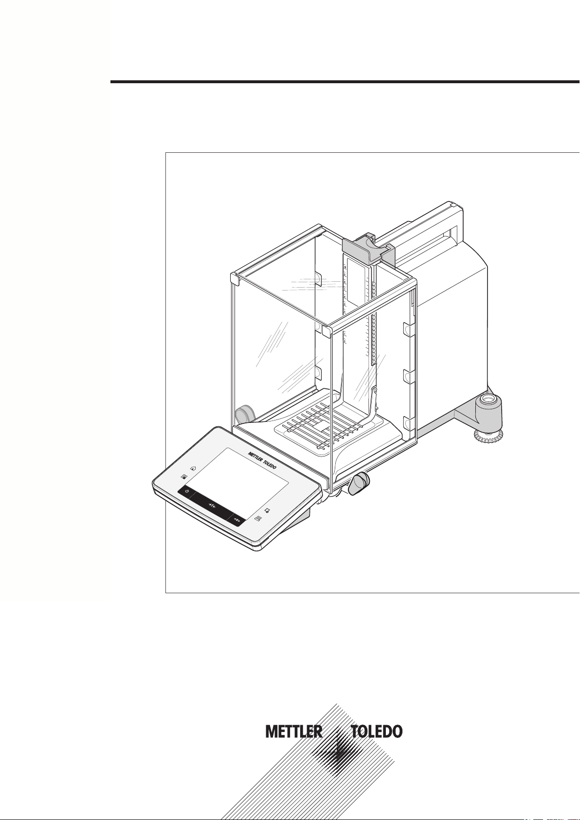
XSE204
F
F
METTLER TOLEDO
Excellence Analytical Balances
Quick Guide
XSE Models
Page 2

Page 3

Table of Contents
Introduction1 5
Safety Information2 6
Design and Function3 8
Installation and Putting into Operation4 17
Maintenance5 25
Technical Data6 26
Explanation of warnings and symbols2.1 6
Product safety information2.2 6
Overview3.1 8
Balance3.1.1 8
Terminal3.1.2 10
User interface3.2 11
Display3.2.1 11
Input dialog boxes3.2.2 12
Text and number entry3.2.2.1 13
Firmware3.2.3 13
User-specific settings3.2.3.1 13
Applications3.2.3.2 14
Application-specific settings3.2.3.3 15
System settings3.2.3.4 15
Security system3.2.4 16
Unpacking4.1 17
Scope of delivery4.2 18
Location4.3 19
Assembling the balance4.4 19
Connecting the balance4.5 21
Setting up the balance4.6 22
Weighing for the first time4.6.1 22
Switching on the balance4.6.1.1 22
Leveling the balance4.6.1.2 22
Performing a simple weighing4.6.1.3 23
Handle for operation of the side draft shield doors4.6.2 23
Cleaning5.1 25
General data6.1 26
Explanatory notes for the METTLER TOLEDO AC adapter6.2 26
Model-specific data6.3 27
Dimensions6.4 30
Table of Contents 3
Page 4

Page 5

1Introduction
Thank you for choosing a METTLER TOLEDO balance.
This balance offers numerous weighing and adjustment options with exceptional operating convenience.
METTLER TOLEDO is a leading manufacturer of balances for laboratory and production use as well as analyti
cal measuring instruments. A globally present customer service network with highly trained personnel is always
available to assist with the selection of accessories or provide advice on the optimal use of the balance.
Various models offering different performance features are available. Models offer different weighing ranges and
resolutions. Special reference is made to these features in these instructions if important for operation.
The following features are common to all models of the XSE line:
●
Fully automatic adjustment "ProFACT" using internal weights.
●
Built-in level sensor, illuminated level indicator and Leveling Assistant for fast and easy leveling.
●
Built-in applications for normal weighing, statistics, formulation, piece numbers, percent weighing, density
determination, differential weighing, pipette test and titration.
●
Integral RS232C interface.
●
Slot for second interface (optional).
●
Touch-sensitive graphic terminal ("Touch screen") with color display.
The balance conforms to current standards and directives. It supports requirements, work techniques and proto
cols as specified by all international quality assurance systems, e.g. GLP (Good Laboratory Practice), GMP
(Good Manufacturing Practice). The balance has a CE Declaration of Conformity and METTLER TOLEDO, as the
manufacturer, is certified to ISO 9001 and ISO 14001. This provides the assurance that your capital investment
is protected in the long term by high product quality and a comprehensive service package (repairs, mainte
nance, servicing, adjustment service).
Finding more information
u www.mt.com/excellence
Detailed operating instructions are on the CD-ROM.
Software version
These operating instructions refer to the originally installed firmware (software) version V 1.00.
5Introduction
Page 6
2Safety Information
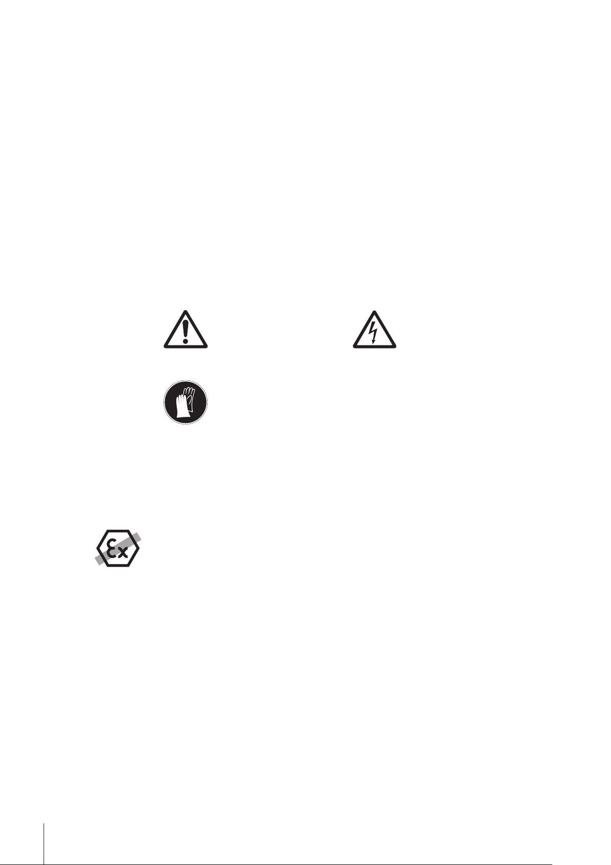
2.1Explanation of warnings and symbols
Safety notes are indicated by signal words and warning symbols and contain warnings and information about
safety issues. Ignoring safety notes can lead to personal injury, damage to the instrument, malfunctions and
erroneous results.
Signal words
WARNING for a hazardous situation with medium risk, possibly resulting in severe
injuries or death if not avoided.
CAUTION for a hazardous situation with low risk, resulting in damage to the device or
the property or in loss of data or minor or medium injuries if not avoided.
Attention (no symbol)
for important information about the product.
Note (no symbol)
for useful information about the product.
Warning symbols
General hazard Electrical shock
Mandatory signs
2.2Product safety information
Intended use
Your balance is used for weighing. Use the balance exclusively for this purpose. Any other type of use and
operation beyond the limits of technical specifications without written consent from Mettler-Toledo AG, is con
sidered as not intended.
It is not permitted to use the instrument in explosive atmosphere of gases, steam, fog, dust
and flammable dust (hazardous environments).
General safety information
This balance complies with current industry standards and the recognized safety regulations; however, it can
constitute a hazard in use. Do not open the balance housing: The balance contains no user-serviceable parts.
In the event of problems, please contact a METTLER TOLEDO representative.
Always operate and use your instrument only in accordance with the instructions contained in this manual. The
instructions for setting up your new instrument must be strictly observed.
If the instrument is not used according to these Operating Instructions, protection of the instrument may
be impaired and METTLER TOLEDO assumes no liability.
Gloves must be worn
Staff safety
These operating instructions must be read and understood before using the balance. These operating instruc
tions must be retained for future reference.
The balance must not be altered or modified in any way. Only use METTLER TOLEDO original spare parts and
accessories.
6 Safety Information
Page 7
Safety notes
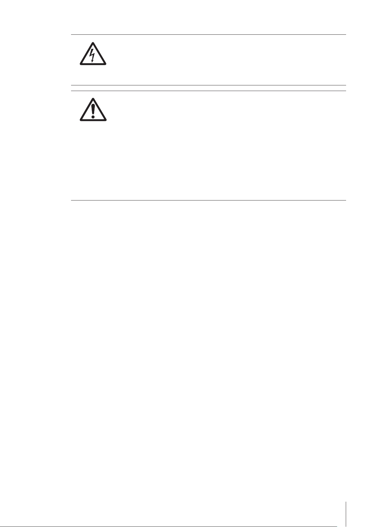
WARNING
Risk of electric shock
Use only the original universal AC adapter delivered with your balance, and check that the
voltage printed on it is the same as your local power supply voltage. Only plug the adapter
into a socket which is grounded.
CAUTION
Damage to the balance
a) Only use indoors in dry locations.
b) Do not use pointed objects to operate the keyboard!
The balance is of a very sturdy design, but is still a precision instrument. It must be han
dled with care.
c) Do not open the balance:
The balance contains no user-serviceable parts. In the event of problems, please contact
a METTLER TOLEDO representative.
d) Only use METTLER TOLEDO original accessories and peripheral devices for the balance.
These are specifically designed for the balance.
7Safety Information
Page 8
3Design and Function
METTLER TOLEDO
1
2
3
4
5
7
6
3
8 9
10
11
12
13
www.mt.com
XSE204
F
F
METTLER TOLEDO
This section describes the balance, operating and indicating elements of the terminal and the operating concept
of the balance firmware.
3.1Overview
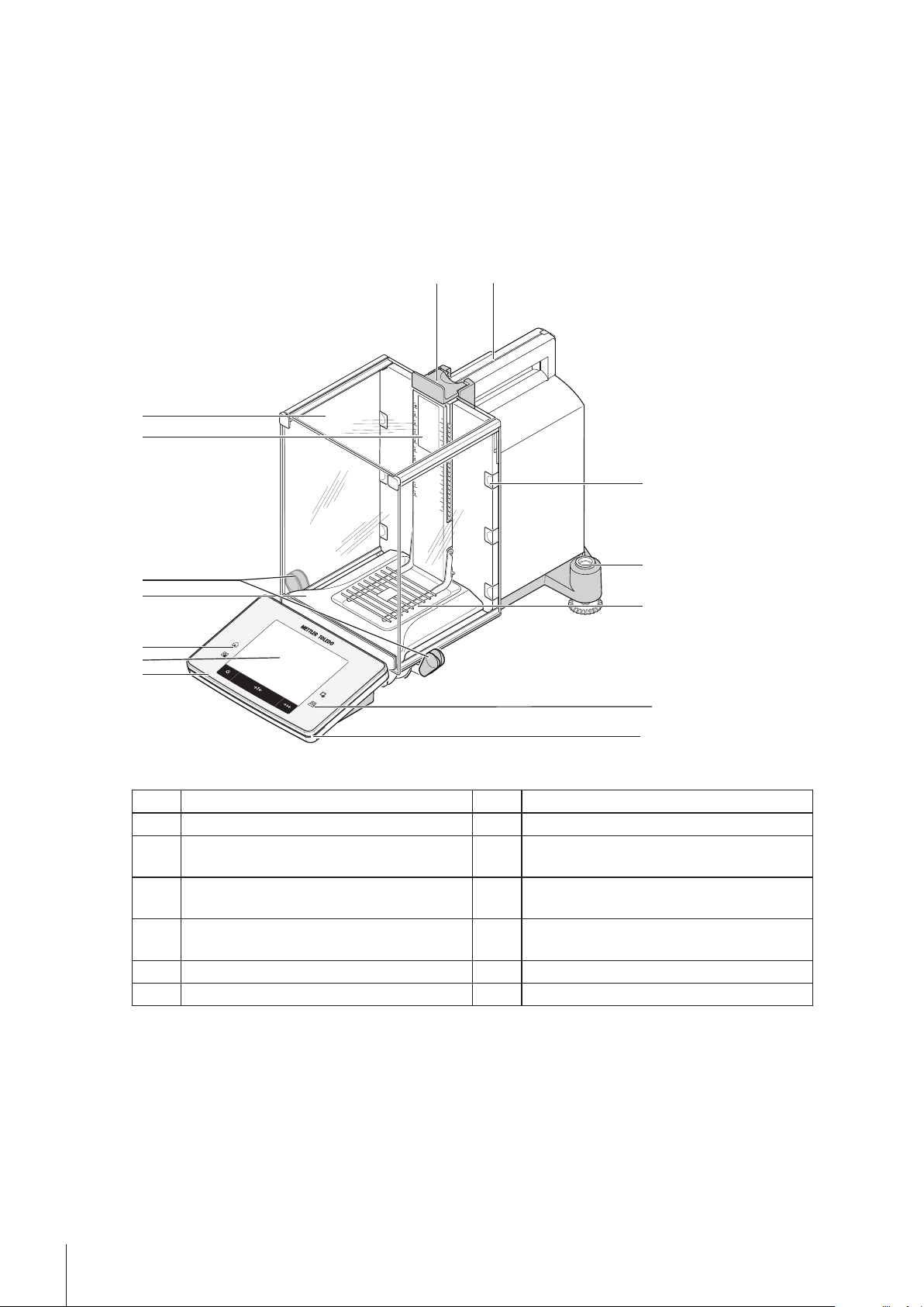
3.1.1Balance
Balance with rear connections.
Front view
1 Terminal 2 Display (touch-sensitive "Touch screen")
3 Operating keys 4 Drip tray
5 Handle for operating the draft shield side
6 Type designation
doors
7 Glass draft shield 8 Handle for operation of the top draft shield
door
9 Guide for top draft shield door and transport
handle
11 Level indicator/Level sensor 12 SmartGrid weighing pan
13 Status indicator
10 Removable clips for feeding cables or hoses
8 Design and Function
Page 9
6
7
5
4
3
2
1
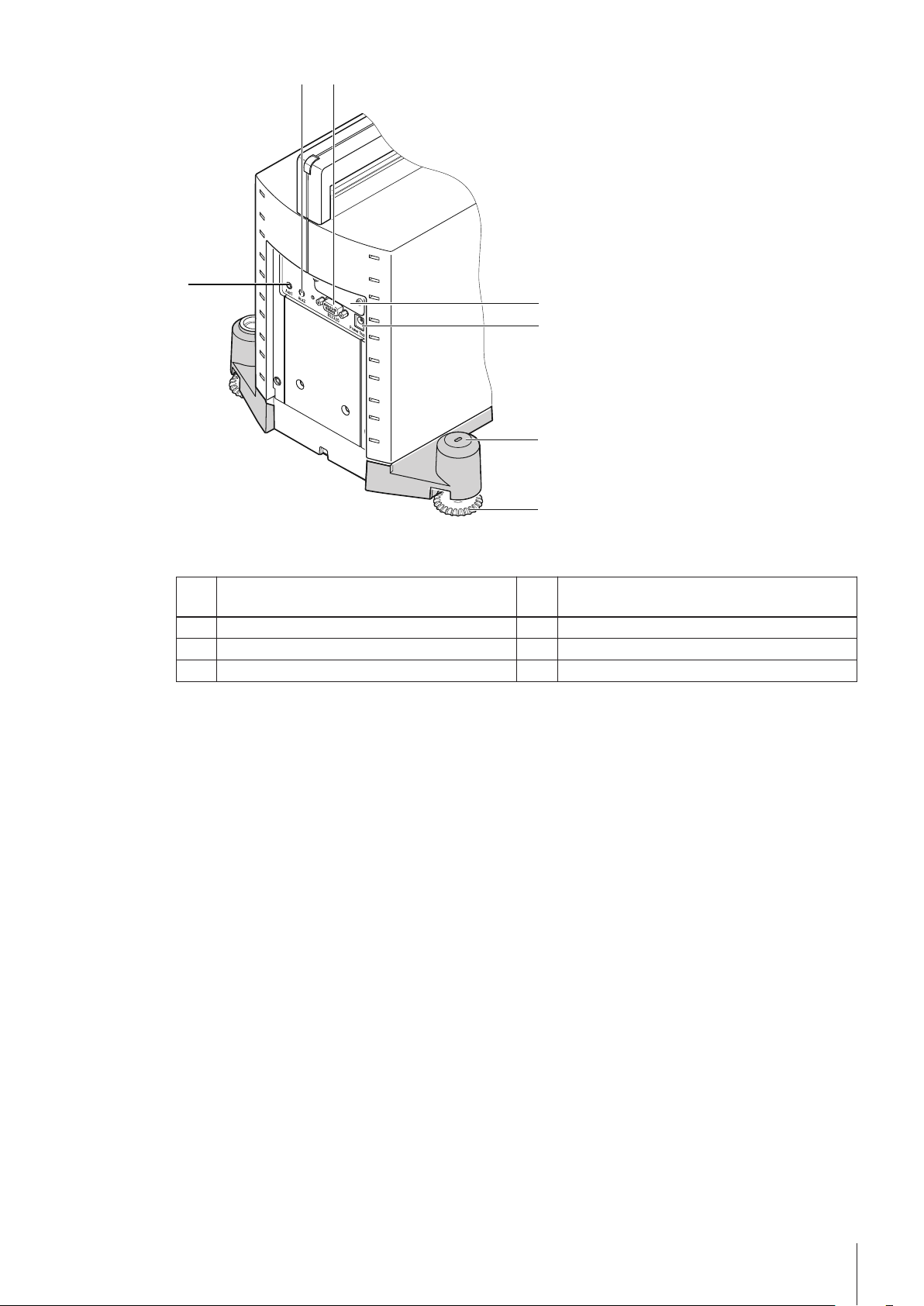
Rear
1 Aux 1 (connection for "ErgoSens", hand or foot
switch)
2 Aux 2 (connection for "ErgoSens", hand or foot
switch)
3 RS232C serial interface 4 Slot for second interface (optional)
5 Socket for AC adapter 6 Fastening point for anti-theft device
7 Foot screw
9Design and Function
Page 10
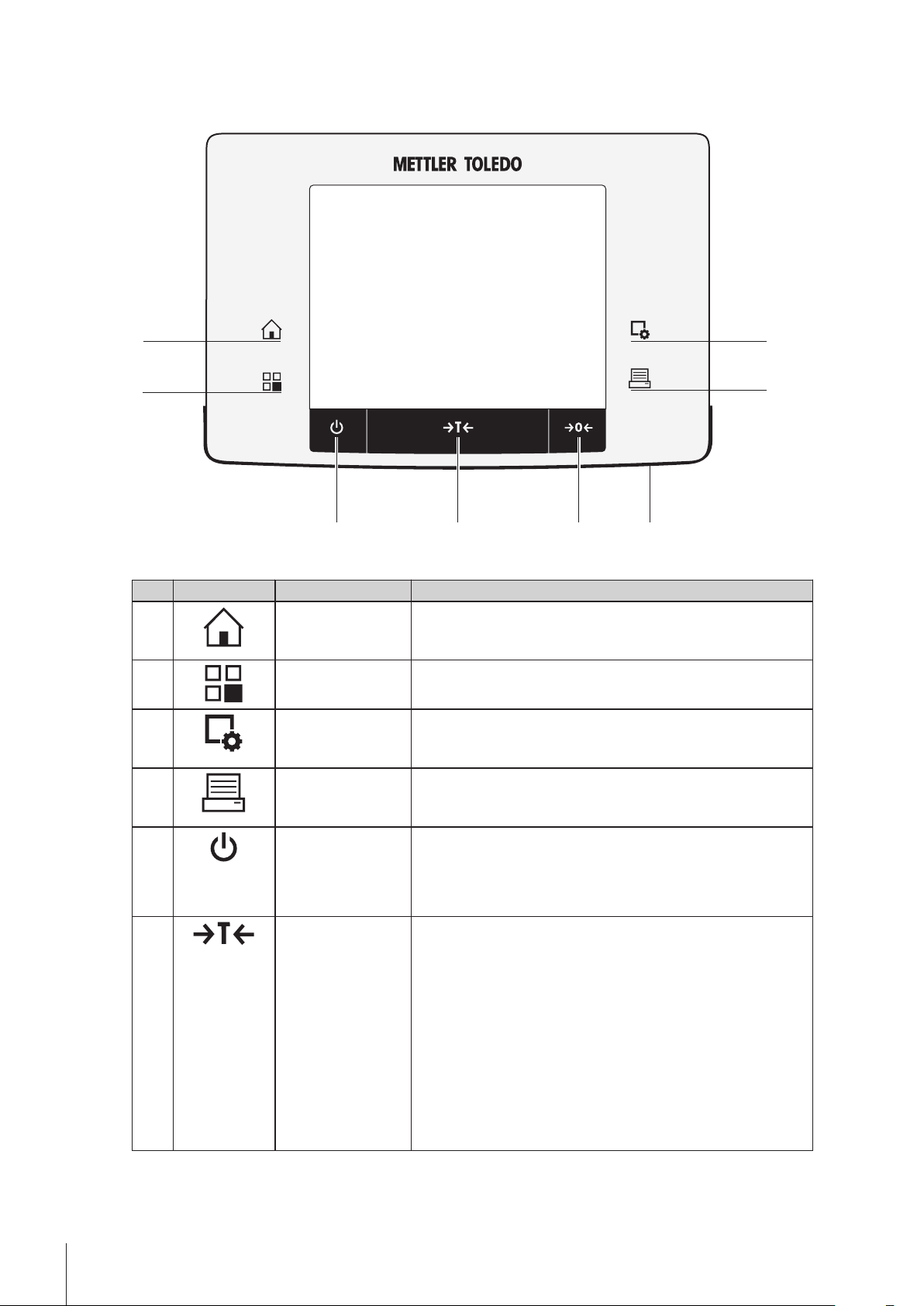
3.1.2Terminal
8
7
5
6
1
2
3
4
Key assignments and terminal connection.
Front view
Designation Explanation
1 Home This key is used to return to the user profile from any menu level
in any application. All changes made and confirmed up to this
point are automatically stored.
2 Select application This key is used to select a required application.
3 Configuration For displaying menus for the configuration of a current applica
tion. The application can be adjusted to a specific task via
numerous settings.
4 Pressure This key is used to transfer data via the interface, e.g. to a print
er. Other devices, e.g. a PC can also be connected. The data to
be transferred can be freely defined.
5 On/Off For switching the balance on and off (standby mode).
Note
It is recommended not to disconnect the balance from the power
supply unless it is not used for an extended period.
6 Tare This key is used to tare the balance manually (only necessary
for normal weighings). When the balance has been tared, the
Net symbol is displayed to indicate that all displayed weights
are net.
Note
A negative weight is not permitted. An error message is generat
ed.
When the stability detector icon extinguishes (small ring on the
left of the weight display), a stable weight is indicated.
The procedure for taring the balance is not the same as for zero
ing.
10 Design and Function
Page 11

7 Zeroing This key is used for setting a new zero point manually (only
1 22
required if the balance is used for normal weighings). After zero
ing "Zeroing", all weights (also the tare weight) apply to this
new zero point and the following applies: tare weight = 0, net
weight (= gross weight) = 0.
8 Status indicator Indicates the current balance status. The status indicator shows
that the balance is ready to use.
Green = balance is busy.
Flashing green = balance is busy, e.g. internal/external adjust
ment in progress.
Yellow = task pending, e.g. automatic external adjustment
pending when a reminder date for a service or test is reached.
Red = balance cannot/must not be used, if e.g. the balance is
not correctly leveled. The balance has underload or overload
when starting.
Rear
1 System connection (terminal cable) 2 Foot
3.2User interface
3.2.1Display
The illuminated, color display of the terminal is a touch screen, i.e. a touch-sensitive screen. It can be used for
displaying data, entering settings and selecting functions by tapping the screen.
Note
Depending on country-specific requirements, non-calibrated decimal places are highlighted on calibrated bal
ances.
CAUTION
Do not touch the touch screen with pointed or sharp objects!
This may damage the touch screen.
11Design and Function
Page 12

Designation Explanation
1 Application name Select application.
The application menu can be selected by touching this zone. The application can
be selected here. This menu can also be displayed by pressing [ ].
2 Date The date can be changed by tapping this zone.
3 Time The time can be changed by tapping this zone.
4 Status icons These status icons indicate special balance statuses (e.g. service due, adjust
ment required, battery replacement).
A separate selection window is displayed when the icons are tapped. When the
icons are tapped, their functions are explained.
5 Weight value Tapping the weight displays a window showing the result in a large format. This
is useful for reading a weight from a certain distance.
6 Weighing unit The required weighing unit can be changed by tapping the weighing unit, e.g.
from mg to g.
7 SmartTrac SmartTrac is a graphic weighing-in aid, which shows at a glance an already
used and still available weighing range. Various display modes can be selected
for SmartTrac or deactivated by tapping this area.
8 Function keys This area is reserved for Function Keys enabling direct access to frequently
required functions and application settings. If more than 5 function keys are acti
vated, these can be selected with the arrow keys.
9 Information fields This area is used for displaying additional information (information fields) relat
ing to an active application. Tapping the information field enables Information
fields and Function Keys to be displayed directly via menu selection. The level
ing assistant can also be started.
Screen saver
If the balance is not used for 15 minutes, the display is automatically dimmed and the pixels are inverted about
every 15 seconds. When the balance is used again (e.g. load weight, press key), the display returns to a nor
mal state.
3.2.2Input dialog boxes
The keyboard dialog box is used to enter characters such as letters, numbers and special characters.
12 Design and Function
Page 13

3.2.2.1Text and number entry
1
2
3
Designation Explanation
1 Data field Displays (entered) alphanumeric and numeric characters.
2 Keyboard Data input area
3 Selection Selects various keyboards.
1 Enter the designation.
2 Confirm with [OK].
Delete last character
Tap once to place the cursor at
the end of the data field.
Function
3.2.3Firmware
The firmware controls all balance functions. It enables the balance to be adjusted to a specific working environ
ment.
The firmware is divided as follows:
●
Applications
●
Application-specific settings
●
System settings
●
User-specific settings
Note
A displayed menu can be left at any time by repressing the same key as used for its selection.
3.2.3.1User-specific settings
These settings can be used to adjust the balance to suit the tasks and work techniques of individual users.
13Design and Function
Page 14

>
1
2
3
1
2
3
System
>
Designation Explanation
1 Title bar The title bar displays elements for user orientation and information.
2 Contents area The contents area is the main work area for menus and applications. The con
tents depend on the specific application or initiated action.
3 Action bar The action bar contains action buttons for performing specific actions required in
the active dialog box and are available (e.g. [Exit], [STD], [C], [OK]).
1 Settings can be changed by tapping the respective button.
2 To leave the settings, select [Exit].
3 To change the system settings, tap [System].
Function
Exit Exit settings
System Display system settings
3.2.3.2Applications
Applications are firmware modules for performing specific weighing tasks. The balance is provided with various
applications on delivery. After switching on the balance, the last active user profile and last used application are
loaded. The applications are available under the [ ] key. Instructions for working with standard applications
are provided in the respective sections.
Designation Explanation
1 Title bar The title bar displays elements for user orientation and information.
2 Contents area The contents area is the main work area for menus and applications. The con
tents depend on the specific application or initiated action.
3 Action bar The action bar contains action buttons for performing specific actions required in
the active dialog box and are available (e.g. [Exit], [STD], [C], [OK]).
– An application can be selected by tapping the corresponding button.
14 Design and Function
Page 15

Function
5
4
1
2
3
System Display system settings
3.2.3.3Application-specific settings
These settings can be used to adjust the applications to suit specific requirements. The available setting options
depend on the selected application. Pressing the [ ] key opens the multipage menu with settings for a cur
rently active application. Information on the individual setting options is provided in the section relating to the
respective application.
Designation Explanation
1 Title bar The title bar displays elements for user orientation and information.
2 Contents area The contents area is the main work area for menus and applications. The con
3 Action bar The action bar contains action buttons for performing specific actions required in
4 Button Edit/Select settings (e.g. [Define], [On], [Off]). The contents depend on the
5 Arrow The arrow buttons are used to page forward or back.
1 Settings can be changed by tapping the respective button.
2 Confirm with [OK].
3.2.3.4System settings
System settings (e.g. settings for peripheral devices) are independent of the applications and apply to the entire
weighing system. System settings can be displayed by pressing [ ] and subsequently the [System] button.
tents depend on the specific application or initiated action.
the active dialog box and are available (e.g. [Exit], [STD], [C], [OK]).
application.
Function
Page forward
Page back
15Design and Function
Page 16

>
1
2
3
System
Designation Explanation
1 Title bar The title bar displays elements for user orientation and information.
2 Contents area The contents area is the main work area for menus and applications. The con
tents depend on the specific application or initiated action.
3 Action bar The action bar contains action buttons for performing specific actions required in
the active dialog box and are available (e.g. [Exit], [STD], [C], [OK]).
1 Settings can be changed by tapping the respective button.
2 To leave the settings, tap [Exit].
3.2.4Security system
The balance has a comprehensive security system with which individual access rights can be defined at
administrator and user level. Access to protected menu areas requires the entry of an identification (ID) and a
password. On delivery of the balance, only the [Administrator] settings in the system settings are protected.
When an ID and password protected menu area is selected, an alphanumeric keyboard is initially displayed for
entry of the ID.
1 Enter your ID.
- Case sensitive, tap the [a...z] and [A...Z] button to switch between upper and lower case.
- To enter numbers, tap the [0...9] button.
- Incorrect entries can be deleted character by character with the arrow key .
Note
Entry can be interrupted at any time by tapping [C].
2 After entering the full ID, tap [OK].
A further dialog box is displayed for entering the password.
3 Enter the password (for security reasons, this is displayed with asterisks instead of plain text) and confirm
with [OK].
If the ID and password are correct, the selected menu area is displayed or the required action initiated. If
these are incorrect, an error message is displayed with a request to enter them again.
CAUTION
Remember IDs and passwords!
Protected menu areas cannot be accessed without ID or password.
– Note IDs and passwords and keep them in a safe place.
16 Design and Function
Page 17

4Installation and Putting into Operation
8
1
2
3
4
5
67
4.1Unpacking
Open the balance packaging. Check the balance for transport damage. Immediately inform a METTLER TOLEDO
representative in the event of complaints or missing accessories.
Note
Retain all parts of the packaging. This packaging offers the best possible protection for transporting the bal
ance.
– Use the lifting strap to lift the balance out of the packaging box.
Overview
1 Lifting strap
2 Top packaging
3 Operating instructions and other important documents
4 Balance
5 Set with draft-shield doors and terminal support
6 Set with AC adapter, power supply cable, drip tray, Smart
Grid, SmartGrid cover, SmartPrep single-use funnel and
ErgoClip "Basket" (basket for small weighing objects)
7 Terminal
Note
The terminal is connected to the balance with a cable.
8 Bottom packaging
1 Remove the lifting strap (1).
2 Remove the top packaging (2).
1 Remove the operating instructions (3).
2 Remove the set with AC adapter (6).
3 Remove the set with draft shield doors (5).
17Installation and Putting into Operation
Page 18

1 Carefully remove the terminal from the bottom packaging.
2 Remove the protective cover.
Note
Since the terminal is connected to the balance with a cable, only
withdraw the balance slightly from the packaging in order to
remove the protective cover.
1 Place the terminal at the front of the balance.
2 Hold the balance by the guide or handle. Hold the terminal
firmly with the other hand. Pull out both components together
from the bottom packaging.
1 Place the balance with the terminal at the site of use.
2 Remove the cover from the balance.
3 Remove the transport protection (9) of the weighing pan sup
port.
4.2Scope of delivery
Check the delivery for completeness. The following accessories are part of the standard equipment of the bal
ance:
●
Balance with terminal
•
RS232C interface
•
Slot for second interface (optional)
•
Feedthroughs for below-the-balance weighing and for antitheft device
●
Set with draft-shield doors and terminal support
●
SmartGrid
●
SmartGrid cover, chromium-nickel steel
●
SmartPrep single-use funnel (2 pieces)
●
Drip tray
●
AC adapter with country-specific power cable
●
Protective cover for the terminal
●
Cleaning brush
●
ErgoClip "Basket" (basket for small weighing objects)
18 Installation and Putting into Operation
Page 19

●
2
1
2
1
Production certificate
●
CE declaration of conformity
●
Operating instructions or Quick Start Guide; printed or on CD-ROM, depending on country of use
4.3Location
An optimal location will ensure accurate and reliable operation of the balance. The surface must be able to
safely take the weight of the balance when fully loaded. The following local conditions must be observed:
Note
If the balance is not horizontal at the outset, it must be leveled during commissioning.
●
The balance must only be used indoors and up to a maxi
mum altitude of 4,000 m above sea level.
●
Before switching on the balance, wait until all parts are at
room temperature (+5 to 40°C).
The humidity must be between 10% and 80% non-condens
ing.
●
The power plug must be accessible at all times.
●
Firm, horizontal and vibration-free location.
●
Avoid direct sunlight.
●
No excessive temperature fluctuations.
●
No strong drafts.
Further information can by found in Weighing the Right Way.
4.4Assembling the balance
1 Remove the transport protection (1).
2 Insert the drip tray (2).
Insert the tray from the front above the bottom plate up to the
partition.
1 Insert the SmartGrid from the front.
2 Check that the SmartGrid (1) (2) is correctly hooked in on
both sides.
19Installation and Putting into Operation
Page 20

1 Insert the top draft shield door (1) at an angle (slightly below
1
2
A
A
4
2
3
1
30 degrees) into the rear guide.
2 Carefully fold the draft shield door (2) downwards, see fig
ure.
The handles (A) must be folded outwards to mount the side
draft shield doors.
1 Mount the draft shield side doors according to the following
instructions, see figure below.
2 Mount the side doors at an angle of about 30° in the 2 open
ings, see following figure.
3 Check that the side doors are correctly mounted as described.
4 Mount the side door so that it clicks in place in the balance.
The side door will move easily when correctly mounted.
5 Fold the handle of the side draft shield door inwards.
6 Mount the second draft shield side door. The procedure is
identical.
7 Move the side doors fully back.
1 Fit the front draft shield glass (2).
Insert the glass at an angle into the bottom of the balance at
the front until the two hooks of the front draft shield glass rest
on the rollers (1).
2 Move the front draft shield glass upwards until it engages.
20 Installation and Putting into Operation
Page 21

1 Insert the terminal support.
2 Place the cable in the guide of the terminal support.
3 Insert the terminal support into the opening in the front draft
shield glass.
The terminal support must engage with a click.
1 Mount the terminal.
2 Place the terminal in the center of the support.
3 Push the terminal against the balance until it folds down eas
ily at the front of the terminal support.
4 Insert the cable into the balance.
Attention
The balance and terminal are not connected by the terminal support! Always hold the balance and terminal
firmly during transport.
Note
The terminal can also be placed in the area of the balance without the terminal support if the cable is of suffi
cient length.
4.5Connecting the balance
WARNING
Risk of electric shock
a) To connect the balance, only use the supplied three-core power cord with equipment
grounding conductor.
b) Only connect the balance to a three-pin power socket with earthing contact.
c) Only standardized extension cable with equipment grounding conductor must be used for
operation of the balance.
d) Intentional disconnection of the equipment grounding conductor is forbidden.
The balance is supplied with an AC adapter and country-specific power cord. The AC adapter is suitable for use
with the following voltage range:
100 – 240 VAC, 50/60Hz.
Attention
●
Check whether your local power supply falls within this range. If this is not the case, under no circum
stances connect the AC adapter to the power supply, but contact a METTLER TOLEDO representative.
●
The power plug must be accessible at all times.
●
Prior to use, check the power cord for damage.
●
Route the cable in such a way that it cannot be damaged or cause a hindrance when working.
●
Ensure that no liquid comes into contact with the AC adapter.
21Installation and Putting into Operation
Page 22

Balance and terminal are at the final location.
1 Connect the AC adapter (1) to the connection socket (2) at
the rear of the balance.
2 Connect the AC adapter (1) to the power supply.
The balance performs a self-test after connection to the power
supply and is then ready to use.
4.6Setting up the balance
4.6.1Weighing for the first time
After commissioning the new balance, the first weighing can be carried out. This will also familiarize you with
the operation of the balance.
If the balance is not aligned exactly horizontal, a warning text is generated after switching on the balance with
the request to level the balance.
4.6.1.1Switching on the balance
Startup
Balance is connected to the power supply.
Terminal and balance are interconnected.
– Press [ ].
Display appears.
Balance is ready to use.
4.6.1.2Leveling the balance
The balance has a built-in level sensor which permanently monitors correct horizontal alignment.
If the level sensor detects incorrect leveling, the status indicator at
the terminal shows red. A warning text is displayed and an audi
ble warning generated. A status icon also appears in the top right
corner of the display.
22 Installation and Putting into Operation
Page 23

1 To start the leveling assistant, tap [LevelGuide] in the warn
ing message.
Window with level indicator is displayed in real-time.
2 Observe the level indicator on the screen.
The air bubble in the level indicator shows red with incor
rect alignment.
The leveling assistant indicates with red arrows the direc
tion in which the two foot screws at the rear of the balance
must be turned.
3 Turn the foot screw until the air bubble is located in the inner
circle of the level indicator.
The air bubble in the level indicator shows green with cor
rect alignment.
The status indicator at the terminal shows green.
4 Tap [OK].
A message recommending adjustment of the balance is
displayed.
5 Tap [Adjust.int] to adjust the balance.
4.6.1.3Performing a simple weighing
To perform a simple weighing, only the keys in the lower part of the terminal are required. The balance has sep
arate keys for zeroing [ ] and taring [ ].
Zeroing
– Press [ ].
Zeroing
After zeroing, all weights (also the tare weight) apply to this new zero point and the following apply: tare weight
= 0, net weight (= gross weight) = 0.
Taring
Note
A negative weight is not permitted. An error message is generated. When the stability detector icon extinguishes
(small ring left of the weight display), the indication is stable. The weight is displayed.
If a weighing container is used, the balance must first be set to zero.
1 Place the container on the balance.
2 Press [ ].
The balance is tared.
The weight of the container is set as the new tare weight and the previous tare (if available) is overwritten.
The Net display signals that all indicated weights are net weights.
Congratulations!
The first weighing is now complete. The following sections contain further information about the extensive func
tions and applications of this balance.
4.6.2Handle for operation of the side draft shield doors
The draft shield of the balance can be adjusted to the ambient conditions, weighing method and material to be
weighed.
The position of the handles determines which draft shield doors (left, right or both) are opened.
Try out different combinations by moving the handles up or down. We recommend setting the glass draft shield
so that only the door required for loading is opened. The balance then operates faster due to less disturbing air
flows than with a fully open glass draft shield.
23Installation and Putting into Operation
Page 24

Note
It is recommended to make connections when the draft shield is closed.
1 Move the side door handle downwards.
2 Move the doors fully back.
24 Installation and Putting into Operation
Page 25

5Maintenance
5.1Cleaning
Periodically clean the weighing pan, the drip tray, the housing, and the terminal of your balance using the
brush supplied with it. The maintenance interval depends on your standard operating procedure (SOP).
Please observe the following notes:
WARNING
Risk of electric shock
a) Disconnect the balance from the power supply prior to cleaning and maintenance.
b) Only use METTLER TOLEDO power cords, if these need to be replaced.
c) Ensure that no liquid comes into contact with the balance, terminal or AC adapter.
d) Do not open the balance, terminal or AC adapter.
These contain no user-serviceable parts.
CAUTION
Damage to balance
Under no circumstances use cleaning agents containing solvents or abrasive agents, as this
can damage the terminal overlay.
Cleaning
Your balance is made from high quality, resistant materials and can therefore be cleaned with a commercially
available, mild cleaning agent.
1 To clean the weighing chamber thoroughly, swing out the draft shield glass panels from the balance and
remove them from their fastening points.
2 Carefully lift the front of the weighing pan and lift it out of the guide.
3 Remove the drip tray from the balance.
4 Ensure that these parts are correctly positioned when refitted.
Note
Contact a METTLER TOLEDO representative to find about the service options available – regular maintenance
by an authorized service engineer will ensure consistent weighing accuracy over the long term and extend the
service life of the balance.
25Maintenance
Page 26

6Technical Data
6.1General data
Power supply
AC adapter: Primary: 100–240VAC, -15%/+10%, 50/60Hz
Cable for AC adapter: 3-core, with country-specific plug
Balance power supply: 12VDC ±3%, 2.25A, maximum ripple: 80mVpp
Protection and standards
Overvoltage category: II
Degree of pollution: 2
Protection: Protected against dust and water
Standards for safety and EMC: See Declaration of Conformity
Range of application: For use only in closed interior rooms
CAUTION
Only use an approved AC adapter with a current-limited SELV output.
Ensure correct polarity
Secondary: 12 V DC ±3%, 2.5 A (with electronic overload pro
tection)
Environmental conditions
Height above mean sea level: Up to 4000m
Ambient temperature: 5–40°C
Relative air humidity: Max. 80% up to 31°C, linearly decreasing to 50% at 40°C,
noncondensing
Warm-up time: At least 120 minutes after connecting the balance to the power
supply; when switched on from standby-mode, the balance is
ready for operation immediately
Materials
Housing: Die-cast aluminum, plastic, chrome steel and glass
Terminal: Die-cast zinc, chromed and plastics
SmartGrid: Chrome-nickel steel X5CrNi18-10
6.2Explanatory notes for the METTLER TOLEDO AC adapter
The certified external power supply which conforms to the requirements for Class II double insulated equipment
is not provided with a protective earth connection but with a functional earth connection for EMC purposes. This
earth connection IS NOT a safety feature. Further information about conformance of our products can be found
in the brochure "Declaration of Conformity" which is coming with each product.
In case of testing with regard to the European Directive 2001/95/EC the power supply and the balance have to
be handled as Class II double insulated equipment.
Consequently an earth bonding test is not required. Similarly it is not necessary to carry out an earth bonding
test between the supply earth conductor and any exposed metalwork on the balance.
Because the balance are sensitive to static charges a leakage resistor, typically 10 kΩ, is connected between
the earth connector and the power supply output terminals. The arrangement is shown in the equivalent circuit
diagram. This resistor is not part of the electrical safety arrangement and does not require testing at regular
intervals.
26 Technical Data
Page 27

10 kΩ coupling resistor for
electrostatic discharge
Input 100…240 V
AC Output 12 VDC
Double Insulation
Plastic Housing
P
N
E
AC
DC
Equivalent circuit diagram
6.3Model-specific data
Limit values
Maximum capacity 120 g 220 g
Readability 0.1 mg 0.1 mg
Tare range (from…to) 0 … 120 g 0 … 220 g
Maximum capacity in fine range 41 g 81 g
Readability in fine range 0.01 mg 0.01 mg
Repeatability (at nominal load) sd 0.1 mg (100 g) 0.1 mg (200 g)
Repeatability (at low load) sd 0.05 mg (5 g) 0.05 mg (10 g)
Repeatability in fine range (at low load) sd 0.02mg (5g) 0.02mg (5g)
Linearity deviation 0.2 mg 0.2 mg
Eccentric deviation (test load)
Sensitivity offset (test weight) 0.8 mg (100 g) 0.8 mg (200 g)
Sensitivity temperature drift
Sensitivity stability
3)
Typical values
Repeatability (at low load) sd 0.04 mg 0.04 mg
Repeatability in fine range sd 0.01 mg (5g) 0.01 mg (10g)
Linearity deviation 0.13 mg 0.13 mg
Eccentric deviation (test load)
Sensitivity offset (test weight) 0.4 mg (100 g) 0.6 mg (200 g)
Minimum weight (according to USP) 80 mg 80 mg
Minimum weight (according to USP) in fine
range
Minimum weight (U=1%, k=2) 8 mg 8 mg
Minimum weight (U=1%, k=2) in fine range 2mg 2mg
Setting time 1.5 s 1.5 s
Setting time in fine range 3 s 3 s
Dimensions
Balance dimensions (W × D × H) 263 × 482 × 322mm 263 × 482 × 322mm
Weighing pan dimensions 78 × 73 mm (W × D) 78 × 73 mm (W × D)
Typical uncertainties and supplementary data
Repeatability sd 0.04 mg
Repeatability in fine range sd 0.01 mg
Differential linearity deviation sd √(40 pg·Rnt) √(20 pg·Rnt)
Differential eccentric load deviation sd 0.0003%·Rnt 0.00015%·Rnt
Sensitivity offset sd 0.0002%·Rnt 0.00008%·Rnt
Minimum weight (according to USP) 80 mg +0.06%·Rgr 80 mg +0.03%·Rgr
Minimum weight (according to USP) in fine
range
Minimum weight (U=1%, k=2) 8 mg +0.006%·Rgr 8 mg +0.003%·Rgr
Minimum weight (U=1%, k=2) in fine range 2 mg +0.005%·Rgr 2 mg +0.0024%·Rgr
Weighing time 4 s 4 s
1)
2)
1)
XSE105DU XSE205DU
0.3 mg (50 g) 0.3 mg (100 g)
0.00015%/°C 0.00015%/°C
0.0002%/a 0.0002%/a
0.15 mg (50 g) 0.16 mg (100 g)
20mg 20mg
0.04 mg
+0.00003%·Rgr
+0.000015%·Rgr
0.01 mg
+0.000025%·Rgr
+0.000012%·Rgr
20 mg +0.05%·Rgr 20 mg +0.024%·Rgr
27Technical Data
Page 28

XSE105DU XSE205DU
Weighing time in fine range 6 s 6 s
Interface update rate 23/s 23/s
Usable height of draft shield 235 mm 235 mm
Weight of balance 9.1 kg 9.1 kg
Number of built-in reference weights 2 2
Weights for routine testing
OIML CarePac
ASTM CarePac
Weights
Weights
100 g F2, 5 g E2
#11123002
100 g 1, 5 g 1
#11123102
200 g F2, 10 g F2
#11123001
200 g 1, 10 g 1
#11123101
sd = Standard deviation Rnt = Net weight (sample weight)
Rgr = Gross weight a = Year (annum)
1)
Valid for compact objects
3)
On DeltaRange models: fine range starts at zero load (gross)
2)
After adjustment with built-in reference weight
XSE104 XSE204
Limit values
Maximum capacity 120 g 220 g
Readability 0.1 mg 0.1 mg
Tare range (from…to) 0 … 120 g 0 … 220 g
Maximum capacity in fine range – –
Readability in fine range – –
Repeatability (at nominal load) sd 0.1 mg (100 g) 0.1 mg (200 g)
Repeatability (at low load) sd 0.07 mg (5 g) 0.07 mg (10 g)
Repeatability in fine range (at low load) sd – –
Linearity deviation 0.2 mg 0.2 mg
Eccentric deviation (test load)
1)
0.3 mg (50 g) 0.3 mg (100 g)
Sensitivity offset (test weight) 1 mg (100 g) 1 mg (200 g)
Sensitivity temperature drift
Sensitivity stability
2)
3)
0.00015%/°C 0.00015%/°C
0.0002%/a 0.0002%/a
Typical values
Repeatability (at low load) sd 0.04 mg 0.04 mg
Repeatability in fine range sd – –
Linearity deviation 0.13 mg 0.13 mg
Eccentric deviation (test load)
1)
0.15 mg (50 g) 0.16 mg (100 g)
Sensitivity offset (test weight) 0.6 mg (100 g) 0.8 mg (200 g)
Minimum weight (according to USP) 80 mg 80 mg
Minimum weight (according to USP) in fine
– –
range
Minimum weight (U=1%, k=2) 8 mg 8 mg
Minimum weight (U=1%, k=2) in fine range – –
Setting time 1.5 s 1.5 s
Setting time in fine range – –
Dimensions
Balance dimensions (W × D × H) 263 × 482 × 322mm 263 × 482 × 322mm
Weighing pan dimensions 78 × 73 mm (W × D) 78 × 73 mm (W × D)
Typical uncertainties and supplementary data
Repeatability sd 0.04 mg
+0.00003%·Rgr
0.04 mg
+0.000015%·Rgr
Repeatability in fine range sd – –
Differential linearity deviation sd √(40 pg·Rnt) √(20 pg·Rnt)
Differential eccentric load deviation sd 0.0003%·Rnt 0.00015%·Rnt
Sensitivity offset sd 0.0002%·Rnt 0.00012%·Rnt
Minimum weight (according to USP) 80 mg +0.06%·Rgr 80 mg +0.03%·Rgr
Minimum weight (according to USP) in fine
– –
range
Minimum weight (U=1%, k=2) 8 mg +0.006%·Rgr 8 mg +0.003%·Rgr
Minimum weight (U=1%, k=2) in fine range – –
Weighing time 4 s 4 s
Weighing time in fine range – –
Interface update rate 23/s 23/s
28 Technical Data
Page 29

XSE104 XSE204
Usable height of draft shield 235 mm 235 mm
Weight of balance 9.1 kg 9.1 kg
Number of built-in reference weights 2 2
Weights for routine testing
OIML CarePac
ASTM CarePac
Weights
Weights
100 g F2, 5 g E2
#11123002
100 g 1, 5 g 1
#11123102
200 g F2, 10 g F1
#11123001
200 g 1, 10 g 1
#11123101
sd = Standard deviation Rnt = Net weight (sample weight)
Rgr = Gross weight a = Year (annum)
1)
Valid for compact objects
3)
On DeltaRange models: fine range starts at zero load (gross)
2)
After adjustment with built-in reference weight
29Technical Data
Page 30

6.4Dimensions
METTLER TOLEDO
194
57
59
300
150
186
78
322
252176.5
229
482
73
296
263
151
150
262
129
Dimensions in mm.
30 Technical Data
Page 31

Page 32

Mettler-Toledo AG, Laboratory & Weighing Technologies
CH-8606 Greifensee, Switzerland
Tel. +41 (0)44 944 22 11
Fax +41 (0)44 944 30 60
www.mt.com
www.mt.com/excellence
For more information
Subject to technical changes.
© Mettler-Toledo AG 12/2013
30089512B en
*30089512*
 Loading...