

Page 1
www.mt.com
XSE2
04
METTLE
R
TOLEDO
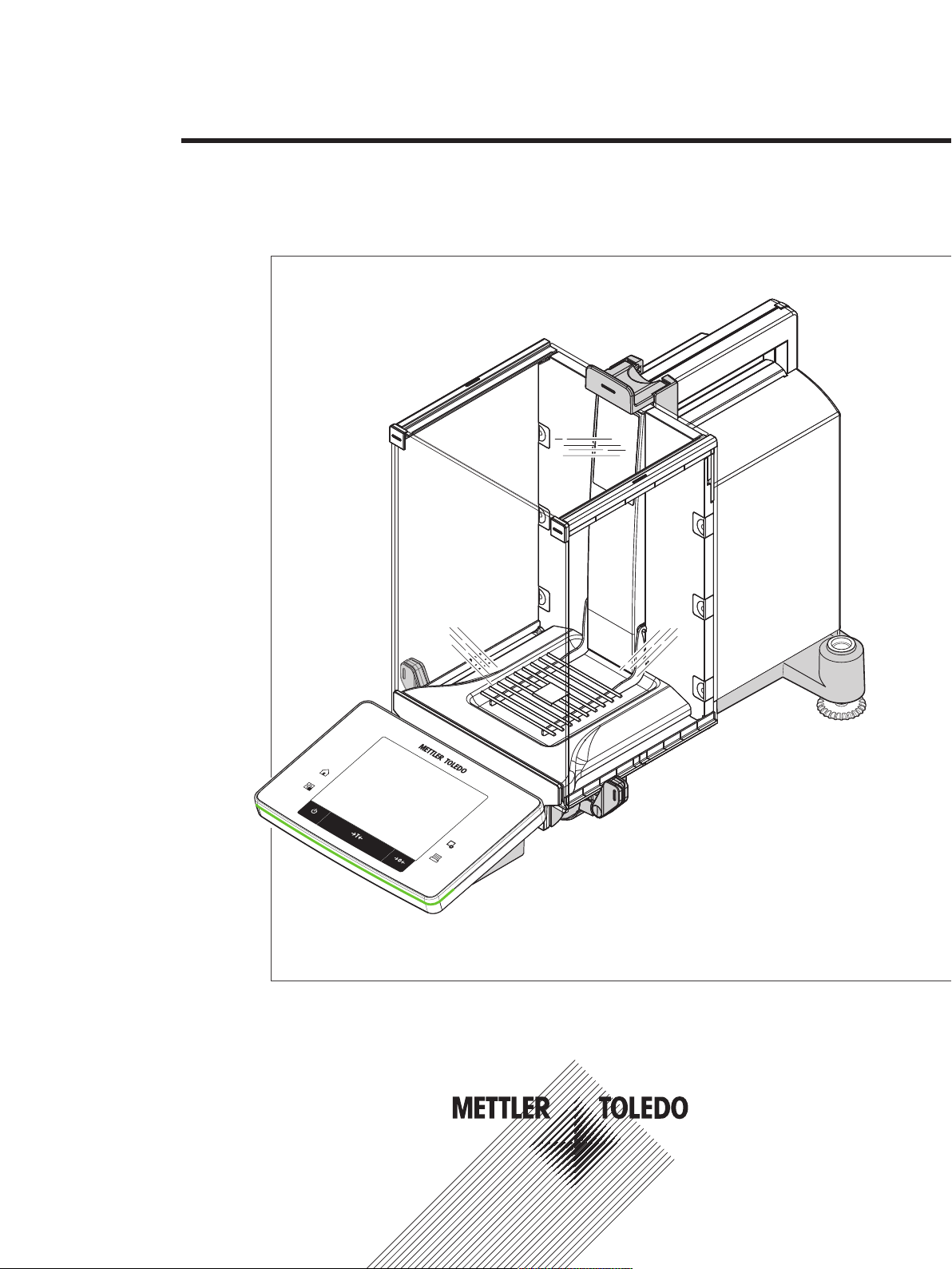
Analytical Balances
XSE models
Operating Instructions
Page 2

Page 3

Table of Contents
1 Introduction 7
2 Safety Information 8
3 Design and Function 10
4 Installation and Putting into Operation 17
1.1 Conventions and symbols used in these operating instructions 7
2.1 Explanation of warnings and symbols 8
2.2 Product safety information 8
3.1 Overview 10
3.1.1 Balance 10
3.1.2 Terminal 11
3.2 User interface 12
3.2.1 Display 12
3.2.2 Input dialog boxes 13
3.2.3 Firmware 14
3.2.3.1 System settings 14
3.2.3.2 User-specific settings 14
3.2.4 Security system 16
4.1 Unpacking 17
4.2 Scope of delivery 18
4.3 Selecting the location 19
4.4 Assembling the balance 19
4.5 Connecting the balance 22
4.6 Setting up the balance 23
4.6.1 Handle for operation of the side draft shield doors 23
4.6.2 Performing a simple weighing 24
4.6.3 Setting the reading angle and positioning the terminal 24
4.6.3.1 Changing the reading angle 24
4.6.3.2 Place terminal separately 25
4.6.4 Below-the-balance weighing 25
4.6.5 Mounting the ErgoClips 26
4.6.6 Fitting the SmartGrid cover 26
4.7 Transporting the balance 26
4.7.1 Transport over short distances 27
4.7.2 Transport over long distances 27
5 System Settings 30
5.1 Adjustment/Test 32
5.1.1 Test/Adjustment - weight settings 34
5.1.2 Test sequences 35
5.1.2.1 Method 36
5.1.2.2 Action if failure 42
5.1.3 Tasks 43
5.1.3.1 Assigning a test sequence to a task. 43
5.1.4 ProFACT/int. Adjustment 44
5.1.4.1 Definition of parameters for ProFACT 44
5.1.5 Automatic adjustment with an external test weight 45
5.1.5.1 Definition of parameters for automatic adjustment 46
5.1.6 Testing the adjustment with an external test weight 46
5.1.6.1 Definition of parameters for testing the adjustment 46
5.1.7 Test with WeightLink 46
5.1.8 Test history 47
5.1.9 Protocol – Definition of adjustment and test reports 48
5.2 Info 48
Table of Contents 1Analytical Balances
Page 4

5.3 Standby 49
5.4 Date/Time 49
5.5 Peripherals 50
5.6 Option 52
5.7 Level sensor 52
5.8 User settings 53
5.8.1 Overview of user settings 53
5.8.2 Weighing parameters 54
5.8.2.1 Weighing mode 55
5.8.2.2 Ambient conditions 55
5.8.2.3 Measured value release 56
5.8.2.4 AutoZero 56
5.8.3 User 56
5.8.3.1 User name 57
5.8.3.2 Language 57
5.8.3.3 User ID and password 57
5.8.4 Terminal 58
5.8.4.1 Brightness 58
5.8.4.2 Color selection 59
5.8.4.3 Beep 59
5.8.4.4 Touch function 59
5.8.4.5 Touch adjustment 59
5.8.4.6 Optical key feedback 60
5.8.4.7 Speedread 60
5.8.4.8 Status light 60
5.8.5 User factory settings 61
5.9 Administrator 61
5.9.1 Configuration of the security system 61
5.9.1.1 Changing the administrator ID and password 62
5.9.1.2 Performing a master reset 62
5.9.1.3 Definition of user access rights 63
5.9.1.4 Reminder function for changing a password 64
6 Weighing Application 65
6.1 Weighing application settings 65
6.1.1 Selecting function keys 66
6.1.1.1 Function key overview 67
6.1.2 Selecting SmartTrac 68
6.1.2.1 SmartTrac dosing guide 69
6.1.3 Selecting information fields 69
6.1.4 Specifications for automatic protocol printout 70
6.1.5 Selecting weighing units 70
6.1.6 Defining free weighing units 71
6.1.7 Protocol definition 72
6.1.8 Specifications for manual protocol printout 74
6.1.9 Output data formatting (transfer key) 74
6.1.9.1 Output format 75
6.1.9.2 Data output to the printer 76
6.1.10 Definition of identifications and protocol headers 77
6.1.11 Instructions for processing barcode data 77
6.1.12 MinWeigh function settings 78
6.1.13 Tare memory definition and activation 79
6.1.14 Automatic taring function settings 80
6.1.15 ErgoSens settings 80
6.1.16 Settings for the optional anti-static kit (ionizer) 81
6.2 Working with the weighing application 82
6.2.1 Changing the weighing result resolution 82
6.2.2 Taring options 82
Table of Contents2 Analytical Balances
Page 5

6.2.3 Working with the lot counter 83
6.2.4 Working with identifications 84
6.2.5 Weighing-in to a nominal weight 85
6.2.6 Working with the "MinWeigh" function 86
6.3 Balance adjustment and testing 87
6.3.1 Adjustment 88
6.3.1.1 Adjustment with internal weight/ProFACT 88
6.3.1.2 Adjustment with external test weight 88
6.3.2 Testing 89
6.3.2.1 Testing the adjustment with internal weight 89
6.3.2.2 Testing the adjustment with external test weight 90
6.3.3 Protocols 90
6.3.3.1 Adjustment and test records (sample records) 91
6.4 Working with the test sequence function 92
6.4.1 Starting a task 92
6.4.1.1 EC - eccentric load test 93
6.4.1.2 RP1 - repeatability test 93
6.4.1.3 RPT1 - repeatability test with tare weight 93
6.4.1.4 SE1 - sensitivity test with one weight 94
6.4.1.5 SE2 - sensitivity test with two weights 94
6.4.1.6 SERVICE - reminder 95
6.4.1.7 SET1 - sensitivity test with tare and one test weight 95
6.4.1.8 SET2 - sensitivity test with tare and two test weights 95
7 Pipette Check Application 96
7.1 Pipette check application settings 97
7.1.1 Specific Quick-Check option settings 97
7.1.2 Specific training option settings 97
7.1.3 Specific RFID recognition beep settings 98
7.1.4 Specific pipette check application function keys 98
7.1.5 Specific Quick-Check protocol information 98
7.1.6 Specific training protocol information 100
7.2 Working with the pipette check application 101
7.2.1 Pipette check 102
7.2.2 Carrying out a Quick-Check 102
7.2.3 Training 103
7.2.4 Pipette configuration 103
7.2.4.1 Scanning a new pipette with RFID tag 103
7.2.4.2 Editing pipette data 105
7.2.5 Example protocol of a Quick-Check 105
7.3 Calculations for Quick-Check 106
8 Titration Application 107
8.1 Titration application settings 107
8.1.1 Specific RFID option settings 107
8.1.2 Specific identifications for titration 108
8.1.3 Specific function keys for titration 109
8.1.4 Specific protocol information for titration 110
8.2 Working with the titration application 111
9 Sample Track Application 114
9.1 Settings for Sample Track application 114
9.1.1 Specifications for RFID options 114
9.1.2 Specifications for dosing data fields 115
9.1.3 Defining data output 115
9.1.3.1 Specifying the contents of sample labels 116
9.1.3.2 Specifying the contents of sample protocols 118
9.1.3.3 Defining the target devices for sample data 120
Table of Contents 3Analytical Balances
Page 6

9.1.3.4 Defining the output mode for sample data 120
9.1.4 Specific function keys for Sample Track 120
9.1.5 Specific info fields for Sample Track 121
9.2 Working with the Sample Track application 122
9.2.1 Dosing powder with a target quantity 122
9.2.2 Dosing powder without target quantity 122
9.2.3 Working with sample counter 123
9.2.4 Displaying RFID tag information 124
9.2.5 Copying data from one RFID tag to another 124
9.2.6 Writing data on an RFID tag 124
10 Density Application 126
10.1 Density application settings 126
10.1.1 Selecting the density determination method 127
10.1.2 Selecting an auxiliary liquid 127
10.1.3 Activation or deactivation of statistics 127
10.1.4 Specifications for calculation and result display 128
10.1.5 Specific function keys for density determination 128
10.1.6 Specific information fields for density determination 129
10.1.7 Specific protocol information for density determination 130
10.1.8 Specific ErgoSens settings for density determination 132
10.2 Working with the density application 133
10.2.1 Determination of the density of non-porous solids 133
10.2.2 Determination of the density of liquids using a sinker 134
10.2.3 Determination of the density of pasty substances using a gamma sphere 135
10.2.4 Determination of the density of liquids using a pycnometer 136
10.2.5 Determination of the density of porous solids 137
10.2.6 Example protocol of a density determination 138
10.3 Using density statistics 139
10.4 Formulae used to calculate density 141
10.4.1 Formulae for determining the density of solids 141
10.4.2 Formulae for determining the density of liquids and pasty substances 141
10.5 Density table for distilled water 142
10.6 Density table for ethanol 142
11 Statistics Application 143
11.1 Settings for the Statistics application 143
11.1.1 Specific function keys for using statistics 143
11.1.2 Specific information fields for statistics 144
11.1.3 Specifications for automatic weight entry 145
11.1.4 Specific protocol information for statistics 145
11.1.5 Enable additive mode 147
11.1.6 Define plausibility limits 148
11.1.7 Settings for the LV11 tablet feeder 148
11.2 Working with the Statistics application 149
11.2.1 Capturing statistics from a weighing series 149
11.2.2 Weighing out to a nominal value 151
11.2.3 Example log with statistical values 152
11.2.4 Formulas used for the calculation of statistical values 153
12 Formulation Application 155
12.1 Formulation application settings 155
12.1.1 Activation or deactivation of automatic zeroing 156
12.1.2 Specific function keys for formulation 156
12.1.3 Specific information fields for formulation 157
12.1.4 Specific protocol information for formulation 158
12.1.5 Specific formulation identifications 160
12.1.6 Specific ErgoSens formulation settings 160
Table of Contents4 Analytical Balances
Page 7

12.2 Definition of components 161
12.3 Definition and activation of formulations 162
12.3.1 Formulation with fixed components (absolute nominal weights) 162
12.3.2 Formulation with % components (relative nominal weights) 164
12.4 Working with the formulation application 167
12.4.1 Initial settings 168
12.4.2 Free formulation (formulation without using the formulation database) 168
12.4.3 Automatic formulation processing with "fixed components" (absolute nominal
weights)
12.4.4 Automatic formulation processing with "% components" (relative nominal
weights)
12.4.5 Sample protocol of a formulation 172
12.5 Information on changing existing components and formulations 173
13 Differential Weighing Application 174
13.1 Settings for differential weighing application 174
13.1.1 Specific function keys for differential weighing 175
13.1.2 Specific information fields for differential weighing 176
13.1.3 Specific protocol information for differential weighing 176
13.1.4 Behavior of the Print key 178
13.1.5 Specific setting for processing barcode data 179
13.2 Defining, editing, deleting and selecting series 179
13.2.1 Defining a new series 180
13.2.2 Editing an existing series 181
13.2.3 Deleting a series 181
13.2.4 Selecting a series for differential weighing 182
13.3 Working with the differential weighing application 182
13.3.1 The various differential weighing methods 182
13.3.2 Initial settings 183
13.3.3 Differential weighing with automatic procedure 184
13.3.4 Differential weighing with manual sequence 187
13.3.5 Example of a differential weighing protocol 189
13.3.6 Further options 189
13.4 Formulae used for the calculation of differential weighing results 191
170
171
14 Percent Weighing Application 192
14.1 Settings for percent weighing application 192
14.1.1 Specific function key for percent weighing 192
14.1.2 Specific information fields for percent weighing 193
14.1.3 Additional unit for percent weighing 194
14.1.4 Specific protocol information for percent weighing 194
14.1.5 Specific ErgoSens settings for percent weighing 195
14.2 Working with the percent weighing application 196
14.2.1 Simple percent weighing 196
14.2.2 Percent weighing to a nominal weight 197
14.2.3 Sample protocol of a percent weighing 198
15 Piece Counting Application 199
15.1 Piece counting application settings 199
15.1.1 Defining the fixed reference unit quantity 200
15.1.2 Specific function keys for piece counting 200
15.1.3 Specific information fields for piece counting 201
15.1.4 Specifications for automatic weight entry 202
15.1.5 Additional unit for piece counting 202
15.1.6 Specific protocol information for piece counting 203
15.1.7 Specific ErgoSens settings for piece counting 204
15.2 Working with the Piece Counting application 205
15.2.1 Simple piece counting 205
Table of Contents 5Analytical Balances
Page 8

15.2.2 Totalizing and acquiring statistics from piece counts 206
15.2.3 Counting to a nominal value 208
15.2.4 Reference optimization 209
15.2.5 Example protocol of a piece count with statistical values 210
16 Maintenance 212
16.1 Cleaning 212
16.2 Disposal 212
16.3 Firmware (Software) Updates 213
16.3.1 How it Works 213
17 Troubleshooting 214
17.1 Error messages 214
17.1.1 General error messages 214
17.1.2 RFID error messages 214
17.2 Status messages/Status icons 215
17.3 What to do if....? 216
18 Technical Data 217
18.1 General data 217
18.2 Explanatory notes for the METTLER TOLEDO AC adapter 217
18.3 Model-specific data 218
18.4 Dimensions 221
18.5 Interfaces 222
18.5.1 Specifications of RS232C 222
18.5.2 Specifications of "Aux" connection 222
19 Accessories and Spare Parts 223
19.1 Accessories 223
19.2 Spare parts 233
20 Appendix 235
20.1 MT-SICS interface commands and functions 235
20.2 Procedure for certified balances 235
20.3 Recommended printer settings 236
Glossary 239
Index 241
Table of Contents6 Analytical Balances
Page 9

1 Introduction
Thank you for choosing a METTLER TOLEDO balance.
The balances offers numerous weighing and adjustment options with exceptional operating convenience.
The different models have different characteristics regarding equipment and performance. Special notes in
the text indicate where this makes a difference to operation.
METTLER TOLEDO is a leading manufacturer of balances for laboratory and production use as well as
analytical measuring instruments. A globally present customer service network with highly trained personnel
is always available to assist with the selection of accessories or provide advice on the optimal use of the
balance.
The balance conforms to current standards and directives. It supports requirements, work techniques and
protocols as specified by all international quality assurance systems, e.g. GLP (Good Laboratory Practice),
GMP (Good Manufacturing Practice). The balance has a CE Declaration of Conformity and METTLER
TOLEDO, as the manufacturer, is certified to ISO 9001 and ISO 14001. This provides the assurance that
your capital investment is protected in the long term by high product quality and a comprehensive service
package (repairs, maintenance, servicing, adjustment service).
Finding more information
u www.mt.com/xse-analytical
Software version
The operating instructions are based on the initially installed terminal firmware (software) version V 2.10.
1.1 Conventions and symbols used in these operating instructions
Key and button designations are shown in graphic or text form in square brackets (e.g. [
These symbols indicate an instruction:
§ prerequisites
1 steps
2 ...
ð results
This symbol indicates press key briefly (less than 1.5 s).
This symbol indicates press and hold key down (longer than 1.5 s).
] or [Define].
Introduction 7Analytical Balances
Page 10
2 Safety Information
2.1 Explanation of warnings and symbols
Safety notes are indicated by signal words and warning symbols and contain warnings and information
about safety issues. Ignoring safety notes can lead to personal injury, damage to the instrument,
malfunctions and erroneous results.
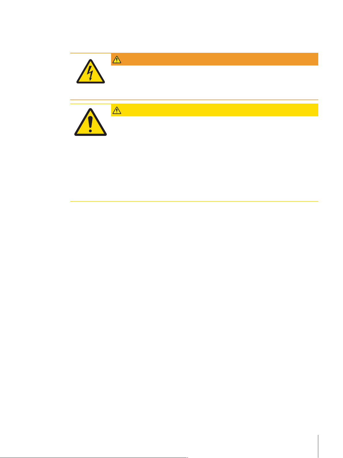
Signal words
WARNING
for a hazardous situation with medium risk, possibly resulting in severe
injuries or death if not avoided.
CAUTION
Attention
Note
for a hazardous situation with low risk, resulting in damage to the device
or the property or in loss of data or minor or medium injuries if not
avoided.
(no symbol)
for important information about the product.
(no symbol)
for useful information about the product.
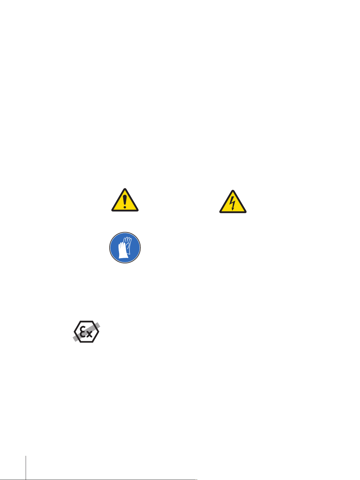
Warning symbols
General hazard Electrical shock
Mandatory signs
Gloves must be worn
2.2 Product safety information
Intended use
Your balance is used for weighing. Use the balance exclusively for this purpose. Any other type of use and
operation beyond the limits of technical specifications without written consent from Mettler-Toledo GmbH, is
considered as not intended.
It is not permitted to use the instrument in explosive atmosphere of gases, steam, fog, dust
and flammable dust (hazardous environments).
General safety information
This balance complies with current industry standards and the recognized safety regulations; however, it
can constitute a hazard in use. Do not open the balance housing: The balance contains no user-serviceable
parts. In the event of problems, please contact a METTLER TOLEDO representative.
Always operate and use your instrument only in accordance with the instructions contained in this manual.
The instructions for setting up your new instrument must be strictly observed.
If the instrument is not used according to these Operating Instructions, protection of the instrument
may be impaired and METTLER TOLEDO assumes no liability.
Staff safety
These operating instructions must be read and understood before using the balance. These operating
instructions must be retained for future reference.
Safety Information8 Analytical Balances
Page 11
The balance must not be altered or modified in any way. Only use METTLER TOLEDO original spare parts
and accessories.
Safety notes
WARNING
Risk of electric shock
Use only the original universal AC adapter delivered with your balance, and check that the
voltage printed on it is the same as your local power supply voltage. Only plug the
adapter into a socket which is grounded.
CAUTION
Damage to the balance
1 Only use indoors in dry locations.
2 Do not use pointed objects to operate the touch screen!
The balance is of a very sturdy design, but is still a precision instrument. It must be
handled with care.
3 Do not open the balance:
The balance contains no user-serviceable parts. In the event of problems, please
contact a METTLER TOLEDO representative.
4 Only use METTLER TOLEDO original accessories and peripheral devices for the
balance.
These are specifically designed for the balance.
Safety Information 9Analytical Balances
Page 12
3 Design and Function
1
2
3
4
5
7
6
8
9
10
11
12
13
w
ww.mt
.com
XSE204
MET
T
L
E
R TO
L
E
DO
19
20
18
17
1615
14
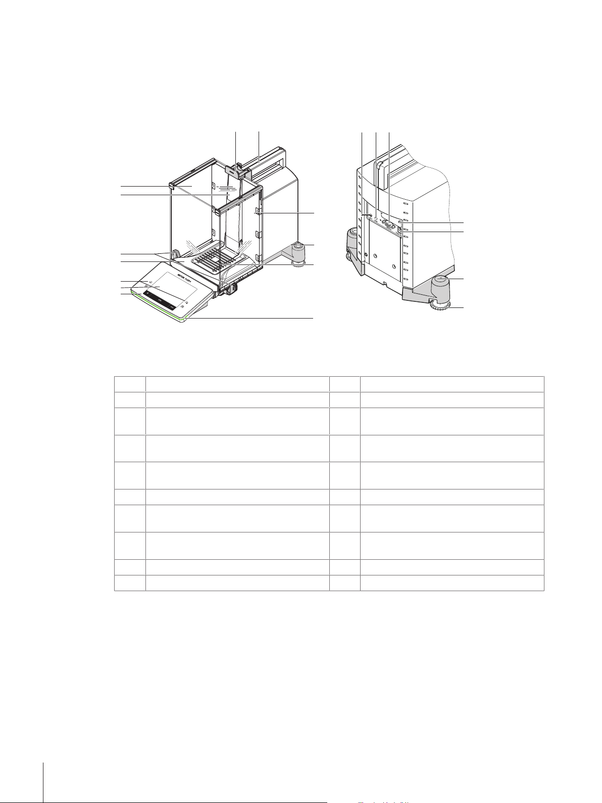
3.1 Overview
3.1.1 Balance
Legend
Terminal
1
Operating keys
3
Handle for operating the draft shield side
5
Display (“Touch screen”)
2
Drip tray
4
Type designation
6
doors
Glass draft shield
7
Handle for operation of the top draft shield
8
door
Guide for top draft shield door and transport
9
Removable clips for feeding cables or tubes
10
handle
Level indicator/Level sensor
11
StatusLight
13
SmartGrid weighing pan
12
Aux 1 (connection for "ErgoSens", hand or
14
foot switch)
Aux 2 (connection for "ErgoSens", hand or
15
RS232C serial interface
16
foot switch)
Slot for second interface (optional)
17
Fastening point for anti-theft device
19
Socket for AC adapter
18
Foot screw
20
Design and Function10 Analytical Balances
Page 13

3.1.2 Terminal
8
7
5
6
1
2
3
4
Key assignments and terminal connection.
1
2
Designation Explanation
Home This key is used to return to the user profile from any menu level in
any application. All changes made and confirmed up to this point
are automatically stored.
Select application This key is used to select a required application.
3
Configuration For displaying menus for the configuration of a current application.
The application can be adjusted to a specific task via numerous
settings.
4
Print This key is used to transfer data via the interface, e.g. to a printer.
Other devices, e.g. a PC can also be connected. The data to be
transferred can be freely defined.
5
On/Off For switching the balance on and off (standby mode).
Note
It is recommended not to disconnect the balance from the power
supply unless it is not used for an extended period.
6
Tare This key is used to tare the balance manually (only necessary for
normal weighings). When the balance has been tared, the Net
symbol is displayed to indicate that all displayed weights are net.
7
Zeroing This key is used for setting a new zero point manually (only
required if the balance is used for normal weighings).
8
StatusLight Indicates the current balance status. The status light shows that the
balance is ready to use.
Design and Function 11Analytical Balances
Page 14
1 22
System connection (terminal cable)
6
7
8
5
4
1 2 3
9
1
3.2 User interface
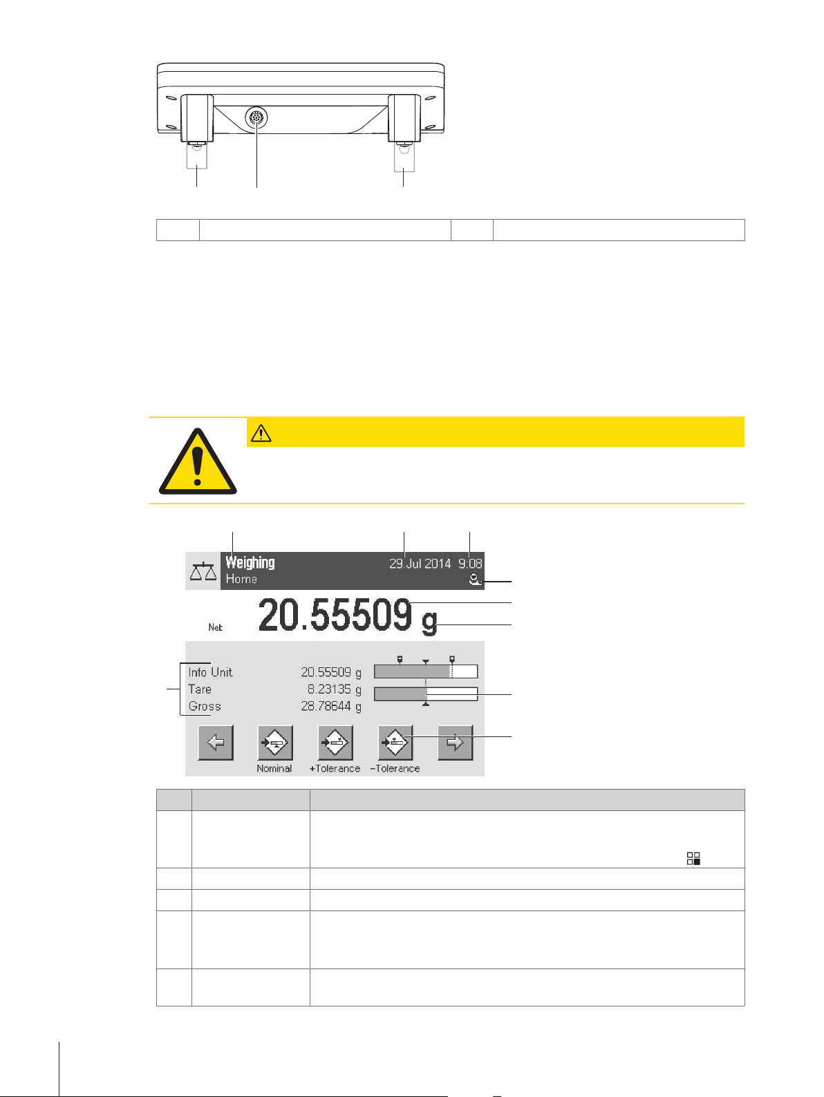
3.2.1 Display
The illuminated, color display of the terminal is a touch screen, i.e. a touch-sensitive screen. It can be used
for displaying data, entering settings and selecting functions by tapping the screen.
Note
Depending on country-specific requirements, non-calibrated decimal places are highlighted on approved
balances.
Height adjustable feet
2
CAUTION
Do not touch the touch screen with pointed or sharp objects!
This may damage the touch screen.
Designation Explanation
Application name Select application.
1
Date The date can be changed by tapping this zone.
2
Time The time can be changed by tapping this zone.
3
Status icons These status icons indicate special balance statuses (e.g. service due,
4
Weight value Tapping the weight displays a window showing the result in a large format.
5
Design and Function12 Analytical Balances
The application menu can be selected by touching this zone. The application
can be selected here. This menu can also be displayed by pressing [
].
adjustment required, battery replacement, out of level).
If you tap the icon, the function is explained.
This is useful for reading a weight from a certain distance.
Page 15
Weighing unit The required weighing unit can be changed by tapping the weighing unit, e.g.
1
2
3
6
from mg to g.
SmartTrac SmartTrac is a graphic weighing-in aid, which shows at a glance an already
7
used and still available weighing range.
Function keys
8
Information fields
9
This area is reserved for Function Keys enabling direct access to frequently
required functions and application settings. If more than 5 function keys are
activated, these can be selected with the arrow keys.
This area is used for displaying additional information (information fields)
relating to an active application. Tapping the information field enables
Information fields and Function Keys to be displayed directly via menu
selection. The leveling assistant can also be started.
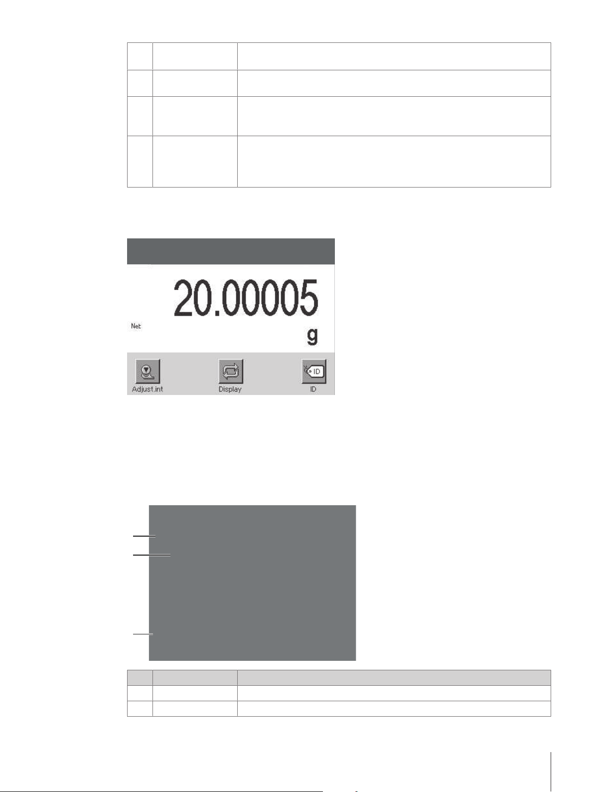
Large display
By pressing the function key [Display], the weighing result can be displayed larger and still allow the use of
the terminal function keys.
Screen saver
If the balance is not used for 15 minutes, the display is automatically dimmed and the pixels are inverted
about every 15 seconds. When the balance is used again (e.g. load weight, press key), the display returns
to a normal state.
3.2.2 Input dialog boxes
The keyboard dialog box is used to enter characters such as letters, numbers and special characters.
Designation Explanation
Data field Displays (entered) alphanumeric and numeric characters.
1
Keyboard Data input area
2
Design and Function 13Analytical Balances
Page 16
Selection Select various keyboard layouts.
1
2
3
3
1 Enter the designation.
2 Confirm with [OK].
3.2.3 Firmware
The firmware controls all balance functions. It enables the balance to be adjusted to a specific working
environment.
The firmware is divided as follows:
• System settings
• User-specific settings
• Applications
• Application-specific settings
Note
A displayed menu can be left at any time by repressing the same menu key.
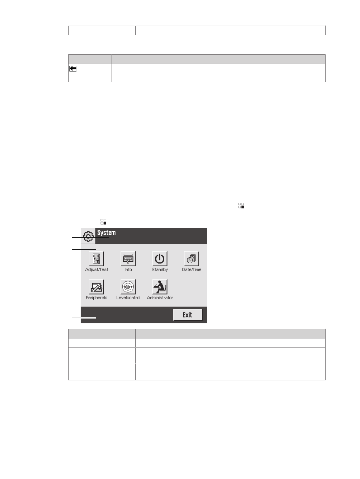
3.2.3.1 System settings
System settings (e.g. settings for peripheral devices) are independent of the applications and apply to the
entire weighing system. System settings can be displayed by pressing [
button.
Navigation: [
] > System
Function
Delete last character
Tap once to place the cursor at the end of the data field.
] and subsequently the [System]
Designation Explanation
Title bar The title bar displays elements for user orientation and information.
1
Contents area The contents area is the main work area for menus and applications. The
2
contents depend on the specific application or initiated action.
Action bar The action bar contains action buttons for performing specific actions required
3
in the active dialog box and are available (e.g. [Exit], [STD], [C], [OK]).
1 Settings can be changed by tapping the respective button.
3.2.3.2 User-specific settings
Design and Function14 Analytical Balances
2 To leave the settings, tap [Exit].
These settings can be used to adjust the balance to suit the tasks and work techniques of user.
Page 17
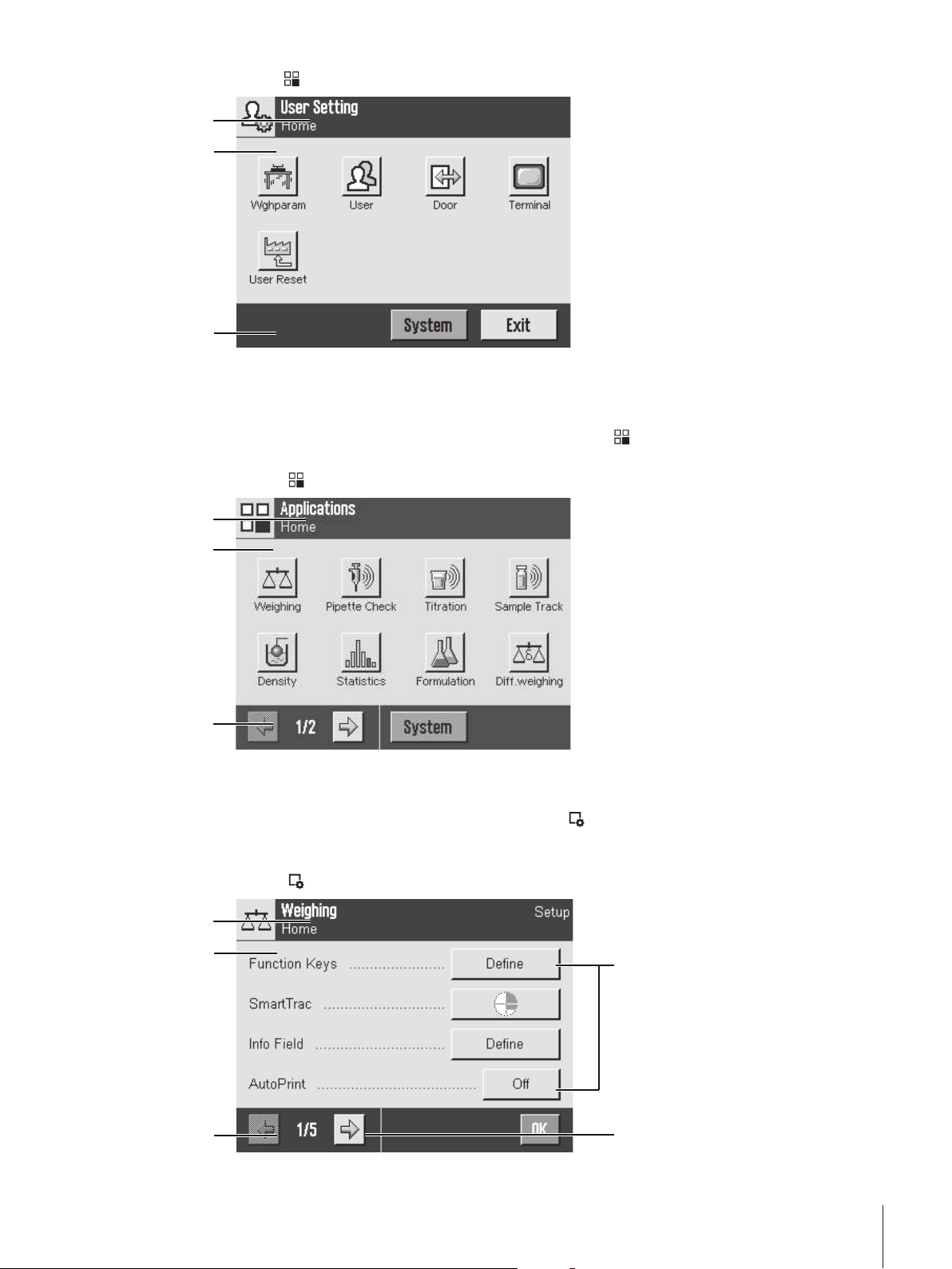
Navigation:[
1
2
3
1
2
3
5
4
1
2
3
] > [System] > [User Setting]
Applications
Applications are firmware modules for performing specific weighing tasks. The balance is delivered with
various applications pre-installed. After switching on the balance, the last active user profile and last used
application are loaded. The applications are available under the [
standard applications are provided in the respective sections.
Navigation: [
]
] key. Instructions for working with
Application-specific settings
These settings can be used to adjust the applications to suit specific requirements. The available setting
options depend on the selected application. Pressing the [
for a currently active application. Information on the individual setting options is provided in the section
relating to the respective application.
Navigation: [
]
] key opens the multipage menu with settings
Design and Function 15Analytical Balances
Page 18
Designation Explanation
Title bar The title bar displays elements for user orientation and information.
1
Contents area The contents area is the main work area for menus and applications. The
2
Action bar The action bar contains action buttons for performing specific actions required
3
Button
4
Arrow The arrow buttons are used to page forward or back.
5
1 Settings can be changed by tapping the respective button.
2 Confirm with [OK].
3 To leave the settings, select [Exit].
4 To change the system settings, tap [System].
3.2.4 Security system
The balance has a comprehensive security system with which individual access rights can be defined at
administrator and user level. Access to protected menu areas requires the entry of an identification (ID) and
a password. On delivery of the balance, only the [Administrator] settings in the system settings are
protected.
When an ID and password protected menu area is selected, an alphanumeric keyboard is initially displayed
for entry of the ID.
contents depend on the specific application or initiated action.
in the active dialog box and are available (e.g. [Exit], [STD], [C], [OK]).
Edit/Select settings (e.g. [Define], [On], [Off]). The contents depend on the
application.
CAUTION
Remember IDs and passwords!
Protected menu areas cannot be accessed without ID or password.
− Note IDs and passwords and keep them in a safe place.
1 Enter your ID.
- Case sensitive, tap the [a...z] and [A...Z] button to switch between upper and lower case.
- To enter numbers, tap the [0...9] button.
- Incorrect entries can be deleted character by character with the arrow key
Note
Entry can be interrupted at any time by tapping [C].
2 After entering the full ID, tap [OK].
ð A further dialog box is displayed for entering the password.
3 Enter the password (for security reasons, this is displayed with asterisks instead of plain text) and
confirm with [OK].
ð If the ID and password are correct, the selected menu area is displayed or the required action initiated. If
these are incorrect, an error message is displayed with a request to enter them again.
.
Design and Function16 Analytical Balances
Page 19

4 Installation and Putting into Operation
2
1
3
4
5
4.1 Unpacking
Open the balance packaging. Check the balance for transport damage. Immediately inform a METTLER
TOLEDO representative in the event of complaints or missing accessories.
Note
Retain all parts of the packaging. This packaging offers the best possible protection for transporting the
balance.
− Use the lifting strap to lift the balance out of the packaging box.
1 Remove the lifting strap (1).
2 Remove the top packaging (2).
1 Remove the operating instructions (3).
2 Remove the set with AC adapter (4), power supply cable,
drip tray, SmartGrid, SmartGrid cover, SmartPrep single-use
funnel and ErgoClip "Basket" (basket for small weighing
objects).
3 Remove the set with draft shield doors (5) and terminal
support.
Installation and Putting into Operation 17Analytical Balances
Page 20

1 Carefully remove the terminal (6) from the bottom
6
7
6
8
packaging.
2 Remove the protective cover.
Note
Since the terminal is connected to the balance with a cable,
only withdraw the balance slightly from the packaging in order
to remove the protective cover.
1 Place the terminal (6) at the front of the balance.
2 Hold the balance (7) by the guide or handle. Hold the
terminal firmly with the other hand. Pull out both
components together from the bottom packaging (8).
1 Place the balance with the terminal at the site of use.
2 Remove the cover from the balance.
3 Remove the transport protection (9) of the weighing pan
support.
4.2 Scope of delivery
Check the delivery for completeness. The following accessories are part of the standard equipment of the
balance:
• Balance with terminal
– RS232C interface
– Slot for second interface (optional)
– Feedthroughs for below-the-balance weighing and for antitheft device
• Set with draft-shield doors and terminal support
• SmartGrid
• SmartGrid cover, chromium-nickel steel
• SmartPrep single-use funnel (2 pieces)
Installation and Putting into Operation18 Analytical Balances
Page 21
• Drip tray
2
1
• AC adapter with country-specific power cable
• Protective cover for the terminal
• Cleaning brush
• ErgoClip "Basket" (basket for small weighing objects)
• Production certificate
• CE declaration of conformity
• Operating instructions or Quick Guide; printed or on CD-ROM, depending on country of use
4.3 Selecting the location
An optimal location will ensure accurate and reliable operation of the balance. The surface must be able to
safely take the weight of the balance when fully loaded. The following local conditions must be observed:
Note
If the balance is not horizontal at the outset, it must be leveled during commissioning.
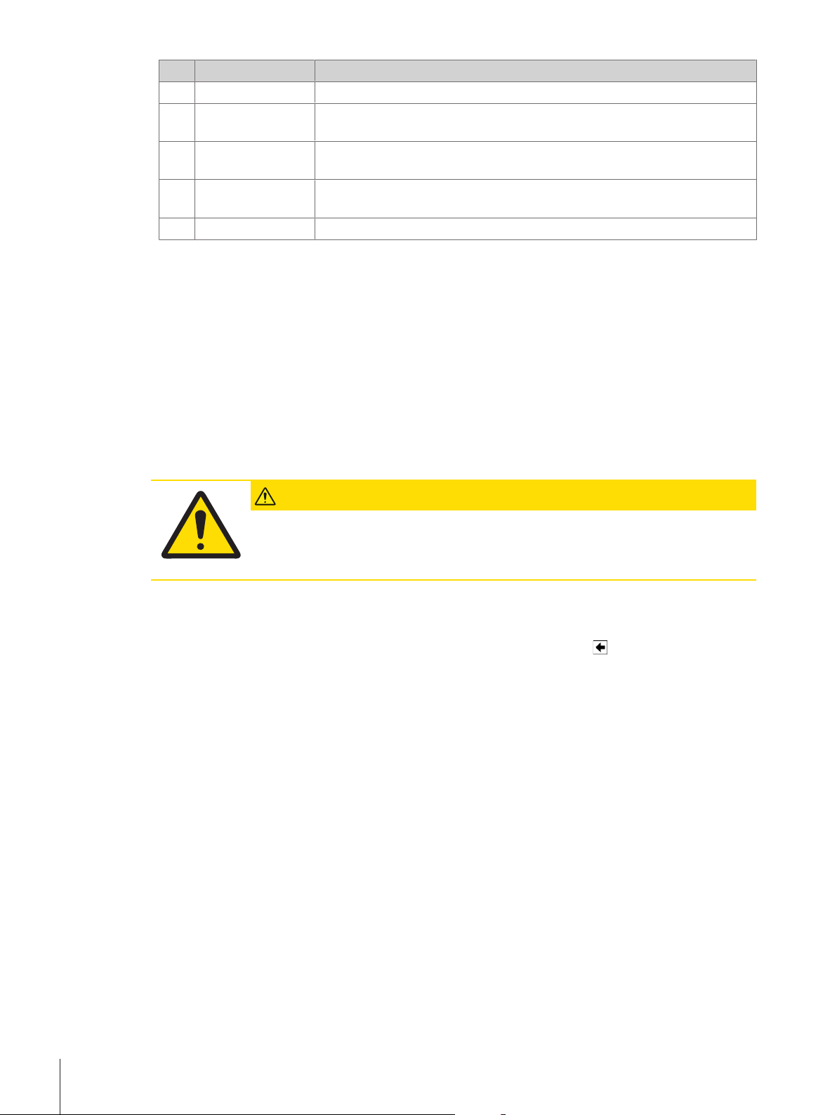
• The balance must only be used indoors and up to a
maximum altitude of 4,000 m above sea level.
• Before switching on the balance, wait until all parts are at
room temperature (+5 to 40°C).
The humidity must be between 10% and 80% noncondensing.
• The power plug must be accessible at all times.
• Firm, horizontal and vibration-free location.
• Avoid direct sunlight.
• No excessive temperature fluctuations.
• No strong drafts.
Further information can by found in Weighing the Right Way.
4.4 Assembling the balance
1 Remove the transport protection (1).
2 Insert the drip tray (2).
Insert the tray from the front above the bottom plate up to the
partition.
Installation and Putting into Operation 19Analytical Balances
Page 22
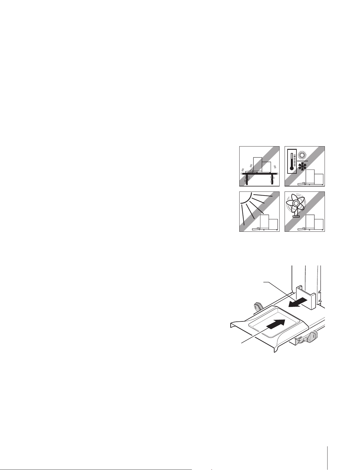
1 Insert the SmartGrid from the front.
2
1
1
2
2 Check that the SmartGrid (1) (2) is correctly hooked in on
both sides.
1 Insert the top draft shield door (1) at an angle (slightly
below 30 degrees) into the rear guide.
2 Carefully fold the draft shield door (2) downwards, see
figure.
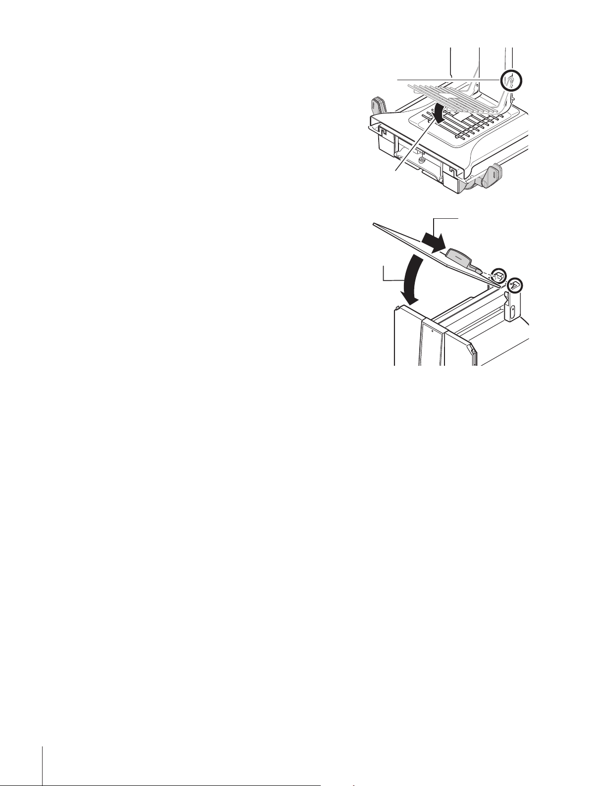
§ The handles (A) must be folded outwards to mount the side draft shield doors.
1 Mount the draft shield side doors according to the following instructions, see figure below.
2 Mount the side doors at an angle of about 30° in the 2 openings, see following figure.
3 Check that the side doors are correctly mounted as described.
4 Mount the side door so that it clicks in place in the balance.
The side door will move easily when correctly mounted.
5 Fold the handle of the side draft shield door inwards.
6 Mount the second draft shield side door. The procedure is identical.
7 Move the side doors fully back.
Installation and Putting into Operation20 Analytical Balances
Page 23
2
A
A
4
3
1
1 Fit the front draft shield glass (2).
1
2
Insert the glass at an angle into the bottom of the balance at
the front until the two hooks of the front draft shield glass
rest on the rollers (1).
2 Move the front draft shield glass upwards until it engages.
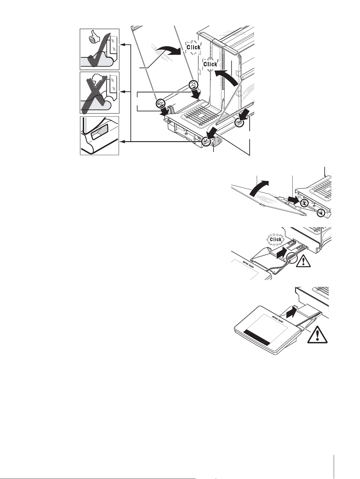
1 Insert the terminal support.
2 Place the cable in the guide of the terminal support.
3 Insert the terminal support into the opening in the front draft
shield glass.
ð The terminal support must engage with a click.
1 Mount the terminal.
2 Place the terminal in the center of the support.
3 Push the terminal against the balance until it folds down
easily at the front of the terminal support.
4 Insert the cable into the balance.
Attention
The balance and terminal are not connected by the terminal support! Always hold the balance and terminal
firmly during transport.
Note
The Terminal cable is of sufficient length to allow repositioning of the terminal in the area around the
balance.
Installation and Putting into Operation 21Analytical Balances
Page 24
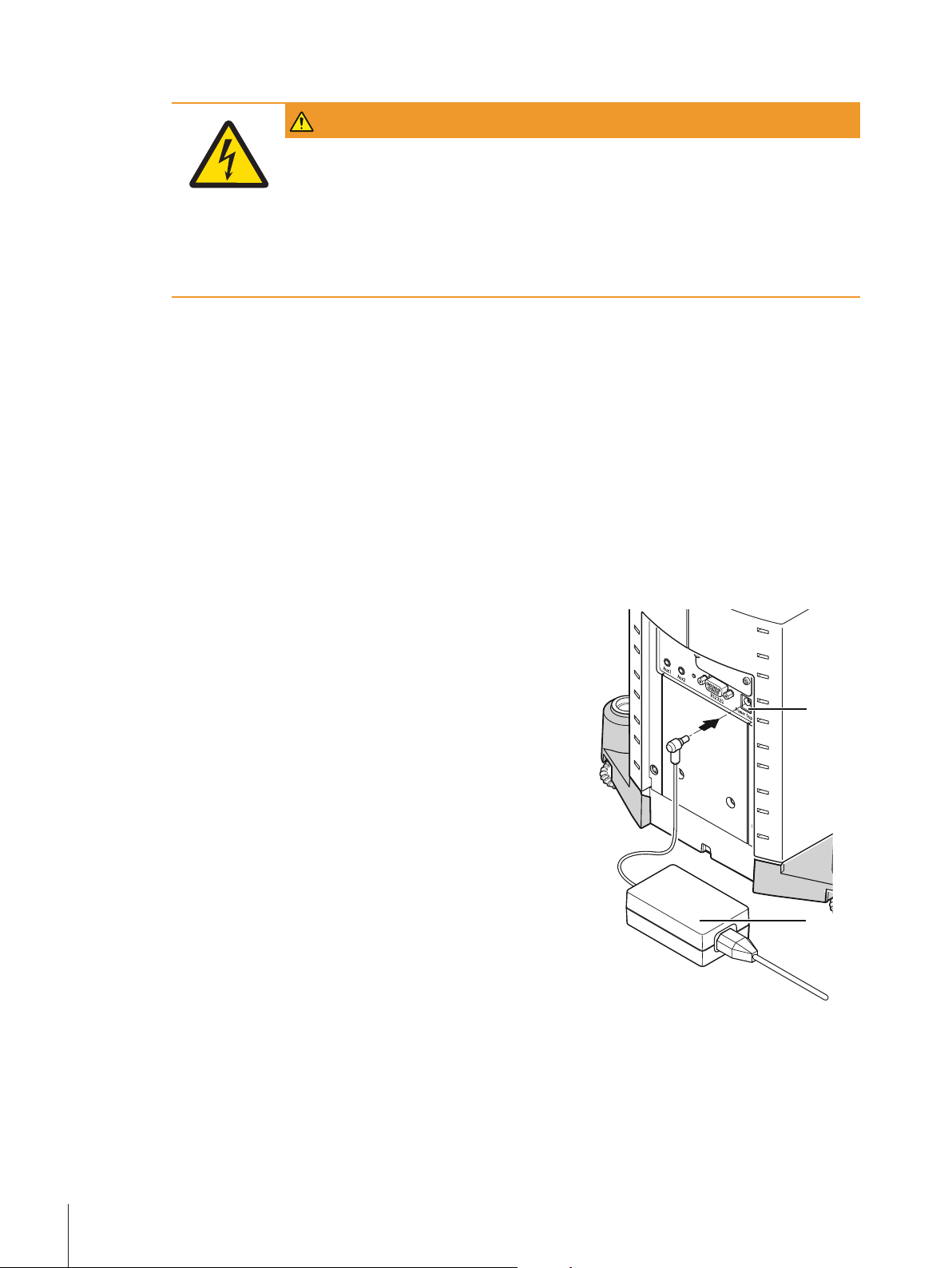
4.5 Connecting the balance
2
1
WARNING
Risk of electric shock
1 To connect the balance, only use the supplied three-core power cable with equipment
grounding conductor.
2 Only connect the balance to a three-pin power socket with earthing contact.
3 Only standardized extension cable with equipment grounding conductor must be used
for operation of the balance.
4 Intentional disconnection of the equipment grounding conductor is forbidden.
The balance is supplied with an AC adapter and country-specific power cable. The AC adapter is suitable for
use with the following voltage range:
100 – 240 VAC, 50/60Hz.
Attention
• Check whether your local power supply falls within this range. If this is not the case, under no circum-
stances connect the AC adapter to the power supply, but contact a METTLER TOLEDO representative.
• The power plug must be accessible at all times.
• Prior to use, check the power cable for damage.
• Route the cable in such a way that it cannot be damaged or cause a hindrance when working.
• Ensure that no liquid comes into contact with the AC adapter.
§ Balance and terminal are at the final location.
1 Connect the AC adapter (1) to the connection socket (2) at
the rear of the balance.
2 Connect the AC adapter (1) to the power supply.
ð The balance performs a self-test after connection to the
power supply and is then ready to use.
Installation and Putting into Operation22 Analytical Balances
Page 25
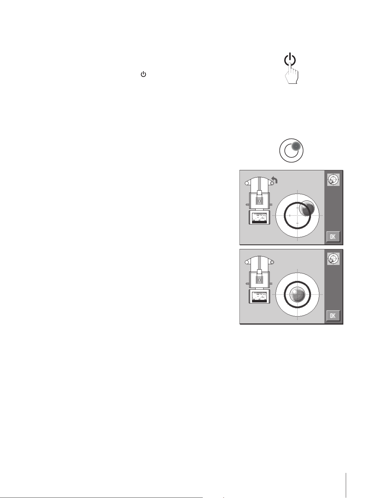
4.6 Setting up the balance
Switching on the balance
§ Balance is connected to the power supply.
§ Terminal and balance are interconnected.
− To switch on, press [
ð Display appears.
ð Balance is ready to use.
Leveling the balance
The balance has a built-in level sensor which permanently monitors correct horizontal alignment.
If the balance is not exactly level, a warning text is generated after switching on the balance with the request
to level the balance.
If the level sensor detects incorrect leveling, the status light at
the terminal shows red. A warning text is displayed and an
audible warning generated. A status icon also appears in the
top right corner of the display.
1 To start the leveling assistant, tap [LevelGuide] in the
warning message.
ð Window with level indicator is displayed in real-time.
2 Observe the level indicator on the screen.
ð The air bubble in the level indicator shows red with
incorrect alignment.
ð The leveling assistant indicates with red arrows the
direction in which the two foot screws at the rear of the
balance must be turned.
3 Turn the foot screw until the air bubble is located in the inner
circle of the level indicator.
ð The air bubble in the level indicator shows green with
correct alignment.
ð The status light at the terminal shows green.
4 Tap [OK].
ð A message recommending adjustment of the balance is
displayed.
5 Tap [Adjust.int] to adjust the balance.
].
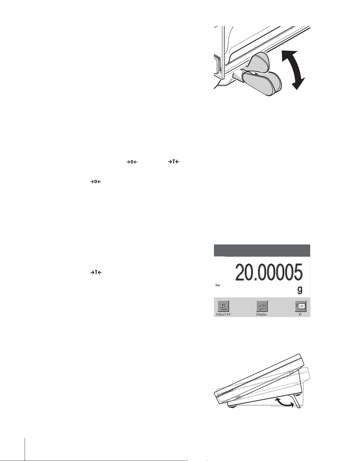
4.6.1 Handle for operation of the side draft shield doors
The draft shield of the balance can be adjusted to the ambient conditions, weighing method and material to
be weighed.
The position of the handles determines which draft shield doors (left, right or both) are opened.
Try out different combinations by moving the handles up or down. We recommend setting the glass draft
shield so that only the door required for loading is opened. The balance then operates faster due to less
disturbing air flows than with a fully open glass draft shield.
Note
It is recommended to make connections when the draft shield is closed.
Installation and Putting into Operation 23Analytical Balances
Page 26
1 Move the side door handle downwards.
2 Move the doors fully back.
4.6.2 Performing a simple weighing
After commissioning the new balance, the first weighing can be carried out. This will also familiarize you
with the operation of the balance.
To perform a simple weighing, only the keys in the lower part of the terminal are required. The balance has
separate keys for zeroing [
Zeroing
− Press [
ð Zeroing
After zeroing, all weights also the tare weight apply to this new zero point and the following apply: tare
weight = 0, net weight = gross weight = 0.
].
] and taring [ ].
Taring
Note
A negative weight is not permitted. An error message is generated. When the stability detector icon
extinguishes (small ring left of the weight display), the indication is stable. The weight is displayed.
§ If a weighing container is used, the balance must first be set
to zero.
1 Place the container on the balance.
2 Press [
ð The balance is tared.
ð The weight of the container is set as the new tare weight and
the previous tare (if available) is overwritten.
ð The Net display signals that all indicated weights are net
weights.
].
4.6.3 Setting the reading angle and positioning the terminal
4.6.3.1 Changing the reading angle
To change the reading angle, fold out both tilting feet.
Installation and Putting into Operation24 Analytical Balances
Page 27
4.6.3.2 Place terminal separately
w
ww.mt.com
XSE204
The terminal is connected to the balance with a cable. For ease of use, the terminal can be separated from
the balance and positioned in a different location.
Note
The cable can also be led out from the rear of the balance. If this is more convenient, contact a METTLER
TOLEDO representative who will help to modify the balance.
1 Switch off the balance with [
2 Carefully lift the terminal off the terminal support.
The terminal support can be left on the balance or removed.
3 Carefully remove the cable from the balance if this is
possible.
4 Position the balance in the required location.
5 Switch on the balance with [
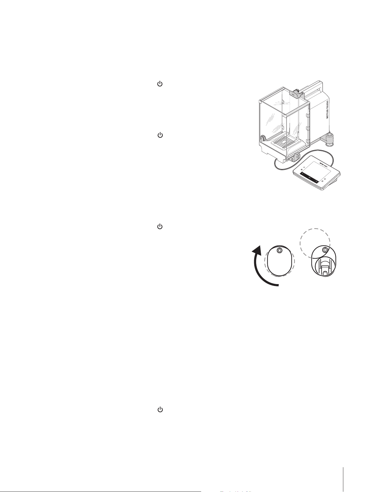
4.6.4 Below-the-balance weighing
].
].
The balance is provided with a hanger for below-the-balance weighing.
1 Switch off the balance with [
].
2 Disconnect the AC adapter cable at the rear of the balance.
3 Disconnect any interface cables.
4 Push all glass draft shield doors back.
5 Lift the terminal off the terminal support.
6 Disconnect the connecting cable.
7 Place the terminal at the side of the balance.
8 Move the balance over the edge of the table until the opening
is visible from below, see diagram on the left.
9 Slacken the screw until the cover plate can be turned to the
side and the hanger for weighing below the balance is easily
accessible.
10 Fix the cover plate in the new position with the screw, see
diagram on the right.
11 Move the balance back to its original position.
12 Connect the terminal cable.
13 Place the terminal in the terminal support.
14 Move all glass draft shield doors to the front.
15 Fix any interface cables.
16 Plug the AC adapter into the power supply socket at the rear
of the balance.
17 Switch on the balance with [
].
ð The balance is now ready for mounting the below-the-
balance weighing device.
Installation and Putting into Operation 25Analytical Balances
Page 28
4.6.5 Mounting the ErgoClips
ErgoClips allow simple weighing directly in tare containers.
The supplied ErgoClip or an optional ErgoClip must be mounted as described below.
Attention
Before mounting an ErgoClip, the balance must be switched off with the [
Important note!
If the balance is not switched off before mounting, the ProFACT function will not be activated.
Reason
The mounted ErgoClip causes the dead load tolerance range of the balance to be exceeded. As a result, the
balance does not activate ProFACT so as not to interrupt an assumed weighing process.
When the
cannot.
1 Switch off the balance with [
2 Remove the SmartGrid from the balance.
3 Snap the ErgoClip on to the SmartGrid.
4 Place the SmartGrid with mounted ErgoClip on the balance.
An optional "Flask" or "Tube" ErgoClip can be used.
5 Switch on the balance with [
status icon is displayed, this means that: "The balance needs to activate ProFACT", but
] key.
].
].
4.6.6 Fitting the SmartGrid cover
Note
For standard operation with conventional tare containers, we do not recommend using this weighing pan.
Its use may affect the stabilization time and degree of accuracy. The listed specifications are reached
without a SmartGrid cover.
CAUTION
Hand injuries
Take care when handling the SmartGrid cover, the corners and edges are extremely sharp!
− Gloves must be worn.
To fit the SmartGrid cover, remove the SmartGrid from the weighing chamber.
1 Remove the SmartGrid from the balance.
2 Gently press the SmartGrid cover on to the SmartGrid.
3 Place the SmartGrid with fitted SmartGrid cover on the
balance.
4.7 Transporting the balance
Observe the following instructions to transport your balance to a new location.
Installation and Putting into Operation26 Analytical Balances
Page 29
Switching off the balance
www.mt.com
XSE204
METTLER TOLEDO
www.mt.com
XSE204
2
1
3
4
5
6
78
1 Press and hold [
2 Disconnect the balance from the power supply.
3 Disconnect all interface cables.
] until Off appears in the display.
4.7.1 Transport over short distances
To move the balance over a short distance to a new location, follow the instructions below.
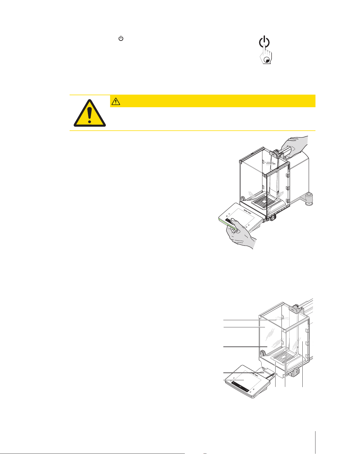
CAUTION
Damage to the balance
Never lift the balance by the glass draft shield as this can cause damage!
1 Hold the balance by the guide for the top draft shield door
with one hand.
2 Hold the terminal with the other hand.
Since the terminal is not permanently connected to the
balance, both the balance and terminal must always be held
with one hand.
3 Carefully lift the balance and carry it to its new location. See
[Selecting the location}19].
4.7.2 Transport over long distances
The complete original packaging must be used for transportation or shipment of the balance over long
distances or if it cannot be ensured that the balance will be transported upright.
Remove the following parts
1 Lift the terminal (1) out of the terminal support and place it
next to the support.
2 Remove the terminal support (2) from the balance.
3 Tilt the draft shield front glass (3) away from the balance.
4 Carefully move the draft shield side doors (4+5) towards the
respective handle and remove the side doors from the guide.
5 Lift the front of the top draft shield door (6) and remove it
from the guide.
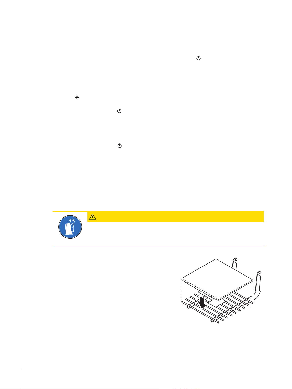
6 Carefully lift the front of the SmartGrid (7) and lift it out of the
guide.
7 Remove the drip tray (8).
Installation and Putting into Operation 27Analytical Balances
Page 30
Pack the draft shield glass panels and terminal support (Item 2-6).
− Place these parts in the compartments provided in the
original packaging.
Note
It is recommended to place paper between the side draft
shield glass panels.
Pack the AC adapter, power cord and individual components (Item 7+8)
1 Place the AC adapter and power cord in the packaging.
2 Place the drip tray (8) upside down in the packaging.
3 Place the SmartGrid (7) upside down on the drip tray.
4 Place the ErgoClip "Basket" in the packaging.
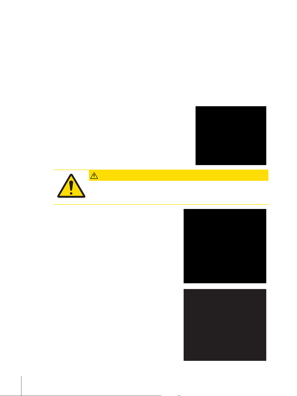
CAUTION
Damage to the balance
Follow the instructions below to avoid damaging the balance when placing in the
packaging.
1 Slide the transport protection along the weighing pan guide.
2 Move the guide of the top draft shield door to the front.
3 Move the handles for the draft shield side doors upwards
and slide the doors to the front.
Note
The protective covers supplied with the balance and terminal
can be used for packing. These are not shown in the diagrams
in order to illustrate how the individual components must be
positioned. The use of these protective covers is recommended.
1 Place the terminal on the balance, see diagram.
2 Carefully place the balance in the bottom packaging.
Installation and Putting into Operation28 Analytical Balances
Page 31

− Remove the terminal and place it in front of the packaging
on the table.
− Place the packaging set with the draft shield glass panels in
the packaging, see diagram.
1 Place the set with the AC adapter in front of the set with draft
shield glass panels.
2 Place the terminal in the packaging as illustrated.
1 Place the top packaging in position.
ð Ensure that the packaging is correctly positioned.
2 Place the lifting strap around both parts of the packaging,
see diagram.
3 Tighten the strap around the packaging.
ð Lift the packed balance by the lifting strap and place in
the transport box.
Installation and Putting into Operation 29Analytical Balances
Page 32

5 System Settings
System
Adjust/Test
ProFACT On
ProFACT
ProFACT
Weekdays
Monday x
Tuesday x
Wednesday x
Thursday x
Friday x
Saturday x
Sunday x
Time 1 9:00
ProFACT
Time
Time 2 Off
ProFACT
Time
Time 3 Off
ProFACT
Time
Temp.Criterion 1 Kelvin
Protocol Trigger On
Autom. ext. Adjust. Off
Autom. ext. Adjust.
Autom. ext. Adjust.
Weekdays
Monday x
Tuesday Wednesday Thursday Friday Saturday Sunday Autom. ext. Test Off
Autom. ext. Test
Weekdays
Monday x
Tuesday Wednesday Thursday Friday Saturday Sunday Time 9:00
Time
Test History
Adj. History
Adj. History Selection
Selection
Manual adjust. x
Temperature x
Time Adjust. x
Display Datasets Last 50
Protocol
Date/Time x
User x
Balance Type x
SNR x
SW-Version Balance ID Weight ID Certificate No.
Navigation: [
] > [System]
This section describes the procedure for adapting the weighing system to suit specific requirements. The
system settings apply to the entire weighing system and therefore to all applications.
− The system settings can be displayed by pressing [
] and subsequently the [System] button.
ð The [System] window is displayed.
Printing all System settings
§ A printer is connected and activated.
− If you are in the root of the System settings, press [
].
Note
• The detail of the protocol depends on the point at which printout is activated in the system settings.
When [
] is pressed in the uppermost level of the system settings, all system settings are recorded. If
printing is started in the [Peripherals] submenu for example, only the settings for the peripheral devices
are recorded.
• The Test/Adj. Weights, Test Sequences and Tasks submenus in the [Adjust/Test] menu must be
printed separately.
Example: Printout
System Settings30 Analytical Balances
System settings overview
Designation Explanation
Adjust/Test
Info
Standby
Settings for adjustment and test functions for verification of
adjustments.
Display/printing of balance information.
Settings for the standby mode.
Page 33

Date/Time
Peripherals
Entry of date and time and selection of required display
formats.
Configuration of interface for various peripheral devices.
Option
Levelcontrol
User Setting
Administrator
Menu structure
Main menu Submenu Further information
Adjust/Test Test/Adj. Weights See [Settings for adjustments and
Test Sequences See [Test sequences}35]
Tasks See [Tasks}43]
ProFACT / int. Adj. See [ProFACT/int.
Autom. ext. Adjust. See [Automatic adjustment with an
Autom. ext. Test See [Testing the adjustment with an
WeightLink See [Test with WeightLink}46]
Test History See [Test history}47]
Protocol See [Protocol – Definition of
Info Balance ID See [Info}48]
Info
Standby Standby See [Standby}49]
Date/Time Date Format See [Date/Time}49]
Date
Time Format
Time
Peripherals Printer See [Peripherals}50]
Host
LabX
LabX Controlled Device
Secondary Display
Bar Code
RFID / Quantos
Label Printer
Configuration of the optional interface.
Settings for the built-in level sensor.
Configuration of user settings.
Configuration of the security system of the balance with
allocation of access rights and passwords for weighing
functions and menus.
tests}33]
Adjustment}44]
external test weight}45]
external test weight }46]
adjustment and test reports }48]
System Settings 31Analytical Balances
Page 34

Option DHCP See [Option}52]
IP-Address
Subnet Mask
Standard Gateway
Domain Name Server
Hostname
Levelcontrol Off See [Level sensor}52]
Levelcontrol
User Setting Wghparam See [User settings}53]
User
Terminal
User Reset
Administrator Protected Area: Enter
Administrator ID.
Protected Area: Enter Admin.
Password.
Administrator ID
Administrator Password
Master Reset
Home Rights
Passw. Change Date
See [Administrator}61]
5.1 Adjustment/Test
Introduction for adjustment and tests
This section applies to the configuration of the balance for carrying out adjustments and tests.
§ The balance is assembled and installed as stated in the operating instructions.
§ The balance is leveled.
1 Connect the printer to printout settings or reports.
2 Activate the printer as an output device in the peripheral device settings.
Principles for carrying out adjustments and tests
Balances play a decisive role in research, development, quality assurance and production. Weighing errors
cost time and money and non-compliance with legal requirements can be detrimental to health. Good
Weighing Practice™ (GWP®) is the science based global weighing standard for the efficient life cycle
management of weighing systems. The risk-based approach allows you to improve control of your whole
measuring process, which in turn helps to avoid costly out of specification results. Our Feasible Cost
Savings Optimized routine testing based on your risk management ensures consistently good quality in
critical applications. Additionally, a sound testing scheme saves costs by eliminating unnecessary tests in
lower risk processes.
Test Manager was specially developed, as part of our balance firmware, to simplify routine tests. In
combination with GWP® Verification, efficient balance testing is ensured and specific audit requirements
can be fulfilled more easily.
u www.mt.com/GWPVerification
System Settings32 Analytical Balances
Page 35

Test Manager
Test Manager is a collection of security functions for the balance. These individually programmable
functions help to maintain measuring accuracy via e.g. routine testing of the balance with external test
weights. By providing active support with respect to test requests and predefined guided sequences will
ensure that outstanding tests are not forgotten and complex tasks such as repeatability tests can be carried
out easily.
Additional functions were developed to prevent measuring errors. These are, e.g. temperature sensors that
can register possible temperature changes in the measuring cell and initiate adjustment by using internal
weights which facilitate and maintain consistent accuracy.
The flexibility and customization of the test manager results in user guidance and appropriate messages,
while performing specific operations, followed by complete records and documentation via printout or in
conjunction with PC software.
The configuration process
In order to prepare the balance for a routine test and adjustment, a straightforward 3-stage process is
required:
1 Register the test weights.
ð Information relating to all test weights is stored in a balance database.
2 Define the test sequence.
ð Describes the type of test (method) and the test weight and tolerance to be carried out.
3 Carry out the test sequence.
ð The task defines when and how the test sequence must be started and carried out.
Documentation and storage
To ensure the traceability of adjustments and tests, it is important to print the settings and periodically the
results of the test history.
The results are stored in the test history up to a maximum of 120 entries. When this limit is reached, the
oldest results are overwritten.
Each time the test sequence is changed, the version number is increased and displayed in the right top
corner of the display. It is recommended to print and file each new version in a folder.
A complete list of individual settings can be printed by pressing the [
open.
] key while the respective menu is
Settings for adjustments and tests
Navigation: [
This section describes all menu options and parameters relating to adjustment and testing of the balance.
For carrying out adjustments and tests, see [Balance adjustment and testing}87].
The arrow buttons can be used to page forward or back to a menu page.
You can define the following parameters:
Menu item Explanation Further information
Test/Adj.
Weights
Test Sequences
Tasks
ProFACT / int.
Adj.
Autom. ext.
Adjust.
Autom. ext.
Test
] > [System] > [Adjust/Test]
Define the test weights and parameters for
adjustment. Procedures for testing or adjustment.
Defines the parameters of a test sequence for
testing and behavior of the balance.
Defines the task of a test sequence.
Fully automatic internal balance adjustment.
Automatic external adjustment.
Adjustment testing.
See [Test/Adjustment - weight
settings }34]
See [Test sequences}35]
See [Tasks}43]
See [ProFACT/int.
Adjustment}44]
See [Adjustment with external test
weight}88]
See [Testing the adjustment with an
external test weight }46]
System Settings 33Analytical Balances
Page 36

WeightLink Activates/deactivates the WeightLink weight
verification system.
Test History
Protocol
Defines the settings for the test history.
Defines the settings for the adjustment and test
protocols.
5.1.1 Test/Adjustment - weight settings
See [Test with WeightLink}46]
See [Test history}47]
See [Protocol – Definition of
adjustment and test reports }48]
Navigation: [
This menu can be used to enter the designations or numbers of the certificate supplied with the respective
test weight. This enables each external test weight to be clearly assigned to a specific certificate. Up to 12
external test weights can be configured. These test weights are used to carry out external tests and
adjustments.
1 Tap [Define].
ð Test/Adj. Weights window is displayed.
2 Select an undefined weight or the name of the weight, the parameters of which are to be updated.
3 Tap [Define].
4 Change the settings and confirm with [OK].
ð The defined weights are available for selection in the test sequences.
Note
When the weight list is displayed, all parameters of the 12 test weights can be printed out with [
] > [System] > [Adjust/Test] > Test/Adj. Weights
].
Test/Adj. Weight 1...Test/Adj. Weight12
You can define the following parameters:
Parameters Explanation Values
Name
Weight ID
Class
Certificate No.
Weight Set No.
Actual Value
Next Recalibration
* Factory setting
Defines a name for a test weight (max. 20 characters). Any
(Test/Adj. Weights)*
Defines the identification (ID) of the weight (max. 20
characters).
Defines the class of the weight.
Note
Own can be selected if no other class can be used.
Defines the certificate number of the external test weight used
(max. 20 characters).
Defines the identification number of the set of weights if the test
weight belongs to a set of weights (max. 20 characters).
Weight from the weight certificate. Irrespective of the type of
balance, the full value should be taken over without taking the
decimal places of the balance into account (e.g. 20.00124
g).
Note
Methods use the actual value; this is rounded to the maximum
decimal places of the balance and used for calculation.
Entry of the date of the next weight calibration.
Note
If no weight calibration is planned, the default value
(31.12.2099) should be maintained .
Any
E1* | E2 | F1 | F2 | M1
| M2 | M3 | ASTM1 |
ASTM2 | ASTM3 |
ASTM4 | ASTM5 |
ASTM6 | ASTM7 | Own
| ASTM0 | ASTM00 |
ASTM000
Any
Any
Weight
(0 g)*
DD.MM.YYYY
(31.12.2099)*
System Settings34 Analytical Balances
Page 37

5.1.2 Test sequences
Navigation: [
Test sequences define which test is carried out with which test weight. The user is guided through.
Note
The test should be carried out according to GWP® or another QM systems.
When Test Sequences is selected, a list of test sequences, the parameters of which can be adapted or
overwritten, appears.
Up to 12 test sequences can be defined.
Note
In the test sequence you define among others the type of the test (= Method) and the weights to be used for
this method. Before these weights can be selected, they have to be defined in [
Test] > Test/Adj. Weights.
§ The test weights are defined.
1 Tap [Define].
ð Test Sequences window appears.
2 Select an undefined or existing test sequence, for example Test Sequence 1 to be configured or
adapted.
3 Tap [Define].
ð Test Sequence window appears.
4 Enter the designations and parameters and confirm with [OK].
ð The test sequence is stored in the Test Sequence menu.
ð Each time a test sequence is stored, the version number is increased by 1. The version number is
shown at the top right of the display.
The arrow buttons can be used to page forward or back to a menu page.
Note
When the test sequence list is displayed, all parameters of the 12 test sequences can be printed with [
] > [System] > [Adjust/Test] > Test Sequences
] > [System] > [Adjust/
].
Configuration of test sequence parameters
Navigation: [
You can define the following parameters:
Parameters Explanation Values
Name
Preparation
Instructions
] > [System] > [Adjust/Test] > Test Sequences > Test Sequence 1
Defines a designation for a test sequence (max. 20
characters).
Note
Choose a comprehensible name to enable clear identification
and easy traceability.
Selection of preparatory instructions.
None = no preparatory instructions are displayed in the test
sequence.
This is normally used for test sequences requiring no user
actions, e.g. test sequences with the SERVICE method.
Standard = the following preparatory instructions are
displayed. These correspond to the typical SOP standard.
1 Clean the weighing pan.
2 Level the balance.
3 Switch on the printer.
4 Have the test weights ready.
5 Have the weight tweezers/fork ready.
Any
(Test Sequence 1)*
None* | Standard
System Settings 35Analytical Balances
Page 38

Method
Action if Failure
Instructions if
Failure
Code to
Unblock
Entry in GWP
History
* Factory setting
For more details about Method see [Method}36], and Action if Failure see [Action if failure}42]
Describes the type of test to be carried out and defines the
main purpose of a test sequence. The test weights and
respective tolerances to be used must be defined as part of the
method.
Defines how the balance should react if the test fails or is
aborted.
Defines the instructions.
This setting is independent of the parameters Action if Failure
and is displayed each time a test sequence fails.
None = the test sequence Name has failed.
Standard = the test sequence Name has failed.
The balance is outside the defined tolerances.
Contact a responsible person within your company or
METTLER TOLEDO service.
System release.
Note
If Action if Failure None is selected, a failed test sequence will
never block the balance.
Defines whether the test result is stored in the GWP history.
Yes = result of test sequence is stored.
No = result of test sequence is not stored.
Note
If 120 entries are exceeded, the oldest result is overwritten with
the newest result.
None | EC | RP1 |
RPT1 | SE1 | SE2 |
SERVICE | SET1 |
SET2
None | Warning |
Attempt
None* | Standard
Any
(Z)*
Yes | No*
5.1.2.1 Method
Navigation: [
A method describes the type of test to be carried out and defines the main purpose of a test sequence. The
test weights and respective tolerances to be used must be defined as part of the method. There are 8
different methods available.
You can define the following parameters:
Menu item Explanation Further information
None
EC
RP1
RPT1
SE1
SE2
SERVICE
SET1
] > [System] > [Adjust/Test] > Test Sequences > Test Sequence 1 > Method
No method has been selected.
Method for eccentric load test.
Method for repeatability test.
Method for repeatability test with tare weight.
Method for sensitivity test with one test weight.
Method for sensitivity test with two test weights.
Service method.
Method for sensitivity test with tare weight and
one test weight.
See [EC - eccentric load test
}37]
See [RP1 - repeatability test
}37]
See [RPT1 - repeatability test with
tare weight }38]
See [SE1 - sensitivity test with one
weight }39]
See [SE2 - sensitivity test with two
weights }40]
See [SERVICE - reminder}40]
See [SET1 - sensitivity test with
tare and one test weight }41]
System Settings36 Analytical Balances
Page 39

SET2
5.1.2.1.1 EC - eccentric load test
Method for sensitivity test with tare weight and two
test weights.
See [SET2 - sensitivity test with
tare and two test weights}41]
Navigation: [
The purpose of the EC method (eccentric load test) is to ensure that every eccentric load deviation is within
the necessary user SOP tolerances.
The method uses two test tolerances (method tolerances), s T1 and s T2, which are applied to the test
sequence result. They work exactly the same as the weight tolerances T1 and T2.
] > [System] > [Adjust/Test] > Test Sequences > Test Sequence 1 > Method > [EC]
Test Weight
Navigation: [
Test Weight
You can define the following parameters:
Parameters Explanation Values
Test/Adj.
Weight
Tolerances
] > [System] > [Adjust/Test] > Test Sequences > Test Sequence 1 > Method > [EC] >
Selects the predefined test weight.
Test/Adj. Weight 1 … Test/Adj. Weight12 = defined in Test/
Adj. Weights menu item.
It is recommended to set the test weight tolerances to 100%.
Because for this kind of test the test tolerance is relevant.
Test/Adj. Weight 1 |
Test/Adj. Weight 2 | ...
| Test/Adj. Weight12
Tolerance T1 | Name
T1 | Tolerance T2 |
Name T2
Tolerances for eccentric load deviation
Navigation: [
Test Weight > Tolerance for Eccentricity Dev.
You can define the following parameters:
Parameters Explanation Values
Tolerance EC
T1
Name EC T1
Tolerance EC
T2
Name EC T2
* Factory setting
] > [System] > [Adjust/Test] > Test Sequences > Test Sequence 1 > Method > [EC] >
Defines the tolerance EC T1 for the eccentric load deviation.
If the result tolerance (method tolerance) EC T1 is exceeded,
the eccentric load test is passed with a warning.
Defines a designation for EC T1 (max. 20 characters). Any
Defines the tolerance EC T2 for the eccentric load deviation.
If the result tolerance (method tolerance) T2 is exceeded, the
eccentric load test fails.
Defines a designation for EC T2 (max. 20 characters). Any
Any
(0.10 g)*
(Warn Limit)*
Any
(0.10 g)*
(Control Limit)*
5.1.2.1.2 RP1 - repeatability test
Navigation: [
The RP1 method calculates the mean and standard deviation (Symbol s) of a series of measurements with
a single test weight in order to determine the repeatability of the balance.
The method uses two result tolerances (method tolerances), s T1 and s T2, which are applied to the test
sequence result. They function similar to T1 and T2.
] > [System] > [Adjust/Test] > Test Sequences > Test Sequence 1 > Method > [RP1]
Test Weight
Navigation: [
Test Weight > Test/Adj. Weight
You can define the following parameters:
] > [System] > [Adjust/Test] > Test Sequences > Test Sequence 1 > Method > [RP1] >
System Settings 37Analytical Balances
Page 40

Parameters Explanation Values
Test/Adj.
Weight
Tolerances
Selects the predefined test weight.
Test/Adj. Weight 1 … Test/Adj. Weight12 = defined in Test/
Adj. Weights menu item.
It is recommended to set the test weight tolerances to 100%.
Because for this kind of test the test tolerance is relevant.
Test/Adj. Weight 1 |
Test/Adj. Weight 2 | ...
| Test/Adj. Weight12
Tolerance T1 | Name
T1 | Tolerance T2 |
Name T2
Tolerances (s) for repeatability test
Navigation: [
Test Weight > Tolerances (s)
You can define the following parameters:
Parameters Explanation Values
Tolerance s T1
Name s T1
Tolerance s T2
Name s T2
* Factory setting
] > [System] > [Adjust/Test] > Test Sequences > Test Sequence 1 > Method > [RP1] >
Defines the tolerance s T1 for the repeatability test.
If the tolerance s T1 is exceeded, the repeatability test is
passed with a warning.
Defines a designation for s T1 (max. 20 characters). Any
Define the tolerance s T2 for the repeatability test.
If the tolerance s T2 is exceeded, the repeatability test fails.
Defines a designation for s T2 (max. 20 characters). Any
Any
(0.000 g)*
(Warn Limit)*
Any
(0.000 g)*
(Control Limit)*
Number of Repetitions
Navigation: [
Test Weight > Number of Repetitions
You can define the following parameters:
Parameters Explanation Values
Number of
Repetitions
* Factory setting
5.1.2.1.3 RPT1 - repeatability test with tare weight
Navigation: [
The RPT1 method calculates the mean and standard deviation (Symbol s) of a series of measurements with
two test weights in order to determine the repeatability. In contrast to the RP1 method, a second test weight
is used to simulate the use of a tare container.
The method uses two test tolerances (method tolerances), s T1 and s T2, which are applied to the test
sequence result. They work exactly the same as the weight tolerances T1 and T2.
] > [System] > [Adjust/Test] > Test Sequences > Test Sequence 1 > Method > [RP1] >
Defines the number of weight measurements of a series. 2 … 15
] > [System] > [Adjust/Test] > Test Sequences > Test Sequence 1 > Method > [RPT1]
Tare Weight
Navigation: [
> Tare Weight > Test/Adj. Weight
You can define the following parameters:
Parameters Explanation Values
Tare Weight
] > [System] > [Adjust/Test] > Test Sequences > Test Sequence 1 > Method > [RPT1]
Selects the predefined test weight corresponding to the tare
container weight.
Test/Adj. Weight 1 … Test/Adj. Weight12 = defined in Test/
Adj. Weights menu item.
(10)*
Test/Adj. Weight 1 |
Test/Adj. Weight 2 |...
| Test/Adj. Weight12
System Settings38 Analytical Balances
Page 41

Tolerances
It is recommended to set the tare weight tolerances to 100%.
Tolerance T1 | Name
T1 | Tolerance T2 |
Name T2
Test Weight
Navigation: [
> Test Weight > Test/Adj. Weight
You can define the following parameters:
Parameters Explanation Values
Test/Adj.
Weight
Tolerances
] > [System] > [Adjust/Test] > Test Sequences > Test Sequence 1 > Method > [RPT1]
Selects the predefined test weight.
Test/Adj. Weight 1 … Test/Adj. Weight12 = defined in Test/
Adj. Weights menu item.
It is recommended to set the test weight tolerances to 100%.
Because for this kind of test the test tolerance is relevant.
Test/Adj. Weight 1 |
Test/Adj. Weight 2 | ...
| Test/Adj. Weight12
Tolerance T1 | Name
T1 | Tolerance T2 |
Name T2
Tolerances (s) for repeatability test
Navigation: [
> Test Weight > Tolerances (s)
You can define the following parameters:
Parameters Explanation Values
Tolerance s T1
Name s T1
Tolerance s T2
Name s T2
* Factory setting
] > [System] > [Adjust/Test] > Test Sequences > Test Sequence 1 > Method > [RPT1]
Defines the tolerance s T1 for the repeatability test.
If the tolerance s T1 is exceeded, the repeatability test is
passed with a warning.
Defines a designation for s T1 (max. 20 characters). Any
Define the tolerance s T2 for the repeatability test.
If the tolerance s T2 is exceeded, the repeatability test fails.
Defines a designation for s T2 (max. 20 characters). Any
Any
(0.000 g)*
(Warn Limit)*
Any
(0.000 g)*
(Control Limit)*
Number of Repetitions
Navigation: [
> Test Weight > Number of Repetitions
You can define the following parameters:
Parameters Explanation Values
Number of
Repetitions
* Factory setting
5.1.2.1.4 SE1 - sensitivity test with one weight
Navigation: [
The SE1 method tests the sensitivity of the balance with one test weight.
] > [System] > [Adjust/Test] > Test Sequences > Test Sequence 1 > Method > [RPT1]
Defines the number of weight measurements of a series. 2 … 15
] > [System] > [Adjust/Test] > Test Sequences > Test Sequence 1 > Method > [SE1]
Test Weight
Navigation: [
Test Weight > Test/Adj. Weight
You can define the following parameters:
] > [System] > [Adjust/Test] > Test Sequences > Test Sequence 1 > Method > [SE1] >
(10)*
System Settings 39Analytical Balances
Page 42

Parameters Explanation Values
Test/Adj.
Weight
Tolerances
5.1.2.1.5 SE2 - sensitivity test with two weights
Selects the predefined test weight.
Test/Adj. Weight 1 … Test/Adj. Weight12 = defined in Test/
Adj. Weights menu item.
The test tolerances are used for the sensitivity test.
Test/Adj. Weight 1 |
Test/Adj. Weight 2 | ...
| Test/Adj. Weight12
Tolerance T1 | Name
T1 | Tolerance T2 |
Name T2
Navigation: [
The SE2 method tests the sensitivity of the balance with two test weights.
] > [System] > [Adjust/Test] > Test Sequences > Test Sequence 1 > Method > [SE2]
Test Weight 1 and Test Weight 2
Navigation: [
Test Weight 1 or Test Weight 2 > Test/Adj. Weight
You can define the following parameters:
Parameters Explanation Values
Test/Adj.
Weight
Tolerances
5.1.2.1.6 SERVICE - reminder
Navigation: [
[SERVICE]
The SERVICE method is more a reminder than a method. It is normally set to perform regular checks of
various data (dates) in the background. It is used e.g. as a reminder for the next service date or MinWeigh
date. The date is checked on a regular basis and a message appears when the defined task is due. The
SERVICE method can also be used as early pre-warning.
The SERVICE method can also only be used for the display of Preparation Instructions. For example, the
user is requested to level the balance on a daily basis. In this special case, the Preparation Instructions
must be set in the test sequence setting to Standard. Ensure that no elements are selected in the method
status.
Note
To enable this test sequence to be ended without user actions, Preparation Instructions must be set in the
test sequence to None.
You can define the following parameters:
Parameters Explanation Values
Status Defines the reminder target. This is either an event (Battery
Early Warning
Alert
* Factory setting
] > [System] > [Adjust/Test] > Test Sequences > Test Sequence 1 > Method > [SE2] >
] > [System] > [Adjust/Test] > Test Sequences > Test Sequence 1 > Method >
Selects the predefined test weight.
Test/Adj. Weight 1 … Test/Adj. Weight12 = defined in Test/
Adj. Weights menu item.
The test tolerances are used for the sensitivity test.
Change, Service...) or a defined task.
Values can be
Defines the pre-warning time.
Note
With one SERVICE reminder, several dates can be checked
simultaneously. The same pre-warning time applies to all
dates however. If different pre-warning times are necessary,
several SERVICE methods must be defined.
(deactivated) or (activated).
Test/Adj. Weight 1 |
Test/Adj. Weight 2 | ...
| Test/Adj. Weight12
Tolerance T1 | Name
T1 | Tolerance T2 |
Name T2
Battery Change |
Service | MinWeigh |
Weight Cal. | Task 01
… Task 12
1 … 365 days
(7 days)*
System Settings40 Analytical Balances
Page 43

5.1.2.1.7 SET1 - sensitivity test with tare and one test weight
Navigation: [
The SET1 method tests the sensitivity of the balance with two test weights. The first test weight is used to
simulate a tare container.
] > [System] > [Adjust/Test] > Test Sequences > Test Sequence 1 > Method > [SET1]
Tare Weight
Navigation: [
> Tare Weight > Test/Adj. Weight
You can define the following parameters:
Parameters Explanation Values
Tare Weight
Tolerances
] > [System] > [Adjust/Test] > Test Sequences > Test Sequence 1 > Method > [SET1]
Selects the predefined test weight corresponding to the tare
container weight.
Test/Adj. Weight 1 … Test/Adj. Weight12 = defined in Test/
Adj. Weights menu item.
It is recommended to set the tare weight tolerances to 100%.
Test/Adj. Weight 1 |
Test/Adj. Weight 2 |...
| Test/Adj. Weight12
Tolerance T1 | Name
T1 | Tolerance T2 |
Name T2
Test Weight
Navigation: [
> Test Weight > Test/Adj. Weight
You can define the following parameters:
Parameters Explanation Values
Test/Adj.
Weight
Tolerances
] > [System] > [Adjust/Test] > Test Sequences > Test Sequence 1 > Method > [SET1]
Selects the predefined test weight.
Test/Adj. Weight 1 … Test/Adj. Weight12 = defined in Test/
Adj. Weights menu item.
The test tolerances are used for the sensitivity test.
Test/Adj. Weight 1 |
Test/Adj. Weight 2 | ...
| Test/Adj. Weight12
Tolerance T1 | Name
T1 | Tolerance T2 |
Name T2
5.1.2.1.8 SET2 - sensitivity test with tare and two test weights
Navigation: [
The SET2 method tests the sensitivity of the balance with three test weights. The first test weight (tare
weight) is used to simulate a tare container.
] > [System] > [Adjust/Test] > Test Sequences > Test Sequence 1 > Method > [SET2]
Test Weight 1 and Test Weight 2
Navigation: [
> Test Weight 1 or Test Weight 2 > Test/Adj. Weight
You can define the following parameters:
Parameters Explanation Values
Test/Adj.
Weight
Tolerances
] > [System] > [Adjust/Test] > Test Sequences > Test Sequence 1 > Method > [SET2]
Selects the predefined test weight.
Test/Adj. Weight 1 … Test/Adj. Weight12 = defined in Test/
Adj. Weights menu item.
The test tolerances are used for the sensitivity test.
Tare Weight
Navigation: [
> Tare Weight > Test/Adj. Weight
You can define the following parameters:
] > [System] > [Adjust/Test] > Test Sequences > Test Sequence 1 > Method > [SET2]
Test/Adj. Weight 1 |
Test/Adj. Weight 2 | ...
| Test/Adj. Weight12
Tolerance T1 | Name
T1 | Tolerance T2 |
Name T2
System Settings 41Analytical Balances
Page 44

Parameters Explanation Values
Tare Weight
Tolerances
5.1.2.2 Action if failure
Defines how the balance should react if the test fails or is aborted. There are 3 types of behavior.
Warning
Navigation: [
Warning
You can define the following parameters:
Parameters Explanation Values
Warning
Message
Time Interval
Max. Number
Of Warnings
Action after
Failure
* Factory setting
Selects the predefined test weight corresponding to the tare
container weight.
Test/Adj. Weight 1 … Test/Adj. Weight12 = defined in Test/
Adj. Weights menu item.
It is recommended to set the tare weight tolerances to 100%.
] > [System] > [Adjust/Test] > Test Sequences > Test Sequence 1 > Action if Failure >
Defines the warning dialog for the user.
The user can work as normal, but receives repeated warnings
that the test sequence has failed. The user is requested to
restart the test sequence.
Standard = the test sequence Name has failed.
1. To start the test sequence again, tap [Start].
Advanced = the test sequence Name has failed. Follow the
steps below:
1.Check the weighing parameters.
2.To start the test sequence again, tap [Start].
Note
If the [Start] button is grayed, the current user is not
authorized to start the test sequence.
Defines the time (in hours) until the warning is displayed
again.
Defines the maximum permitted number of warnings for this
test sequence.
When the maximum number is reached and the test sequence
was not successfully completed, the balance is blocked.
Defines how a test sequence (already in warning mode)
should behave if it fails again or is aborted during the method
sequence.
None = the test sequence is aborted and restarted after lapse
of the next warning interval.
See Max. Number Of Warnings.
1 Attempt, 2 Attempts or 3 Attempts = in contrast to None,
the balance does not return to the warning mode. The test
sequence must be passed within the number of attempts
defined here or the balance will be blocked.
Until Passed = permits an unlimited number of attempts. The
balance does not return to the warning mode.
Note
If GWP History is activated, only the last result and number of
attempts are stored.
Test/Adj. Weight 1 |
Test/Adj. Weight 2 |...
| Test/Adj. Weight12
Tolerance T1 | Name
T1 | Tolerance T2 |
Name T2
Standard* | Advanced
1 … 1000 h
(1 h)*
1 … 1000
(1)*
None* | 1 Attempt | 2
Attempts | 3 Attempts
| Until Passed
System Settings42 Analytical Balances
Page 45

Attempt
Navigation: [
Attempt
Parameters Explanation Values
Attempt
* Factory setting
Note
On successful completion of the test sequence, no more warning dialogs are displayed. If a specific test
sequence blocks the balance, the warning mode is cancelled on release so that no further warning
messages are displayed.
5.1.3 Tasks
] > [System] > [Adjust/Test] > Test Sequences > Test Sequence 1 > Action if Failure >
Defines how often a test may be carried out until it is passed.
1, 2 or 3 = the test must be passed within the defined number
of attempts or the balance is blocked.
In contrast to Warning, it is not possible to continue to work
between attempts, but only when the test has been passed.
Until Passed = permits an unlimited number of attempts.
Note
If GWP History is activated, only the last result and number of
attempts are stored.
1* | 2 | 3 | Until
Passed
Navigation: [
Tasks define when a test sequence must be carried out and how it is started.
Up to 12 tasks can be defined.
§ The test sequence is defined in the Test Sequence menu.
1 Tap [Define].
ð The Tasks window appears.
2 Select the test sequence for the task.
ð The Task State window appears.
ð When a test sequence is assigned to a task, the name appears in the task list.
3 Tap [On] and subsequently the associated button.
ð Task window appears.
4 Define the settings and confirm with [OK].
ð The date for carrying out the next test sequence is recalculated.
ð The date for carrying out the next test is calculated at the end of each completed test sequence.
The arrow buttons can be used to page forward or back to a menu page.
Note
When the task list is displayed, all parameters of the 12 tasks can be printed with [
] > [System] > [Adjust/Test] > Tasks
5.1.3.1 Assigning a test sequence to a task.
Navigation: [
When Test Sequence is selected, the user can assign a test sequence to a task from a list of already
defined test sequences.
You can define the following parameters:
] > [System] > [Adjust/Test] > Tasks > Task 01 > [On]
].
System Settings 43Analytical Balances
Page 46

Parameters Explanation Values
Test Sequence
Starting Method
Defined Days
Selects a predefined test sequence.
Test Sequence 1 … Test Sequence 12 = defined in Test
Sequences menu item.
Defines the way how a test sequence is started.
Interval:
Define Interval Start Time : (08:00)* | Interval : (1 day)*.
Defines the days on which the task can be performed.
Note
Test sequences with Starting Method > Manual or On User
Change or Interval appear in the test selection list only on the
days defined here. If the day on which a test sequence is due
is not defined, the test sequence is postponed until the next.
Values can be
5.1.4 ProFACT/int. Adjustment
Task 01 | Task 02 |
Task 03 | Task 04 |
Task 05 | Task 06 |
Task 07 | Task 08 |
Task 09 | Task 10 |
Task 11 | Task 12
Manual |On User
Change |Interval |On
Power On
Monday* | Tuesday* |
Wednesday* |
Thursday* | Friday* |
Saturday* | Sunday*
(deactivated) or (activated)*.
Navigation: [
ProFACT stands for Professional Fully Automatic Calibration Technology and offers fully automatic internal
balance adjustment with an internal weight, based on preselected time and/or temperature criteria.
ProFACT / int. Adj. is switched on by default and can be switched off as required.
You can define the following parameters:
Parameters Explanation Values
ProFACT / int.
Adj.
] > [System] > [Adjust/Test] > ProFACT / int. Adj.
Activates and defines the behavior of the ProFACT adjustment
function.
5.1.4.1 Definition of parameters for ProFACT
Navigation: [
Note
With approved balances (according to OIML accuracy class II), ProFACT / int. Adj. cannot be switched off.
You can define the following parameters:
Parameters Explanation Values
Weekdays
Time 1
Time 2
Time 3
Temp.Criterion
] > [System] > [Adjust/Test] > ProFACT / int. Adj. > [ProFACT / int. Adj.]
Define the days on which fully automatic calibration is to be
performed.
Values can be
If time-controlled adjustment is not required, deactivate all
days.
1. Defines the time for automatic adjustment.
Note
Up to 3 different times can be defined for the selected days.
2. Defines the time for automatic adjustment.
3. Defines the time for automatic adjustment.
Defines the temperature difference, which initiates automatic
adjustment.
(deactivated) or (activated)*.
Off | ProFACT / int.
Adj.
Monday* | Tuesday* |
Wednesday* |
Thursday* | Friday* |
Saturday* | Sunday*
Off | Time 1*
0:00 … 23:59
(9:00)*
Off* | Time 2
0:00 … 23:59
Off* | Time 3
0:00 … 23:59
Off | 0.5 Kelvin | 1
Kelvin | 2 Kelvin* | 3
Kelvin
System Settings44 Analytical Balances
Page 47

Protocol Trigger
Advanced Options
* Factory setting
Advanced options
Defines when a protocol is to be printed automatically.
On = protocol is automatically printed when automatic
adjustment is initiated.
Off = no printing.
This function can be used to extend ProFACT and internal
adjustment procedures with internal tests.
On* | Off
Off* | On
Navigation: [
Options
Adjustment can be adapted to suit particular requirements by activating the advanced option function.
You can define the following parameters:
Parameters Explanation Values
As Found
Levelcontrol
As Left
Tolerances
Blocking
Code to
Unblock
* Factory setting
] > [System] > [Adjust/Test] > ProFACT / int. Adj. > [ProFACT / int. Adj.] > Advanced
Activates the input test.
At the start of the adjustment sequence, an internal test
(sensitivity) is performed to ascertain the actual status. The
input test is automatically started when the adjustment
sequence is activated and the result is displayed and recorded.
Activates leveling.
The level of the balance is checked.
Note
If no level sensor is available or the balance is not leveled, the
user is requested to check the level of the balance. The
adjustment sequence is stopped until the user confirms the
request.
Activates the output test.
When adjustment is complete, an internal test (sensitivity) is
performed from anew.
Defines the tolerances.
Defines the tolerances applied during the input test and output
test, see [Method}36].
Blocks the balance.
Defines whether the balance is to be blocked after exceeding
the tolerance T2 in the input test or output test or after aborting
adjustment. If the balance is blocked, it cannot be used until it
is released with the appropriate release code.
Releases the balance.
Defines the code required to release a balance that has been
blocked due to an input test, adjustment or output test error.
No* | Yes
No* | Yes
No* | Yes
Tolerance T1 | Name
T1 | Tolerance T2 |
Name T2
No* | Yes
Any
(Z)*
5.1.5 Automatic adjustment with an external test weight
Navigation: [
If work is carried out with an external test weight, this setting can be used to define days and times when
the balance requests adjustment.
You can define the following parameters:
Parameters Explanation Values
Autom. ext.
Adjust.
] > [System] > [Adjust/Test] > Autom. ext. Adjust.
Activates and defines the behavior of the adjustment function.
On | Off
System Settings 45Analytical Balances
Page 48

See also
2 Adjustment with external test weight [}88]
5.1.5.1 Definition of parameters for automatic adjustment
The behavior of the automatic external adjustment function can be set by tapping the [Define] button.
You can define the following parameters:
Parameters Explanation Values
Weekdays
Defines the days on which adjustment is to be carried out.
Values can be
(deactivated) or (activated)*.
Monday* | Tuesday |
Wednesday | Thursday
| Friday | Saturday |
Sunday
Time
* Factory setting
Defines the adjustment time.
The time for automatic adjustment can be entered for the
selected days.
5.1.6 Testing the adjustment with an external test weight
Navigation: [
This setting can be used to enter days and times when testing of the adjustment with an external test weight
is to be performed and the balance displays a reminder message.
You can define the following parameters:
Parameters Explanation Values
Autom. ext.
Test
See also
2 Adjustment with external test weight [}88]
5.1.6.1 Definition of parameters for testing the adjustment
The behavior of the automatic external test function can be set by tapping the [Define] button.
You can define the following parameters:
Parameters Explanation Values
Weekdays
Time
* Factory setting
] > [System] > [Adjust/Test] > Autom. ext. Test
Activates and defines the behavior of the test function.
Defines the days on which the adjustment test is to be
performed.
Values can be
Defines the test time.
The time can be entered for the selected days.
(deactivated) or (activated)*.
0:00 … 23:59
(8:00)*
On | Off
Monday* | Tuesday |
Wednesday | Thursday
| Friday | Saturday |
Sunday
0:00 … 23:59
(9:00)*
5.1.7 Test with WeightLink
Navigation: [
In this submenu you activate the WeightLink weight verification system. The description for the work with
WeightLink and the recommended settings are described in the Operating Instructions WeightLink. For
more information, please visit: http://www.mt.com/weightlink
You can define the following parameters:
System Settings46 Analytical Balances
] > [System] > [Adjust/Test] > WeightLink > [Deactivated]
.
Page 49

Parameters Explanation Values
Activation Mode Defines the option Activation Mode
Deactivated = the WeightLink procedure will not appear.
Activated = the WeightLink procedure is part of the external
adjustment or the external test and cannot be aborted.
Prompt = the WeightLink procedure is part of the external
adjustment or the external test, but can be skipped. It is
possible to make a test without WeightLink.
Scanner To select the scanner for the WeightLink procedure. The user
can select between the WeightLink scanner and a standard
data matrix scanner.
Note
The eData code can be verified by both standard and
WeightLink scanners. The data matrix code on the WeightLink
weights can only be verified with the WeightLink scanner. To
verify the use of the correct weight, we recommend to use the
WeightLink scanner.
Protocol
Recalibration
Date
Recalibration
Interval
Early Warning
Recalibration
* Factory setting
Defines the information recorded in the test report.
Defines, if the information Recalibration Date will be validated. Off* | Warning |
Defines the option Recalibration Interval.
Note
The option Recalibration Date must be activated.
Defines the option Early Warning Recalibration. The system
automatically informs the user 0 to 60 days before the recalibration takes place.
Deactivated* |
Activated | Prompt
WeightLink |
Standard*
Weight Set No. | UIN |
Calib. Date | Class |
Conv. Mass |
Customer Mark |
Uncertainty | In
Tolerance | Next
Recalib.
Failure
1 Year* | 2 Years | 3
Years
0 … 60 Days
(1 day*)
5.1.8 Test history
Navigation: [
The balance always records all adjustment data and the required results of performed tests and stores these
in a special fail-safe memory. The options in the test history allow the selection of results for documentation
or printing.
Note
When the memory is full (120 entries for the GWP history), the oldest entries are automatically deleted and
overwritten by new entries. It is important to ensure that entries required for the documentation standards are
printed and archived to ensure full traceability of the performed tests and adjustments.
Parameters Explanation Values
Test History
] > [System] > [Adjust/Test] > Test History
Selects history.
Adj. History | Adj.
History Selection |
GWP History
System Settings 47Analytical Balances
Page 50

Adj. History
A window with a list of performed adjustments can be displayed by tapping [Show]. Although the balance
permanently records all adjustments made, only those selected for display in Adj. History Selection are
listed. Specific data is displayed for each adjustment: date and time, type of adjustment, temperature,
leveling. The complete list can be printed with [
] .
Adj. History Selection
You can define the following parameters:
Parameters Explanation Values
Selection
Display
Datasets
* Factory setting
Selects the results to be stored.
Select the adjustments to be displayed in the adjustment
history. The list can be selectively shortened (including
printout) for improved clarity.
Note
The balance records all adjustment operations. The settings in
this menu define the operations to be displayed in the list.
Values can be
Defines the number of displayed datasets.
(deactivated) or (activated)*.
Adjust.int* |
Adjust.ext |
Temperature* | Time
Adjust.*
Last 50* | Last 40 |
Last 30 | Last 20 |
Last 10
GWP History
A window with a list of test sequence results can be displayed by tapping [Show]. The displayed entry can
be printed with [
are stored where the GWP history was set to [Yes].
]. The GWP history can store maximum 120 entries. Only the results of test sequences
5.1.9 Protocol – Definition of adjustment and test reports
Navigation: [
Information to be printed in the adjustment and test reports can be defined in the settings.
The arrow buttons can be used to page forward or back to a menu page.
You can define the following parameters:
Parameters Explanation Values
Protocol
* Factory setting
] > [System] > [Adjust/Test] > Protocol
Defines the information to be printed in the protocol.
Values can be
SNR: stands for serial number
(deactivated) or (activated)*.
5.2 Info
Date/Time* | Balance
Type* | SNR* | SWVersion |
Balance ID |
Weight ID |
Certificate No. |
Temperature |
Nominal Weight* |
Actual Weight* |
Difference* |
Levelcontrol* |
Signature*
Navigation: [
This menu can be used to define an identification for the balance and all balance information can be
displayed.
System Settings48 Analytical Balances
] > [System] > [Info]
Page 51

Note
The [Info] function key can be used as a shortcut for the [Show] key.
See [Selecting function keys}66].
You can define the following parameters:
Parameters Explanation Values
Balance ID
Info
Note
The balance information can be recorded (provided a printer is connected and activated as an output device
in the peripheral device settings) by pressing the [
See [Peripherals}50].
Defines a designation for the balance (max. 20 characters).
This facilitates the identification of individual balances where
several balances are used. This identification is also printed in
the protocols. Alphanumeric characters can be entered in the
input window.
Displays the balance information and built-in options.
This information is of particular importance for the service
engineer. This information should be available before
contacting METTLER TOLEDO customer service.
] button.
Any
Show
5.3 Standby
Navigation: [
This menu can be used to define the time of balance inactivity after which the balance is automatically set
to the standby mode.
] > [System] > [Standby]
Attention
The balance must be unloaded before it can change to standby mode.
Note
Irrespective of the standby mode setting, the display brightness is automatically reduced if the balance
remains inactive for 15 minutes. If the displayed value should change during the course of 15 minutes
(e.g. due to vibrations), the balance waits a further 15 minutes until the display brightness is reduced.
You can define the following parameters:
Parameters Explanation Values
Standby
* Factory setting
Defines the energy saving function
The standby mode corresponds to the state the balance
assumes after being switched off with the [
balance can be switched on again by pressing the [
] button. The
Off* | 30 min. | 60
min. | 120 min. | 240
min.
] button.
5.4 Date/Time
Navigation: [
This menu can be used to set the date and time.
You can define the following parameters:
Parameters Explanation Values
Date Format
] > [System] > [Date/Time]
Sets the date format.
D = Day
M = Month
Y = Year
D.MMM YYYY* | MMM
D YYYY | DD.MM.YYYY
| MM/DD/YYYY | YYYYMM-DD | YYYY/MM/
DD
System Settings 49Analytical Balances
Page 52

Date
Time Format
Time
* Factory setting
Sets the date and time of the internal clock in the balance.
A numeric input window is displayed. Enter the current date in
the format day - month - year (DD.MM.YYYY), regardless of
the date format selected for the display.
Note
This setting can also be made directly by tapping the date in
weighing mode. A window is displayed in which the date can
be directly entered.
Sets the time format.
Sets the time on the balance.
M = Minutes
Enter the current time in a 24-hour format (24.MM.SS, entry of
the seconds is optional), regardless of the time format selected
for the display. The input window corresponds to that for the
date. The [+1H] and [–1H] keys can also be used for setting
the time an hour forward or back. This facilitates switching
between summer and winter time.
Note
This setting can also be made directly by tapping the time
display in the weighing mode.
Day | Month | Year
24:MM* | 12:MM |
24.MM | 12.MM
Hours | Minutes
5.5 Peripherals
Various peripheral devices can be connected to the balance interface(s). This menu can be used to define
the devices to be connected and interface parameters.
Each balance application supports specific peripheral devices. The control of peripheral devices can vary
from application to application.
There are specific interface setting options for each of these devices. [Off] means that no device of this type
is connected. [RS232 built-in] denotes the default installed RS232C interface. If further optional interfaces
are available, they are automatically displayed in the menu. At this point, only the parameters of the default
installed RS232C interface are described.
Important
Only a single device can be activated for each available interface; all devices must be deactivated [Off].
When a new device is activated, the previously selected device is automatically deactivated.
The arrow buttons can be used to page forward or back to a menu page.
Navigation: [
You can define the following parameters:
Parameters Explanation Values
Printer
Host
LabX
LabX Controlled
Device
Secondary
Display
] > [System] > [Peripherals]
Printer.
External computer (bidirectional communication; the balance
can send data to the PC and receive commands or data from
it).
METTLER TOLEDO LabX software enables the definition of
complete dialog-based balance operations and can store and
manage measured values as well as further data in a database
on the PC.
This interface is only used with LabX. Connected devices (e.g.
LV11 feeder) communicate directly with LabX).
Remote display (Model-dependent)
Off* | RS232 built-in
Off | RS232 built-in*
Off* | RS232 built-in
Off* | RS232 built-in
Off* | RS232 built-in
System Settings50 Analytical Balances
Page 53

Bar Code
RFID / Quantos
Label Printer
* Factory setting
Note
Detailed information on optional interfaces and various peripheral devices can be found in the
documentation supplied with these products.
When a device has been activated, the interface parameters for communication with this device, e.g. baud
rate, data format, stop bits, handshake, end-of-line character, character set and Continuous mode (only for
peripheral device Host) can be defined via the [Define] button.
These submenus are always displayed in English, irrespective of the dialog language selected.
You can define the following parameters:
Parameters Explanation Values
Baudrate
Bit / Parity
Stop Bits
Handshake
End of line
Char Set
Continuous
mode
* Factory setting
Barcode reader.
RFID reader/writer or Quantos Module.
Label printer.
Defines the data transfer rate.
Defines the number of data bits and parity bits.
Defines the stop bits for data transfer.
Defines the synchronization for data transfer
Defines the end-of-line character
Defines the character set
Defines the transfer of weighing data
Off* | RS232 built-in
Off* | RS232 built-in
Off* | RS232 built-in
600 | 1200 | 2400 |
4800 | 9600* |
19200
7/No | 7/Even | 7/Odd
| 8/No*
1 Stopbit* | 2 Stopbits
None | Hardware |
Xon/Xoff*
<CR><LF>* | <CR> |
<LF>
Ansi/Win* | IBM/DOS
Off* | On
Information on Continuous mode
In Continuous mode, the weighing data is continuously transferred via the interface. The Continuous mode
is only available for the peripheral device Host and default installed RS232C interface [RS232 built-in].
When the Continuous mode is activated, additional setting options are available.
You can define the following parameters:
Parameters Explanation Values
Output Format MT-SICS = the data is transferred in MT-SICS format (Mettler
Toledo Standard Interface Command Set). MT-SICS operates
bidirectional, i.e. the balance can also receive confirmations or
commands from the host. A separate reference manual is
available for MT-SICS.
PM = emulates the data format of PM balances
(unidirectional).
AT/MT = the data is transferred in the format of METTLER
TOLEDO AT and MT balances (unidirectional).
Updates/sec.
* Factory setting
Defines the number of datasets transferred via the interface per
second.
MT-SICS* | PM | AT/
MT
2 | 5* | 6 | 10
System Settings 51Analytical Balances
Page 54

5.6 Option
Navigation: [
After the installation of specific interface options (e.g. Ethernet), an additional icon is displayed in the
system settings. Global interface settings can be made via [Option]. These are described in the instructions
supplied with the optional interface. This menu item contains only some basic information to help with
general communication problems.
Note
These submenus are always displayed in English, irrespective of the dialog language selected.
The arrow buttons can be used to page forward or back to a menu page.
You can define the following parameters:
Parameters Explanation Values
DHCP
IP-Address
Subnet Mask
Standard
Gateway
Domain Name
Server
Hostname
] > [System] > [Option]
Activates/deactivates the Dynamic Host Configuration Protocol.
The Dynamic Host Configuration Protocol is used to
automatically assign to the client PC a currently unused IP
address from an address pool. Other information such as the
domain name, standard gateway and specific DNS server can
also be transferred to the client.
Defines the IP address in the format
"XXX.XXX.XXX.XXX" (X=0…255).
The IP address must be distinctive within a corporate network
and conform to the conventions for IP addresses.
Defines the subnet in the format
"XXX.XXX.XXX.XXX" (X=0…255).
The subnet mask is used to inform the routers within a network
which bits in the four quads in the IP address are significant for
routing in the search for the addressed computer within a
specific network.
Defines the Standard Gateway Address in the format
"XXX.XXX.XXX.XXX" (X=0…255).
This may be necessary if the network is connected to another
network via a router.
A gateway denotes the transition between two networks. A
gateway computer is a special computer connected to both
networks. Different protocols are converted in certain circumstances. A gateway can also be a transition from a logical
(often also purely organizational) network to another, whereby
both used the same protocol.
Defines the Domain Name Server Address in the format
"XXX.XXX.XXX.XXX" (X=0…255).
If domain names for calling network users are supported in the
TCP/IP network, the domain name server address must be
entered here.
Defines the computer or server.
General computer or server (on which specific user services
are normally provided). Often used for the computer to which a
data link has been established.
Off* | On
Any
Any
Any
Any
not available
5.7 Level sensor
Navigation: [
The built-in level sensor permanently monitors the balance for correct horizontal alignment. This menu can
be used to activate or deactivate the level sensor and define the settings for the generation of warnings
within incorrect leveling.
System Settings52 Analytical Balances
] > [System] > [Levelcontrol]
Page 55

Leveling information, see Leveling the balance.
User Setting
Weighing parameters
Weighing Mode Universal
Environment Standard
Value Release
Reliable+Fast
AutoZero On
User
User Name Home
Language English
User ID 1
Terminal
Brightness 80
Colour selection
PaletteBlueCold
Sound 70
Touch Function On
Optical key feedback On
Speedread On
StatusLight On
Brightness 60
Green status On
Note
• The level sensor depends on the type of balance
• The level sensor cannot be switched off on some balances.
• The level sensor is coupled with the backlighting of the level indicator above the right foot screw. The
level indicator is illuminated when the level sensor is activated.
Navigation: [
] > [System] > [Levelcontrol] > Levelcontrol > [Define]
You can define the following parameters:
Parameters Explanation Values
Warning Text
Defines whether and how often a warning text is to be
Off | Once* | Repeat
displayed if the balance is not precisely leveled.
Warning Beep
Defines if and how often an audible warning is to be generated
Off | Once* | Repeat
if the balance is not precisely leveled.
* Factory setting
5.8 User settings
Navigation:[
This section describes the procedure for defining specific settings for each user. This allows the balance to
be adapted to the respective work technique and specific tasks.
§ A printer is connected and activated as an output device in the peripheral device settings.
1 To check the user settings, press [
2 To print out the settings, press [
Example: Printout
5.8.1 Overview of user settings
The user-specific settings are displayed in the form of symbols. The individual settings can be displayed
and changed by tapping the symbols.
Note
If this menu has been protected by the administrator, the appropriate ID and password must be entered.
] > [System] > [User Setting]
].
].
System Settings 53Analytical Balances
Page 56

§ The user profile is selected.
1 Tap, e.g. [Terminal].
ð Terminal window appears.
2 Select the required menu item (e.g. Sound).
3 Change the settings and confirm with [OK].
4 To abort, tap [C].
5 To exit the menu item, tap [OK].
6 To exit the [User Setting], tap [Exit] or press [
Designation Explanation
Wghparam
User
Terminal
User Reset
Menu structure
Main menu Submenu Further information
Wghparam Weighing Mode See [Weighing parameters}54]
Environment
Value Release
AutoZero
User User Name See [User}56]
Language
User ID
Password
Terminal Brightness See [Terminal}58]
Colour selection
Sound
Touch Function
Touchadjust
Optical key feedback
Speedread
StatusLight
User Reset
no submenu
Settings for adjusting the balance to specific weighing
conditions.
Settings for user profile with the respective information (e.g.
name, password, dialog box language).
Settings for the display (e.g. brightness) and for the behavior
of the terminal.
Reset all settings for the user profile to the factory settings.
].
See [User factory settings}61]
5.8.2 Weighing parameters
Navigation: [
This menu can be used to adapt the balance to suit specific requirements.
Note
If this menu is protected, the appropriate password must be entered.
You can define the following parameters:
Menu item Explanation Further information
Weighing Mode
System Settings54 Analytical Balances
] > [System] > [User Setting] > [Wghparam]
Adapts the balance to the weighing mode.
See [Weighing mode}55]
Page 57

Environment
Value Release
AutoZero
5.8.2.1 Weighing mode
Adapts the balance to the ambient conditions and
location.
Defines how quickly a stable measured value is
recognized by the balance as stable and released.
Activates/deactivates automatic zero correction.
See [Ambient conditions}55]
See [Measured value
release}56]
See [AutoZero}56]
Navigation: [
This setting can be used to adapt the balance to the weighing mode.
You can define the following parameters:
Parameters Explanation Values
Weighing Mode
* Factory setting
] > [System] > [User Setting] > [Wghparam] > Weighing Mode
Defines the weighing mode.
Universal* | Dosing |
Sensor Mode |
Checkweighing
Weighing mode settings
Note
The number of available settings depends on the type of balance.
Values Explanation
Universal
Dosing
Sensor Mode
Checkweighing
For all standard weighing applications.
For dosing liquid or powdery products. With this setting, the balance responds
very quickly to the smallest changes in weight.
Depending on the setting of the ambient conditions, this setting delivers a filtered
weighing signal of varying strength. The filter has a linear characteristic in
relation to time (not adaptive) and is suitable for continuous measured value
processing.
With this setting, the balance only reacts to significant changes in weight and the
result is very stable.
5.8.2.2 Ambient conditions
Navigation: [
With this setting, the balance can be optimally adapted to the ambient conditions at locations.
You can define the following parameters:
Parameters Explanation Values
Environment
* Factory setting
] > [System] > [User Setting] > [Wghparam] > Environment
Defines the ambient conditions
Settings for ambient conditions
Note
The number of available settings depends on the type of balance.
Values Explanation
Stable
Standard
Unstable
Very unstable
Stable | Standard* |
Unstable | Very
unstable
For working in an environment that is virtually free from drafts and vibrations.
This setting corresponds to an average working environment subject to significant
fluctuations of the ambient conditions.
For an environment subject to constantly changing conditions.
For an environment with changing conditions.
System Settings 55Analytical Balances
Page 58

5.8.2.3 Measured value release
Navigation: [
This setting can be used to define how quickly a measured value is recognized as stable by the balance
and released.
You can define the following parameters:
Parameters Explanation Values
Value Release
* Factory setting
Measured value settings
Values Explanation
Very fast
Fast
Reliable+Fast
Reliable
Very reliable
5.8.2.4 AutoZero
Navigation: [
This menu item can be used to switch the automatic zero correction on or off.
Note
This menu item is not available for approved balances.
You can define the following parameters:
Parameters Explanation Values
AutoZero
* Factory setting
] > [System] > [User Setting] > [Wghparam] > Value Release
Defines measured value release.
For very fast results where repeatability is of less importance.
For fast results where repeatability is of less importance.
This setting corresponds to an average stabilization time and repeatability.
For good repeatability of measured results, the stabilization time is longer.
For very good repeatability of measured results, the stabilization is longer.
] > [System] > [User Setting] > [Wghparam] > AutoZero
Activates/deactivates the automatic zero correction.
It corrects the zero deviations, e.g. that can occur due to slight
fouling of the weighing pan.
Very fast | Fast |
Reliable+Fast* |
Reliable | Very
reliable
Off | On*
Settings for automatic zero correction
Values Explanation
Off
On The automatic zero correction [AutoZero] continuously corrects zero deviations,
The automatic zero correction is switched off.
e.g. that can occur due to slight fouling of the weighing pan.
5.8.3 User
Navigation: [
This menu can be used to define the user name, dialog language and user access codes.
You can define the following parameters:
Menu item Explanation Further information
User Name
Language
User ID
Password
System Settings56 Analytical Balances
] > [System] > [User Setting] > [User]
Changes the user name.
Defines the dialog box language.
Changes the user ID.
Changes the user password.
See [User name}57]
See [Language}57]
See [User ID and password}57]
Page 59

5.8.3.1 User name
Navigation: [
The name of the current user profile can be changed in this menu item. Alphanumeric characters can be
entered in the input window.
Note
If the entered user name already exists, an error message is displayed. After changing the name, the user
profile appears at the top left of the display and in the profile menu [
name is also printed in the protocols.
§ The user profile is selected.
1 Beside User Name, tap the associated button.
ð An alphanumeric input window appears.
2 Enter the designation and confirm with [OK].
You can define the following parameters:
Parameters Explanation Values
User Name
* Factory setting
5.8.3.2 Language
Navigation: [
This menu item can be used to select the dialog language. The language is changed immediately. All
windows and messages are displayed in the selected language.
Exception: interface parameters in the system settings are always in English.
Note
If the dialog language is changed, it is possible that administrator and user access codes (password and
ID) cannot be entered. The ID and password must therefore always be entered in the defined language!
§ The user profile is selected.
1 Beside Language, tap the associated button.
ð A selection window appears.
2 Tap the preferred language.
3 To exit the menu item, tap [OK].
You can define the following parameters:
Parameters Explanation Values
Language
] > [System] > [User Setting] > [User] > User Name
Changes the name of the current user profile (max. 20
characters).
] > [System] > [User Setting] > [User] > Language
Defines the preferred language.
Note
The language is normally preset for the country of use.
] under the new name. The user
Any
e.g. (User 1)*
English | Deutsch |
Français | Español |
Italiano | Russian |
Polski | Cestina |
Magyar | Chinese |
Japanese
5.8.3.3 User ID and password
Navigation: [
The current user access codes can be changed in these two menu items with identical dialogs. These codes
are required for accessing menu areas that have been protected at user level by the administrator
If an existing ID or password is deleted and no new code is entered, an error message is displayed.
Note
If access to both of these menu items is protected by the administrator, the current ID and password must
be entered before the code can be changed.
] > [System] > [User Setting] > [User] > User ID or Password
System Settings 57Analytical Balances
Page 60

§ The user profile is selected.
1 Beside User ID or Password, tap the associated button.
ð An alphanumeric input window appears.
2 Enter the designation and confirm with [OK].
You can define the following parameters:
Parameters Explanation Values
User ID
Password
* Factory setting
5.8.4 Terminal
Changes the existing current user profile ID (max. 20
characters).
Changes the existing current user profile password (max. 20
characters).
Any
(Home=0)*
Any
(Home=0)*
Navigation: [
This menu can be used to adapt the terminal to suit specific requirements and the display adjusted.
1 Tap [Terminal].
ð Terminal window is displayed.
2 Select the required menu item, e.g. Brightness and subsequently tap the associated button.
ð Brightness window is displayed.
3 Tap the plus or minus arrow key and confirm with [OK].
The arrow buttons can be used to page forward or back to a menu page.
You can define the following parameters:
Menu item Explanation Further information
Brightness
Colour
selection
Sound
Touch Function
Touchadjust
Optical key
feedback
Speedread
StatusLight
] > [System] > [User Setting] > [Terminal]
Adjusts the display brightness.
Selects the display color.
Set the beep volume.
Activates/deactivates the display touch function.
Activates/deactivates the touch screen adjustment.
Activates/deactivates the visual feedback.
Activates/deactivates the weighing result display
color selection.
Activates/deactivates the status light. Defines the
brightness.
See [Brightness}58]
See [Color selection}59]
See [Beep}59]
See [Touch function}59]
See [Touch adjustment}59]
See [Optical key feedback}60]
See [Speedread}60]
See [Status light}60]
5.8.4.1 Brightness
Navigation: [
This menu item can be used to adjust the display brightness. The brightness is adjusted in 20% steps each
time one of the two arrow keys is tapped.
You can define the following parameters:
Parameters Explanation Values
Brightness
* Factory setting
System Settings58 Analytical Balances
] > [System] > [User Setting] > [Terminal] > Brightness
Adjusts the display brightness (in 20% steps). 20 % … 100 %
(80 %)*
Page 61

5.8.4.2 Color selection
Navigation: [
This menu item can be used to adjust the display color. The colors can be used for orientation. There are a
total of 8 different colors. 4 different colors with low (left column) or high (right column) contrast.
Note
The high contrast colors make the display easier to read in poor lighting conditions.
You can define the following parameters:
Parameters Explanation Values
Colour
selection
* Factory setting
5.8.4.3 Beep
Navigation: [
This menu item can be used to adjust the beep volume. The volume is increased in 10% steps each time
one of the two arrow keys is tapped. Setting the volume to 0% switches off the beep.
You can define the following parameters:
Parameters Explanation Values
Sound
* Factory setting
] > [System] > [User Setting] > [Terminal] > Colour selection
Color adjustment. Color 1* | Color 2 |
Color 3 | Color 4 |
Color 5 | Color 6 |
Color 7 | Color 8
(color 1, blue with low
contrast)*
] > [System] > [User Setting] > [Terminal] > Sound
Adjusts the volume (in 10% steps) 0 % … 100 %
(70 %)*
5.8.4.4 Touch function
Navigation: [
This menu item can be used to activate or deactivate the touch screen touch function. If the [Touch
Function] is deactivated, the display will no longer respond to touch in weighing mode. Settings can no
longer be made by tapping the display (exception: function keys).
] > [System] > [User Setting] > [Terminal] > Touch Function
Important
The touch function is always active in setting mode to allow settings to be made.
You can define the following parameters:
Parameters Explanation Values
Touch Function
* Factory setting
5.8.4.5 Touch adjustment
Navigation: [
If the instrument does not respond correctly when a certain area of the display is tapped, the touch screen
can be adjusted with [Touchadjust].
1 Tap [Activate].
ð A window is displayed.
2 Tap the flashing area. This procedure must be repeated several times.
3 The procedure can be interrupted at any time by tapping [C].
ð When all flashing areas have been selected, the window closes.
] > [System] > [User Setting] > [Terminal] > Touchadjust
Activates/deactivates the touch screen touch function.
On | Off*
System Settings 59Analytical Balances
Page 62

5.8.4.6 Optical key feedback
Navigation: [
A short beep is generated each time a button is pressed or a menu function initiated as confirmation.
For additional optical feedback, the [Optical key feedback] function can be activated. When the beep
sounds, the yellow LEDs on the right and left at the bottom of the status bar also light up briefly on the
terminal.
You can define the following parameters:
Parameters Explanation Values
Optical key
feedback
* Factory setting
5.8.4.7 Speedread
Navigation: [
If this function is activated, the weighing result is displayed in a light color as long as it remains unstable.
The result is displayed in a darker color when it is stable. If the [Speedread] function is deactivated, the
weighing result is always displayed in the same color, irrespective of whether it is stable or not.
You can define the following parameters:
Parameters Explanation Values
Speedread
* Factory setting
] > [System] > [User Setting] > [Terminal] > Optical key feedback
Activates/deactivates the visual feedback.
] > [System] > [User Setting] > [Terminal] > Speedread
Activates/deactivates the color display of the weighing result.
Off | On*
Off* | On
5.8.4.8 Status light
Navigation: [
New intelligent safety tools monitor the balance ready status. This menu item can be used to activate or
deactivate the status light. The built-in status light in the terminal shows that the balance is ready to use.
You can define the following parameters:
Parameters Explanation Values
StatusLight
Status light settings
Menu structure
Main menu Submenu Further information
Off
On Brightness See Parameter table
You can define the following parameters:
Parameters Explanation Values
Brightness
] > [System] > [User Setting] > [Terminal] > StatusLight
Activates/deactivates the status light.
Green = balance is ready to use.
Flashing green = balance is busy. Example: Internal
adjustment in progress.
Yellow = task pending, balance can still be used. Example:
Automatic internal adjustment pending.
Red = balance cannot/must not be used. Example: Balance is
not correctly leveled.
no submenu
Green status
Adjusts the display brightness (in 10% steps). 10 % … 100 %
Off | On*
(60 %)*
System Settings60 Analytical Balances
Page 63

Green status
* Factory setting
Activates/deactivates the green status icon. If the green status
icon is deactivated, the status light does not light up when the
balance is ready to use.
The other status icons (flashing green, yellow, red) are
displayed as normal.
5.8.5 User factory settings
Off | On*
Navigation: [
This menu can be used to reset all settings for an active user profile to the factory settings.
] > [System] > [User Setting] > [Factory]
CAUTION
Data loss after user profile reset
After a reset, the balance is reset to the factory settings. All user and application-specific
settings for the active user profile are reset to the factory settings. All individual settings,
including user ID and password as well as measured values are deleted!
§ The user profile is selected.
1 Tap [User Reset].
ð User Reset window is displayed.
2 Confirm with [OK].
3 To abort, tap [C].
ð The balance restarts with the factory settings.
5.9 Administrator
Navigation: [
This menu can be used to change the administrator ID and password. A general reset of all balance settings
can be performed. Access rights for individual users can be allocated and specifications for recording
safety-relevant procedures defined.
Note
This menu is protected ex works with an ID and a password.
] > [System] > [Administrator]
5.9.1 Configuration of the security system
Navigation: [
1 Tap [Administrator].
ð Protected Area: Enter Administrator ID. window appears.
2 Enter the ID. Factory setting: Z.
3 Confirm with [OK].
ð Protected Area: Enter Admin. Password. window appears.
4 Enter the password. Factory setting: Z.
ð Administrator window appears.
The arrow buttons can be used to page forward or back to a menu page.
Attention
The ID and password must always be entered in the defined language.
• If the dialog language is changed, it is possible that the access codes cannot be entered.
• If the balance is controlled with commands via an external host, the password protection is deactivated.
] > [System] > [Administrator]
System Settings 61Analytical Balances
Page 64

Menu item Explanation Further information
Administrator
ID
Administrator
Password
Master Reset
Rights Home
Passw. Change
Date
Changes the administrator ID.
Changes the administrator password.
Resets the balance settings to the factory settings.
Defines the access rights.
Defines the date for changing a password.
5.9.1.1 Changing the administrator ID and password
Navigation: [
The Administrator ID and Administrator Password menu items can be used to change the ID and
password access codes defined by default.
Note
Both an ID and a password must be defined. If the existing code is deleted and no new code is entered, an
error message is displayed.
1 Tap Administrator ID and/or Administrator Password and subsequently the associated button.
ð The Administrator ID and/or Administrator Password window appears.
2 Change the settings and confirm with [OK].
] > [System] > [Administrator]
See [Changing the administrator ID
and password}62]
See [Changing the administrator ID
and password}62]
See [Performing a master
reset}62]
See [Definition of user access
rights}63]
See [Reminder function for
changing a password}64]
CAUTION
Remember IDs and passwords!
Protected menu areas cannot be accessed without ID or password.
− Note IDs and passwords and keep them in a safe place.
You can define the following parameters:
Parameters Explanation Values
Administrator
ID
Administrator
Password
* Factory setting
Creates a new ID or changes an existing ID (max. 20
characters).
Creates new password or changes an existing password (max.
20 characters).
5.9.1.2 Performing a master reset
Navigation: [
This menu item can be used to reset all balance settings to the factory settings. The date and time settings
and recorded adjustment operations are not affected.
] > [System] > [Administrator] > Master Reset
CAUTION
Data loss after system reset.
After a master reset, the balance is reset to the factory settings. This means that all data
such as user and application-specific settings, system settings including administrator ID
and password are deleted.
Any
(Z)*
Any
(Z)*
1 Tap Master Reset.
ð Activate factory settings? window appears.
System Settings62 Analytical Balances
Page 65

2 Confirm with [OK].
3 To abort, tap [C].
4 To exit the menu item, tap [OK].
ð The balance restarts with the factory settings.
You can define the following parameters:
Parameters Explanation Values
Master Reset
Resets the balance to the factory settings. None
5.9.1.3 Definition of user access rights
Navigation: [
The Rights Home and Rights User 1 … Rights User 7 menu items can be used to define access rights and
select applications for all 8 user profiles.
Note
The user profile designations, e.g. Rights User 1 correspond to the factory setting; these can be changed in
the user-specific settings.
See [User}56].
After tapping the [Define] button, the menu areas protected with ID and password can be defined for the
selected user profile.
You can define the following parameters:
Parameters Explanation Values
Application
Setup
Weighing
parameters
Adjustweight Definition of external adjustment weights in the [Adjust/Test]
User
User ID/
Password
System
User Setting
Application
] > [System] > [Administrator] > Rights Home
All application-specific settings [ ].
All weighing parameters available in the user-specific settings.
system settings menu
Selects the user profile.
Definition of ID and password in the [User] user-specific
settings menu.
All system settings
All user-specific settings.
Selects the application [ ].
No Protection* | User
Protect. | Adm.
Protect.
No Protection* | User
Protect. | Adm.
Protect.
No Protection* | User
Protect. | Adm.
Protect.
No Protection* | User
Protect. | Adm.
Protect.
No Protection* | User
Protect. | Adm.
Protect.
No Protection* | User
Protect. | Adm.
Protect.
No Protection* | User
Protect. | Adm.
Protect.
No Protection* | User
Protect. | Adm.
Protect.
System Settings 63Analytical Balances
Page 66

Application
Selection
* Factory setting
Defines the applications available for the selected user profile.
Values can be
(deactivated) or (activated)*.
5.9.1.4 Reminder function for changing a password
Weighing* |
Piececounting* |
Percent* |
Formulation* |
Titration* | Density* |
Diff.weighing* |
Pipette Check* |
Statistics*
Navigation: [
For security reasons, passwords should be changed regularly; this menu item can be used to define if and
when the balance is to generate a reminder to change passwords.
1 Select Request and subsequently tap the associated button.
ð A numeric input window appears.
2 Enter the date for the change of password and confirm with [OK].
3 To abort, tap [C].
4 To exit the menu item, tap [OK].
ð When the selected date is reached, the message Administrator The password change date has been
reached. Please arrange changes. appears.
Note
The administrator must ensure that all passwords are changed. The balance does not check this. If the
message is deleted with [OK], it is displayed every 3 hours from anew until a new date is defined or the
reminder function is deactivated.
You can define the following parameters:
Parameters Explanation Values
Passw. Change
Date
Request
* Factory setting
] > [System] > [Administrator] > Passw. Change Date
Activates/deactivates the reminder function.
Enter the date (in DD.MM.YYYY) on which the balance is to
generate a reminder to change the password.
Off* | On
None
System Settings64 Analytical Balances
Page 67

6 Weighing Application
Weighing
Function Keys
ID Nominal +Tol -
-Tol Lotcounter Adjust.int 1
Adjust.ext Test int Test ext PreTare Tare Store -
Navigation: [
] > [Weighing]
This section provides information and descriptions of setting options for practical use of the
application.
Selecting the application
1 Press [
2 Tap the [Weighing] icon in the selection window.
ð The selected application is active.
ð The balance is ready for weighing.
].
6.1 Weighing application settings
Navigation: [
The procedure for performing a simple weighing has already been described, see [Weighing for the first
time}24]. In addition to the described procedures (zeroing, taring and performing a simple weighing), the
balance offers a number of options for adjusting the application to suit specific requirements.
1 Press [
ð A window with application-dependent settings appears.
2 Select the required menu item (e.g. Function Keys).
3 Change the settings and confirm with [OK].
4 To exit the menu without saving, tap [C].
5 To restore the factory default settings, tap [STD].
6 To exit the menu item, tap [OK].
The arrow buttons can be used to page forward or back to a menu page.
Note
Settings can be printed out at any time in the application-dependent settings menu.
§ A printer is connected and activated as an output device in the peripheral device settings.
− To print out the settings, press [
] > [Weighing] > [ ]
].
].
Example: Printout
You can define the following parameters:
Menu item Explanation Further information
Function Keys
Definition of function keys to appear at the bottom
of the display.
These keys enable direct access to specific
functions.
See [Selecting function
keys}66]
Weighing Application 65Analytical Balances
Page 68

SmartTrac
Definition of the appearance of the graphic
weighing-in aid.
Info Field
AutoPrint
Definition of information fields to be displayed.
Activates/deactivates automatic weighing result
printout.
Display Unit
Info Unit
Definition of unit for result display.
Definition of an additional weighing unit. This
appears in the respective display information field.
Custom Unit 1
Custom Unit 2
Protocol
Definition of a specific weighing unit.
Definition of a second specific weighing unit.
Selects data to be shown in the weighing
protocols.
Print Key
Definition of the behavior of the [ ] key for
manual weighing result printout.
Transfer Key Formats data output via the [Transfer] function
key.
Identification
Bar Code
Defines identifications.
Defines how barcode data is processed.
These settings are only relevant if a barcode
reader is connected.
MinWeigh
Activates/deactivates the minimum weight
function
The minimum weight function ensures that the
weighing results are within defined tolerances
appropriate to the requirements of your quality
assurance system.
Tare Store
AutoTare
Predefines up to 10 selectable tare weights.
Activates/deactivates the tare function.
The automatic tare function automatically stores
the first stable weight as the tare weight.
ErgoSens
Up to two external ErgoSens (optional) can be
assigned a function in this menu.
See [Selecting SmartTrac}68]
See [Selecting information
fields}69]
See [Specifications for automatic
protocol printout}70]
See [Selecting weighing
units}70]
See [Selecting weighing
units}70]
See [Defining free weighing
units}71]
See [Defining free weighing
units}71]
See [Protocol definition}72]
See [Specifications for manual
protocol printout}74]
See [Output data formatting
(transfer key)}74]
See [Definition of identifications
and protocol headers}77]
See [Instructions for processing
barcode data}77]
See [MinWeigh function
settings}78]
See [Tare memory definition and
activation}79]
See [Automatic taring function
settings}80]
See [ErgoSens settings}80]
6.1.1 Selecting function keys
Navigation: [
Function keys enable direct access to specific functions and settings in the application. A function can be
activated by tapping a key.
The function keys are displayed in the application at the bottom of the display. The numbers define the
sequence in the display.
• Activate or deactivate function keys by tapping.
• To redefine the sequence, all function keys must be deactivated and subsequently activated in the
required sequence.
The arrow buttons can be used to page forward or back to a menu page.
Weighing Application66 Analytical Balances
] > [Weighing] > [ ] > Function Keys
Page 69

§ Application is activated.
1 Press [
ð A window with application-dependent settings appears.
2 Tap Function Keys > [Define].
3 Select the Function Keys which you need.
ð The function key is automatically numbered.
4 Change the settings and confirm with [OK].
].
6.1.1.1 Function key overview
Designation Explanation
ID
Nominal
+Tol
-Tol
Lotcounter
Adjust.int
Adjust.ext
Test int
Test ext
PreTare
This function key can be used for the assignment of individual
weighing identifications (descriptive texts), which are also
shown in the protocols.
After tapping this function key, a window is displayed in which
the ID can be selected and text entered.
Information for the definition of identifications, see [Definition
of identifications and protocol headers}77].
Information on practical working with identifications, see
[Working with identifications}84].
Definition of the required nominal weight.
This also serves as a reference for the tolerances.
Information on nominal weight settings, see [Weighing-in to a
nominal weight}85].
Definition of accuracy (tolerances) for weighing-in to a
nominal weight.
Information on tolerance settings, see [Weighing-in to a
nominal weight}85].
Definition of accuracy (tolerances) for weighing-in to a
nominal weight.
Information on tolerance settings, see [Weighing-in to a
nominal weight}85].
Activates the lot counter and defines a start value.
Information on settings, see [Working with the lot
counter}83].
Balance adjustment with internal adjustment weight.
Information on making and recording adjustments, see
[Adjustment with internal weight/ProFACT }88].
Balance adjustment with an external adjustment weight.
Information on making and recording adjustments, see
[Adjustment with external test weight}88].
Note
External adjustment is not available on certain legal-for-trade
balances.
Balance adjustment test with an internal test weight.
Information on performing and recording tests, see [Testing the
adjustment with internal weight }89].
Testing balance adjustment with an external test weight.
Information on performing and recording tests, see [Testing the
adjustment with external test weight}90].
Numerical entry of a fixed tare weight (subtraction of tare
weight).
Information on tare weight entry, see [Taring options}82].
Weighing Application 67Analytical Balances
Page 70

Tare Store
1/2d … 1/1000d
Header
Footer
Adj. History
Transfer
Test Sequence Displays a list of tasks set to [Manual].
Info This function key is used as a shortcut for the [Show] key.
GWP History
Ionizer Activates/deactivates the connected ionizer, see [Settings for
Target&Tol
Display
Factory setting: [Adjust.int], [Target&Tol] and [ID] are enabled in this order.
Displaying a predefined tare weight.
Information on the definition of predefined tare weights, see
[Tare memory definition and activation}79].
Information on practical working with the tare memory, see
[Taring options}82].
Changes the resolution of the weighing result.
Information on resolution settings, see [Changing the weighing
result resolution}82].
Note
For metrological reasons, resolution selection is not available
on certain legal-for-trade balances.
Prints the protocol header.
Information on weighing protocol settings, see [Protocol
definition}72].
Prints the protocol footer.
Information on weighing protocol settings, see [Protocol
definition}72].
Displays the adjustment history.
Note
Adjustments made in the system settings are displayed.
Information on settings, see [Settings for adjustments and
tests}33].
Transfers the current weight, without further data (additional
information) directly to a connected host computer. The output
data can be formatted.
Information on output data formatting, see [Output data
formatting (transfer key)}74].
Information on settings, see [Assigning a test sequence to a
task.}43].
Information on settings, see [Info}48].
Opens the history. All test results saved in the GWP history are
displayed.
Information on history settings, see [Test history}47].
the optional anti-static kit (ionizer)}81].
This function key is used as a shortcut for entering the nominal
weight, +tolerance and -tolerance, see [SmartTrac dosing
guide}69].
This function key is used as a shortcut for displaying the
weighing result in a large size, see [Display}12].
6.1.2 Selecting SmartTrac
Navigation: [
SmartTrac is a graphic remaining range display. It displays the already used and remaining weighing
range. In certain applications, SmartTrac also facilitates weighing-in to a specific nominal weight.
SmartTrac is displayed below the weighing result on the right of the display, see [Display}12].
1 Press [
ð Window with application-dependent settings appears.
Weighing Application68 Analytical Balances
] > [Weighing] > [ ] > SmartTrac
].
Page 71

2 Tap the corresponding button.
3 Change the settings and confirm with [OK].
Note
This menu can also be displayed directly from the application by tapping SmartTrac.
You can define the following parameters:
Parameters Explanation Values
SmartTrac
* Factory setting
Activates/deactivates SmartTrac or defines the display mode.
6.1.2.1 SmartTrac dosing guide
No SmartTrac | |
* |
Navigation: [
In this menu item you can specify the settings of the function key [Target&Tol]. With the function key to set
the nominal weight, the tolerance mode, the tolerances and the form of the SmartTrac.
§ Function key is activated.
1 Press [Target&Tol].
ð Window with application-dependent settings appears.
2 Tap the corresponding button.
3 Change the settings and confirm with [OK].
You can define the following parameters:
Parameters Explanation Values
Nominal
Tolerance Mode
+/- Tolerance
SmartTrac
* Factory setting
] > [Weighing] > [ ] > Function Keys > [Target&Tol]
Definition of the required nominal weight. Any
Definition of the tolerance mode in symmetric or asymmetric
form.
Definition of accuracy (tolerances) for weighing-in to a
nominal weight.
Activates/deactivates SmartTrac or defines the display mode.
6.1.3 Selecting information fields
Symmetric* |
Asymmetric
Any
No SmartTrac | |
* |
Navigation: [
The information fields in the display provide constant information on, e.g. set values, measured results.
The numbered fields are displayed in the application. The numbers define the information field sequence in
the display (maximum 4 information fields).
• Information fields can be activated or deactivated by tapping.
• To redefine the sequence, all information fields must be deactivated and then activated in the required
sequence.
§ Application is activated.
1 Press [
ð A window with application-dependent settings appears.
2 Tap Info Field > [Define].
3 Select the information fields that you need.
ð The information field is automatically numbered.
4 Change the settings and confirm with [OK].
The arrow buttons can be used to page forward or back to a menu page.
] > [Weighing] > [ ] > Info Field
].
Weighing Application 69Analytical Balances
Page 72

You can define the following parameters:
Parameters Explanation Values
Info Field
* Factory setting
Activates/deactivates the associated info fields (max. 4).
Lotcounter = displays the item counter status.
RefTare = if the [MinWeigh] function is activated, this
information field displays the upper reference tare limit.
MinWeigh = if the [MinWeigh] function is activated, this
information field displays the required minimum weight based
on the reference tare.
MW-Method = if the [MinWeigh] function is activated, this
information field displays which of the three MW methods are
used for the QA standard.
6.1.4 Specifications for automatic protocol printout
Nominal* | +Tol | -Tol
| Lotcounter | ID1* |
ID2* | ID3 | ID4 | Info
Unit | Tare | Gross |
RefTare | MinWeigh |
MW-Method
Navigation: [
This menu item can be used to define whether and under which conditions the balance automatically
records the weighing result. Information defined for recording single values is printed.
See [Protocol definition}72].
When this function is activated [On], the criteria for automatic entry can be defined via the [Define] button.
1 Press [
ð A window with application-dependent settings appears.
2 Beside Autom. WeightEntry, tap the associated button.
ð Autom. WeightEntry window appears.
3 Tap [On] > [Define].
4 Change the settings and confirm with [OK].
You can define the following parameters:
Parameters Explanation Values
Limit
Delay Time When the limits are exceeded, the [Delay Time] starts, after
Factory setting: [Off] Automatic entry disabled.
] > [Weighing] > [ ] > AutoPrint
].
For automatic protocol printout, the defined limits must not be
reached and subsequently exceeded.
lapse of which the weight is recorded.
With this setting, the weighing result can be printed with a
defined delay if necessary.
Any
Any
(displayed in seconds)
6.1.5 Selecting weighing units
Navigation: [
The menu items Display Unit and Info Unit can be used to define the weighing units to be used. The
weighing result can simultaneously be displayed in two different weighing units by selecting different units.
The same units are available for selection under both menu items.
After changing the Display Unit, the current weighing result as well as the values in the information fields
Tare and Gross are displayed in the new weighing unit. The Info Unit is used for the information field with
the same name.
See [Selecting information fields}69].
Note
• The number of available units is model-dependent.
• All available units are either displayed together or shown as a rolling list.
Weighing Application70 Analytical Balances
] > [Weighing] > [ ] > Display Unit or Info Unit
Page 73

1 Press [
ð A window with application-dependent settings opens.
2 Beside Display Unit or Info Unit, tap the associated button.
ð A selection window appears.
3 Change the settings and confirm with [OK].
You can define the following parameters:
Parameters Explanation Values
Display Unit
Info Unit
Factory setting: Model-dependent, for both units.
].
Defines the unit (model-dependent).
Defines the unit (model-dependent).
6.1.6 Defining free weighing units
g | kg | ct | lb | oz | ozt
| GN | dwt | mom |
msg | tlh | tls | tlt |
tola | baht
g | kg | ct | lb | oz | ozt
| GN | dwt | mom |
msg | tlh | tls | tlt |
tola | baht
Navigation: [
A specific weighing unit can be defined under the menu items Custom Unit 1 and Custom Unit 2. This
allows calculations (e.g. surfaces or volumes) to be carried out directly during determination of the
weighing result. The free weighing units are available in all menus and input fields in which weighing units
can be selected (however, not for the entry of manual tare weights).
1 Press [
ð A window with application-dependent settings appears.
2 Tap Custom Unit 1 or Custom Unit 2 > [Off].
ð Custom Unit 1 or Custom Unit 2 window appears.
3 Tap [On] > [Define].
ð A selection window appears.
4 Change the settings and with [OK].
You can define the following parameters:
Parameters Explanation Values
Formula Defines how subsequently defined value for [Factor] is
Factor
Name
] > [Weighing] > [ ] > Custom Unit 1 or Custom Unit 2
].
calculated. There are 2 formulae available, where F stands for
the factor and net for the weight.
F * Net = multiplies the net weight by the factor.
F / Net = factor is divided by the net weight.
The formula can be used, for example, to simultaneously take
into account a known error factor while weighing.
Defines the factor (-107 … 107) with which the effective
weighing result (net weight) is calculated via the previously
selected formula.
Defines a designation for the free weighing unit (max. 4
characters).
Note
The entry of weighing units is not permitted.
F * Net | F / Net
Any
Any
Weighing Application 71Analytical Balances
Page 74

Result Output
Format
Factory setting: [Off].
Defines the formatting for the weighing result.
Example
A setting of “0.05” defines 2 places after the decimal point with
rounding to 5. A determined result of 123.4777 is
consequently displayed as 123.50.
Note
This function can only be used to reduce the resolution of the
weighing result. No value must therefore be entered that
exceeds the maximum balance resolution! Values that are too
small are automatically rounded off.
6.1.7 Protocol definition
Any
Navigation: [
This menu item can be used to define information to appear in the protocols. This extensive menu is divided
into 3 submenus in which options for the header, recording of single values and the footer can be defined.
The numbered data items are printed in the protocols. The numbers determine the sequence in the printout.
• Information can be activated or deactivated by tapping. The sequence of the keys is automatically
updated.
• To redefine the sequence, all information must be deactivated and subsequently activated in the required
sequence.
§ Application is activated.
1 Press [
ð A window with application-dependent settings appears.
2 Tap Protocol > [Define].
ð Protocol window appears.
3 Tap (e.g. Header) > [Define].
4 Select the information key which you need.
ð The information key is automatically numbered.
5 Confirm with [OK].
The arrow buttons can be used to page forward or back to a menu page.
Note
The results and data can be printed out at any time.
§ A printer is connected and activated as an output device in the peripheral device settings.
− To print out the settings, press [
] > [Weighing] > [ ] > Protocol
].
].
Example: Printout
Header / Footer Single value
Weighing Application72 Analytical Balances
Page 75

------- Weighing -------
25.Jul 2013 17:30
T1
T2
Balance Type XSE204
Balance ID Lab A/1
ID1
Balance is levelled
Nominal 0.00 g
+Tol 2.50 %
-Tol 2.50 %
MW-Method Off
Min.Weight by Tare
-----------------------Signature
........................
------- Weighing -------
25.Jul 2013 17:05
N 121.53 g
T 41.37 g
G 162.90 g
------------------------
Header line of protocols
This submenu can be used to define information to be printed in the protocol header (before the results).
The header is automatically printed if it has been defined as part of the protocol.
However, the header can also be printed separately by tapping the [Header] function key.
Reporting of single values
This submenu can be used to define the information to be reported for each individual result.
Printing takes place by pressing the [
Protocol footer
This submenu can be used to define the information to be printed in the protocol footer after the results
(single values).
The footer can be printed by tapping the [Footer] function key.
The footer options are identical with those of the header, only the Levelcontrol option is not available.
You can define the following parameters:
Parameters Explanation Values
Header
Single value
] key or automatically if the automatic print function is activated.
Define the information to be printed in the protocol header
(before the results).
SNR = the serial numbers of the balance and terminal are
printed. The balance type is generated by the balance and
cannot be changed by the user.
Levelcontrol = records whether or not the balance is correctly
leveled.
Nom.,+Tol,-Tol = records the defined nominal weight and the
defined plus and minus tolerances.
MW-Method = records the selected method for the minimum
weight.
Define the information to be reported for each single result.
Levelcontrol = reports whether or not the balance is correctly
leveled.
Nom.,+Tol,-Tol = reports the defined nominal weight and the
defined plus and minus tolerances.
MW-Method = reports the selected method for the minimum
weight.
Appl. Name* | Title 1 |
Title 2 | Date/Time* |
User | Balance Type |
SNR | Balance ID |
Levelcontrol | ID1 |
ID2 | ID3 | ID4 | Nom.,
+Tol,-Tol | MWMethod | Signature |
Blank Line | Dash Line
| 3 Blank Lines
Appl. Name |
Levelcontrol | ID1 |
ID2 | ID3 | ID4 | Nom.,
+Tol,-Tol | MWMethod | Tare | Net* |
Gross | Info Unit |
Signature | Blank Line
| Dash Line | 3 Blank
Lines | Footer
Weighing Application 73Analytical Balances
Page 76

Footer
* Factory setting
Define information to be printed in the protocol footer after the
results (single values).
SNR = the serial numbers of the balance and terminal are
printed. The balance type is generated by the balance and
cannot be changed by the user.
Nom.,+Tol,-Tol = records the defined nominal weight and the
defined plus and minus tolerances.
MW-Method = records the selected method for the minimum
weight.
6.1.8 Specifications for manual protocol printout
Appl. Name | Title 1 |
Title 2 | Date/Time |
User | Balance Type |
SNR | Balance ID |
Levelcontrol | ID1 |
ID2 | ID3 | ID4 | Nom.,
+Tol,-Tol | MWMethod | Signature* |
Blank Line | Dash Line
| 3 Blank Lines
Navigation: [
This menu item can be used to define the behavior of the [
1 Press [
ð A window with application-dependent settings opens.
2 Beside Print Key, tap the associated button.
ð A selection window appears.
3 Change the settings and confirm with [OK].
You can define the following parameters:
Parameters Explanation Values
Print Key
* Factory setting
] > [Weighing] > [ ] > Print Key
].
Define the behavior of the [ ] key.
Stable = the protocol is only printed if the weighing result is
stable.
Dynamic = the protocol is printed immediately, regardless of
whether the weighing result is stable.
6.1.9 Output data formatting (transfer key)
Navigation: [
A stable weight can be transferred via the interface to a host computer with the [Transfer] function key. This
menu item can be used to define the formatting for output values. This can be necessary if the balance is
operated together with other instruments, programs or peripheral devices that use a specific data format. It
can be defined whether data is output to the host or also to the printer.
1 Press [
ð A window with application-dependent settings appears.
2 Tap Transfer Key > [Define].
ð Transfer Key window appears.
3 Change the settings and confirm with [OK].
Menu structure
Main menu Submenu Further information
Data output format Standard See [Output format}75]
Data transfer to printer Off See [Data output to the
] > [Weighing] > [ ] > Transfer Key
].
Customise
On
] key (protocol printout).
Stable* | Dynamic |
Off
printer}76]
Weighing Application74 Analytical Balances
Page 77

6.1.9.1 Output format
Data output is set by default to a standard format that generally corresponds to the weight displayed at the
terminal, followed by an end-of-line character defined for the host. Negative weights are displayed with a
minus sign. The output weight is left-justified.
See [Peripherals}50].
Example (–12.8934 g):
1 2 3 4 5 6 7 8 9 10 11 12
- 1 2 . 8 9 3 4 g C
Note
• If the resolution of the displayed value is reduced, the weight is also transferred with reduced resolution
to the host.
• If the balance has overload or underload at the time of data transfer, UNDERLOAD or OVERLOAD is
transferred instead of the weight.
1 The output format can be changed by tapping the associated button under Data output format.
2 Activate [Customise] and subsequently tap the [Define] button.
Menu structure
Main menu Submenu Further information
Net indicator field Off See section Net weight icon
Weight field Field length See section Weight format
Unit field Off See section Weight unit field
Field length
No. of decimal digits
Sign
Sign position
Field length
F
L
F
Net weight icon
In the standard output format, net weights are not specially marked. To place an N in front of net weights,
this function can be activated and also the field length defined. The net symbol is left-justified in the field.
You can define the following parameters:
Parameters Explanation Values
Off
Net weight icon deactivated. None
*
Field length
Activates the net weight icon. Defines the field length (max.
10characters).
1 … 10
(5 characters)*
Note
If the balance was not tared, the net symbol is not transferred.
Blank characters are transferred appropriate to the selected
field length.
* Factory setting
Weight format
You can define the following parameters:
Weighing Application 75Analytical Balances
Page 78

Parameters Explanation Values
Field length
No. of decimal
digits
Sign
Sign position
* Factory setting
Defines the total length of the weight data field including sign,
decimal point and decimal places (max. 20 characters).
Note
Irrespective of their setting, as many places are output as
necessary for complete transfer of the weight displayed at the
terminal. The weight is output right-justified.
Defines the number of decimal places.
If the set value has less than the number of decimal places
displayed at the terminal, a rounded value with the selected
number of decimal places is transferred.
Defines the sign.
Always = each weight is preceded by a plus or minus sign.
Neg. values = only negative values are preceded by a minus
sign. Positive values are transferred without sign.
Defines whether the sign should directly precede the weight
(right-justified) or left-justified.
1 … 20
(10)*
0 … 6
(max. number of
places of the
balance)*
Always | Neg. values*
-xxx.yy* | - xxx.yy
Weight unit field
In the standard output format, each weight is output with the weight unit (appropriate to the current display
unit). This menu can be used to select whether weights are transferred with or without unit and also define
the field length for the weight unit.
You can define the following parameters:
Parameters Explanation Values
Off
Field length
* Factory setting
Defines whether weights are transferred with or without unit. None
(Output of weight unit
activated)*
Defines the field length (max. 5characters).
Irrespective of their setting for the field length, as many places
are output as necessary for complete transfer of the weight
displayed at the terminal. The weight unit is output left-justified
(separated from the weight by a space).
1 … 5
(3)*
6.1.9.2 Data output to the printer
When the [Transfer] function key is pressed, the data is normally only transferred to the host. Data can
also be sent to the printer by activating the setting.
Note
The previously described data formatting settings have no influence on data output to the printer. This is
determined only by the protocol settings.
You can define the following parameters:
Parameters Explanation Values
Data transfer to
printer
* Factory setting
See also
2 Protocol definition [}72]
Weighing Application76 Analytical Balances
Activates/deactivates the data output to the printer.
Off* | On
Page 79

6.1.10 Definition of identifications and protocol headers
Navigation: [
This menu item can be used to activate the 4 identifications or change their designations available under
the [ID] function key. Define two headers for the weighing protocols. The entered designations appear in the
respective information fields (e.g. company name, customer) and can be printed out in the weighing
protocols
Default ID designations are [ID1], [ID2], [ID3] and [ID4]. These can be replaced with specific
designations (e.g. customer, order). The ID is subsequently available with the new designation under the
[ID] function key.
1 Press [
ð A window with application-dependent settings appears.
2 Tap Identification > [Define].
ð Identification window appears.
3 Settings can be changed by tapping the associated button.
ð An alphanumeric input window appears.
4 Enter the designation and confirm with [OK].
The arrow buttons can be used to page forward or back to a menu page.
Parameters Explanation Values
Identification
* Factory setting
] > [Weighing] > [ ] > Identification
].
Activates/deactivates the 4 identifications or change their
designations. Define two headers for the weighing protocols.
Title 1 … Title 2 = defines a designation for the protocol
header (max. 20 characters).
ID1 Name … ID4 Name = defines the designation (max 20
characters).
Title 1* | Title 2* | ID1
Name* | ID2 Name |
ID3 Name | ID4 Name
6.1.11 Instructions for processing barcode data
Navigation: [
If a barcode reader or keyboard is connected to the balance, this menu can be used to define how the data
is to be processed.
§ The external device is appropriately configured in the [Peripherals] system setting.
1 Press [
ð A window with application-dependent settings opens.
2 Beside Bar Code, tap the associated button.
ð A selection window appears.
3 Change the settings and confirm with [OK].
You can define the following parameters:
] > [Weighing] > [ ] > Bar Code
].
Weighing Application 77Analytical Balances
Page 80

Parameters Explanation Values
Bar Code
* Factory setting
Defines how the data is be processed.
ID1 … ID4 = the received barcode data is treated as identi-
fication texts and the corresponding identification assigned.
PreTare = the barcode data is interpreted as a value for the
subtraction of tare weight.
Host = the data is transferred directly to a connected PC. If no
PC is connected or this data cannot be received, it is ignored.
Open Input = the data is written in the currently open input
window (e.g. lot counter, ID or PreTare). The window is
automatically closed after the data is processed. If no input
window is open, the data is ignored.
6.1.12 MinWeigh function settings
Off | ID1 | ID2 | ID3 |
ID4 | PreTare | Host |
Open Input*
Navigation: [
Attention
The menu with the settings for the MinWeigh function is deactivated by default and not accessible. The
MinWeigh function must be activated and programmed by a service engineer. If this function is required,
but is not accessible in the menu, please contact your METTLER TOLEDO representative.
] > [Weighing] > [ ] > MinWeigh
MinWeigh
The MinWeigh function ensures that the weighing results are within defined tolerances appropriate to the
requirements of your quality assurance system.
The service engineer will determine the required minimum weights based on your QA requirements and
subsequently load these values into the balance. Up to 3 tare weights can be defined with the
corresponding minimum weights. The service engineer will set the weighing parameters to the values
required for the maintenance of tolerances.
See [Weighing parameters}54].
Note
After programming the balance, the service engineer will issue a certificate. This records the measurements
and tolerances as well as corresponding tare and minimum weights for weighing. These settings cannot be
changed by the user as long as the MinWeigh function is activated.
§ The MinWeigh function is activated.
1 Press [
ð A window with application-dependent settings appears.
2 Beside MinWeigh, tap the associated button.
ð MinWeigh window appears.
3 Tap [On] > [Define].
4 Change the settings and confirm with [OK].
You can define the following parameters:
Parameters Explanation Values
Method
Info Displays information relating to the MinWeigh function
].
Selects the method programmed by the service engineer
according to your instructions.
Up to 3 methods can be defined, e.g. [USP].
(method, date of next test by the service engineer and required
minimum weights based on reference tare weights defined by
the service engineer).
The information can be printed out by pressing the [
Any
Show
] key.
Weighing Application78 Analytical Balances
Page 81

Factory setting: [Off].
6.1.13 Tare memory definition and activation
Navigation: [
This menu item can be used to define up to 10 tare weights available under the [Tare Store] function key
and change their designations. The default designations for the tare memory are [T1] … [T10]. These can
be replaced by specific names, e.g. designation of a tare container. The tare memory is subsequently
available with the new designation under the function key.
Information on working with the tare memory, see [Taring options}82].
Note
Deactivated tare memories [Off] cannot be selected under the [Tare Store] function key.
1 Press [
ð A window with application-dependent settings appears.
2 Beside Tare Store, tap the [Define] button.
ð Tare Store window appears.
3 The settings, e.g. T1 can be changed by tapping the associated button.
4 Tap [On] and subsequently the associated button.
ð An alphanumeric input window appears.
5 Enter the designation and confirm with [OK].
The arrow buttons can be used to page forward or back to a menu page.
Menu structure
Main menu Submenu Further information
T1 … T10 Off See Parameter table
You can define the following parameters:
Parameters Explanation Values
Off
On
You can define the following parameters:
Parameters Explanation Values
Name
Value
Factory setting: [Off].
] > [Weighing] > [ ] > Tare Store
].
On
Deactivated tare memory. None
Activates the tare memory. Defines a designation. Defines the
weight.
Defines a designation for the tare memory (max. 20
characters).
Note
Although the designation can consist of up to 20 characters, it
is recommended to use short designations. A maximum of 10
characters can be displayed under the [Tare Store] function
key.
Defines a weight.
Note
Instead of entering the value, the respective tare container can
be placed on the weighing pan and the button with the balance
icon subsequently pressed. The weight is directly taken over.
Name | Value
Any
Any
Weighing Application 79Analytical Balances
Page 82

6.1.14 Automatic taring function settings
Navigation: [
This menu item can be used to define whether and under which conditions the balance automatically
interprets the first applied weight after zeroing as the tare weight. If the AutoTare function is activated, [On],
the weight criterion for the automatic taring function can be defined via the button.
Information on working with the automatic taring function, see [Taring options}82].
1 Press [
ð A window with application-dependent settings appears.
2 Beside AutoTare, tap the associated button.
ð AutoTare window appears.
3 Tap [On] and subsequently the associated button.
ð A numeric input window appears.
4 Enter the value and confirm with [OK].
You can define the following parameters:
Parameters Explanation Values
Off Deactivated AutoTare function.
On
You can define the following parameters:
Parameters Explanation Values
Limit
Factory setting: [Off].
] > [Weighing] > [ ] > AutoTare
].
Activates the automatic taring function.
This value defines the minimum weight that must be applied to
the weighing pan so that it is automatically stored as the tare
weight. If the weight is below the limits, it is not automatically
transferred to the tare memory.
Note
Instead of entering the weight, the lightest tare container can be
placed on the weighing pan and the button with the balance
icon subsequently pressed. The applied weight is directly taken
over as a limit.
None
Limit
Any
6.1.15 ErgoSens settings
Navigation: [
External sensors connected to the connections "Aux 1" and "Aux 2" at the rear of the balance can be
configured with the ErgoSens settings. ErgoSens is an optionally available external sensor. A maximum of 2
external ErgoSens can be connected to the balance.
Each of the two ErgoSens can be assigned one of the following functions by tapping the associated button.
1 Press [
ð A window with application-dependent settings appears.
2 Tap ErgoSens > [Define].
ð A selection window appears.
3 Select the required menu item (e.g. ErgoSens 1 (Aux1)).
ð A selection window appears.
4 Select the function by tapping the button.
5 Change the settings and confirm with [OK].
You can define the following parameters:
] > [Weighing] > [ ] > ErgoSens
].
Weighing Application80 Analytical Balances
Page 83

Parameters Explanation Values
ErgoSens 1
(Aux1)
ErgoSens 2
(Aux2)
* Factory setting
Activates/deactivates the ErgoSens 1.
PreTare = opens the input window for numerical entry of a
fixed tare weight (subtraction of tare weight).
Transfer = transfers the stable, formatted weight via the
interface.
AntiStatic Kit = to activate the ionizer, it must be selected
appropriate to the connection used.
Activates/deactivates the ErgoSens 2.
PreTare = opens the input window for numerical entry of a
fixed tare weight (subtraction of tare weight).
Transfer = transfers the stable, formatted weight via the
interface.
AntiStatic Kit = to activate the ionizer, it must be selected
appropriate to the connection used.
6.1.16 Settings for the optional anti-static kit (ionizer)
Off* | ->0<- | ->T<- |
Print | ID1 | ID2 | ID3 |
ID4 | Header | Footer |
PreTare | 1/2d | 1/5d |
1/10d | 1/100d |
1/1000d | Transfer |
AntiStatic Kit
Off* | ->0<- | ->T<- |
Print | ID1 | ID2 | ID3 |
ID4 | Header | Footer |
PreTare | 1/2d | 1/5d |
1/10d | 1/100d |
1/1000d | Transfer |
AntiStatic Kit
Navigation: [
[AntiStatic Kit]
The optional anti-static kit eliminates the build-up of electrostatic charges on weighing objects by ionization.
The ionizer must be connected to one of the two connections "Aux 1" or "Aux 2" at the rear of the balance.
1 Switch on the balance [
2 Press [
3 Choose ErgoSens and tap the button [Define].
ð A selection window appears.
4 Choose ErgoSens 1 (Aux1) or ErgoSens 2 (Aux2) and tap on the associated button.
ð A selection window appears.
5 Tap in the scroll bar to select [AntiStatic Kit].
6 To save the settings, tap [OK].
7 Choose Function Keys and tap the button [Define].
ð A selection window appears.
8 Tap [Ionizer].
9 To save the settings, tap [OK].
ð The function key [Ionizer] is displayed in the application at the bottom of the display.
ð Indicator light turns on and Status-Icon [
You can define the following parameters:
Parameters Explanation Values
ErgoSens 1
(Aux1)
] > [Weighing] > [ ] > ErgoSens > ErgoSens 1 (Aux1) or ErgoSens 2 (Aux2) >
].
].
] appears in the display when the Ionizer is working.
Activates/deactivates the ErgoSens 1.
PreTare = opens the input window for numerical entry of a
fixed tare weight (subtraction of tare weight).
Transfer = transfers the stable, formatted weight via the
interface.
AntiStatic Kit = to activate the ionizer, it must be selected
appropriate to the connection used.
Off* | ->0<- | ->T<- |
Print | ID1 | ID2 | ID3 |
ID4 | Header | Footer |
PreTare | 1/2d | 1/5d |
1/10d | 1/100d |
1/1000d | Transfer |
AntiStatic Kit
Weighing Application 81Analytical Balances
Page 84

ErgoSens 2
(Aux2)
* Factory setting
Activates/deactivates the ErgoSens 2.
PreTare = opens the input window for numerical entry of a
fixed tare weight (subtraction of tare weight).
Transfer = transfers the stable, formatted weight via the
interface.
AntiStatic Kit = to activate the ionizer, it must be selected
appropriate to the connection used.
6.2 Working with the weighing application
Off* | ->0<- | ->T<- |
Print | ID1 | ID2 | ID3 |
ID4 | Header | Footer |
PreTare | 1/2d | 1/5d |
1/10d | 1/100d |
1/1000d | Transfer |
AntiStatic Kit
Navigation: [
This section describes the use of various functions of the Weighing application in practice.
] > [Weighing]
6.2.1 Changing the weighing result resolution
The balance is set by default so that the weighing result is displayed with the maximum resolution,
depending on the particular model (corresponding to 1d). The weighing result resolution can be changed at
any time.
Note
These function keys are inactive when the MinWeigh function is active or a free weighing unit is used.
§ Function keys are activated.
− Tap the respective function key.
ð When the respective function key is tapped again, the balance displays the result with normal
resolution again.
1/2d
1/5d
1/10d
1/100d
1/1000d
Displays the last decimal place in increments of 2.
Displays the last decimal place in increments of 5.
Displays the result in a 10x lower resolution.
Displays the result in a 100x lower resolution.
Displays the result in a 1000x lower resolution.
6.2.2 Taring options
The tare weight is normally determined by placing the weighing container on the balance and subsequently
pressing the [
] key. The balance offers further taring options, which facilitate daily working procedures.
Manual entry of the tare weight (subtraction of tare weight or PreTare)
If the same weighing container is used over an extended period, the weight can be entered manually. This
saves taring when placing the weighing container on the balance. The tare weight is displayed as a
negative value when the weighing container is removed. When the container is placed on the balance
again, the display shows zero and the balance is immediately ready to use.
Weighing Application82 Analytical Balances
Page 85

PreTare
§ Function key is activated.
1 Tap [PreTare].
ð A numeric input window is displayed.
2 Enter the required tare weight.
Check the weighing unit, which is displayed to the right of the tare
weight (free weighing units are not available for manual entry of the
tare weight).
A selection of available units can be displayed by tapping the weighing
unit.
Note
Instead of entering the weight, place the tare container on the weighing
pan and subsequently tap the button with the balance symbol. Wait
until the displayed weight is stable before taking over with [OK]!
3 Confirm with [OK] to activate subtraction of the tare weight.
ð The value for subtraction of the tare weight remains stored until a new
value is entered, the [
switched off.
] or [ ] key is pressed or the balance is
Using the automatic taring function
The balance can be configured to always automatically interpret the first applied weight as the tare weight.
§ AutoTare function is activated.
1 Press [
2 Place an empty container on the weighing pan.
ð When the weight is stable, this is taken over as the tare weight.
ð The weight display is set to zero and Net symbol is displayed.
3 Start weighing.
ð When the full container is removed, the Net symbol extinguishes and the stored tare weight is deleted.
] (otherwise the automatic acceptance of the tare weight will not function).
Working with the tare memories
If different tare containers are used, their weights can be stored and displayed by pressing a button at any
time whilst weighing. Up to 10 tare memories can be defined.
Note
The memory designations correspond to those defined in the menu, e.g. [Tare1].
Tare Store
§ Function key is activated.
§ Tare memories are defined and activated.
1 Tap [Tare Store].
2 Tap the required memory.
ð The tare weight remains active until a new tare memory is selected, the
6.2.3 Working with the lot counter
The lot counter places a number in front of each weight during protocol printing, which is automatically
incremented by 1 with each printout.
Note
When working with the lot counter, it is recommended to also activate the associated information field. This
allows the current lot counter reading to be displayed at any time.
See [Selecting information fields}69].
ð A selection window is displayed.
ð The associated tare weight is loaded.
] or [ ] button is pressed, the application is changed, a
[
different user profile is selected or the balance is switched off.
Weighing Application 83Analytical Balances
Page 86

Each time a printout is started with the [
1 N 135.87 g
2 N 184.24 g
3 N 117.96 g
] button, the weights are preceded by a lot counter, which is
incremented by 1 with each new printout. When the lot counter reaches the maximum value of 999, the
numbering starts at 1 again.
Note
The lot counter also functions with automatic protocol printout.
See [Specifications for automatic protocol printout}70].
§ A printer is connected and activated as an output device in the peripheral device settings.
− To print out the settings, press [
].
Example: Printout
Lotcounter
§ Function key is activated.
1 Tap [Lotcounter].
2 Enter the start value for the lot counter (1 … 999).
3 Confirm with [OK] to activate the lot counter.
6.2.4 Working with identifications
Identifications are descriptive texts for individual weighing processes that allow perfect assignment of
weighing objects to specific customer orders. The identifications are also printed on the protocols (or
transferred to a connected computer).
The 4 identifications are designated by default with [ID1], [ID2], [ID3] and [ID4]. These designations can
be replaced with other titles to suit the particular application (max. 20 characters). The selected
designations (e.g. customer for the [ID1], order for the [ID2], lot for the [ID3] and batch for the [ID4])
are subsequently available under the [ID] function key.
Note
If the IDs are deactivated, the function key is grayed and cannot be actuated. In this case, the IDs must first
be activated before they can be used.
See [Definition of identifications and protocol headers}77].
When working with identifications, it is recommended to also activate the respective information fields. The
information fields show the designations entered for the identifications.
See [Selecting information fields}69].
If the weighing protocol is defined in such a way that the identifications are also printed, the defined ID
designations, e.g. [Customer] and the entered text, e.g. METTLER TOLEDO are printed out.
§ A printer is connected and activated as an output device in the peripheral device settings.
− To print out the settings, press [
ð A numeric input window appears.
The value 0 is preset by default, i.e. the lot counter is deactivated.
].
Weighing Application84 Analytical Balances
Page 87

Example: Printout
------- Weighing -------
25.Jul 2014 17:21
Client
METTLER TOLEDO
Order MT-18/2004
Lot 18/2B
Sample 1/4
N 242.83 g
T 20.76 g
G 263.59 g
ID
§ Function key is activated.
1 Tap [ID].
ð A selection window with the available identifications appears.
2 Tap the associated button to be processed, e.g. [Customer].
ð An alphanumeric input window appears.
3 Enter the designation, e.g. METTLER TOLEDO and confirm with [OK].
ð When all entries have been made, the selected identifications can
ð All identification texts remain stored until they are replaced with new
6.2.5 Weighing-in to a nominal weight
The [Weighing] application offers additional functions that facilitate weighing-in to a defined nominal
weight.
Initial settings
To enter the nominal weight and the associated tolerance range, enable the function keys listed below. Also
enable the data fields with the same names so that the defined values will be displayed.
Target&Tol
Nominal
− Enable function keys.
be rechecked against the information fields in the display.
ones.
Procedure with control center
§ Function key are activated.
1 Tap [Target&Tol].
2 Tap [Nominal].
3 Enter the required value.
+Tolerance
-Tolerance
ð A selection window appears.
ð A numeric input window appears.
- If a weight corresponding to the nominal weight is already on the balance, it can be directly taken over
by tapping the button with the balance icon.
Check the weighing unit to the right of the nominal weight.
A selection of available units can be displayed by tapping the weighing unit.
Weighing Application 85Analytical Balances
Page 88

Note
Units are not converted automatically. When a value is entered in a unit, it is retained, even when the
unit is changed.
4 Confirm with [OK] to activate the nominal weight.
5 Beside [Tolerance Mode], tap the [Symmetric] or [Asymmetric] button.
ð A selection window appears.
6 Tap [+/- Tolerance] or [+Tolerance] and [-Tolerance]
ð A numeric input window appears.
7 Enter the required value.
Both tolerances are set to 2.5% by default. Instead of a percentage, an absolute tolerance can be
entered in any unit, e.g. [g].
8 Confirm with [OK] to activate the tolerance.
ð The SmartTrac graphic weighing-in aid with tolerance marks to facilitate weighing-in to the nominal
weight appears.
ð Samples can be roughly weighed until the lower tolerance limit is reached and subsequent additions
made up to the nominal weight.
Procedure without control center
§ Function keys are activated.
1 Tap [Nominal].
ð A numeric input window appears.
2 Enter the required value.
- If a weight corresponding to the nominal weight is already on the balance, it can be directly taken over
by tapping the button with the balance icon.
Check the weighing unit to the right of the nominal weight.
A selection of available units can be displayed by tapping the weighing unit.
Note
Units are not converted automatically. When a value is entered in a unit, it is retained, even when the
unit is changed.
3 Confirm with [OK] to activate the nominal weight.
4 Tap [+Tolerance] and/or [-Tolerance]
ð A numeric input window appears.
5 Enter the required value.
Both tolerances are set to 2.5% by default. Instead of a percentage, an absolute tolerance can be
entered in any unit, e.g. [g].
6 Confirm with [OK] to activate the tolerance.
ð The SmartTrac graphic weighing-in aid with tolerance marks to facilitate weighing-in to the nominal
weight appears.
ð Samples can be roughly weighed until the lower tolerance limit is reached and subsequent additions
made up to the nominal weight.
6.2.6 Working with the "MinWeigh" function
The MinWeigh function ensures that the weighing results are within defined tolerances appropriate to the
requirements of your quality assurance system. This function must be activated and programmed by a
service engineer.
It also recommended to activate the three information fields MinWeigh, RefTare and Tare.
Note
If several reference tare weights (and the associated minimum weights) were programmed by the service
engineer, the required minimum weight automatically changes appropriate to the applied tare weight.
Weighing Application86 Analytical Balances
Page 89

The weighing result can be printed with the [
MW-Method USP
Ref. Tare 120.00 g
MinWeigh 20.00 g
*N 17.03 g
T 46.85 g
G 63.88 g
G
H
] key. The example printout shows part of a sample protocol
containing specifications for the MinWeigh function (method, reference tare weight and required minimum
weight) as well as the current weights. The asterisk to the left of the net weight indicates that the minimum
weight in the example was not reached and the value does not satisfy the quality assurance requirements.
§ A printer is connected and activated as an output device in the peripheral device settings.
− To print out the settings, press [
].
Example: Printout
§ MinWeigh function is activated.
1 Activate the MinWeigh, RefTare and Tare information fields.
ð The values and references are displayed in the information field.
ð In the display to the left of the weighing result is a small weight icon with the character
"<".
2 Press [
ð Sets the display to zero.
3 Place the tare weight (weighing container) on the weighing pan and press [
balance.
ð The balance determines the tare weight and displays it in the Tare information field.
ð The Net symbol (net weight) is displayed next to the weight display.
4 Place the weighing object on the balance, e.g. 20 g.
ð During the weighing operation, the weight is initially displayed in a light color to indicate
that the minimum weight has not yet been reached.
ð When the required minimum weight is reached, the weight is displayed in dark digits and the
small weight icon extinguishes.
].
] to tare the
6.3 Balance adjustment and testing
Note
If the status icon (small weight icon with clock) appears at the top right of the display (below
the date and time), the next test for the MinWeigh function is due. Contact the relevant customer
service department. A service engineer will perform the MinWeigh test as quickly as possible.
Example
When working according to GMP, the permissible tolerance is 1%, 2s. When working according to USP,
this is 0.1%, 2s.
Navigation: [
Like any precision instrument, the balance must be adjusted at regular intervals. The balance offers
extensive options for adjustment and testing.
Deviations must be able to be identified at an early stage and process tolerances checked. The risk can be
minimized by regular testing.
The adjustment is intended for adjusting the sensitivity of the balance. For this purpose, at least one
reference weight is placed on the weighing pan either manually or motorized. This is weighed and the
indicated weight is stored. The sensitivity of the balance is subsequently corrected by the required amount.
The test is intended for testing the sensitivity of the balance.
See [Settings for adjustments and tests}33].
] > [Weighing]
Weighing Application 87Analytical Balances
Page 90

The balance is set to full automatic adjustment with ProFACT at the factory. ProFACT adjusts the balance
fully automatically based on predefined criteria. Manual adjustments and/or tests can be carried out as
required with the internal or an external weight.
If a printer is connected to the balance, the adjustments can be printed out according to user-specific
settings.
See [Protocol – Definition of adjustment and test reports }48].
§ A printer is connected and activated as an output device in the peripheral device settings.
− To print out the settings, press [
The following descriptions assume that the [Adjust.int], [Adjust.ext], [Test int] and [Test ext] function
keys are activated for adjustment and tests.
].
6.3.1 Adjustment
6.3.1.1 Adjustment with internal weight/ProFACT
ProFACT adjusts the balance fully automatically based on predefined criteria.
Note
ProFACT is activated several times in the first 24 hours after connection to the power supply, irrespective of
the selected criteria.
After meeting a predefined time and/or temperature criterion, the small ProFACT status icon
appears at the top right of the display (below the date and time). The balance thus indicates the
need to make a ProFACT adjustment.
1 Unload the balance.
2 Do not select any key for 2 minutes.
ð Adjustment starts automatically.
During the adjustment, a window with information on the current adjustment is displayed. If the balance is
in use at the time of adjustment, adjustment can be ended with the [Cancel] button. Adjustment is restarted
by the balance at the next opportunity.
When adjustment is complete, the balance automatically returns to the application. The small weight icon at
the top right of the display extinguishes. Each adjustment is automatically recorded based on the selections
made in the system settings for recording adjustments
The described procedure is based on the factory setting. The procedure for internal adjustment can be
extended with internal tests with Advanced Options.
See [Advanced options}45].
Manual adjustment activation
Adjust.int
§ [Adjust.int] function key is activated.
1 Tap [Adjust.int].
ð An information window opens.
ð The motorized lowering and lifting motion of the internal weight is audible.
2 If Adjustment done appears, confirm with [OK].
3 If Adjustment abort appears:
- If adjustment is aborted, confirm with [OK].
- If adjustment is aborted by the balance, tap [Retry].
Adjustment of the balance with the built-in weight can be initiated by
tapping this function key. This can take place as required.
6.3.1.2 Adjustment with external test weight
Note
Depending on the country-specific requirements, adjustment with an external weight for calibration balances
may not be available.
Weighing Application88 Analytical Balances
Page 91

When a specific day or time is reached, the small adjustment icon appears at the top right of
the display (below the date and time). This is an indication that the balance requires
adjustment.
The balance then requests adjustment at the defined time. The last selected test weight is
always used for automatic external adjustment.
§ Autom. ext. Adjust. is activated.
§ Test/Adj. Weight are defined.
1 Tap [Yes] to start the adjustment sequence described below.
2 When is [Later] tapped, a request for adjustment is repeated after 15 minutes.
Note
The small weight icon (status icon) for automatic external adjustment at the top right of the
display, extinguishes after successful adjustment or if adjustment is declined at the second
request [No]. The balance automatically returns to the application. Each adjustment is
automatically recorded based on the selections made in the system settings for recording
adjustments
Manual adjustment activation
Adjust.ext
Adjustment of the balance with an external test weight can be initiated by
tapping this function key. This can take place as required.
Adjustment sequence
§ [Adjust.ext] function key is activated.
§ Test/Adj. Weight are defined.
1 Tap [Adjust.ext].
ð A list is displayed for selection of the test weight.
2 Select a test weight by tapping.
ð Adjustment starts.
3 Use the correct test weight. The ID and certificate number of the respective test weight are displayed if
available.
Note
Ensure that the correct test weight is used, otherwise the adjustment will be aborted with an error
message.
ð The required weight flashes at the bottom of the window and adjustment takes place automatically.
4 Remove the test weight from the weighing pan when adjustment is complete.
ð When the process is complete, one of the following messages appears.
5 If Adjustment done is displayed, confirm with [OK].
6 If Adjustment abort appears:
- If adjustment is aborted, confirm with [OK].
- If adjustment is aborted by the balance, tap [Retry].
6.3.2 Testing
6.3.2.1 Testing the adjustment with internal weight
The test is intended for testing the sensitivity of the balance.
Test int
The balance can be tested for correct adjustment using the internal weight
by tapping this function key. This can be carried out as required.
Weighing Application 89Analytical Balances
Page 92

§ [Test int] function key is activated.
1 Tap [Test int].
ð An information window opens.
ð The motorized lowering and lifting motion of the internal weight is audible.
ð When the process is complete, one of the following messages appears.
2 If Test done appears, confirm with [OK].
3 If Test Aborted! appears:
- If the test is aborted by the user, confirm with [OK].
- If the test aborted by the balance, tap [Retry].
6.3.2.2 Testing the adjustment with external test weight
When a specific day or time is reached, the small test icon appears at the top right of the
display (below the date and time). This is an indication that the balance requires testing.
For the automatic external test, the last selected test weight is always used.
§ Autom. ext. Test is activated.
§ Test/Adj. Weight are defined.
1 Tap [Yes] to start the test sequence described below.
2 When [Later] is tapped, a request for testing the adjustment is repeated after 15 minutes.
Note
The small weight icon (status icon) for automatic external adjustment at the top right of the
display, extinguishes after successful testing or if the test is declined at the second request
[No].
Manual test activation
Test ext
§ [Test ext] function key is activated.
§ Test/Adj. Weight are defined.
1 Tap [Test ext].
ð A list is displayed for selection of the test weight.
2 Select a test weight by tapping.
ð The test starts.
3 Use the correct test weight. The ID and certificate number of the respective test weight are displayed if
available.
Note
Ensure that the correct test weight is used, otherwise the test sequence will be aborted with an error
message.
ð The required weight flashes at the bottom of the window and the test sequence takes place
automatically.
4 Remove the test weight from the weighing pan when the test is complete.
ð When the test is complete, one of the following messages appears.
5 If Adjustment done is displayed, confirm with [OK].
6 If Adjustment abort appears:
- If the test is aborted by the user, confirm with [OK].
- If the test aborted by the balance, tap [Retry].
The balance can be tested for correct adjustment with an external test
weight by tapping this function key. This can be carried out as required.
6.3.3 Protocols
The detail of the record depends on the selected settings.
See [Protocol – Definition of adjustment and test reports }48].
Weighing Application90 Analytical Balances
Page 93

§ [Adj. History] function key is activated.
- Internal adjustment --
25.Jul 2014 16:02
METTLER TOLEDO
WeighBridge SNR:
1234567890
Terminal SNR: 1234567891
Balance ID Lab A/1
Temperature 21.2 °C
Adjustment done
Signature
........................
------------------------
- External adjustment --
25.Jul 2014 16:12
METTLER TOLEDO
WeighBridge SNR:
1234567890
Terminal SNR: 1234567891
Balance ID Lab A/1
Weight ID ECW-6000/1
Certificate No. MT-414/A
Temperature 20.8 °C
Nominal 200.00 g
Adjustment done
Signature
........................
------------------------
---- Internal test -----
25.Jul 2014 16:22
METTLER TOLEDO
WeighBridge SNR:
1234567890
Terminal SNR: 1234567891
Balance ID Lab A/1
Temperature 19.8 °C
Nominal 100.0000 %
Actual 99.9981 %
Diff -0.0019 %
Test done
Signature
........................
------------------------
---- External test -----
25.Jul 2014 16:32
METTLER TOLEDO
WeighBridge SNR:
1234567890
Terminal SNR: 1234567891
Balance ID Lab A/1
Weight ID ETW-200/1
Certificate No. MT-806/5
Temperature 20.2 °C
Nominal 200.00 g
Actual 199.90 g
Diff -0.10 g
Test done
Signature
........................
------------------------
1 Adjustments and tests can be displayed by tapping [Adj. History].
ð An information window opens.
2 Press [
] to print.
3 To exit the menu item, tap [OK].
6.3.3.1 Adjustment and test records (sample records)
Example: Printout
Internal or ProFACT adjustment protocol
External adjustment protocol
Note
No signature line is printed for a ProFACT
adjustment.
Internal test protocol
External test protocol
Weighing Application 91Analytical Balances
Page 94

6.4 Working with the test sequence function
Navigation: [
Define test sequences, test (method) and weight to be used. The user is guided through the test with the
display of clear instructions. The test should be carried out according to GWP® or other QM systems.
All parameters and values for the test sequence have been defined and the test sequence assigned to a
task. Define tasks - when and how the test sequence will be carried out. If standard is selected under the
[Preparation Instructions] menu item, preparatory instructions are displayed in the test sequence. These
correspond to the typical SOP standard. These instructions must be followed and confirmed with [OK]
before the rest of the test sequence can be continued.
Note
The extensiveness of the test depends on the settings selected (e.g. Preparation Instructions, Action if
Failure, AutoZero).
See [Test sequences}35] subsequence "Configuration of test sequence parameters".
On completion of the test, the measurements are printed together with the results.
§ A printer is connected and activated as an output device in the peripheral device settings.
− To print out the settings, press [
A method describes the type of test to be carried out and defines the main purpose of a test sequence. There
are 8 different methods available.
] > [Weighing]
6.4.1 Starting a task
A task can be started either automatically or manually depending on the particular settings.
When a specific day or time is reached, the small GWP icon appears at the top right of the
display (below the date and time). This is an indication that the balance requires a task to be
performed. An instruction window is simultaneously displayed, which guides the user through
the test. These instructions must be followed.
§ Test sequence is defined and assigned to a task.
1 Follow the instructions and confirm with [OK].
2 Remove all weights and confirm with [OK].
3 Level the balance and confirm with [OK].
4 Follow further instructions depending on the selected task.
Note
The instruction window is closed and the small GWP icon for the task at the top right of the
display extinguishes on successful completion of the test.
].
Manual test activation
Test Sequence
§ [Test Sequence] function key is activated.
§ Test sequence is defined and assigned to a task.
1 Tap [Test Sequence].
ð A selection window with test sequences appears.
2 Tap the test sequence.
ð An instruction window appears.
The test sequence was started
Follow the instructions below:
1. Clean the weighing pan.
2. Level the balance.
3. Switch on the printer if necessary.
4. Have the test weights ready.
Weighing Application92 Analytical Balances
A test sequence can be started manually by tapping the function key.
Page 95

5. Have the weight tweezers/fork ready.
1
2
3
4
5
When all instructions have been followed, confirm with [OK] and follow further test sequence
instructions.
3 Remove all weights and confirm with [OK].
4 Level the balance and confirm with [OK].
6.4.1.1 EC - eccentric load test
The purpose of the EC method (eccentric load test) is to ensure that every eccentric load deviation is within
the necessary user SOP tolerances.
The result corresponds to the highest of the 4 determined eccentric load deviations.
Method
The procedure is as follows:
1 Zero the balance.
2 Place the test weight in the center and confirm with [OK].
3 Place the test weight at the front left and confirm with [OK].
4 Place the test weight at the rear left and confirm with [OK].
5 Place the test weight at the rear right and confirm with [OK].
6 Place the test weight at the front right and confirm with [OK].
7 Remove all weights and confirm with [OK].
8 Zero the balance.
ð The test results are displayed together with the results.
9 To exit the menu item, tap [OK].
10 To abort, tap [C].
ð The test is printed out.
6.4.1.2 RP1 - repeatability test
The RP1 method calculates the mean and standard deviation (Symbol s) of a series of measurements with
a single test weight in order to determine the repeatability of the balance.
Method
The procedure is as follows:
1 Zero the balance.
2 Place the test weight on the balance and confirm with [OK].
3 Remove the test weight and confirm with [OK].
4 Repeat steps 2 and 3.
5 Zero the balance.
ð The test results are displayed together with the results.
6 To exit the menu item, tap [OK].
7 To abort, tap [C].
ð The test is printed out.
6.4.1.3 RPT1 - repeatability test with tare weight
The RPT1 method calculates the mean and standard deviation (Symbol s) of a series of measurements with
two test weights in order to determine the repeatability. In contrast to the RP1 method, a second test weight
is used to simulate the use of a tare container.
Weighing Application 93Analytical Balances
Page 96

Method
The procedure is as follows:
1 Zero the balance.
2 Place the tare weight on the balance and confirm with [OK].
3 Tare the balance.
4 Place the test weight on the balance and confirm with [OK].
5 Remove the test weight and confirm with [OK].
6 Repeat steps 4 and 5.
7 Zero the balance.
ð The test results are displayed together with the results.
8 To exit the menu item, tap [OK].
9 To abort, tap [C].
ð The test is printed out.
6.4.1.4 SE1 - sensitivity test with one weight
The SE1 method tests the sensitivity of the balance with one test weight.
Method
The procedure is as follows:
1 Zero the balance.
2 Place the test weight on the balance and confirm with [OK].
3 Remove the test weight and confirm with [OK].
4 Zero the balance.
ð The test results are displayed together with the results.
5 To exit the menu item, tap [OK].
6 To abort, tap [C].
ð The test is printed out.
6.4.1.5 SE2 - sensitivity test with two weights
The SE2 method tests the sensitivity of the balance with two test weights.
Method
The procedure is as follows:
1 Zero the balance.
2 Place test weight 1 on the balance and confirm with [OK].
3 Remove test weight 1 and confirm with [OK].
4 Zero the balance.
5 Place test weight 2 on the balance and confirm with [OK].
6 Remove test weight 2 and confirm with [OK].
7 Zero the balance.
ð The test results are displayed together with the results.
8 To exit the menu item, tap [OK].
9 To abort, tap [C].
ð The test is printed out.
Weighing Application94 Analytical Balances
Page 97

6.4.1.6 SERVICE - reminder
The SERVICE method is more a reminder than a method. It is normally set to perform regular checks of
various data (dates) in the background. It is used e.g. as a reminder for the next service date or MinWeigh
date. The date is checked on a regular basis and a message appears when the defined task is due. The
SERVICE method can also be used as early pre-warning.
§ [Test Sequence] function key is activated.
§ Test sequence is defined and assigned to a task.
− Carry out the task.
6.4.1.7 SET1 - sensitivity test with tare and one test weight
The SET1 method tests the sensitivity of the balance with two test weights. The first test weight is used to
simulate a tare container.
Method
The procedure is as follows:
1 Zero the balance.
2 Place the tare weight on the balance and confirm with [OK].
3 Tare the balance.
4 Place the test weight on the balance and confirm with [OK].
5 Remove the test weight and confirm with [OK].
6 Zero the balance.
ð The test results are displayed together with the results.
7 To exit the menu item, tap [OK].
8 To abort, tap [C].
ð The test is printed out.
6.4.1.8 SET2 - sensitivity test with tare and two test weights
The SET2 method tests the sensitivity of the balance with three test weights. The first test weight (tare
weight) is used to simulate a tare container.
Method
The procedure is as follows:
1 Zero the balance.
2 Place test weight 1 on the balance and confirm with [OK].
3 Remove test weight 1 and confirm with [OK].
4 Zero the balance.
5 Place the tare weight on the balance and confirm with [OK].
6 Tare the balance.
7 Place test weight 2 on the balance and confirm with [OK].
8 Remove all weights and confirm with [OK].
9 Zero the balance.
ð The test results are displayed together with the results.
10 To exit the menu item, tap [OK].
11 To abort, tap [C].
ð The test is printed out.
Weighing Application 95Analytical Balances
Page 98

7 Pipette Check Application
Navigation: [
Note
RAININ pipette with embedded RFID chip can automatically use the application.
] > [Pipette Check]
This application requires the use of the optional accessory EasyScan.
Terms
Since pipette checks are subject to inaccuracy, Sys. error E and Random Error s can occur time and again.
Sys. error E is a deviation between the nominal and mean value of measured test values.
Random Error sis a measure for the variation of determined volume values, i.e. denotes the relative
standard deviation.
Random errors can be small if measured values are close together, however systematic errors can be
large if the calculated mean value is far from the nominal value. This can also be the reverse. Ideally both
measurement errors should be as small as possible.
Options
The pipette check application offers various options:
Pipette check
When a configured pipette is held in front of EasyScan, the application checks the calibration and QuickCheck dates and displays the result.
Quick-Check
Quality management systems conforming to standards such as ISO9000, GLP or GMP require regular
testing of volumetric measuring devices. Quick-Check checks the accuracy of pipettes.
Quick-Check allows the accuracy of pipettes of any manufacturer with a Mettler-Toledo RFID tag to be
checked.
Training
With this option, pipetting can be practiced or a system test performed. Before attempting to pipette with
sensitive or expensive liquids, it may be necessary to check whether the required accuracy with a specific
pipette can be achieved on a specific balance. How to perform a system test. The training option can also
be used for performing such "system tests".
Training can be performed with pipettes of any manufacturer. An RFID tag is not required as it is not
supported by the balance using the training option.
Pipette configuration
Before using the RFID tag for the first time, the configuration data must be entered. It may also be necessary
to adapt data to an already configured pipette (if, e.g. the pipette was calibrated, but the provider had not
entered the next calibration date).
Other functions
The pipette check application offers no pipette calibration functions. If calibration is required after checking,
contact the pipette manufacturer.
For the Quick-Check and Training options, we recommend the use of a precision thermometer, barometer,
hygrometer and evaporation trap.
Selecting the application
1 Press [
2 Tap the [Pipette Check] icon in the selection window.
ð The selected application is active.
ð Some of the specific function keys and protocol information for the pipette check are activated by
ð The balance is ready for the pipette check.
].
default (factory defaults).
Pipette Check Application96 Analytical Balances
Page 99

7.1 Pipette check application settings
Navigation: [
Different specific pipette check settings are available, which can be used to adapt the application to suit
specific requirements.
Most of the settings are the same as the Weighing application. Only the pipette check specific settings are
described below.
The arrow buttons can be used to page forward or back to a menu page.
You can define the following parameters:
Menu item Explanation Further information
QuickCheck
Options
Training
Options
RFID
recognition
beep
Function Keys
QuickCheck
Protocol
Training
Protocol
] > [Pipette Check] > [ ]
Defines the behavior of Quick-Check.
Defines the training behavior.
Defines the behavior of the RFID recognition beep.
Defines the function keys for the pipette check to
appear at the bottom of the display.
These keys enable direct access to specific
functions.
Selects information to be shown in the QuickCheck protocols.
Selects information to be shown in the training
protocols.
See [Specific Quick-Check option
settings}97]
See [Specific training option
settings}97]
See [Specific RFID recognition beep
settings}98]
See [Specific pipette check
application function keys}98]
See [Specific Quick-Check protocol
information}98]
See [Specific training protocol
information}100]
7.1.1 Specific Quick-Check option settings
Navigation: [
This menu can be used to define the behavior of Quick-Check.
You can define the following parameters:
Parameters Explanation Values
Stabilization
time
Measurement
end beep
Auto start next
sample
* Factory setting
] > [Pipette Check] > [ ] > Pipette Check Options > [Define]
Defines the stabilization time in seconds (numerical entry). 3 … 100
Activates/deactivates the beep at the end of measurement.
Activates/deactivates automatic start of pipetting detection.
Off: To start pipetting the next sample, confirm the result with
[OK].
7.1.2 Specific training option settings
Navigation: [
You can define the following parameters:
Parameters Explanation Values
Stabilization
time
No. of
measurements
] > [Pipette Check] > [ ] > Training Protocol
Defines the stabilization time in seconds (numerical entry). 3 … 100
Defines the number of measurements for training (numerical
entry).
(5)*
Off | On*
Off | On*
(5)*
1 … 100
(5)*
Pipette Check Application 97Analytical Balances
Page 100

Training liquid
Measurement
end beep
Auto start next
sample
* Factory setting
Defines the liquid used for training.
Activates/deactivates the beep at the end of measurement.
Activates/deactivates automatic start of pipetting detection.
Off: To start pipetting the next sample, confirm the result with
[OK].
7.1.3 Specific RFID recognition beep settings
Water* | Others
Off | On*
Off | On*
Navigation: [
Parameters Explanation Values
RFID
Recognition
Beep
* Factory setting
] > [Pipette Check] > [ ] > RFID recognition beep
Activates/deactivates the RFID recognition beep.
The beep sounds when the RFID reader has scanned the RFID
tag data.
7.1.4 Specific pipette check application function keys
Navigation: [
Function keys enable direct access to specific functions and settings in the application. A function can be
activated by tapping a key.
The function keys are displayed in the application at the bottom of the display. The numbers define the
sequence in the display.
• Activate or deactivate function keys by tapping.
• To redefine the sequence, all function keys must be deactivated and subsequently activated in the
required sequence.
The arrow buttons can be used to page forward or back to a menu page.
§ Application is activated.
1 Press [
ð A window with application-dependent settings appears.
2 Tap Function Keys > [Define].
3 Select the Function Keys which you need.
ð The function key is automatically numbered.
4 Change the settings and confirm with [OK].
] > [Pipette Check] > [ ] > Function Keys
].
Designation Explanation
Training
Starts training.
Off | On*
Setup
HowTo
Starts setup.
Display pipetting instructions.
7.1.5 Specific Quick-Check protocol information
Navigation: [
Here you define which data appears in the protocols. This large menu item is divided into three sub-menus.
They enable you to make additional settings for the application. The rest of the available protocol data
corresponds to the data for the Weighing application and is not described here.
The numbered data items are printed in the protocols. The numbers determine the sequence in the printout.
Pipette Check Application98 Analytical Balances
] > [Pipette Check] > [ ] > QuickCheck Protocol > [Define]
 Loading...