

Page 1
www.mt.com
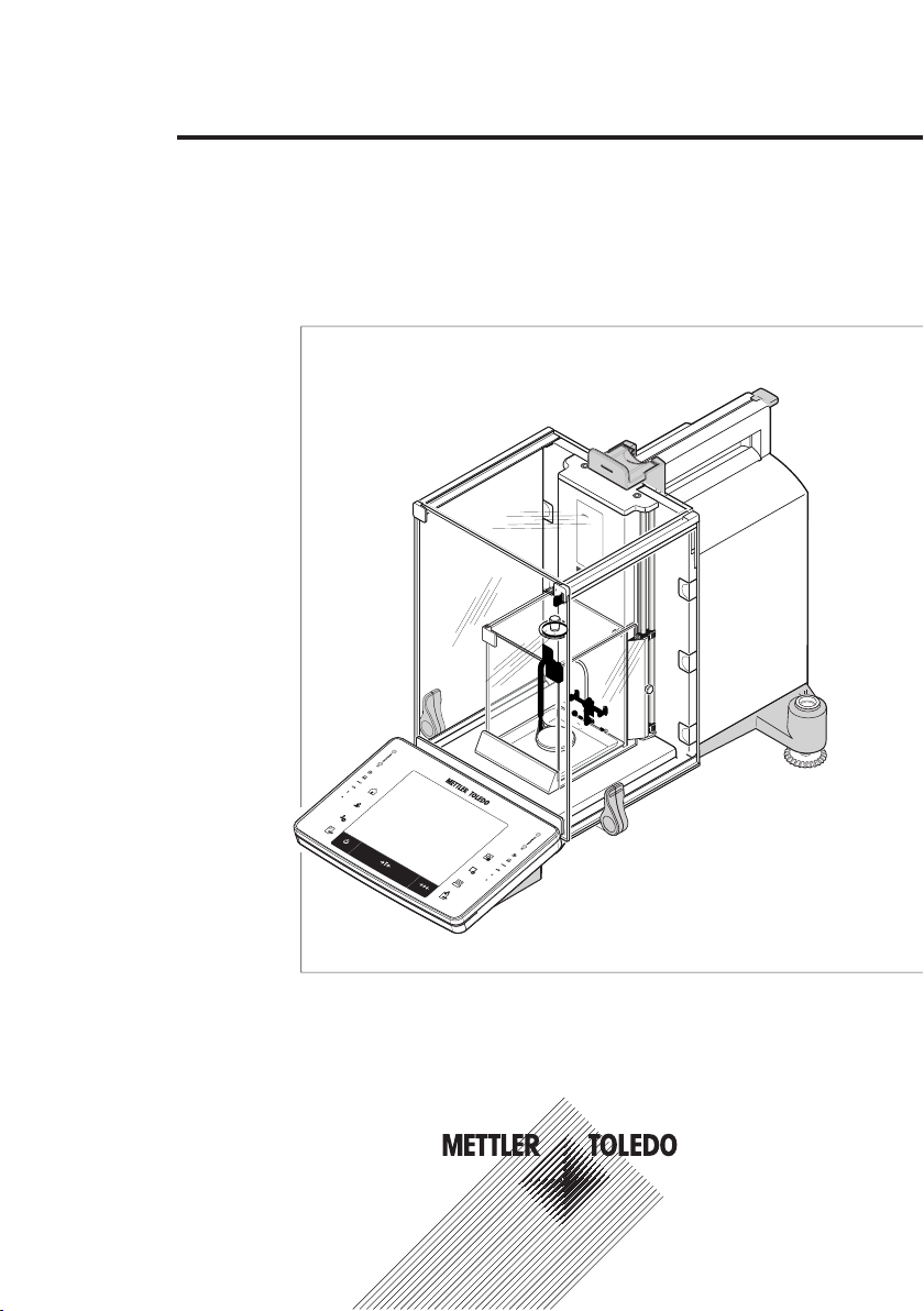
XP56
www.mt.com
XPE56C
ME
TTLER TOLEDO
XPE56/26/205CDR/505 models
Quick Guide
Comparator Balances
Page 2

Page 3

Table of Contents
1 Introduction 5
2 Safety Information 6
3 Design and Function 8
4 Installation and Putting into Operation 17
5 Maintenance 28
6 Technical Data 29
1.1 Conventions and symbols used in these operating instructions 5
2.1 Explanation of warnings and symbols 6
2.2 Product safety information 6
3.1 Overview 8
3.1.1 XPE56C/XPE26C balances 8
3.1.2 XPE205CDR/XPE505C balances 9
3.1.3 Terminal 10
3.2 User interface 12
3.2.1 Display 12
3.2.2 Input dialog boxes 13
3.2.3 Firmware 13
3.2.3.1 System settings 14
3.2.3.2 User profiles 14
3.2.3.3 User-specific settings 15
3.2.4 Security system 16
4.1 Unpacking 17
4.2 Location 18
4.3 Assembling the balance 19
4.3.1 Inner draft shield for XPE56C and XPE26C comparator balances 19
4.3.2 Outer draft shield 22
4.4 Connecting the balance 24
4.5 Setting up the balance 25
4.5.1 Weighing for the first time 25
4.5.1.1 Switching on the balance 25
4.5.1.2 Leveling the balance 25
4.5.1.3 Performing a simple weighing 26
4.5.2 Operating of the outer draft shield and the inner draft shield 26
5.1 Cleaning 28
5.2 Disposal 28
6.1 General data 29
6.2 Explanatory notes for the METTLER TOLEDO AC adapter 29
6.3 Model-specific data 30
Table of Contents 3Comparator Balances
Page 4

Page 5
1 Introduction
Thank you for choosing a METTLER TOLEDO balance.
The balances offers numerous weighing and adjustment options with exceptional operating convenience.
The different models have different characteristics regarding equipment and performance. Special notes in the text
indicate where this makes a difference to operation.
METTLER TOLEDO is a leading manufacturer of balances for laboratory and production use as well as analytical
measuring instruments. A globally present customer service network with highly trained personnel is always
available to assist with the selection of accessories or provide advice on the optimal use of the balance.
The balance conforms to current standards and directives. It supports requirements, work techniques and protocols
as specified by all international quality assurance systems, e.g. GLP (Good Laboratory Practice), GMP (Good
Manufacturing Practice). The balance has a CE Declaration of Conformity and METTLER TOLEDO, as the
manufacturer, is certified to ISO 9001 and ISO 14001. This provides the assurance that your capital investment is
protected in the long term by high product quality and a comprehensive service package (repairs, maintenance,
servicing, adjustment service).
Finding more information
u www.mt.com/comparators
More detailed information is in the Operating Instructions on the CD-ROM.
Software version
The operating instructions are based on the initially installed terminal firmware (software) version V 2.00.
1.1 Conventions and symbols used in these operating instructions
Key and button designations are shown in graphic or text form in square brackets (e.g. [
[Define].
These symbols indicate an instruction:
§ prerequisites
1 steps
2 ...
ð results
This symbol indicates press key briefly (less than 1.5 s).
] or
This symbol indicates press and hold key down (longer than 1.5 s).
Introduction 5Comparator Balances
Page 6
2 Safety Information
2.1 Explanation of warnings and symbols
Safety notes are indicated by signal words and warning symbols and contain warnings and information about
safety issues. Ignoring safety notes can lead to personal injury, damage to the instrument, malfunctions and
erroneous results.
Signal words
WARNING
CAUTION
Attention
Note
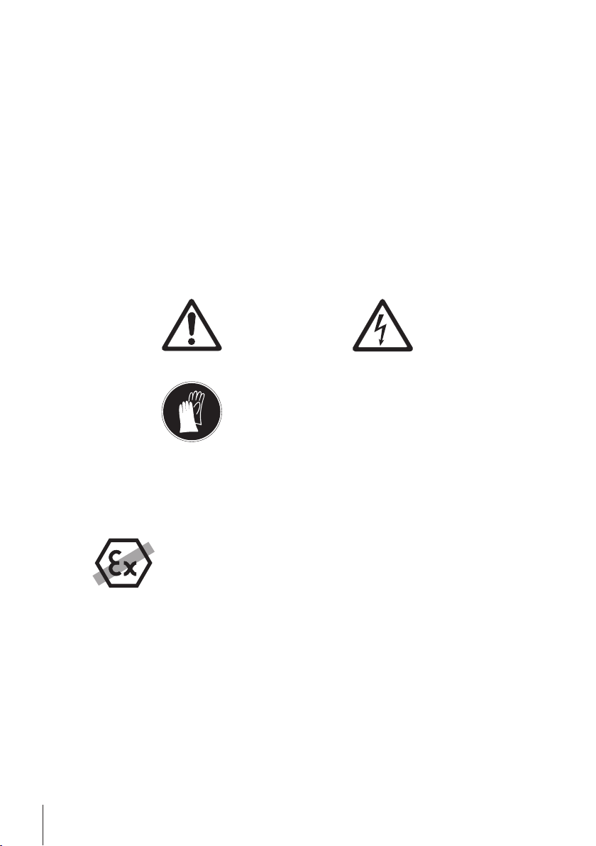
Warning symbols
Mandatory signs
for a hazardous situation with medium risk, possibly resulting in severe injuries
or death if not avoided.
for a hazardous situation with low risk, resulting in damage to the device or the
property or in loss of data or minor or medium injuries if not avoided.
(no symbol)
for important information about the product.
(no symbol)
for useful information about the product.
General hazard Electrical shock
Gloves must be worn
2.2 Product safety information
Intended use
Your balance is used for weighing. Use the balance exclusively for this purpose. Any other type of use and operation
beyond the limits of technical specifications without written consent from Mettler-Toledo AG, is considered as not
intended.
It is not permitted to use the instrument in explosive atmosphere of gases, steam, fog, dust and
flammable dust (hazardous environments).
General safety information
This balance complies with current industry standards and the recognized safety regulations; however, it can
constitute a hazard in use. Do not open the balance housing: The balance contains no user-serviceable parts. In the
event of problems, please contact a METTLER TOLEDO representative.
Always operate and use your instrument only in accordance with the instructions contained in this manual. The
instructions for setting up your new instrument must be strictly observed.
If the instrument is not used according to these Operating Instructions, protection of the instrument may be
impaired and METTLER TOLEDO assumes no liability.
Staff safety
These operating instructions must be read and understood before using the balance. These operating instructions
must be retained for future reference.
The balance must not be altered or modified in any way. Only use METTLER TOLEDO original spare parts and
accessories.
Safety Information6 Comparator Balances
Page 7
Safety notes
WARNING
Risk of electric shock
Use only the original universal AC adapter delivered with your balance, and check that the voltage
printed on it is the same as your local power supply voltage. Only plug the adapter into a socket
which is grounded.
CAUTION
Damage to the balance
a) Only use indoors in dry locations.
b) Do not use pointed objects to operate the touch screen!
The balance is of a very sturdy design, but is still a precision instrument. It must be handled
with care.
c) Do not open the balance:
The balance contains no user-serviceable parts. In the event of problems, please contact a
METTLER TOLEDO representative.
d) Only use METTLER TOLEDO original accessories and peripheral devices for the balance.
These are specifically designed for the balance.
Safety Information 7Comparator Balances
Page 8
3 Design and Function
1
5
6
7
2
3
8
9
12
13
11
10
15
7
14
17
18
19
16
www.mt.com
XP56
www.mt.com
XPE56C
XPE56C
ME
T
TLER
TOL
E
DO
4
2425
21 2022
23
3.1 Overview
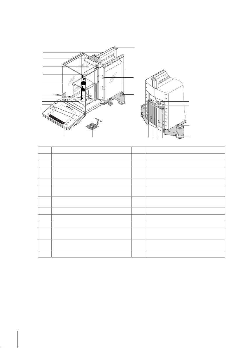
3.1.1 XPE56C/XPE26C balances
Terminal
1
Operating keys
3
Drip tray
5
Handle/Coupling element for the operation of
7
Display "Touch screen"
2
SmartSens sensors
4
Hanging weighing pan
6
Inner glass draft shield
8
the outer draft-shield doors
Outer glass draft shield
9
Type designation
11
StaticDetect light
10
Handle for operation of the outer draft-shield
12
top door
Guide for top door of draft shield and handle for
13
Removable clips for feeding cables or tubes
14
transport
Level indicator/Level sensor
15
Socket for AC adapter
17
Foot screw
19
RS232C serial interface
21
Slot for second interface (optional)
16
Fastening point for anti-theft device
18
Cooling element (based on model)
20
Aux 2 (connection for "ErgoSens", hand- or
22
foot-switch)
Aux 1 (connection for "ErgoSens", hand- or
23
SmartGrid weighing pan
24
foot-switch)
StatusLight
25
Design and Function8 Comparator Balances
Page 9
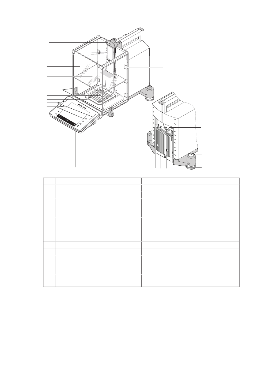
3.1.2 XPE205CDR/XPE505C balances
1
5
6
7
2
3
8
9
12
13
11
10
15
7
14
17
18
19
16
www.mt.
c
om
XP
E505C
F
F
METTLER TOLEDO
4
21 2022
23
24
Terminal
1
Operating keys
3
Drip tray
5
Handle/Coupling element for the operation of the
7
Display "Touch screen"
2
SmartSens sensors
4
SmartGrid weighing pan
6
Intermediate shelf
8
outer draft-shield doors
Glass draft shield
9
Type designation
11
Guide for top door of draft shield and handle for
13
15
17
19
21
23
transport
Level indicator / Level sensor
Socket for AC adapter
Foot screw
RS232C serial interface
Aux 1 (connection for "ErgoSens", hand- or footswitch)
StaticDetect light
10
Handle for operation of the outer draft-shield top
12
door
Removable clips for feeding cables or hoses
14
Slot for second interface (optional)
16
Fastening point for anti-theft device
18
Cooling element (based on model)
20
Aux 2 (connection for "ErgoSens", hand- or foot-
22
switch)
StatusLight
24
Design and Function 9Comparator Balances
Page 10
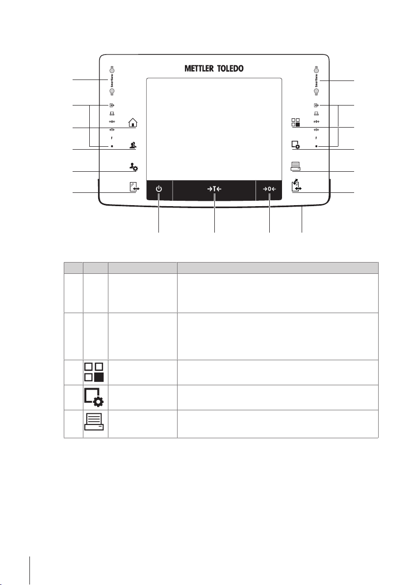
3.1.3 Terminal
7
8
10
9
1
2
14
13
12
11
1
2
3
4
5
6
Key assignments and terminal connection.
1: Front view
Designation Explanation
1
2
3
SmartSens Two hands-free sensors.
Status bar The green icons in the status bar indicate the functions assigned to the
Select application This key is used to select a required application.
Both of these hands-free sensors can be assigned a specific function
(e.g. zeroing, printing or display resolution adjustment).
See settings for SmartSens and ErgoSens in the respective applications.
SmartSens left or SmartSens right. The F symbol represents a function
key. SmartSens is deactivated when no green symbol is illuminated.
The yellow LED at the bottom of the status bar lights up briefly when a
key is selected or a menu function is initiated.
4
5
Configuration For displaying menus for the configuration of a current application. The
Print This key is used to transfer data via the interface, e.g. to a printer. Other
application can be adjusted to a specific task via numerous settings.
devices, e.g. a PC can also be connected. The data to be transferred
can be freely defined.
Design and Function10 Comparator Balances
Page 11
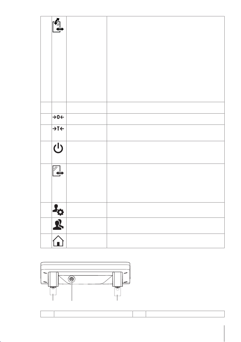
6
1 22
Open/Close For opening and closing the glass draft shield doors. For convenient
right and left-handed operation, one of these keys is provided on both
sides of the terminal.
Note
The key can have different functions if a powder module or autosampler
is installed.
• If powder module and front door are defined as mounted, the key
operates the front door.
• If powder module is defined as mounted and front door is defined as
unmounted, the key operates the side doors.
• If autosampler and front door are defined as mounted, the key
operates the front door.
• If autosampler is defined as mounted and front door is defined as
unmounted, the key turns the autosampler clockwise by 1magazine
= 5positions.
Refer to your Autosampler Operating Instructions for further information.
7
StatusLight Indicates the current balance status. The status light shows that the
balance is ready to use.
8
Zeroing This key is used for setting a new zero point manually (only required if
the balance is used for normal weighings).
9
Tare This key is used to tare the balance manually (only necessary for
normal weighings). When the balance has been tared, the Net symbol
is displayed to indicate that all displayed weights are net.
10
On/Off For switching the balance on and off (standby mode).
Note
It is recommended not to disconnect the balance from the power supply
unless it is not going to be used for an extended period.
11
Open/Close For opening and closing the glass draft shield doors. For convenient
right and left-handed operation, one of these keys is provided on both
sides of the terminal.
Note
The key can have different functions if an autosampler is installed.
• If the autosampler is defined as mounted, the key turns the
autosampler on counterclockwise by 1 magazine = 5 positions.
12
Settings for user
profiles
For defining basic settings for each user profile. These settings apply to
all user applications.
13
User profile This key is used to display a specific user profile. Different settings can
be saved in a user profile. This allows the balance to be adjusted to a
specific user or weighing task.
14
Home
This key is used to return to the user profile Home from any menu level
in any application.
System connection (terminal cable)
1
Height adjustable feet
2
Design and Function 11Comparator Balances
Page 12

3.2 User interface
6
7
8
5
4
1 2 3
9
3.2.1 Display
The illuminated, color display of the terminal is a touch screen, i.e. a touch-sensitive screen. It can be used for
displaying data, entering settings and selecting functions by tapping the screen.
Note
Depending on country-specific requirements, non-calibrated decimal places are highlighted on approved balances.
CAUTION
Do not touch the touch screen with pointed or sharp objects!
This may damage the touch screen.
Designation Explanation
Application name Select application.
1
The application menu can be selected by tapping this zone. This menu can also be
displayed by pressing [
Current user profile Displays the current user profile.
Date The date can be changed by tapping this zone.
2
Time The time can be changed by tapping this zone.
3
Status icons These status icons indicate special balance statuses (e.g. service due, adjustment
4
Weight value Tapping the weight displays a window showing the result in a large format. This is
5
Weighing unit The required weighing unit can be changed by tapping the weighing unit, e.g. from
6
SmartTrac SmartTrac is a graphic weighing-in aid, which shows at a glance an already used
7
Function keys
8
Information fields
9
required, battery replacement, out of level).
If you tap the icon, the function is explained.
useful for reading a weight from a certain distance.
mg to g.
and still available weighing range.
This area is reserved for Function Keys enabling direct access to frequently required
functions and application settings. If more than 5 function keys are activated, these
can be selected with the arrow keys.
This area is used for displaying additional information (information fields) relating
to an active application. Tapping the information field enables Information fields
and Function Keys to be displayed directly via menu selection. The leveling
assistant can also be started.
].
Design and Function12 Comparator Balances
Page 13

Large display
1
2
3
By pressing the function key [Display], the weighing result can be displayed larger and still allow the use of the
terminal function keys.
Screen saver
If the balance is not used for 15 minutes, the display is automatically dimmed and the pixels are inverted about
every 15 seconds. When the balance is used again (e.g. load weight, press key), the display returns to a normal
state.
3.2.2 Input dialog boxes
The keyboard dialog box is used to enter characters such as letters, numbers and special characters.
Designation Explanation
Data field Displays (entered) alphanumeric and numeric characters.
1
Keyboard Data input area
2
Selection Select various keyboard layouts.
3
1 Enter the designation.
2 Confirm with [OK].
Function
Delete last character
Tap once to place the cursor at the end of the data field.
3.2.3 Firmware
The firmware controls all balance functions. It enables the balance to be adjusted to a specific working environment.
The firmware is divided as follows:
• System settings
• User profiles
• User-specific settings
• Applications
Design and Function 13Comparator Balances
Page 14

• Application-specific settings
1
2
3
1
2
4
3
Note
A displayed menu can be left at any time by repressing the same menu key.
3.2.3.1 System settings
System settings (e.g. settings for peripheral devices) are independent of the user profiles and applications and apply
to the entire weighing system. System settings can be displayed by pressing [
button.
Navigation: [
or
Navigation: [
1
2
3
1 Settings can be changed by tapping the respective button.
2 To leave the settings, tap [Exit].
3.2.3.2 User profiles
User profiles are used to adjust the balance to suit specific applications and personal work techniques or specific
weighing tasks. A user profile is a collection of user defined settings that can be selected at the press of a button.
The last active user profile is automatically loaded when the balance is switched on.
Navigation: [
] > System
] > System
Designation Explanation
Title bar The title bar displays elements for user orientation and information.
Contents area The contents area is the main work area for menus and applications. The contents
depend on the specific application or initiated action.
Action bar The action bar contains action buttons for performing specific actions required in
the active dialog box and are available (e.g. [Exit], [STD], [C], [OK]).
]
] or [ ] and then the [System]
Designation Explanation
Title bar The title bar displays elements for user orientation and information.
1
Design and Function14 Comparator Balances
Page 15

Contents area The contents area is the main work area for menus and applications. The contents
1
2
3
1
2
3
2
Home
3
User profiles Settings in further user profiles can be changed as required. All settings made in an
4
- A user profile can be changed by tapping the respective button.
3.2.3.3 User-specific settings
These settings can be used to adjust the balance to suit the tasks and work techniques of individual users. The
settings can be defined separately for each user profile and for the Home profile. When a user profile is selected, the
corresponding user-specific settings are automatically loaded.
Navigation: [
Applications
Applications are firmware modules for performing specific weighing tasks. The balance is delivered with various
applications pre-installed. After switching on the balance, the last active user profile and last used application are
loaded. The applications are available under the [
provided in the respective sections.
Navigation: [
]
]
depend on the specific application or initiated action.
The Home profile is a starting point that can be returned to at any time by pressing
] key. It contains factory settings for all users. These settings can be
the [
changed as required. It is recommended not to change the Home profile factory
settings, but make adjustments in further user profiles.
active user profile are saved under this profile. This includes both application and
user-specific settings. The system settings are not changed.
] key. Instructions for working with standard applications are
Application-specific settings
These settings can be used to adjust the applications to suit individual user requirements. The available setting
options depend on the selected application. Pressing [
active application. Information on the individual setting options is provided in the section relating to the respective
application. Settings can be defined separately for each user profile and for the Home profile. When a user profile is
selected, the corresponding application-specific settings are automatically loaded.
] opens the multipage menu with settings for a currently
Design and Function 15Comparator Balances
Page 16

Navigation: [ ]
5
4
1
2
3
Designation Explanation
Title bar The title bar displays elements for user orientation and information.
1
Contents area The contents area is the main work area for menus and applications. The contents
2
Action bar The action bar contains action buttons for performing specific actions required in
3
Button
4
Arrow The arrow buttons are used to page forward or back.
5
1 Settings can be changed by tapping the respective button.
2 Confirm with [OK].
3 To leave the settings, select [Exit].
4 To change the system settings, tap [System].
depend on the specific application or initiated action.
the active dialog box and are available (e.g. [Exit], [STD], [C], [OK]).
Edit/Select settings (e.g. [Define], [On], [Off]). The contents depend on the
application.
3.2.4 Security system
The balance has a comprehensive security system with which individual access rights can be defined at
administrator and user level. Settings that may be changed can be defined for each individual user profile. Access to
protected menu areas requires the entry of identification (ID) and a password. On delivery of the balance, only the
[Administrator] settings in the system settings are protected.
When an ID and password protected menu area is selected, an alphanumeric keyboard is initially displayed for
entry of the ID.
CAUTION
Remember IDs and passwords!
Protected menu areas cannot be accessed without ID or password.
a) Note IDs and passwords and keep them in a safe place.
1 Enter your ID.
- Case sensitive, tap the [a...z] and [A...Z] button to switch between upper and lower case.
- To enter numbers, tap the [0...9] button.
- Incorrect entries can be deleted character by character with the arrow key
Design and Function16 Comparator Balances
Note
Entry can be interrupted at any time by tapping [C].
2 After entering the full ID, tap [OK].
ð A further dialog box is displayed for entering the password.
3 Enter the password (for security reasons, this is displayed with asterisks instead of plain text) and confirm with
[OK].
ð If the ID and password are correct, the selected menu area is displayed or the required action initiated. If these
are incorrect, an error message is displayed with a request to enter them again.
.
Page 17

4 Installation and Putting into Operation
1
2
3
4
1
2
4.1 Unpacking
Open the balance packaging. Check the balance for transport damage. Immediately inform a METTLER TOLEDO
representative in the event of complaints or missing accessories.
Note
Retain all parts of the packaging. This packaging offers the best possible protection for transporting the balance.
1 Open the outer packaging box.
2 Remove it from the packaging the Unpacking and packing
instructions.
3 Lift the cardboard box (1) out of the packaging.
4 Remove the operating instructions (2).
5 Remove the set (3) with AC adapter, power supply cable,
tweezers, and the set containing ErgoClip basket micro and
SmartGrid cover micro.
6 Remove the set with outer draft shield doors (4) and terminal
support.
- Use the lifting strap to lift the balance out of the packaging box.
1 Remove the lifting strap (1).
2 Remove the top packaging (2).
Installation and Putting into Operation 17Comparator Balances
Page 18

3 Remove the set (3) with inner draft shield etc.
3
4
5
6
4
5
4 Carefully remove the terminal (4) from the bottom packaging
(5).
5 Remove the protective cover.
Note
Since the terminal is connected to the balance with a cable, only
withdraw the balance slightly from the packaging in order to remove
the protective cover.
6 Place the terminal (4) at the front of the balance.
7 Hold the balance (6) by the guide or handle. Hold the terminal
firmly with the other hand. Pull out both components together
from the bottom packaging (5).
8 Place the balance with the terminal at the site of use.
9 Remove the cover from the balance.
4.2 Location
An optimal location will ensure accurate and reliable operation of the balance. The surface must be able to safely
take the weight of the balance when fully loaded. The following local conditions must be observed:
Note
Installation and Putting into Operation18 Comparator Balances
If the balance is not horizontal at the outset, it must be leveled during commissioning.
Page 19

• The balance must only be used indoors and up to a maximum
XP56
1
2
1
altitude of 4,000 m above sea level.
• Before switching on the balance, wait until all parts are at room
temperature (+5 to 40°C).
The humidity must be between 10% and 80% non-condensing.
• The power plug must be accessible at all times.
• Firm, horizontal and vibration-free location.
• Avoid direct sunlight.
• No excessive temperature fluctuations.
• No strong drafts.
Further information can by found in Weighing the Right Way.
4.3 Assembling the balance
4.3.1 Inner draft shield for XPE56C and XPE26C comparator balances
1 Insert the front glass (1) of the inner draft shield.
2 Ensure the glass is centered and pushed in as far as the stop.
3 Insert the drip tray (1) from the side under the upper 2 pins. The
notches must be positioned by the springs.
4 Insert the SmartGrid (2) from above.
5 Check that the SmartGrid is correctly hooked in on both sides.
Hanging weighing pan
CAUTION
Damage of device
When installing the hanging weighing pan, it is advisable to wear gloves.
Installation and Putting into Operation 19Comparator Balances
Page 20

1 Insert the drip tray (1).
3
2
1
2
1
XPE56C
www.mt.com
XP56
2
A
1
2 Insert the support (2).
3 Check that the guide is correctly installed on both sides.
4 Place the hanging weighing pan (3) on the swivel bearing by
the support (2).
Attention
5 After you have installed the hanging weighing pan (balance in
operation) you must switch the balance off and then switch it on
again [
] key.
SmartGrid
1 Insert the drip tray (1) from the side under the upper 2 pins. The
notches must be positioned by the springs.
2 Insert the SmartGrid (2) from above.
3 Check that the SmartGrid is correctly hooked in on both sides.
1 Insert the side window (1) of the inner draft shield.
2 At an angle of approximately 45 degrees to the final position,
place the 2 black clips on the back guide shaft.
3 Push the window up until you can swivel it in over the front
glass.
Installation and Putting into Operation20 Comparator Balances
Page 21

4 Insert the window (1) of the inner draft shield into the guide of
XPE56C
www.mt.com
XP56
1
2
1
2
the front glass and lower it to the floor.
5 The window must run easily.
6 Press the coupling pins (2) toward the inside.
7 Now insert the window on the other side of the inner draft shield.
The procedure is the same.
1 Put the top glass (1) on.
2 Insert the sealing cover (2).
Note
The sealing cover closes the opening in the top glass through which
you can pipette into a high container.
Attention
Do not use the sealing cover to lift the top glass of the draft shield!
Installation and Putting into Operation 21Comparator Balances
Page 22

4.3.2 Outer draft shield
1
2
1 Insert the top draft shield door (1) at an angle (slightly below 30
degrees) into the rear guide.
2 Carefully fold the draft shield door (2) downwards, see figure.
Installation and Putting into Operation22 Comparator Balances
Page 23

§ The handles (A) must be turned toward the outside to allow
www.mt.com
XP56
A
A
4
2
3
1
1
2
installation of the side draft shield doors!
1 Insert the side doors of the draft shield according to the following
instructions, see figure below.
2 Insert the side door at an angle of approx. 30° into the 2
openings, see figure.
3 Check that the side door is correctly inserted as shown!
4 Swivel the side door up against the balance until it engages with
a click.
5 The side door must run easily, otherwise it is not correctly
inserted.
6 Insert the second side door of the draft shield.
ð The procedure is identical.
7 Push the side doors completely to the back.
1 Insert the front glass (2) of the draft shield.
2 In the bottom part of the balance at the front, move at an angle
from the top toward the bottom until the two hooks of the front
glass of the draft shield lie on the rollers (1).
3 Swivel the front glass of the draft shield up until it engages.
Installation and Putting into Operation 23Comparator Balances
Page 24

1 Insert the terminal support.
2 Place the cable in the guide of the terminal support.
3 Insert the terminal support into the opening in the front draft
shield glass.
ð The terminal support must engage with a click.
1 Mount the terminal.
2 Place the terminal in the center of the support.
3 Push the terminal against the balance until it folds down easily
at the front of the terminal support.
4 Insert the cable into the balance.
Attention
The balance and terminal are not connected by the terminal support! Always hold the balance and terminal firmly
during transport.
Note
The Terminal cable is of sufficient length to allow repositioning of the terminal in the area around the balance.
4.4 Connecting the balance
WARNING
Risk of electric shock
a) To connect the balance, only use the supplied three-core power cable with equipment
grounding conductor.
b) Only connect the balance to a three-pin power socket with earthing contact.
c) Only standardized extension cable with equipment grounding conductor must be used for
operation of the balance.
d) Intentional disconnection of the equipment grounding conductor is forbidden.
The balance is supplied with an AC adapter and country-specific power cable. The AC adapter is suitable for use
with the following voltage range:
100 – 240 VAC, 50/60Hz.
Attention
• Check whether your local power supply falls within this range. If this is not the case, under no circumstances
connect the AC adapter to the power supply, but contact a METTLER TOLEDO representative.
• The power plug must be accessible at all times.
• Prior to use, check the power cable for damage.
• Route the cable in such a way that it cannot be damaged or cause a hindrance when working.
• Ensure that no liquid comes into contact with the AC adapter.
Installation and Putting into Operation24 Comparator Balances
Page 25

§ Balance and terminal are at the final location.
2
1
1 Connect the AC adapter (1) to the connection socket (2) at the
rear of the balance.
2 Connect the AC adapter (1) to the power supply.
ð The balance performs a self-test after connection to the power
supply and is then ready to use.
4.5 Setting up the balance
4.5.1 Weighing for the first time
After commissioning the new balance, the first weighing can be carried out. This will also familiarize you with the
operation of the balance.
If the balance is not exactly level, a warning text is generated after switching on the balance with the request to level
the balance.
4.5.1.1 Switching on the balance
§ Balance is connected to the power supply.
§ Terminal and balance are interconnected.
- To switch on, press [
ð Display appears.
ð Balance is ready to use.
4.5.1.2 Leveling the balance
The balance has a built-in level sensor which permanently monitors correct horizontal alignment.
If the level sensor detects incorrect leveling, the status light at the
terminal shows red. A warning text is displayed and an audible
warning generated. A status icon also appears in the top right
corner of the display.
].
Installation and Putting into Operation 25Comparator Balances
Page 26

1 To start the leveling assistant, tap [LevelGuide] in the warning
message.
ð Window with level indicator is displayed in real-time.
2 Observe the level indicator on the screen.
ð The air bubble in the level indicator shows red with incorrect
alignment.
ð The leveling assistant indicates with red arrows the direction
in which the two foot screws at the rear of the balance must
be turned.
3 Turn the foot screw until the air bubble is located in the inner
circle of the level indicator.
ð The air bubble in the level indicator shows green with correct
alignment.
ð The status light at the terminal shows green.
4 Tap [OK].
ð A message recommending adjustment of the balance is
displayed.
5 Tap [Adjust.int] to adjust the balance.
4.5.1.3 Performing a simple weighing
To perform a simple weighing, only the keys in the lower part of the terminal are required. The balance has separate
keys for zeroing [
Zeroing
- Press [
ð Zeroing
After zeroing, all weights also the tare weight apply to this new zero point and the following apply: tare weight = 0,
net weight = gross weight = 0.
Taring
Note
A negative weight is not permitted. An error message is generated. When the stability detector icon extinguishes
(small ring left of the weight display), the indication is stable. The weight is displayed.
§ If a weighing container is used, the balance must first be set to
zero.
1 Place the container on the balance.
2 Press [
ð The balance is tared.
ð The weight of the container is set as the new tare weight and the
previous tare (if available) is overwritten.
ð The Net display signals that all indicated weights are net
weights.
] and taring [ ].
].
].
Congratulations!
The first weighing is now complete. The following sections contain further information about the extensive functions
and applications of this balance.
4.5.2 Operating of the outer draft shield and the inner draft shield
Outer draft shield
The outer draft shield of the balance can be adjusted to the ambient conditions, weighing method and material to be
weighed.
The outer glass draft shield doors can be opened and closed by pressing [
manually .
Installation and Putting into Operation26 Comparator Balances
], with the "SmartSens" sensors or
Page 27

Try different combinations by moving the 3 handles upwards/inwards and downwards/outwards. We recommend
1
aligning the glass draft shield so that only those parts are opened that are required for loading. The balance then
operates faster due to less disturbing air flows than with a fully open glass draft shield.
Note
It is recommended to make connections when the draft shield is closed.
Motorized operation
The automatic door function opens and closes the doors of the glass draft shield automatically when required.
Example
• Doors open automatically for loading the tare weight when [
] is pressed.
• When a request is made to load the adjustment weight while adjusting the balance, the doors open
automatically. The doors close automatically when the weight is loaded.
• The glass draft shield closes automatically for all weighings to achieve a stable weight indication.
• For different operations (e.g. piece counting), the doors open and close automatically as required by the
application.
§ Handles are locked.
1 Move the handles for the side
doors inwards.
2 Move the handle for the top
door into the horizontal
position.
ð The door is automatically
opened when required.
Manual door operation
The doors must be opened or closed manually. With the [
] keys, via SmartSens or manually.
§ Handles are unlocked.
1 Move the handles for the side doors outwards.
2 Move the handle for the top door into the vertical position.
3 Press [
].
or
Move the hand over the SmartSens sensor.
ð The door is opened.
Inner draft shield
- For motorized operation of the inner draft shield the coupling
bolts (1) must be pressed inward.
ð The two side doors can be controlled separately.
You can also open the side doors of the inner draft shield only
partway, with a choice of 25%, 50% or 75%.
Installation and Putting into Operation 27Comparator Balances
Page 28

5 Maintenance
5.1 Cleaning
Periodically clean the weighing pan, the drip tray, the housing, and the terminal of your balance using the brush
supplied with it. The maintenance interval depends on your standard operating procedure (SOP).
Please observe the following notes:
WARNING
Risk of electric shock
a) Disconnect the balance from the power supply prior to cleaning and maintenance.
b) Only use METTLER TOLEDO power cable, if these need to be replaced.
c) Ensure that no liquid comes into contact with the balance, terminal or AC adapter.
d) Do not open the balance, terminal or AC adapter.
These contain no user-serviceable parts.
CAUTION
Damage to balance
Under no circumstances use cleaning agents containing solvents or abrasive agents, as this can
damage the terminal overlay.
Cleaning
Your balance is made from high quality, resistant materials and can therefore be cleaned with a commercially
available, mild cleaning agent.
Note
All removable non-coated parts of the outer draft shield are dishwasher safe to 80 degrees. The sealing cover of the
inner draft shield is not dishwasher safe.
1 To clean the weighing chamber thoroughly, move the draft shield glass panels (including intermediate shelf)
away from the balance and remove them from their fastenings.
2 Carefully lift the front of the weighing pan and lift it out of the guide.
3 Remove the drip tray from the balance.
4 Ensure that these parts are correctly positioned when refitted.
Note
Contact a METTLER TOLEDO representative to find about the service options available – regular maintenance by an
authorized service engineer will ensure consistent weighing accuracy over the long term and extend the service life
of the balance.
5.2 Disposal
In conformance with the European Directive 2002/96/EC on Waste Electrical and Electronic
Equipment (WEEE) this device may not be disposed of in domestic waste. This also applies to
countries outside the EU, per their specific requirements.
Please dispose of this product in accordance with local regulations at the collecting point
specified for electrical and electronic equipment. If you have any questions, please contact the
responsible authority or the distributor from which you purchased this device. Should this device
be passed on to other parties (for private or professional use), the content of this regulation must
also be related.
Thank you for your contribution to environmental protection.
Maintenance28 Comparator Balances
Page 29

6 Technical Data
6.1 General data
CAUTION
Only use an approved AC adapter with a current-limited SELV output.
Ensure correct polarity
Power supply
AC adapter: Primary: 100–240VAC, -15%/+10%, 50/60Hz
Cable for AC adapter: 3-core, with country-specific plug
Balance power supply: 12VDC ±3%, 2.25A, maximum ripple: 80mVpp
Protection and standards
Overvoltage category: II
Degree of pollution: 2
Protection: Protected against dust and water
Standards for safety and EMC: See Declaration of Conformity
Range of application: For use only in closed interior rooms
Environmental conditions
Height above mean sea level: Up to 4000m
Ambient temperature: 5–40°C
Relative air humidity: Max. 80% up to 31°C, linearly decreasing to 50% at 40°C,
Warm-up time:
Materials
Housing: Die-cast aluminum, plastic, chrome steel and glass
Terminal: Die-cast zinc, chromed and plastics
Hanging weighing pan and SmartGrid: Chrome-Nickel-Molybdenum steel X2CrNiMo17
Secondary: 12 V DC ±3%, 2.5 A (with electronic overload
protection)
noncondensing
At least 12 hours after connecting the balance to the power supply.
The balance should not be switched into standby mode.
6.2 Explanatory notes for the METTLER TOLEDO AC adapter
The certified external power supply which conforms to the requirements for Class II double insulated equipment is
not provided with a protective earth connection but with a functional earth connection for EMC purposes. This earth
connection IS NOT a safety feature. Further information about conformance of our products can be found in the
brochure "Declaration of Conformity" which is coming with each product.
In case of testing with regard to the European Directive 2001/95/EC the power supply and the balance have to be
handled as Class II double insulated equipment.
Consequently an earth bonding test is not required. Similarly it is not necessary to carry out an earth bonding test
between the supply earth conductor and any exposed metalwork on the balance.
Technical Data 29Comparator Balances
Page 30

10 kΩ coupling resistor for
electrostatic discharge
Input 100…240 V
AC Output 12 VDC
Double Insulation
Plastic Housing
P
N
E
AC
DC
Because the balance are sensitive to static charges a leakage resistor, typically 10 kΩ, is connected between the
earth connector and the power supply output terminals. The arrangement is shown in the equivalent circuit diagram.
This resistor is not part of the electrical safety arrangement and does not require testing at regular intervals.
2: Equivalent circuit diagram
6.3 Model-specific data
More detailed information is in the Operating Instructions on the CD-ROM.
XPE26C XPE56C
Limit values
Maximum capacity 22 g 52 g
Readability 0.001 mg 0.001 mg
Tare range (from…to) 0 … 22 g 0 … 52 g
Maximum capacity in fine range – –
Readability in fine range – –
Repeatability (at nominal load) sd 0.002 mg (20 g) 0.0045 mg (50 g)
Repeatability (at low load) sd 0.0007 mg (1 g) 0.003 mg (2 g)
Repeatability in fine range (at nominal load) – –
Repeatability in fine range (at low load) – –
Repeatability at nominal load (ABA)
Repeatability at low load (ABA)
Linearity deviation 0.006 mg 0.02 mg
Eccentricity deviation (test load)
Sensitivity offset (test weight) 0.08 mg (20 g) 0.125 mg (50 g)
Sensitivity temperature drift
Sensitivity stability
Typical values
Repeatability (at nominal load) sd 0.0015mg (20 g) 0.003 mg (50 g)
Repeatability at nominal load (ABA)
Linearity deviation 0.0016 mg 0.1605 mg
Eccentricity deviation (test load)
Sensitivity offset (test weight) 0.02 mg (20 g) 0.03 mg (50 g)
Minimum weight (according to USP) 1.2 mg 1.4 mg
Minimum weight (U=1%, k=2) 0.12 mg 0.14 mg
Interface update rate 23 1/s 23 1/s
Weight of balance 11.5 kg 11.5 kg
3)
Technical Data30 Comparator Balances
4)
4)
1)
2)
4)
1)
0.0015 mg (20 g) 0.003 mg (50 g)
0.0007 mg (1 g) 0.0007 mg (2 g)
0 mg (10 g) 0 mg (20 g)
0.0001%/°C 0.0001%/°C
0.0001%/a·Rnt 0.0001%/a·Rnt
sd 0.0012 mg (20 g) 0.0026 mg (50 g)
0 mg (10 g) 0 mg (20 g)
Page 31

Number of built-in reference weights 2 2
Dimensions
Balance dimensions (W×D×H) 263 × 493 × 322 mm 263 × 493 × 322 mm
SmartGrid dimensions 40x40 mm (WxD) 40x40 mm (WxD)
Hanging weighing pan dimensions ∅ 35 mm ∅ 35 mm
Weights for routine testing
OIML CarePac
Weights
ASTM CarePac
Weights
Calibration weights 20g E1 CM #00159131
sd = Standard deviation
1)
According to OIML R76
3)
After putting into operation for the first time, with the selfadjustment function activated (ProFACT or FACT)
4)
Value out of 5 ABA measurements according to OIML R111
#11123006
20 g F1, 1 g E2
#11123106
20 g 1, 1 g 1
20g ASTM 0 CM
2)
In the temperature range 10…30°C
#11123003
50 g F2, 2 g E2
#11123103
50 g 1, 2 g 1
50g E1 CM #00159141
50g ASTM 0 CM
More detailed information is in the Operating Instructions on the CD-ROM.
XPE205CDR XPE505C
Limit values
Maximum capacity 220 g 520 g
Readability 0.1 mg 0.01 mg
Tare range (from…to) 0 … 220 g 0 … 520 g
Maximum capacity in fine range 81 g –
Readability in fine range 0.01 mg –
Repeatability (at nominal load) sd 0.06 mg (200 g) 0.06 mg (500 g)
Repeatability (at low load) sd 0.05 mg (10 g) 0.03 mg (20 g)
Repeatability in fine range (at nominal load) sd 0.04 mg (200 g) –
Repeatability in fine range (at low load) 0.015 mg (10 g) –
Repeatability at nominal load (ABA)
Repeatability at low load (ABA)
Linearity deviation 0.15 mg 0.2 mg
Eccentricity deviation (test load)
Sensitivity offset (test weight) 0.5 mg (200 g) 1.25 mg (500 g)
Sensitivity temperature drift
Sensitivity stability
3)
Typical values
Repeatability (at nominal load) sd 0.0505 mg (200 g) 0.04 mg (500 g)
Repeatability at nominal load (ABA)
Linearity deviation 0.051 mg 0.14 mg
Eccentricity deviation (test load)
Sensitivity offset (test weight) 0.2 mg (200 g) 0.25 mg (500 g)
Minimum weight (according to USP) 80 mg 40 mg
Minimum weight (U=1%, k=2) 8 mg 4 mg
Interface update rate 23 1/s 23 1/s
Weight of balance 10 kg 10 kg
Number of built-in reference weights 2 2
Dimensions
Balance dimensions (W×D×H) 263 × 493 × 322 mm 263 × 493 × 322 mm
SmartGrid dimensions 78x73 mm (WxD) 78x73 mm (WxD)
Weights for routine testing
4)
4)
1)
2)
0.05 mg (200 g) 0.035 mg (500 g)
0.015 mg (10 g) 0.01 mg (20 g)
0.25 mg (100 g) 0.2 mg (200 g)
0.0001%/°C 0.0001%/°C
0.0001%/a·Rnt 0.0001%/a·Rnt
4)
1)
sd 0.0175mg (200 g) 0.031 mg (500 g)
0.06 mg (100 g) 0.1 mg (200 g)
Technical Data 31Comparator Balances
Page 32

OIML CarePac
Weights
ASTM CarePac
Weights
#11123001
200 g F2, 10 g F1
#11123101
200 g 1, 10 g 1
Calibration weights 200g E1 CM #00159161
200g ASTM 0 CM
sd = Standard deviation
1)
According to OIML R76
3)
After putting into operation for the first time, with the selfadjustment function activated (ProFACT or FACT)
4)
Value out of 5 ABA measurements according to OIML R111
2)
In the temperature range 10…30°C
#11123007
500 g F2, 20 g F1,
#11123107
500 g 1, 20 g 1,
500g E1 CM #00159171
500g ASTM 0 CM
Technical Data32 Comparator Balances
Page 33

Page 34

Page 35

Page 36

Mettler-Toledo AG, Laboratory Weighing
CH-8606 Greifensee, Switzerland
Tel. +41 (0)44 944 22 11
Fax +41 (0)44 944 30 60
www.mt.com
Subject to technical changes.
© Mettler-Toledo AG 08/2015
30134557B en
www.mt.com/comparators
Further information
*30134557*
 Loading...