

Page 1

User Manual
XMV Tamper Evident
Document Version A
Page 2

Intentionally left blank
2 / 38 XMV-TE - User Manual - Document Version A
Page 3

Table of Contents
1 Introduction 5
1.1 Intended Audience........................................................................................................ 5
1.2 Intended Use and Foreseeable Misuse ............................................................................ 5
1.3 Original Language ....................................................................................................... 5
1.4 Contacting METTLER TOLEDO Service............................................................................. 5
1.5 Additional Documents .................................................................................................. 6
1.6 Warranty .................................................................................................................... 6
2 Important Safety Information 7
2.1 Safety Labels and Notice Labels .................................................................................... 7
2.2 General Protective Procedures ....................................................................................... 9
2.3 Safety Information for Various Activities........................................................................... 10
2.4 Special Hazards .......................................................................................................... 11
2.1.1 Hazard Notifications ...................................................................................... 7
2.1.1.1 Definitions of Signal Words ...................................................................... 7
2.1.1.2 Meaning of Hazard Alert Symbols.............................................................. 7
2.1.2 Mandatory Procedures................................................................................... 8
2.1.3 Prohibited Procedures.................................................................................... 9
2.1.4 Notice.......................................................................................................... 9
2.1.5 Note ............................................................................................................ 9
2.3.1 Transporting and Moving the Equipment .......................................................... 10
2.3.2 Installing...................................................................................................... 10
2.3.3 Operating the Equipment and Monitoring the Inspection Process......................... 10
2.3.4 Testing and Verifying the Equipment ................................................................ 11
2.3.5 Maintaining, Cleaning and Sanitizing the Equipment ......................................... 11
2.4.1 Electricity ..................................................................................................... 11
2.4.2 Pneumatics .................................................................................................. 11
2.4.3 Moving Parts ................................................................................................ 11
2.4.4 Rejectors...................................................................................................... 12
2.4.5 Noise........................................................................................................... 12
2.4.6 Strobe Lights ................................................................................................ 12
2.4.7 Lights and Laser Sensors ............................................................................... 12
3 Equipment Overview 13
3.1 Equipment Function ..................................................................................................... 13
3.1.1 Workflow XMV Tamper Evident ....................................................................... 13
3.1.2 Limitation of Workflow ................................................................................... 14
3.1.3 Possible label positions Tamper Evident .......................................................... 14
3.2 Equipment Description.................................................................................................. 16
3.3 Equipment Options....................................................................................................... 19
3.3.1 Overview of Optional Mechanical Equipment .................................................... 19
3.3.2 Full Housing................................................................................................. 19
3.3.3 Rejection System Options............................................................................... 19
3.3.4 Conveyor Options.......................................................................................... 19
4 Transporting, Moving, and Storage 20
4.1 Transporting the Equipment........................................................................................... 20
4.2 Storing the Equipment .................................................................................................. 20
4.3 Unpacking the Equipment ............................................................................................. 21
4.4 Moving the Equipment and Setting it in Place .................................................................. 21
4.5 Preparing for Transporting (After First Installation)............................................................ 22
5 Installation 23
6 Operation 24
6.1 Using the Emergency Stop Button .................................................................................. 24
6.2 Adjusting the Input Conveyor......................................................................................... 24
6.3 Adjusting the Rejection System for the Product's Weight ................................................... 24
6.4 Starting Production....................................................................................................... 24
6.5 Ending Production ....................................................................................................... 25
XMV-TE - User Manual - Document Version A 3 / 38
Page 4

6.6 Switching down the Equipment...................................................................................... 25
7 Cleaning 26
7.1 Using Detergents.......................................................................................................... 26
7.2 Cleaning Procedure...................................................................................................... 26
7.3 Visual Inspection and Cleaning of the System.................................................................. 27
7.4 Cleaning the Cover....................................................................................................... 27
7.5 Restarting the System after Sanitization........................................................................... 27
8 Maintenance 28
8.1 Maintenance of the Gaskets .......................................................................................... 28
8.2 Maintenance of the Rejection System.............................................................................. 28
8.3 Maintenance of the Conveyor Belts................................................................................. 28
8.4 Maintenance of the Rejection Bin ................................................................................... 31
8.4.1 Exchanging a Damaged Rejection Bin ............................................................. 31
8.5 Maintenance of the Toothed Belt .................................................................................... 31
8.6 Maintenance of the Light Barriers ................................................................................... 32
9 Technical Data 33
10 Spare Part Kits 34
11 Disposal 36
4 / 38 XMV-TE - User Manual - Document Version A
Page 5

1 Introduction
1.1 Intended Audience
This user manual is for all personnel who do the following tasks:
• Installing the equipment
• Transporting and setting the equipment in place
• Setting up a product and changing a product
• Operating the equipment
• Monitoring the inspection process
• Maintaining the equipment
• Cleaning the equipment
• Sanitizing the equipment
• Retiring, removing, and storing the equipment
1.2 Intended Use and Foreseeable Misuse
In this manual, the METTLER TOLEDO product inspection solution, including all of its components, is
referred to as the "equipment".
Only use the equipment to inspect and sort products, according to the procedures in this manual. Any other
use of the equipment is considered misuse. If you use the equipment beyond the limits of the design specification without written consent from METTLER TOLEDO, it is considered misuse.
Common foreseeable misuses include the following:
• Disabling safeguards, or operating the equipment without the properly functioning safeguards in place
• Climbing or standing on the equipment
• Adding parts or modifying equipment without approval from METTLER TOLEDO
• Operating the equipment beyond the limits of the design specification
• Not obeying the instructions and safety notes described in this manual
• Using the equipment in a specific environment, unless the equipment is designed for that environment,
for example:
– FDA environments
– Hazardous locations (explosive atmospheres)
– Environments where there is need for aggressive cleaning or sanitization
• Placing anything on the equipment that is not designed to be placed on the equipment
• Operating the equipment in the reverse direction of transport
• Not maintaining the equipment according to the instructions in the manual
• Accessing the area around the conveyors or rejectors while the equipment is running
• Accessing any hazard area before de-energizing and securing it
• Operating without the reject bins in place, if reject bins are included in your equipment
• Operating equipment that is not properly installed or integrated
• Using pens, tools, or any other item instead of a finger on the touchscreens
1.3 Original Language
The original manual is written in English. If you are reading a translated version of this manual, and you
also need the English original manual, you can ask METTLER TOLEDO to supply it. If you have a question
about the intended meaning of any translated text, consult the original English-language manual.
1.4 Contacting METTLER TOLEDO Service
Contact your authorized METTLER TOLEDO Service representative about the following products and services:
• Installation
• Integration
• Start-up support
XMV-TE - User Manual - Document Version A 5 / 38
Page 6

• Commissioning
• Performance verification and audit services to certify that your equipment is maintaining its performance
levels
• Certified, genuine parts
• Emergency repairs and support
• Service contracts customized to your needs
• Customer training
For more information, contact your local and authorized METTLER TOLEDO Service representative using the
link below (and, if necessary, select the applicable country):
http://www.mt.com/contact
When you contact the Service Department, have the following information available, if applicable:
• METTLER TOLEDO order number and date
• Equipment name, model, or type
• Serial number
• Production line name
• Software version
• Precise wording of the displayed error message or detailed fault description
• Pictures or videos of the part or problem
1.5 Additional Documents
Inside the control cabinet of your equipment, you find the following further documents:
• EU Declaration of Conformity (CE)
• Wiring diagram
To operate the XMV-TE, you will need the following additional user manuals:
• PCE Line Manager - PLM/PLM direct
• Optical Character / Code Verification OCV
• Tamper Evident
1.6 Warranty
For information on warranty, refer to the official METTLER TOLEDO terms and conditions at
http://www.mt.com/us/en/home/site_content/legal/commercial_terms.html.
6 / 38 XMV-TE - User Manual - Document Version A
Page 7
2 Important Safety Information
All information related to safety in this manual is important. The information in this chapter is general. There
is other important safety information that you must read throughout the manual.
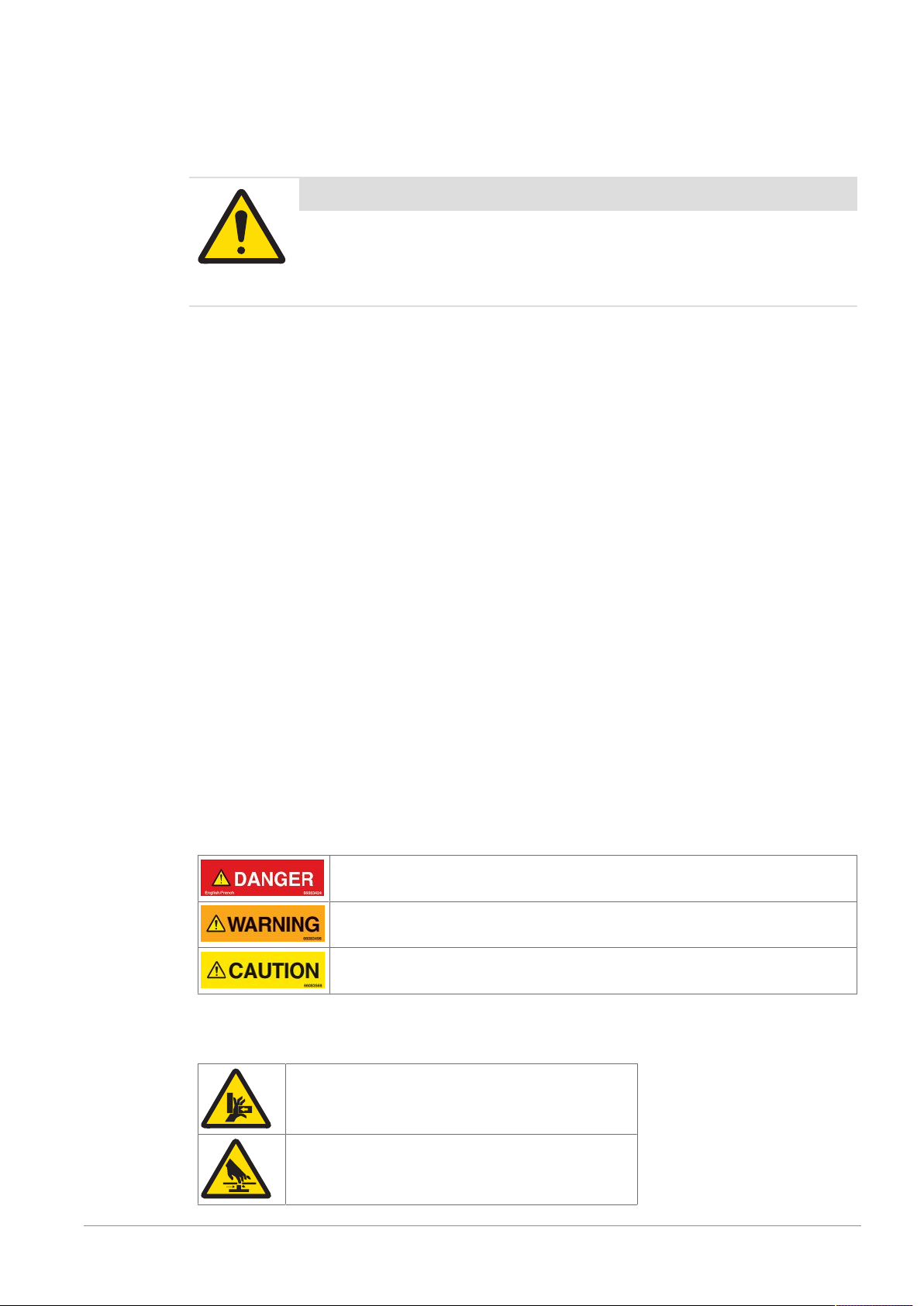
Important Safety Message
Read and understand all the safety information in the following sections as
well as the safety messages in the rest of this manual.
If you do not follow the safety information and messages, this may lead to property
damage and personal injury up to and including death.
2.1 Safety Labels and Notice Labels
The ISO3864 safety labels are installed at potentially hazardous areas on the equipment. They give special
safety-related notifications. The locations of these labels are given in the drawings supplied with your
equipment. There are three types of safety labels:
• Hazard notifications
• Mandatory procedures
• Prohibitive procedures
Additionally, NOTICE labels may appear on your equipment.
The meanings of the different kinds of labels are explained in the following sections.
Before you transport, install, operate or work on the equipment, find out about the location and meanings of
the labels. Maintain the labels so that they are clear of obstructions and are readable. Do not remove any
labels. Replace any label that is no longer readable.
2.1.1 Hazard Notifications
A hazard notification consists of the following:
• Hazard alert symbol (yellow triangle with black symbol)
• Signal word (DANGER , WARNING , or CAUTION )
• Special notifications related to the hazard (as required)
The signal word labels are attached next to the hazard alert symbol labels on the equipment.
2.1.1.1 Definitions of Signal Words
Signal words describe the level of risk of a particular hazard. The color of the safety label background
indicates the risk, as shown in the following table. The definitions of the signal words are based upon the
ISO3864 definitions.
DANGER (red): This signal word indicates an imminently hazardous situation which,
if not avoided, will result in death or serious injury.
WARNING (orange): This signal word indicates a potentially hazardous situation
which, if not avoided, could result in death or serious injury.
CAUTION (yellow): This signal word indicates a potentially hazardous situation
which, if not avoided, could result in minor or moderate injury.
2.1.1.2 Meaning of Hazard Alert Symbols
The following hazard alert symbols may be installed on your equipment.
Crushing
Shearing
XMV-TE - User Manual - Document Version A 7 / 38
Page 8
Cutting
Entanglement
Drawing-in, trapping
Impact
Ejection of parts
Abrasion, friction
High pressure fluid ejection
Loss of stability
Slipping, tripping
Electrical shock
Electrostatic
Hearing impairment
Arc flash
Optical radiation
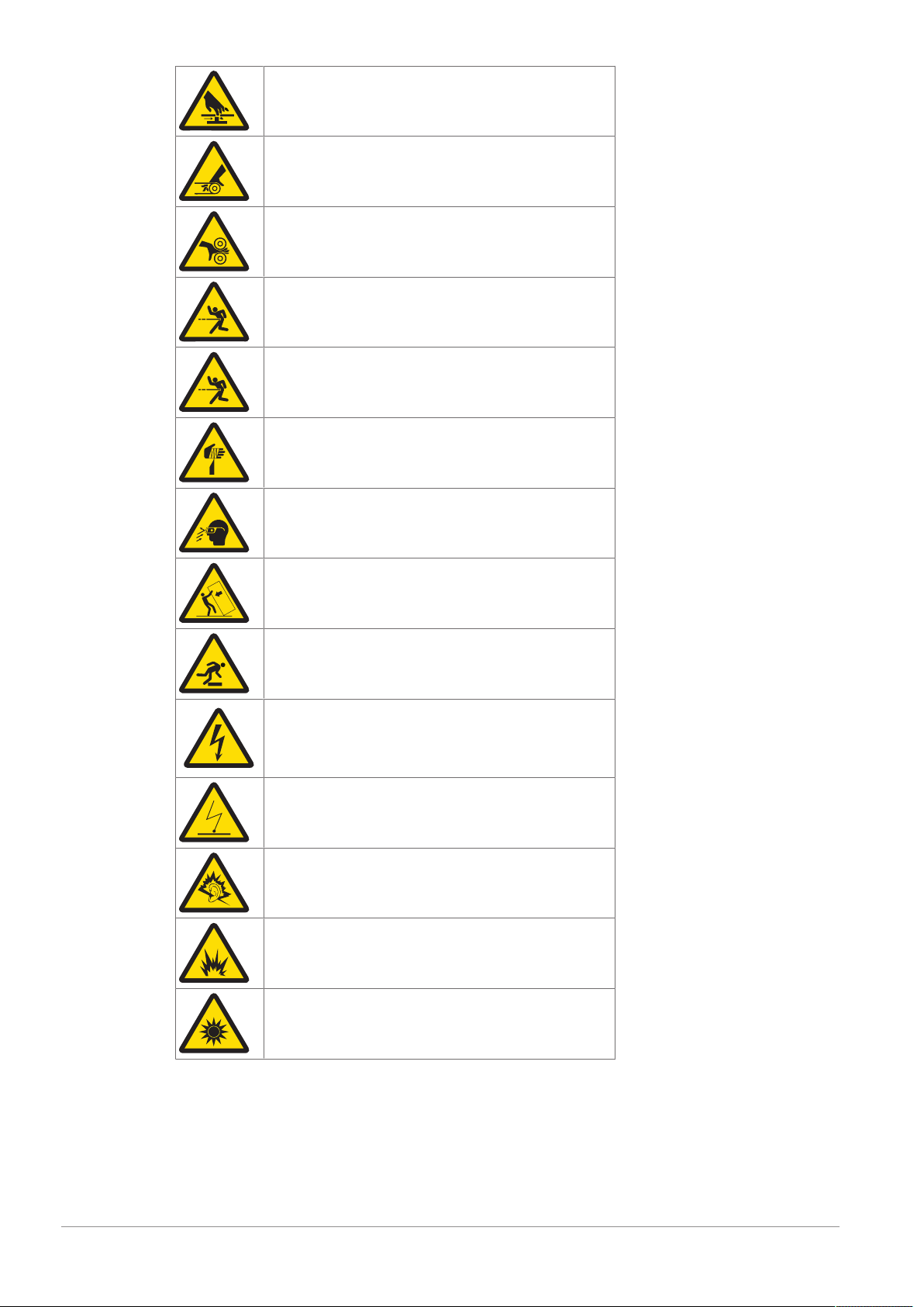
2.1.2 Mandatory Procedures
Mandatory procedures alert personnel to special, required actions. The round labels have blue backgrounds
and white symbols. The symbols describe the required action. The following table lists the mandatory
procedures labels which may be installed on your equipment.
8 / 38 XMV-TE - User Manual - Document Version A
Page 9
Read the manual
Read the technical manual
Wear ear protection
Lockout, tagout
Lift point
2.1.3 Prohibited Procedures
Prohibited procedures alert personnel to particular actions to avoid. The labels are round with a circular red
band and single diagonal cross bar. The black symbol describes the action to avoid. The following table
lists the prohibited procedure labels that may be installed on your equipment.
Do not operate without safeguards
Do not step on the equipment
2.1.4 Notice
The word NOTICE does not give safety information. It is still an important word to inform you of activities
that may harm the equipment or other property. The following definition is based upon the ANSIZ535
definition.
NOTICE (blue): This indicates important information that is not related to personal
injury which, if ignored, could result in damage to the equipment, damage to
property, malfunctions, erroneous results, or loss of data.
2.1.5 Note
The word NOTE: does not give safety information. It indicates useful supplementary information, hints, and
tips.
2.2 General Protective Procedures
Important Safety Message
Make sure that all personnel who work on or near the equipment are capable
of performing all operations in a safe way.
• Keep the manual in a convenient location near the equipment. Replace the manual if it becomes lost or
damaged.
XMV-TE - User Manual - Document Version A 9 / 38
Page 10

• Wear Personal Protective Equipment (PPE) in accordance with your plant's safety procedures.
• Understand the hazards of the equipment and the risks related to those hazards before working on or
near the equipment.
• Obey all safety procedures of the local plant.
• Do not wear loose clothing, jewelry, long hair, or anything that can become entangled with the
equipment.
• Be careful around the equipment to avoid hitting your head, arms, or other body parts against the
equipment. Be careful if the equipment is over your head.
• Be careful not to trip over cables or other parts of the equipment.
• Do not move quickly in the area around the equipment.
• Do not climb, hang onto, or use any of the part of the equipment as a support.
• Obey the lockout tagout (LOTO) procedures of the plant.
• If there is a safety-related malfunction when you are operating the equipment, press the emergency stop
device. Tell the responsible supervisor, and follow the applicable steps approved by your company to fix
the malfunction.
2.3 Safety Information for Various Activities
Important Safety Message
Read and understand all parts of the manual before using or working on any
equipment.
The following sections list safety information for particular activities or groups of activities. Refer to the
correct sections in the manual for more detailed instructions.
2.3.1 Transporting and Moving the Equipment
• Only transport or move the equipment if you have the applicable training as defined by your company.
• Your company has sole responsibility for the safe moving and transporting of the equipment.
• Use safe moving procedures during transporting to maintain stability and to prevent the equipment from
tipping or falling.
• Disconnect the electrical supply, the pneumatic supply, and the communication cables before you move
the equipment.
• Use the correct lifting devices. If you use a forklift, lift the equipment at the correct lift points as shown by
the blue lift point labels.
• Blue lift point labels are placed on the equipment to show recommended locations for lifting. These lift
point locations were tested with the manufacturer's forklift trucks. A qualified rigger must make sure that
the lift points are correct for your lifting equipment.
• When you lift the equipment by hand, obey the safe lifting procedures of your company.
2.3.2 Installing
Only install the equipment if you have the applicable training as defined by your company.
2.3.3 Operating the Equipment and Monitoring the Inspection Process
• Before beginning operation, make sure that the area is safe.
• Know the location and effect of each emergency stop button that controls the equipment.
• Do not operate the equipment without protective guards and doors in place.
• Do not reach into path of the products when any conveyors are in motion.
• Do not reach into the area around any sorting device, when the equipment is turned on.
• Make sure the safety circuit is working correctly.
• Do regular inspections of the equipment.
• If there is a fault or change in the equipment behavior, stop the equipment and inform responsible
personnel.
10 / 38 XMV-TE - User Manual - Document Version A
Page 11

2.3.4 Testing and Verifying the Equipment
Only do testing and verifying of the equipment if you have applicable training as defined by your company.
2.3.5 Maintaining, Cleaning and Sanitizing the Equipment
• Remove all power from the equipment before doing any work.
• Keep the equipment in good working order.
• Follow a preventative maintenance program.
• Replace parts when needed.
• Obey the lockout tagout (LOTO) procedures of the plant.
• Test (validate) the safety circuit after parts are replaced.
• Only use METTLER TOLEDO approved spare parts and accessories.
• Do not make any unauthorized modifications to the equipment.
• Replace safety labels if damaged, missing, or unreadable.
• Do a visual check of the equipment at least once during a shift to identify any visual damage or faults.
Report any equipment changes to the responsible supervisor immediately.
• When required for a hygienic production environment, do regular sanitizing of the equipment according
to your company's procedures.
• After cleaning or sanitizing, check all cables, connectors, and pneumatic hoses for leakage, loose
connections, rub marks and damage. Tighten, repair, or replace any faulty cables and air tubing, as
necessary.
2.4 Special Hazards
The following sections describe special instructions for equipment that may have special hazards.
2.4.1 Electricity
• Only work on the electrical systems if you have the applicable electrical training as defined by your
company.
• Keep all electrical enclosure doors closed. If the doors have locks on them, keep them locked.
• Remove all power from the equipment before doing any work.
2.4.2 Pneumatics
• Only work on the pneumatic system if you have the applicable training as defined by your company.
• Check pneumatic parts for visible damage.
• Before any repair or maintenance work, remove the pneumatic supply and relieve the pressure in the
pneumatic system parts.
• Make sure that there is a consistent pneumatic supply when you operate the equipment.
• If a pneumatic pipe becomes loose during the operation of the equipment, keep away from the loose
pipe.
2.4.3 Moving Parts
• Product inspection equipment moves automatically, intermittently and without notice. Some surfaces
may get hot. Do not place hands or any other body parts on or near the moving parts.
The following are examples of moving parts:
– Conveyor belts and rollers
– Rejectors and product diverters
– Motors
– Gearboxes
– Side grips
– Automatic position adjusters
– Encoders
– Pneumatic cylinder
XMV-TE - User Manual - Document Version A 11 / 38
Page 12

– Solenoids
• Only operate the equipment with all safeguards in place.
• Make sure that all safeguards are in correct operating condition.
• Do not climb, sit, stand, walk, or ride on the conveyor.
2.4.4 Rejectors
• Be aware around rejectors because they move quickly and without notice.
• Do not reach into the rejector area or reject bin while the rejector is operating.
• Make sure the rejector is installed correctly.
• Make sure the rejected products do not cause harm.
• Keep your eyes and other body parts away from air blast nozzles when the equipment is operating.
2.4.5 Noise
• Make sure that all noise-absorbing parts of the equipment are present and in the correct position.
• Wear hearing protection as directed by your local safety authority.
2.4.6 Strobe Lights
• Strobe lights can cause seizures in individuals with photosensitive epilepsy.
• Individuals with photosensitive epilepsy must not operate the equipment.
• Do not operate the equipment when excessively fatigued or after consuming alcohol.
• Do not look directly at the lights, especially at close distances.
• Avoid placing the equipment in areas with reduced lighting.
• If lights are inside of an enclosure, do not open the enclosure doors when lights are flashing.
2.4.7 Lights and Laser Sensors
• Do not stare directly at any lights or lasers.
• Avoid prolonged exposure to ultraviolet (UV) light, infrared (IR) light, and lasers.
12 / 38 XMV-TE - User Manual - Document Version A
Page 13

3 Equipment Overview
3.1 Equipment Function
The Tamper Evident XMV-TE offers a complete printing and print verification system for printing on cartons
combined with secure tamper-evident sealing. The feeding direction of the print and control station is from
left to right. Thereby the product will be forwarded into the print- and inspection area consisting of two
transfer conveyers. The product will be directed close to the printing head, so that the print job can be done.
After the application of the printing and the sealing with tamper-evident the product will be forwarded, seals
will be checked and the imprint will be inspected and evaluated with a Smart Camera.
The evaluation takes place by the means of the „Good-Principle”, this yields to it, that only products
evaluated as GOOD through all kinds of inspection will pass the equipment. All products which have been
found bad will be ejected (missing print), respectively the equipment will stop (no match). The ejection of
the products is realized by pressure controllable blowing nozzles, controlled by the PLC, which exactly
knows at each time where the products are. The ejection will be controlled via a ejection counter check
sensor (ECC), which checks, that no BAD product will pass to the downstream equipment, and that a
GOOD product really passes by to the downstream equipment.
3.1.1 Workflow XMV Tamper Evident
1. The product sensor first recognizes the product and with the encoders it can be tracked through the
system.
2. The printer then prints the desired codes and text onto the product.
3. Code and text is checked through the Smart Camera. Depending on the reading results (of Smart
Camera and Tamper Evident Unit), it will be ejected or transported to the outfeed of the system.
4. When the product reaches the correct position that is entered within the article setup, the PLC sends the
trigger to start the label applicator. One for the front side and one for the rear side.
5. The label applicator places the front and the rear label.
6. Two sensors (front/rear) recognize the partial application of the TE labels onto the product and send the
information to the PLC.
7. At the position of the first labels (front/rear) detection light barrier, the light barriers verify that the labels
(front/rear) are partially placed.
8. Mechanical sheet metals fold back the labels.
9. At the position of the second label detection light barriers, the light barriers verify that the labels are
folded back
10. If the Smart Camera has no good reading or the TE labels are not fully applied onto the product, the
product will be ejected.
XMV-TE - User Manual - Document Version A 13 / 38
Page 14

11. A countercheck sensor verifies the ejection process. If a rejection fails, the system stops and an error
message will be displayed.
3.1.2 Limitation of Workflow
If a product is checked with the camera and proofed to be good, PLM will immediately commission the
respective product (status = commissioned). If application of the tamper evident afterwards fails, the
product will be rejected, but the status of the product will remain commissioned.
Therefore it is very important to check all products within the reject bin for status. If the status is commissioned, the product has to be manually decommissioned (see user manual for PLM). If the status is already
decommissioned, no manual booking procedures have to be performed.
1 Product Input
P Printer
C Camera
2 PLM: Product will be commissioned
TE Tamper Evident
RB Reject Bin
3 PLM: Product has to be decommissioned
3.1.3 Possible label positions Tamper Evident
Front top, rear top
Front bottom, rear bottom
14 / 38 XMV-TE - User Manual - Document Version A
Page 15

Front top, rear bottom
Front bottom, rear top
XMV-TE - User Manual - Document Version A 15 / 38
Page 16

3.2 Equipment Description
1 HMI – Human Machine Interface 15 Output conveyor motor
2 UPS indicator light 16 Input conveyor motor
3 Bypass key switch 17 HMI Display TE Front
4 USB interfaces 18 TE Label Roll Front
5 Indicator light 19 TE Label Roll Rear
6 Control cabinet 20 Lateral adjustment for the entire system
7 "Disconnect" switch* 21 HMI Display TE Rear
8 Handscanner 22 Lateral adjustment for camera and printer
9 Pneumatic unit 23 Smart Camera
10 Rejection system 24 Print heads
11 Output conveyor 25 Height adjustment for camera and printer
12 Countercheck light barrier 26 Input conveyor
13 Foot screw (adjustable) 27 Emergency stop button
14 Rejection bin with lock
16 / 38 XMV-TE - User Manual - Document Version A
Page 17

1 HMI – Human Machine Interface
The HMI is the interface which you need to operate the equipment. The HMI is connected to the IPC where
either the PCE Line Manager (PLM) software or a virtual network computing (VNC) connection to the PLM
software runs.
2 UPS (uninterrupted power supply) indicator light
The UPS (uninterrupted power supply) indicator light shows the status of the UPS:
On UPS working
Off UPS not working
3 Bypass key switch
The bypass key switch enables the emergency run. When the emergency mode is enabled, the conveyers
run in a pre-defined speed. For the emergency mode, only power is required, no other components such as
the PLM software are needed. This ensures that you can run the conveyors in the emergency mode even if
other components broke down.
4 USB interfaces
Usage: To connect external USB devices to the built-in IPC (industrial PC).
5 Indicator light
The indicator light provides visual and audible signals of the state or process event to equipment operators
and technicians:
Red (steady) Equipment has stopped. This can be the case either
when the equipment detects a fatal error or when such
an error has been solved and the equipment has not
been re-started again.
Yellow (flashing) Warning
Green (steady) Equipment runs in production mode
Green (flashing) Jam
6 Control cabinet
The control cabinet contains the following electronic components:
• Main power supply
• 24V power supply
• IPC
• PLC
• Print controller
7 "Disconnect" switch
The "Disconnect" switch connects/disconnects the main power of the equipment. It may be mounted in
different positions according to the units design.
8 Handscanner
The scanner reads machine-readable codes. You can configure the scanner according to the equipment
configuration. For configuration instructions, refer to the PCE Line Manager User Manual.
9 Pneumatic system
This is the pneumatic unit for the whole system.
10 Rejection system
If one of the print inspection devices sends the signal of a bad reading, the rejection system ejects the
products. Possible configurations:
Use case Configuration
For small / light products Blowing nozzles
For big / heavy products Pusher cylinder
For combined rejection system / switchable Blow pusher
11 Output conveyor
After printing, inspecting and sorting, the good products leave the equipment via the output conveyor belt.
XMV-TE - User Manual - Document Version A 17 / 38
Page 18

12 Countercheck light barrier
The countercheck light barrier checks whether the product passes the light barrier at the correct position after
the print inspection devices have checked the print quality of the product. If the print inspection devices have
failed to eject one bad product, the countercheck light barrier produces an error.
13 Foot screw (adjustable)
You can adjust the equipment with the four foot screws.
Fine adjustments to the conditions of use are essential when installing the system. When the equipment is
installed, these fine adjustments are adapted by a service technician to the surrounding conditions. Only
trained service technicians may perform fine adjustments. To make these fine adjustments, detailed professional knowledge is necessary.
14 Rejection bin with lock
The equipment contains a rejection bin, which can be locked with a key. In this rejection bin all the rejected
products are gathered. The rejection bin is made out of acrylic glass.
15 Output conveyor motor
The motor is part of the conveyor system.
16 Input conveyor motor
The motor is part of the conveyor system.
17 HMI Display TE Front
The HMI is the interface to control the Tamper Evident unit of the front.
18 TE Label Front
This is the label roll for the Tamper Evidents of the front.
19 TE Label Rear
This is the label roll for the Tamper Evidents of the rear.
20 Lateral adjustment of the entire system
With the lateral adjustment, you can move the complete equipment forwards and backwards.
21 HMI Display TE Rear
The HMI is the interface to control the Tamper Evident unit of the rear.
22 Lateral adjustment for camera and printer
By using the lateral adjustment, you can move the camera and the print heads of the equipment forwards
and backwards to handle different sized cartons. Camera and print heads can only be moved simultaneously, therefore it is not necessary to adapt the camera field of view to the print heads.
23 Smart Camera
The Smart Camera system consists of an intelligent camera with integrated signal processor and a software
which is able to control different characteristics. Furthermore, the camera hardware contains a memory, a
network interface, an optical component and illumination.
24 Print heads
The print heads of the continuous ink jet printer are part of the marking system and belong to the main
components of the XMV-TE. With these print heads you can print alphanumeric texts, bar codes, 2D codes,
Data Matrix codes and logos with a print height of 12.7 mm per cartridge. If you require greater print
heights, you can cascade several print heads.
25 Height adjustment for camera and printer
By using the height adjustment, you can move the camera and the print heads on the front side of the
equipment up and down independently from the conveyor height. Camera and print heads can only be
moved simultaneously, therefore it is not necessary to adapt the camera field of view to the print heads.
26 Input conveyor
The conveyor belts insure a smooth and safe transport of the products. The conveyor belts are free from
maintenance.
27 Emergency stop button
If you push the emergency stop button, the conveyor belts of the XMV-TE stop immediately. If you push the
emergency stop button, connected equipments next to the XMV-TE stop as well.
18 / 38 XMV-TE - User Manual - Document Version A
Page 19

3.3 Equipment Options
3.3.1 Overview of Optional Mechanical Equipment
The system can be combined with different types of optional equipment. The following accessory options
are offered:
• Full housing with door and safety switch
• Different types of rejectors:
– High-performance double air nozzle
– Pusher
– Blow-pusher
• Different types of additional in-feed conveyors incl. guiding rails:
– 400mm
– 600mm
– 800mm
– 1200mm
• Different types of spare part kits
3.3.2 Full Housing
With the acrylic housing option, the risk of injury is minimized. The cover is protected with safety guards
against unauthorized opening, because it is locked during the running production.
Installation
1 Place the cover over the system.
2 Make sure that the cover does not touch the belt.
3.3.3 Rejection System Options
The XMV-TE is available with different types of rejection systems, depending on the weight of your product.
Available options are:
Use case Configuration
For small / light products Blowing nozzles
For big / heavy products Pusher cylinder
For combined rejection system / switchable Blow pusher
The rejection system is pre-configured. No additional configuration is necessary.
3.3.4 Conveyor Options
Different types of additional in-feed conveyors including guiding rails, and optional in-feed conveyors are
available for the XMV-TE. You can purchase the system with different sizes of the conveyor belts:
• 400mm
• 600mm
• 800mm
• 1200mm
The electrical connection for the conveyor belt is provided by the XMV-TE. When production is started by the
PCE Line Manager software, the in-feed conveyor starts running simultaneously. You can start the conveyor
as well when the machine runs in bypass mode. To adjust the guiding rails, unscrew the knurled screws
and move guiding in desired position. After positioning, fasten the screws to fix the guiding rails.
You can adjust the top belt to the size of your product. For instructions on how to adjust the top belt, refer to
chapter [Adjusting the Input Conveyor}Page24].
XMV-TE - User Manual - Document Version A 19 / 38
Page 20

4 Transporting, Moving, and Storage
WARNING
Lift the system only under the supervision of a competent person who has
sufficient and applicable training.
WARNING
Obey the applicable safety regulations at all times during lifting operations.
NOTICE
METTLER TOLEDO accepts no liability for damage to the system caused by
using incorrect lifting procedures or inadequate lifting equipment.
NOTICE
The equipment can be considerably damaged by shocks or by dropping. Be
careful when moving the equipment and do not tip it or drop it.
4.1 Transporting the Equipment
WARNING
If the equipment is not properly secured when transporting, it may tip over or
drop. This may cause serious injury or death.
Only qualified personnel are allowed to transport the equipment. Secure the
equipment and keep it upright when transporting. Use an appropriately sized
forklift or similar cart.
Follow these instructions when transporting the equipment in its original packaging:
• Do not unpack the equipment from its crate or other packaging before reaching the location where it is
to be installed.
• Use lifting and transporting equipment that has the appropriate loading capacity.
• Do not tilt or drop the equipment while transporting.
• If using a forklift truck, pick up and move the crate so that the shipping label or the text that reads "LIFT
THIS SIDE ONLY" (or similar text) faces toward the front of the forklift truck.
4.2 Storing the Equipment
Follow these instructions for storing the equipment:
• Until the equipment is installed, leave it upright in its original crate or packaging.
• Store the equipment in a clean, dry, climate-controlled room. This protects the equipment from physical
damage and harmful exposure to dirt, dust and moisture.
• Keep all electronic parts in the protective, anti-static pouches until they are used.
If you do not operate the system for some time and want to store it until you use it again, you need to do
the steps that follow:
1 Clean and sanitize the system according to the procedures of your company.
2 Make sure that every part of the system is dry.
3 Wrap the system in cling film or a similar packaging material.
4 Add applicable moisture-absorbing packages, such as desiccant (silica gel) inside the wrapped system.
20 / 38 XMV-TE - User Manual - Document Version A
Page 21

5 Store the system in a dust-free and dry location in accordance with the environmental conditions below:
ð Temperature range: -10°C (14°F) to 50°C (122°F)
ð Relative humidity: 30% to 85% (non-condensing)
If you want to store the system while it is still packed in the crate after you have received it, follow step 5.
4.3 Unpacking the Equipment
Pharmacontrol Electronic GmbH supplies the equipment in a crate wrapped in plastic wrapping and
banding.
Pharmacontrol Electronic GmbH supplies the equipment attached to a wooden pallet. The pallet may or
may not be inside a wooden or cardboard crate.
Only unpack the equipment after it has reached its final destination.
NOTICE
Take care not to disturb the positioning of the components when removing the
wrapping.
Follow these steps to unpack the equipment:
1. Remove the plastic wrapping and banding.
2. Remove the sidewalls. Then, remove the top of the crate, wood support pieces, and the corner posts.
3. If applicable, remove and discard any blocks and metal brackets that attach the casters or adjustable
feet to the pallet.
4. Loosen and remove the nuts on the bolts which attach the machine feet to the crate. Then, remove the
bolts.
5. Follow the procedure in Moving the Equipment and Setting it in Place to lift the equipment off the pallet
and set it in place.
6. Carefully remove all shrink wrap, bubble wrap, and plastic strapping that may be around the
components of the equipment.
7. Bolts may loosen during shipment. Check to make sure that all of the bolts on the equipment are tight
and secure. Tighten any loose bolts.
8. Recycle or discard the packaging materials.
4.4 Moving the Equipment and Setting it in Place
CAUTION
Improper lifting of the equipment can cause personal injury.
Always observe your company‘s safe lifting procedures if lifting the
equipment by hand.
NOTICE
Take care that the prongs of the forklift do not damage the equipment. Use lift
straps if needed.
Whenever possible, use a forklift truck to lift and move the system. Alternatively, use powered lifting
equipment with straps or lifting tackle.
If using a forklift truck or similar lifting equipment, lift the equipment at the lift point labels.
A lift point label looks like this:
If there are no lift point labels on the equipment, or you are unable to use a forklift truck or other lifting
device, move the equipment by hand using at least three people. Lift the equipment by the frame. Do not lift
by the conveyors, motors or other components. Always observe your company's safe lifting procedures.
XMV-TE - User Manual - Document Version A 21 / 38
Page 22

Allow enough space at the front and the back of the system so that commissioning and maintenance staff
can easily get access to components. Whenever possible, allow a minimum 1 meter of free space at the
front of the system and 1 meter at the back of the system.
Set the equipment in place gently. Do not drop or tilt the equipment.
4.5 Preparing for Transporting (After First Installation)
If the equipment needs to be transported to new location after the first installation, follow this procedure.
NOTICE
The cameras are sensitive precision measuring instruments. The cameras will
be considerably damaged by shocks or by dropping.
Ensure that any protruding parts such as cameras, photo eyes, etc. are sufficiently protected.
1. Decommission the equipment according to the procedure in the Decommissioning chapter of this
manual.
2. Remove the following components if they are included with your equipment:
– Rejector
– Regulator and solenoid valve
– Encoder
– Reject verify
– Detect sensor and reflector
3. Wrap the removed components in bubble wrap and place them in a box (or boxes). Keep these boxes
together with the rest of the equipment.
4. Unbolt the equipment from the floor.
5. Gather the loose wires and coil them neatly in bundles. Attach the bundles to the frame with tie wraps.
6. Carefully wrap any cameras, sensors and other delicate components in bubble wrap. Secure with tape.
7. Wrap the equipment in plastic strapping if it is to be transported by vehicle to a new location.
8. Lift the equipment onto the crate base.
9. Bolt the equipment to the base of the crate.
10. Assemble the crate, and wrap it in plastic banding and shrink wrap.
22 / 38 XMV-TE - User Manual - Document Version A
Page 23

5 Installation
Connect the XMV-TE to the power supply. Consult the XMV-TE nameplate to check the required input
voltage.
The PCE Line Manager (PLM) software is installed on the XMV-TE before delivery. Adapt the PLM software
according to the desired formats. Take the necessary steps detailed in the PLM User Manual.
XMV-TE - User Manual - Document Version A 23 / 38
Page 24

6 Operation
Operating the XMV-TE is done via the PCE Line Manager (PLM) software. For detailed instructions on how to
operate systems via the PLM software, refer to the PLM Manual.
6.1 Using the Emergency Stop Button
In the event of any jam, blockage, or other unintended machine stop, no one should enter the conveyor,
rejector, or other portion of the system where a hazard is present, before de-energizing the hazard area(s)
where entry is required. The means to de-energize (opening of movable guard, e-stop, LOTO, etc.) is
determined by the user's local health and safety personnel, based on the user's task-based risk assessment
and local safety practices.
6.2 Adjusting the Input Conveyor
The input conveyor belt system either with a top and bottom belt or with a side grip provides optimal
product guiding. You can adjust the top belt to prevent that products slip or drift through the top and bottom
belt.
Adjusting the Top Belt
To adjust the height of the top belt to the size of your product, follow these instructions:
1 Turn the hand wheel and set the pass-through size to the height or width of the product.
2 Define the pass-though size adequately: The pass-through size setting should allow the product to be
gripped securely and moved further along the conveyor, but without being crushed.
Top and Bottom Belt
6.3 Adjusting the Rejection System for the Product's Weight
The rejection system ejects "bad" products. Three possible configurations of the rejection system are
available and need to be ordered when purchasing the XMV-TE:
Use case Configuration
For small / light products Blowing nozzles
For big / heavy products Pusher cylinder
For combined rejection system / switchable Blow pusher
The rejection system is pre-configured. No additional configuration is necessary. However, depending on
your product's material, weight and the speed of the conveyors, you may adapt the air pressure of the
rejection system. For blowing nozzles, the air pressure must be between 3 bar and 6 bar.
6.4 Starting Production
To start the production of a product, follow these instructions:
Preconditions:
• All devices (cameras, printers etc.) are configured correctly and work properly.
• A lineformat is already created.
• The work order is assigned to a lineformat.
To operate the XMV-TE:
• Turn on the system using the Disconnect button. The PCE Line Manager software starts automatically.
24 / 38 XMV-TE - User Manual - Document Version A
Page 25

• Log on as a user with appropriate user rights. For details on PLM user rights, refer to the PLM User
Manual.
• Switch to production screen.
• Start production via order.
• Select and start work order.
6.5 Ending Production
To finish the production of a product, click the “Finish” button in the PCE Line Manager (PLM) software on
your touch monitor. For detailed instructions on how to operate systems via the PLM software, refer to the
PLM Manual.
The XMV-TE is then ready for further tasks.
6.6 Switching down the Equipment
Preconditions:
• Production is currently not running
• Switch off system by using "Disconnect" button.
The XMV-TE shuts down in a controlled way defined by the UPS.
XMV-TE - User Manual - Document Version A 25 / 38
Page 26

7 Cleaning
These instructions give staff, who clean and sanitize the system, information about the materials and
finishes of the equipment.
The system user always has full and complete discretion, responsibility, and liability for determining the
suitability of all cleaning and sanitization agents, protocols, and processes related to the system.
Regular cleaning is very important to keep good system operation. Proper cleaning and sanitization of
equipment and work surfaces can do as follows:
• Remove dirt and food material that harbor microorganisms
• Help to reduce bacteria, including pathogens
• Help to reduce risks of cross-contamination
• Extend the operational life of the system
WARNING
Before you clean the system, wear sufficient protective clothing and hand
protection as recommended by the manufacturer of any detergents used.
7.1 Using Detergents
Some components of the system can be susceptible to attack by some detergents or disinfectants. This can
be detrimental to the operation of the system and can also shorten the effective life of the system.
Take care when you select detergents and disinfectants for use on various surfaces of the system (see information later in this section). On the basis of pH value, detergents can be classified as follows:
• Acid detergents – Detergents with a pH value below 4 are potentially damaging to the equipment. They
are not suitable for daily cleaning so restrict their use to once a month at most, followed by a thorough
rinsing process with clean water.
• Neutral detergents – Use preferably neutral detergents with a pH value of 7.
• Alkaline detergents – Alkaline detergents with a pH value between 7 and 12 are normally applicable to
everyday cleaning.
CAUTION
If any of the above detergents are mixed with chlorine or a strong oxidizing
agent (used to break down proteins and some vegetable staining such as
carrot), then take special care to use the correct concentration and to
thoroughly rinse it off
Typical concentrations must not exceed 2%. Rinse off the concentrations within the specified time, typically
10 to 15 minutes and not more than 20 to 30 minutes. Never let the concentrations dry on the surface.
Most detergents are sprayed on as a gel or foam, so it is important to thoroughly rinse the detergent off.
This also applies to the disinfectant because, if it is left to dry on a surface, it increases the effect of the
oxidizing agent in the detergent.
Machine surfaces
• Stainless steel - Use mild, non-abrasive acidic and alkaline cleaners. Do not use hydrochloric acid or
chlorides.
• Plastic - More corrosion-resistant than stainless steel, plastics are resistant to chlorine but can crack or
cloud from prolonged exposure to strong acidic or alkaline cleaners, and they are easily scratched. Use
mild, non-abrasive acidic and alkaline cleaners.
7.2 Cleaning Procedure
You need to do the cleaning procedure consistently and in accordance with your company's appropriatelydefined cleaning protocols. The user has full and complete discretion, responsibility, and liability to
establish and do its cleaning protocols. The user can develop cleaning protocols based on the specific
application for which the system is used.
26 / 38 XMV-TE - User Manual - Document Version A
Page 27

7.3 Visual Inspection and Cleaning of the System
Recommended Inspection
Interval
Daily Perform a general visual inspection.
What Needs to Be Done?
WARNING
Cleaning the system when it is hot may cause severe damage.
Only clean the system with moisture when it is cold.
Before cleaning, allow the drive motors to cool down completely.
WARNING
Never use a high pressure jet to hose down the system.
Do not use caustic cleaning agents containing solvents to clean the system and the
terminal. Never use pure alcohol or concentrated acid or lye.
Use particular care when cleaning in order to avoid damage and, above all, to prevent
water from entering the system.
Clean the system and terminal using soft cloths dampened with a mild solution of soap and water or a
commercially available glass and plastic cleaner.
7.4 Cleaning the Cover
Clean the cover using soft cloths dampened with a mild solution of soap and water or a commercially
available glass and plastic cleaner.
7.5 Restarting the System after Sanitization
When you have finished the sanitization process, remove all lockout and tagout devices and return the
system to its normal operation condition. Before you restart the system, make sure that all safety devices
are back in their original positions and correctly fastened. For example, if you removed any guards for
cleaning, make sure that you reinstall them.
WARNING
NEVER start the system without all original safety features in the correct
locations.
Re-engage all interlocks before you start the system. On some systems, a blue fault lamp in the SYSTEM
RESET button comes on until all interlocks are engaged.
After cleaning, check all cables connectors and compressed air hoses for leakage, loose connections, rub
marks, and damage. Tighten, repair or replace any faulty cables and air hoses, as necessary.
Disclaimer: The end user shall at all times keep full and complete discretion, responsibility, and liability for
determining the suitability of all cleaning and sanitization agents, protocols, and processes of whatsoever
kind or type related to the equipment. At the end user's request, METTLER TOLEDO shall provide the end
user with information about the materials and finishes which comprise the equipment, such as the grade of
stainless steel.
XMV-TE - User Manual - Document Version A 27 / 38
Page 28

8 Maintenance
8.1 Maintenance of the Gaskets
Recommended Inspection
Interval
Monthly • Perform a general visual inspection.
Make sure that gaskets on covers such as flaps and doors, or also on (optional) glass light covers, are in
good condition. If the gaskets need to be replaced, contact the METTER TOLEDO Service. You find contact
details for the METTLER TOLEDO Service at Service.
What Needs to Be Done?
• If necessary, replace the gaskets.
8.2 Maintenance of the Rejection System
Compressed air must be free of contaminants, i.e. it must be clean and dry, otherwise the performance of
pneumatic devices (e.g. ejectors, sorting switches) can be impacted and pneumatic parts may undergo
premature wear.
WARNING
Risk of injury
Turn off the compressed air supply before starting work on the pneumatic cylinder or
solenoid valve, or prior to loosening any screw connections, connectors, etc.
Recommended Inspection
Interval
Weekly • Perform a general visual inspection of the rejection
What Needs to Be Done?
system.
• Inspect the compressed air system for contaminants,
leaks in the hoses and in the connections of the
hoses.
Replace damaged or worn connecting hoses
immediately.
• Check the pressure gauge for the correct pressure
setting: at least 3 bar, depending on the product
(maximum of 6 bar!).
Checking the Sight Glass
Regularly check the sight glass of the water separator on the device's compressed-air supply.
Recommended Inspection
Interval
Monthly • Perform a general visual inspection of the sight
1 If condensate has accumulated in the sight glass, turn off the compressed air supply, unscrew the drain
plug at the bottom of the sight glass, and let the water drain into a container.
2 Then, screw the plug back in and tighten it by hand.
What Needs to Be Done?
glass.
• Drain the condensate.
8.3 Maintenance of the Conveyor Belts
DANGER
RISK OF FATAL INJURY FROM ELECTROCUTION
Before starting any work, i.e. prior to cleaning or maintenance, the system must be
disconnected from the power supply by a qualified electrician.
28 / 38 XMV-TE - User Manual - Document Version A
Page 29

The cleaning steps and simple maintenance tasks described below can be performed by operating
personnel with sufficient technical experience.
Cause or Recommended
Inspection Interval
Excessive wear of top and
bottom belt
Significant elongation of the
belts
Weekly Make sure that the top belt and bottom belt are clean
Daily Perform a general visual inspection of the conveyor
Clean the conveyor belts (and, if installed, the transition plates) using soft cloths dampened with a mild
solution of soap and water or a commercially available glass and plastic cleaner. Keep the conveyor belts
and any installed transition plates clean. This also keeps the metal slider bed plates under the belts clean
and smooth.
Frequently check any installed safety devices to ensure that they are correctly positioned and in good
condition.
What Needs to Be Done?
Have equipment replaced by Technical Service.
and do not show any signs of wear.
If necessary, correct the setting of the top and bottom
belt.
belts.
Replace worn belts immediately.
NOTICE
There are no points on the conveyors that require lubrication.
WARNING
Risk of injury
Never loosen or remove the fastening screws of the conveyor belt on the columnar base
frame.
CAUTION
Conveyor belt grinding causes increased wear and excessive vibrations.
Avoid contact between conveyor belts and any safety devices or transition plates installed.
Checking the Tension of the Conveyor Belts
Over time, most belt types will stretch as a result of use.
Recommended Inspection
Interval
Weekly Check the conveyor belts for a tight fit.
What Needs to Be Done?
NOTICE
The tension of elastic belts (rubber belts) does not need to be checked in this manner
since it is not possible to tauten them using the belt tensioners. Belts of this type must be
replaced when they show visible signs of wear or a noticeable loss of elasticity.
The following indicators can be used to monitor the belt tension:
1 Switch off the conveyor belts.
2 If it is possible to lift the belt's edge section by sliding one fingertip under the belt at about the midpoint
of the conveyor, then the belt is still sufficiently taught.
XMV-TE - User Manual - Document Version A 29 / 38
Page 30

Sufficient belt tension (one-finger rule)
If it is possible to slide two fingers under the belt, then the belt is just barely taut enough.
Belt tension still sufficient (two-finger rule)
Slippage (drift) under normally occurring loads (product weights) is a sign that there is too much slack in
the belt.
Tensioning the Conveyor Belt
NOTICE
The belts should only be tensioned on the belt-tensioning devices as much as
is absolutely necessary to keep them from slipping (no drift) under normally
occurring loads. Excessive tautening results in rapid wear of the belts and
deflection pulley bearings.
• The conveyor belt must run centered and straight.
• It is not necessary to disassemble the belt frame in order to tension the conveyor belt.
METTLER TOLEDO recommends having Technical Service conduct an annual inspection of the drive system
(pulleys, belts, etc.).
A tensioning screw for tensioning the conveyor belt is located on each side of the idler (on the side panel of
the belt frame).
Tensioning screws
30 / 38 XMV-TE - User Manual - Document Version A
Page 31

Turn both belt-tensioning screws evenly (initially one full turn per screw) in a clockwise motion. This moves
the deflection pulley slightly further outwards, thereby increasing the tension of the belt. If necessary, repeat
the procedure.
Important Safety Message
If tensioning is not performed evenly on both sides, then the belt will not run
centered and straight.
8.4 Maintenance of the Rejection Bin
Clean the rejection bin using soft cloths dampened with a mild solution of soap and water or a commercially available glass and plastic cleaner.
8.4.1 Exchanging a Damaged Rejection Bin
The rejection bin collects rejected products. If the rejection bin is damaged, replace it with a new one.
Important Safety Message
Only use METTLER TOLEDO approved spare parts and accessories.
For detailed information on how to order spare parts, refer to chapter Service.
To replace a damaged rejection bin, follow these instructions:
1 Loosen the four or six M5 or M6 hex bolts (depending on the design) using a (metric) size-8 or size-10
wrench and remove them from the fastening plate. Be careful not to lose any of the washers.
2 Take off the damaged rejection bin.
3 Position the new rejection bin in front of the fastening plate so that the four/six holes on the rear panel of
the bin line up perfectly with the four (six) threaded holes on the fastening plate. This step is best done
by a second person.
4 Insert the four/six hex bolts – using a washer for each bolt – into the four/six holes on the rear panel of
the bin and tighten the bolts hand-tight.
Important Safety Message
Manually tighten the bolts to a sufficient extent with a wrench, but refrain
from applying excessive force, since the bin is made of plastic (acrylic).
8.5 Maintenance of the Toothed Belt
Recommended Inspection
Interval
Monthly or at least every
250 hours of operation
What Needs to Be Done?
Immediately replace worn toothed belts.
Important Safety Message
Make sure that the toothed belt does not grind against anything, that no teeth
are missing on the inside of the belt, and that the belt is not dirty. If
necessary, replace the toothed belt.
Make sure that the toothed belts are in good condition. If the toothed belts need to be replaced, contact the
METTER TOLEDO Service. You find contact details for the METTLER TOLEDO Service at Service.
XMV-TE - User Manual - Document Version A 31 / 38
Page 32

8.6 Maintenance of the Light Barriers
Recommended Inspection
Interval
Weekly Perform a general visual inspection for dust, dirt, finger-
Weekly Perform a general visual inspection on th cables and
What Needs to be Done?
prints or moisture condensation. If necessary, clean the
light barriers.
check whether cables are tightly screwed. If they are not,
tighten the cable screws.
Important Safety Message
Always keep the light barriers (light sensor, photocells, and if necessary, the
reflectors) clean. Dust, dirt or moisture condensation on the optical parts may
lead to malfunctions.
If necessary, clean the light barriers using a soft, slightly damp towel or with cotton
swabs.
32 / 38 XMV-TE - User Manual - Document Version A
Page 33

9 Technical Data
Technical Data XMV TE
Throughput Max. 300* (pieces / minute)
Height of folded box 20 to 100 mm (observe the printing height)
Pass width 75 to max. 200 mm
Printer resolution max. 600 dpi
Camera resolution max. 1550 x 1200 pixels
Roller centres, outfeed conveyor 400 mm (Default)
Belt width, infeed conveyor 40 mm (Default)
Belt width, outfeed conveyor 200 mm (Default)
Standard sorting / rejecting device air jet, pusher for heavy duty
Line height 850 mm +/- 30 mm (other heights on enquiry)
TE Label Type & Material PP-FOIL TR. GL. 80G (ACRYL) or PET TRANS MIT
VOID
TE Label format Min. 20 x 20 mm (B x H) - max. 40 x 40 mm
(BxH)
TE Placing accuracy +/- 0.8 mm
XMV-TE - User Manual - Document Version A 33 / 38
Page 34

10 Spare Part Kits
For XMV TE the following spare parts are available:
Article Number Description
1.01.1400.60.0009 XMV TE - Spare Part Kit - Basic Kit
Outfeed conveyor:
• 1 transport belt
• 1 tooth belt 2MR-130-9
• 1 drive roller
• 1 idle roller
TBB conveyor:
• 2 transport belts
• 2 tooth belts
• 2 drive rollers
• 2 idle rollers
For the Printer:
• 1 printer cartridge
1.01.1400.60.0010 XMV TE - Spare Part Kit - Uptime Kit
Outfeed conveyor:
• 1 transport belt
• 1 tooth belt 2MR-130-9
• 1 drive roller
• 1 idle roller
TBB conveyor:
• 2 transport belts
• 2 tooth belts
• 2 drive rollers
• 2 idle rollers
For the Printer:
• 1 printer cartridge
Motors:
• Motor for outfeed conveyor
• Motor for TBB conveyor
1.01.1400.60.0011 XMV TE - Spare Part Kit – Electronics Kit
• 2 x motor
• 1 x LPB XRTC
• 1 x Motor Connection Board
• 1 x printer head
• 1 x Light barrier
• 5 x fuses
34 / 38 XMV-TE - User Manual - Document Version A
Page 35

Article Number Description
1.01.1400.60.0012 XMV TE - Spare Part Kit - Complete Kit
For the conveyor:
• 3 x full flat belt
• 3 x toothed belt
• 3x drive roller
• 3x idle roller
For the Printer:
• 1 printer cartridge
Electrical/Electronic components:
• 2 x motor
• 1 x LPB XRTC
• 1 x Motor Connection Board
• 1 x printer head
• 1 x Light barrier
• 5 x fuses
XMV-TE - User Manual - Document Version A 35 / 38
Page 36

11 Disposal
In conformance with the European Directive 2012/19/EU on Waste Electrical and
Electronic Equipment (WEEE) this device may not be disposed of in domestic waste. This
also applies to countries outside the EU, per their specific requirements.
Please dispose of this product in accordance with local regulations at the collecting point
specified for electrical and electronic equipment. If you have any questions, please contact
the responsible authority or the distributor from which you purchased this device. Should
this device be passed on to other parties (for private or professional use), the content of
this regulation must also be related.
Thank you for your contribution to environmental protection.
36 / 38 XMV-TE - User Manual - Document Version A
Page 37

Page 38

Pharmacontrol Electronic GmbH
Gernsheimer Strasse 2
64673 Zwingenberg, Germany
Tel. +49 6251 8545-0
Fax +49 6251 8545-111
www.mt.com
Subject to technical changes.
© Pharmacontrol Electronic GmbH 12/2017
XMV-TE - User Manual - Document Version A
www.mt.com/pce
For more information
 Loading...