

Mettler Toledo WXS205DU/15, WXSS204, WXS205DUV/15, WXS204V/15, WXSS205DU Instructions For Installation And Operation Manual
...Page 1
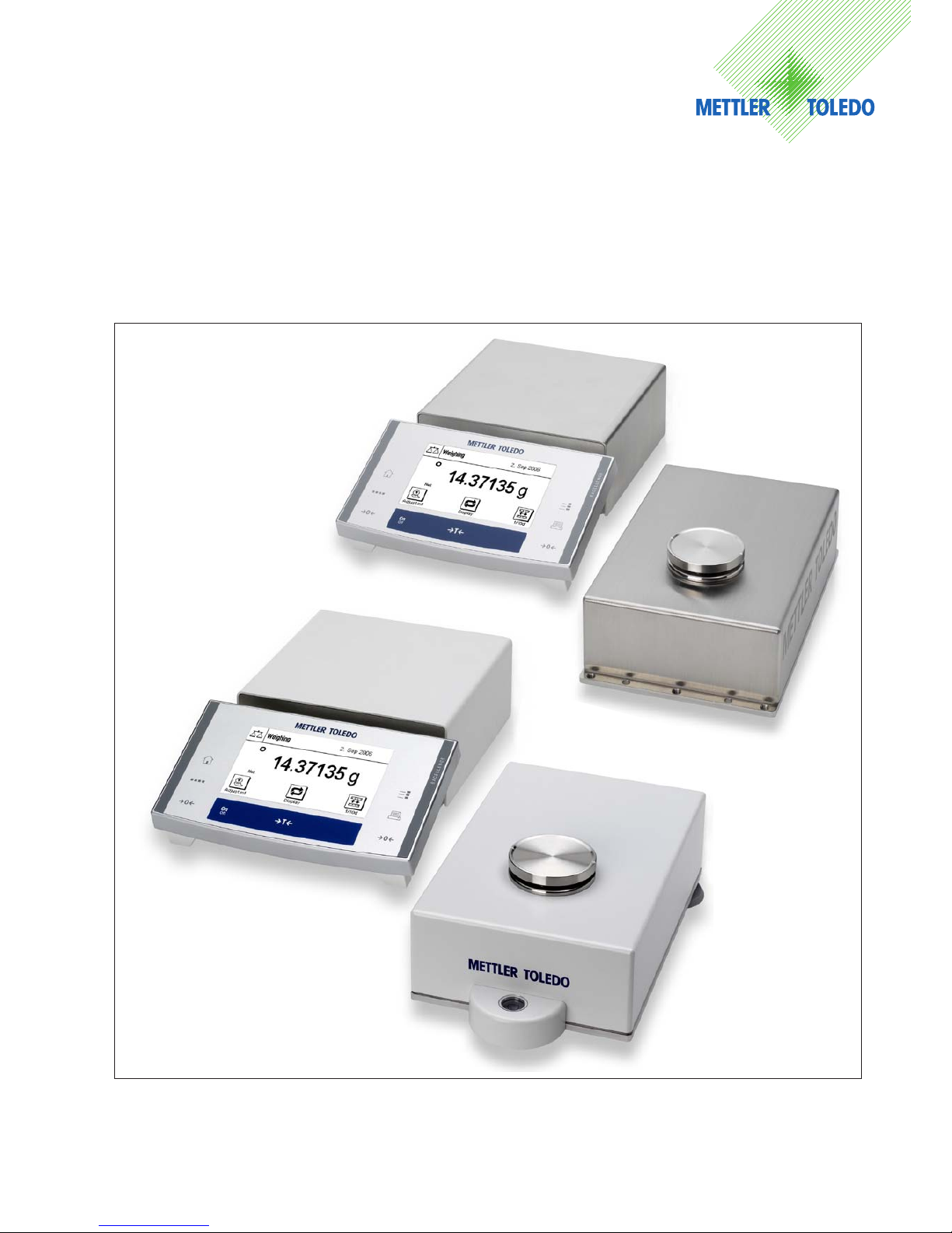
Instructions for Installation and Operation
METTLER TOLEDO
WXS and WXT Weighing Modules
Page 2
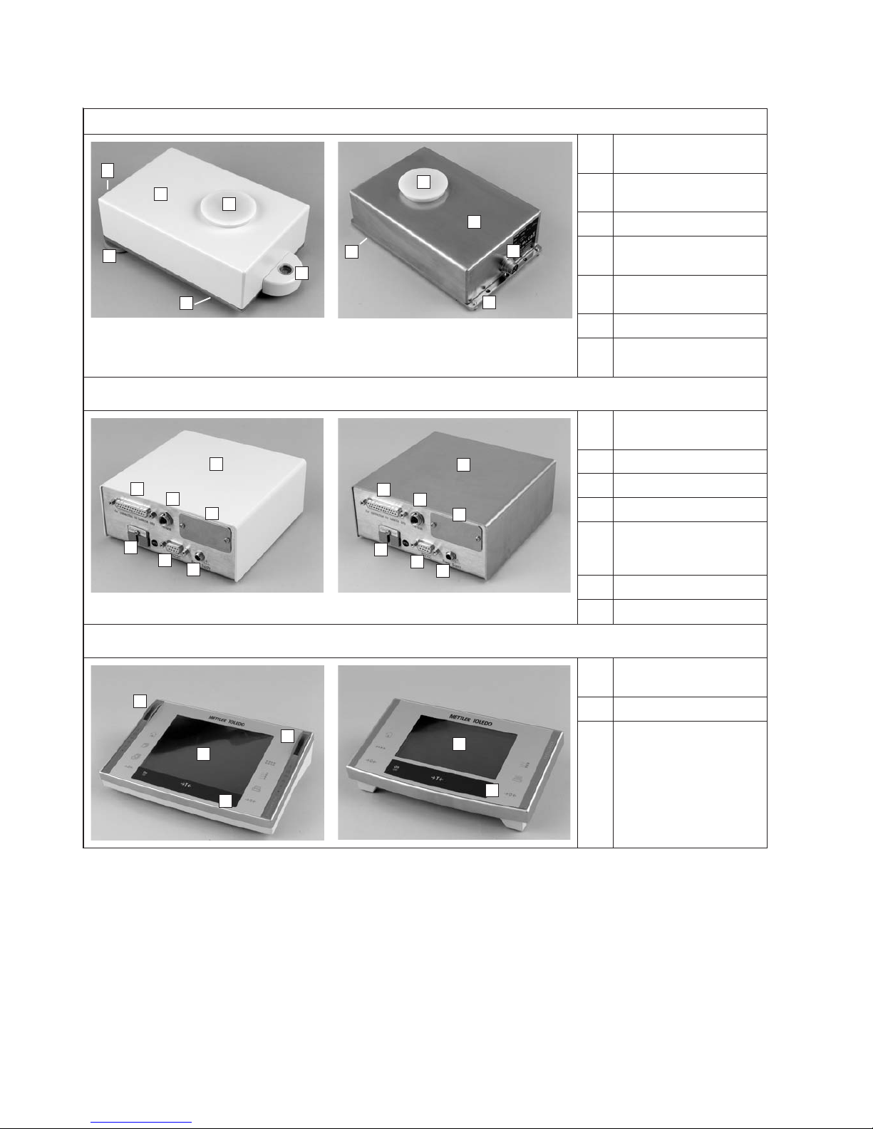
Load Cells
1
3
4
5
6
2
1
2
3
4
7
1 Housing (WXT: white powder-
coated, WXS: stainless steel)
2 Weighing pan retainer
with plastic cover
3 Connector for electronic unit
4 Hanger opening for weighing
below (on bottom side)
5 Level bubble (leveling aid,
on WXT model only)
6 Adjustable feet (WXT only)
7 Base plate with mounting
flange (WXS only)
Electronic units
8
9
10
11
12
13
14
8
9
10
11
12
13
14
8 Housing (WXT: white powder-
coated, WXS: stainless steel)
9 Load cell connector
10 Terminal connector
11 Optional interface plug-in
12 “Aux” connectors (for
“ErgoSens,” hand or footoperated buttons)
13 RS232-C standard interface
14 Connector for AC adapter
Terminals
15
16
17
17
15
16
15 Display (PWT: color,
SWT: monochrome)
16 Keyboard
17 “SmartSens” sensors
(PWT only)
The WXS and WXT weighing modules at a glance
WXT WXS
WXT WXS
PWT SWT
Page 3
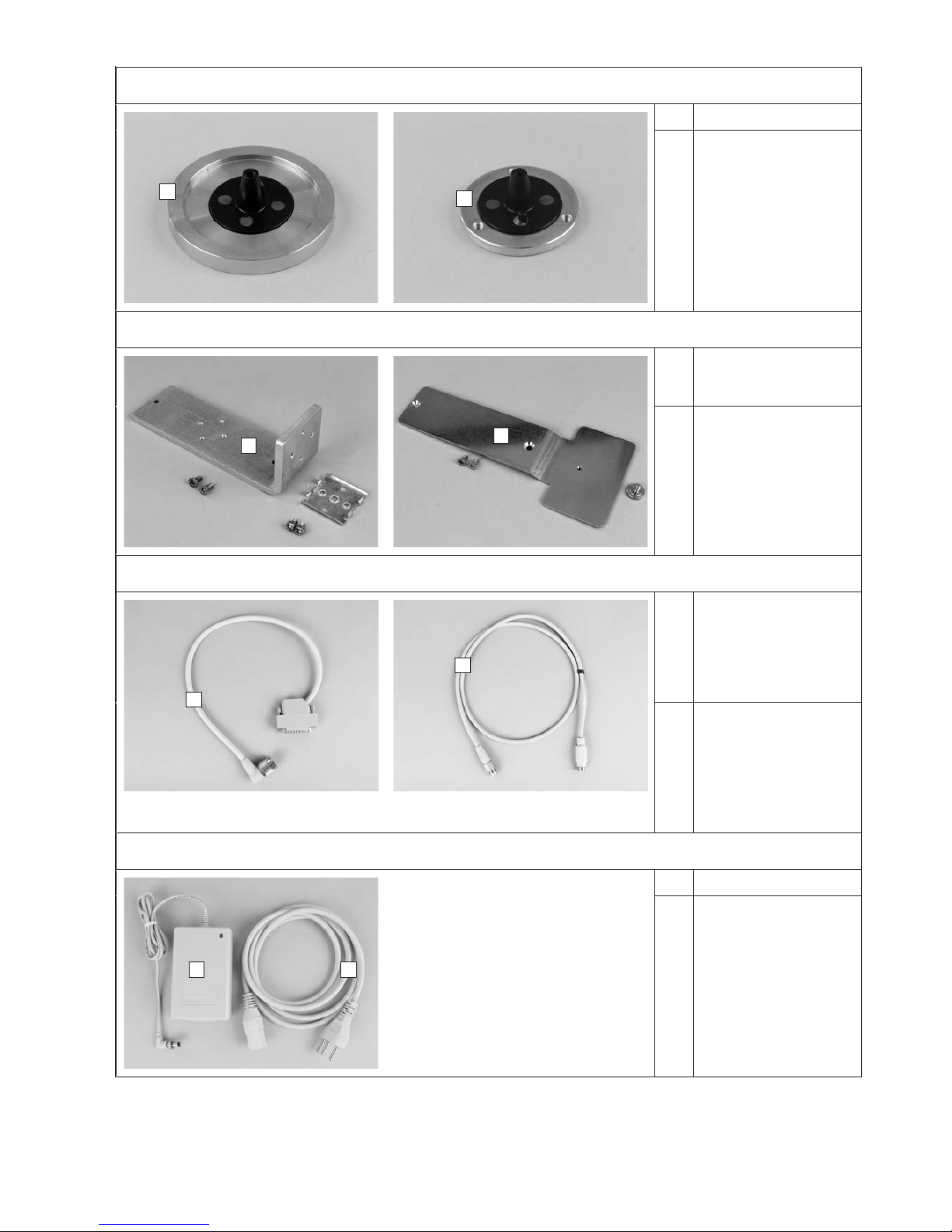
Weighing pans
18
19
18 Standard weighing pan
19 Adapter weighing pan
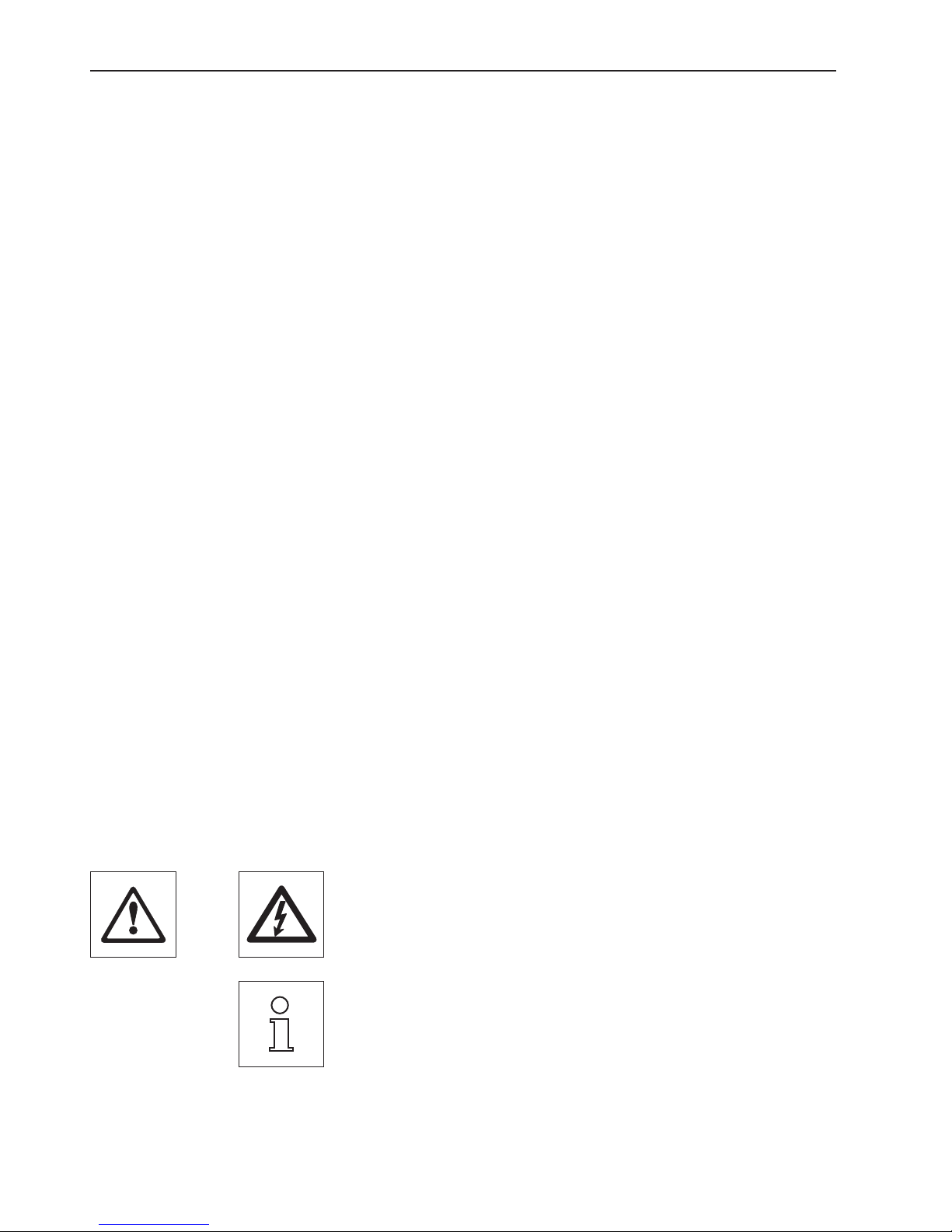
Mounting materials
20
21
20 Mounting bracket for WXS
electronic unit, including
DIN clip and screws
21 Terminal holder for SWT
terminal, including screws
Connecting cables
22
23
22 Electronic unit – load cell
connector cable
(0.5m/1.6ft or
1.5m/5ft long)
Note: The maximum allowable
cable length is 5m/16.4ft.
23 Terminal – electronic
unit connector cable
(0.575m/1.9ft or
2m/6.5ft long)
Note: The maximum allowable
cable length is 5m/16.4ft.
Power supply
24 25
24 AC adapter
25 Power cable (country-
specific)
Page 4

Contents
4
Contents
1 Introduction .................................................................................................................................................... 6
1.1 Introduction to the WXS/WXT weighing modules ............................................................................................................ 6
1.2 What you should know about this manual .....................................................................................................................6
1.3 Safety first! ...................................................................................................................................................................7
1.4 Available documentation ..............................................................................................................................................8
2 Initial startup of weighing modules .................................................................................................................. 9
2.1 Unpacking the weighing module and notes on packaging..............................................................................................9
2.2 Scope of delivery .......................................................................................................................................................10
2.3 Assembling of WXS weighing module .........................................................................................................................11
2.3.1 Load cell installation ..................................................................................................................................................11
2.3.2 Electronic unit assembly and mounting ....................................................................................................................... 12
2.4 Weighing module WXT setup ...................................................................................................................................... 12
2.4.1 Choosing a location ................................................................................................................................................... 12
2.4.2 Levelling the load cell.................................................................................................................................................13
2.5 Place weighing pan....................................................................................................................................................13
2.5.1 Standard weighing pan ..............................................................................................................................................13
2.5.2 Adapter weighing pan ................................................................................................................................................14
2.5.3 Notes on weighing below ...........................................................................................................................................14
2.5.4 Overload protection .................................................................................................................................................... 15
2.6 Connect load cell and electronic unit ..........................................................................................................................16
2.7 Connect terminal and adjust settings .......................................................................................................................... 16
2.7.1 SWT Terminal ............................................................................................................................................................16
2.7.2 PWT Terminal ............................................................................................................................................................17
2.8 Connect the unit to the power supply .......................................................................................................................... 18
3 Configuring the weighing module .................................................................................................................. 19
3.1 Extended SICS command set for WXS/WXT weighing modules without terminal ............................................................21
3.2 Standard SICS command set for WXS/WXT weighing modules without terminal .............................................................21
3.3 Preparatory steps for configuration ..............................................................................................................................24
3.4 Configuring the weighing module ...............................................................................................................................25
3.4.1 Adjusting the weighing module ................................................................................................................................... 25
3.4.2 Set readability ............................................................................................................................................................25
3.4.3 Set stability criteria .....................................................................................................................................................26
3.4.4 Activating and defining the fixed filter .......................................................................................................................... 28
3.4.5 Adjustments to ambient conditions (filter damping) .....................................................................................................29
3.4.6 Setting the update rate for continuous weight transmission ..........................................................................................29
3.4.7 Recording user settings .............................................................................................................................................. 30
3.4.8 Resetting user-specific settings to factory default .........................................................................................................31
3.4.9 Information on the memory location for user-specific settings ...................................................................................... 32
4 Weighing operation ......................................................................................................................................33
4.1 Transmission of weight values ....................................................................................................................................33
4.2 Taring function ........................................................................................................................................................... 34
4.3 Zeroing functions ....................................................................................................................................................... 35
Page 5

Contents
5
4.4 Troubleshooting weighing module errors and malfunctions .........................................................................................36
4.4.1. If your weighing module doesn’t perform correctly until it has been powered up for quite a while .................................. 36
4.4.2 If the weighing module does not transmit the expected weight readings ....................................................................... 36
4.4.3 If the weighing module doesn’t react to your commands at all ..................................................................................... 36
5 Maintenance and Service .............................................................................................................................. 37
5.1 Cleaning the weighing module ...................................................................................................................................37
5.2 Maintenance .............................................................................................................................................................37
6 Technical Data, Accessories, and Replacement Parts ....................................................................................... 38
6.1 General data .............................................................................................................................................................. 38
6.2 Model-specific data ....................................................................................................................................................40
6.3 Key to types and list of available models .....................................................................................................................42
6.4 Dimensions ...............................................................................................................................................................43
6.4.1 WXS load cell dimensional drawing ............................................................................................................................43
6.4.2 WXT load cell dimensional drawing ............................................................................................................................. 44
6.4.3 Adapter weighing pan dimensional drawing ................................................................................................................ 45
6.4.4 WXS electronic unit dimensional drawing (including mounting bracket) ....................................................................... 45
6.4.5 WXT electronic unit dimensional drawing (including terminal holder) ...........................................................................46
6.4.6 SWT terminal dimensional drawing (mounted using terminal holder) ........................................................................... 47
6.4.7 PWT terminal dimensional drawing ............................................................................................................................ 48
6.4.8 Adapter for weighing below (optional), dimensional drawing ........................................................................................49
6.5 RS232C interface (standard interface) specifications ................................................................................................... 50
6.6 Specification for Aux connections ................................................................................................................................ 50
6.7 Accessories and Replacement Parts ............................................................................................................................51
6.7.1 Accessories ...............................................................................................................................................................51
6.7.2 Replacement parts ..................................................................................................................................................... 52
7 Appendix .....................................................................................................................................................53
7.1 Conversion table for weight units ................................................................................................................................ 53
7.2 SOP - Standard Operating Procedure ........................................................................................................................... 54
7.3 Updating firmware ......................................................................................................................................................55
7.4 Glossary ....................................................................................................................................................................55
8 Index ........................................................................................................................................................... 58
Page 6
Introduction
6
1 Introduction
Thank you for choosing a METTLER TOLEDO weighing module.
This section will provide you with basic information on the WXS and WXT weighing modules. Even if you have previous experience with
other scales or METTLER TOLEDO scales, please read this section carefully. It is VERY IMPORTANT that you obey all safety instructions!
1.1 Introduction to the WXS/WXT weighing modules
These instructions apply to all WXS and WXT weighing modules. The models differ in their weighing ranges, resolution, mechanical
structure, features, and the included accessories. The text makes a special point of mentioning items that have an impact on operating
the unit.
The weighing modules are available in two different versions: a benchtop version (WXT) and a component version (WXS).
Each weighing module consists of a load cell, an electronic unit and a terminal (optional). The load cell and electronic unit are avail-
able in either a benchtop or component version. There are two terminals available that can be used with both the benchtop and the
component versions. The smaller SWT terminal has a monochrome display and built-in applications. The large PWT terminal has a
color display, supports multiple user profiles and also has an added “MinWeigh” application. There are separate instruction manuals
available for the terminals.
All WXS/WXT models have the following features:
– “Fact” adjustment and linearization with two internal weights
– Integrated RS232C interface
– Optional interface plug-in
– Standard weighing pan and additional adapter weighing pan provided for users to create their own setups
– Plastic cover provided for cleaning the weighing module and establishing ingress protection of IP65
– A full set of cables and mounting accessories is provided
– A CD-ROM with additional instructions and a PC program for setup and operation of the weighing module are also included
A brief word regarding standards, directives and procedures for quality assurance: The WXS and WXT weighing modules comply with all
commonly accepted standards and guidelines. They support standard processes, requirements and work methodologies in accordance
with GLP (Good Laboratory Practice) and GMP (Good Manufacturing Practice) and allow for the creation of SOPs (Standard Operating
Procedures). The WXS/WXT weighing modules have been issued a CE-Declaration of Conformity. METTLER TOLEDO, the manufacturer,
is both ISO 9001 and ISO 14001certified.
1.2 What you should know about this manual
The following conventions apply to the entire manual:
These symbols mark safety and hazard warnings. Failure to comply with these warnings
may result in personal risk to the user, damage to the weighing module or other property,
or unit malfunction.
This symbol marks additional information and notes. Following these instructions will
make it easier for you to work with the weighing module and ensure proper and efficient
use of the unit.
Page 7
Introduction
7
These symbols mark specific information on setting up, configuring, or operating weighing
modules without a terminal (“–T”) or with a terminal (“+T”).
+T–T
1.3 Safety first!
Please follow the tips and instructions given below on the safe operation of your WXS/WXT weighing module. Always operate and
use your weighing module solely in accordance with the instructions given in this manual. Failure to do so may limit the protection
the unit can offer you. Be sure to follow the instructions on the initial startup of your new weighing module.
WXS/WXT weighing modules may be used only in closed indoor spaces. Never operate
these units in areas where there is any explosion hazard.
METTLER TOLEDO recommends that you use the AC adapter provided with your unit to
operate it. Make sure that the voltage printed on the adapter matches your local power
supply. Plug the adapter into a grounded outlet only.
Your WXS/WXT weighing module is built to be tough, but it is still a precision instrument.
Handle it carefully.
Do not open the weighing module. There are no user-servicable parts inside. If you should
ever have a problem with your weighing module, please contact the METTLER TOLEDO
office nearest you.
Use only METTLER TOLEDO accessories and peripheral devices with your weighing module;
these items are designed to work optimally with your WXS/WXT weighing module.
Disposal
In compliance with the requirements of the EU Waste Electrical and Electronic Equipment
Directive 2002/96/EU (WEEE), this unit may not be disposed of with household waste.
The spirit of this Directive also applies to countries outside the EU in accordance with
currently valid national regulations.
Please dispose of this product in compliance with local regulations in a separate collection
for electrical and electronic equipment.
If you have any questions, please contact the responsible authority or the dealer from
whom you purchased your unit.
If you sell or give your unit to someone else (e.g., for private or commercial/industrial use),
this stipulation must be made known to the new owner as appropriate.
Thank you for helping protect the environment.
Page 8
Introduction
8
1.4 Available documentation
The table below lists all documentation available for the WXS and WXT weighing modules, along with the document numbers for each
document.
German English French Spanish Italian
Instructions for Installation and
Operation of the WXS and WXT
weighing modules (this document)
11780991 11780992 – – –
MT-SICS reference manual – 11780711 – – –
Instructions for SWT terminal
(XS scale instruction manual, Part 2)
11781117 11781118 11781119 11781120 11781121
Instructions for PWT terminal
(XP scale instruction manual, Part 2)
11781076 11781077 11781078 11781079 11781080
The CD-ROM (11781008) provided with your unit includes all of the documents listed above. Also, printed copies of all instructions are
provided in the language of the country to which the unit is delivered. Printed instructions for SWT or PWT terminals are included only
for weighing modules with terminals.
Page 9
Initial startup of weighing modules
9
2 Initial startup of weighing modules
This section tells you how to unpack your new weighing module, set it up, and prepare it for operation.
2.1 Unpacking the weighing module and notes on packaging
The load cell, the electronic unit, and the terminal are each packed in separate cardboard boxes along with the associated hardware
and appropriate mounting materials. The boxes are labeled with their contents as follows: “Weighing Module,” “Electronic Unit,” and
“Terminal”.
Depending on whether you’ve ordered a weighing module with or without a terminal, you will receive either 2 or 3 boxes that are placed
inside a large transport box.
Unpacking the electronic unit and terminal:
Remove the top foam cushion and remove the electronic unit and the hardware.
Unpacking the load cell:
Remove the black foam cushion and take out the hardware.
Carefully lift the white cushion containing the load cell out of the box and place it on a
level surface.
Carefully pull the white cushioning material a few inches apart and remove the load
cell.
Keep all packaging in case you need to ship the module in the future; the weighing
module should only be transported in its original packaging.
Page 10
Initial startup of weighing modules
10
2.2 Scope of delivery
The scope of delivery for your weighing module depends on the specific model that you ordered. Please check the scope of delivery
using the following table. If any parts are missing or defective, please report this to your METTLER TOLEDO representative or the shipper
immediately.
WXS204/15
WXS205DU/15
WXS204V/15
WXS205DUV/15
WXSS204
WXSS205DU
WXSS204V
WXSS205DUV
WXTS204
WXTS205DU
WXTS204V
WXTS205DUV
WXTP204
WXTP205DU
WXTP204V
WXTP205DUV
“Weighing Module” Box
WXS load cell (component version) with
attached plastic cover to cover the weighing
pan retainer.
WXT load cell (benchtop version) with attached plastic cover to cover the weighing
pan retainer.
Standard weighing pan
Adapter weighing pan
WXS/WXT weighing module instructions
(this document)
Production certificate and CE Declaration of
Conformity
CD-ROM with instructions and PC software
“Electronic Unit” Box
WXS electronic unit (component version)
WXT electronic unit (benchtop version)
Electronic unit-load cell connector cable,
0.5m/1.6ft long
Electronic unit-load cell connector cable,
1.5m/5ft long
Mounting bracket for electronic unit,
including clip and screws for attaching
to DIN standardized rail
Terminal holder, including screws (for
attaching the terminal to the electronic unit)
AC adapter
Power cable (country-specific)
MT-SICS reference manual
“Terminal” Box
SWT terminal (monochrome display),
including protective covering
PWT terminal (color display), including
protective covering
Terminal-electronic unit connector cable,
0.575m/1.9ft long
Terminal-electronic unit connector cable,
2m/6.5ft long
Terminal instruction manual
(XS/XP instructions, Part 2)
Page 11
Initial startup of weighing modules
11
2.3 Assembling of WXS weighing module
The WXS (component version) weighing modules can be integrated into higher-level systems (machines, systems, etc.). Be sure to
follow the tips in the following sections to select the optimal installation method
2.3.1 Load cell installation
The weighing modules were designed to record weights very quickly and accurately under normal conditions and communicate the
result using the integrated interface and/or display the result on a terminal. In practice, ambient conditions (vibration, oscillations, shocks,
air movements and temperature changes) affect weighing time and achievable accuracy as well as the repeatability.
You can adjust various parameters on your weighing module (Section 3). We recommend that you adjust the settings to the levels
needed for your application; higher requirements increase the weighing time (period between the placement of the weight and the
availability of a stable result).
Filter settings must be stricter to compensate for unfavorable ambient conditions (Section 3); this also has a negative impact on weigh-
ing time. Therefore, be sure to note the following:
– Mount the load cell on a base that is mechanically decoupled from the system and therefore free of shocks and vibration. If a
mechanical decoupling is not possible, place appropriate cushioning between the system and the load cell mount.
– The location of the load cell should not be in areas that are exposed to drafts, direct
sunlight, or severe temperature fluctuations.
– Make sure that any vibrations in the building are not transferred through the floor and
to the load cell
– Make sure that the load cell is as perfectly horizontal as possible. Use a precision level
to achieve exact leveling. It is acceptable to have a unit that is not perfectly horizontal
if its position is not altered after it has been adjusted (e.g., if it is mounted in a fixed
position in the system).
– Attach the load cell to the base across as wide an area as possible. Use the appropri-
ate bores in the front part of the cell’s base plate (4x M5 screws, tightening torque
4 – 6Nm). The base must be perfectly planar to avoid putting tension on the load cell
base plate.
– Make sure that vibrations cannot be transferred across the connector cable between
the load cell and the electronic unit.
– Make sure that the load cell housing is connected in an electrically conductive manner
with the machine structure.
If your requirements are extremely demanding (short weighing time, high accuracy),
we recommend that you try a test setup first and test the entire system under real-world
conditions using various settings (Section 3). This will allow you to tweak the system and
optimize it bit by bit.
Page 12
Initial startup of weighing modules
12
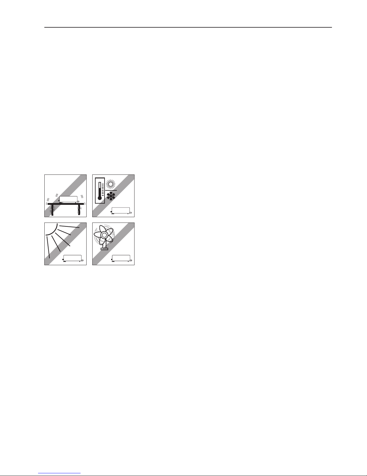
Pick a location that is stable, vibration-free and shock-free, and as horizontal as possible.
The floor beneath the weighing module must be able to safely hold the weighing module
with the maximum possible load on the load cell.
Take care to ensure the proper ambient conditions (Section 6).
Avoid:
– Direct sunlight
– Strong drafts (e.g. from fans or climate-control systems)
– Extreme temperature fluctuations.
2.4 Weighing module WXT setup
The WXT weighing module (benchtop version) does not require any assembly work. Note the information in the following sections about
choosing an optimal location and leveling the load cell.
2.4.1 Choosing a location
Your weighing module is a precision instrument. Provided with an optimal location, it will reward you with great accuracy and
reliability.
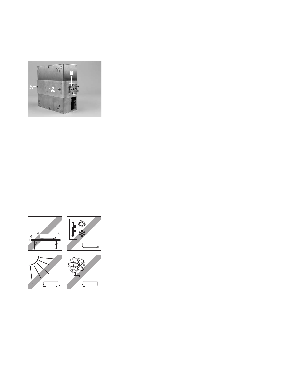
Remove the two existing screws from the bottom side of the electronic unit (Torx T-20)
and use the provided Torx T-20 countersunk head screws (A) to secure the mounting
bracket.
Secure the clip (B) to the front face or underside of the mounting bracket. Use the two
provided M4 pan head screws (Torx T-20) to do so.
Note: The electronic unit can also be attached directly to the mounting bracket (without
a clip) via the M4 thread using a support.
Important: The electronic unit meets the requirements for protection class IP40. If required,
appropriate protective measures must be taken to protect the unit from dirt.
Additional assembly items:
– Place weighing pan (Section 2.5)
– Connect load cell and electronic unit (Section 2.6)
– Connect terminal and adjust settings (Section 2.7)
– Connect the unit to the power supply (Section 2.8)
A
B
A
2.3.2 Electronic unit assembly and mounting
The electronic unit can be mounted in any position you wish. A mounting bracket and clip for attaching the unit to a DIN standardized
rail are provided. Proceed as follows for mounting:
Page 13
Initial startup of weighing modules
13
2.4.2 Levelling the load cell
Once the load cell has been set up at the desired location, the load cell must be horizontally aligned (leveled).
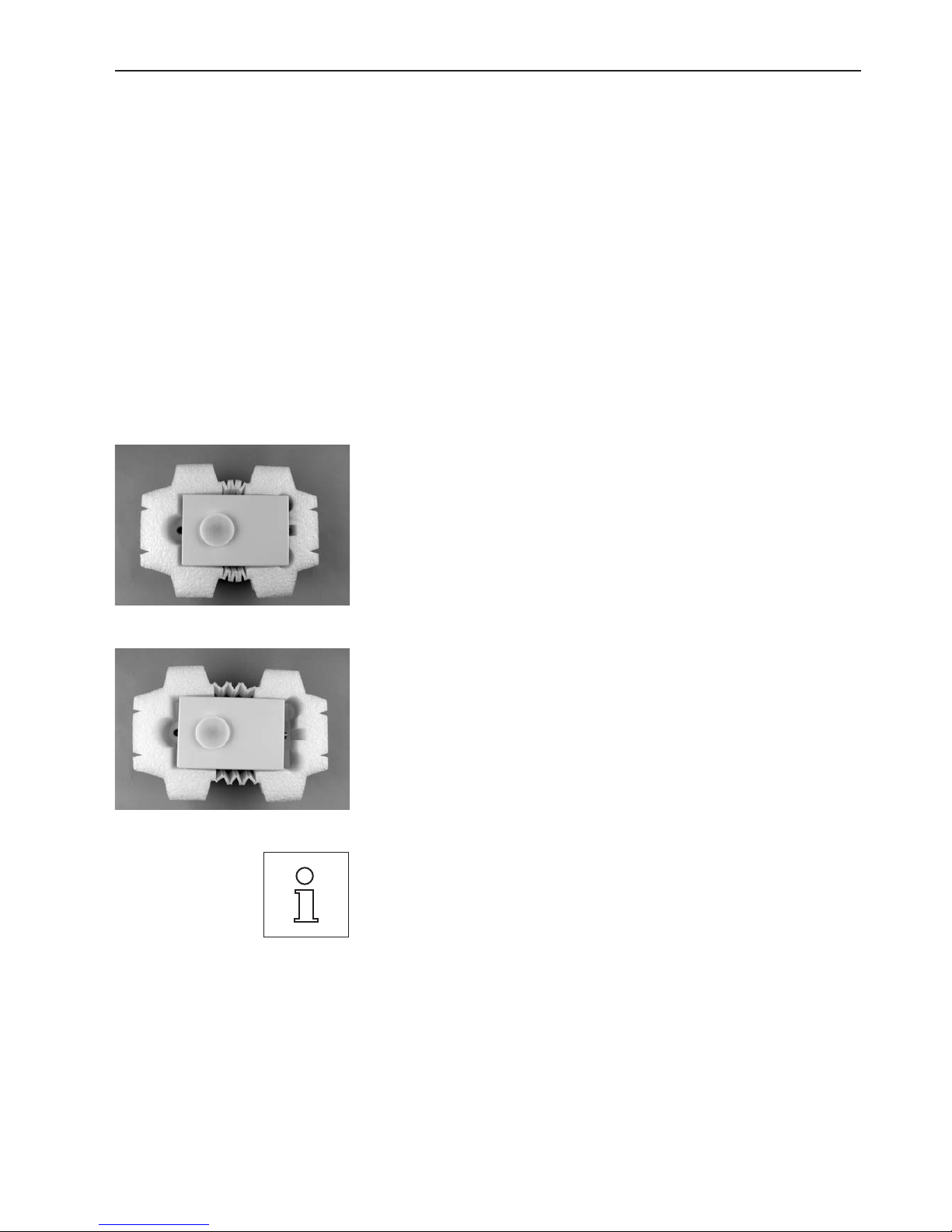
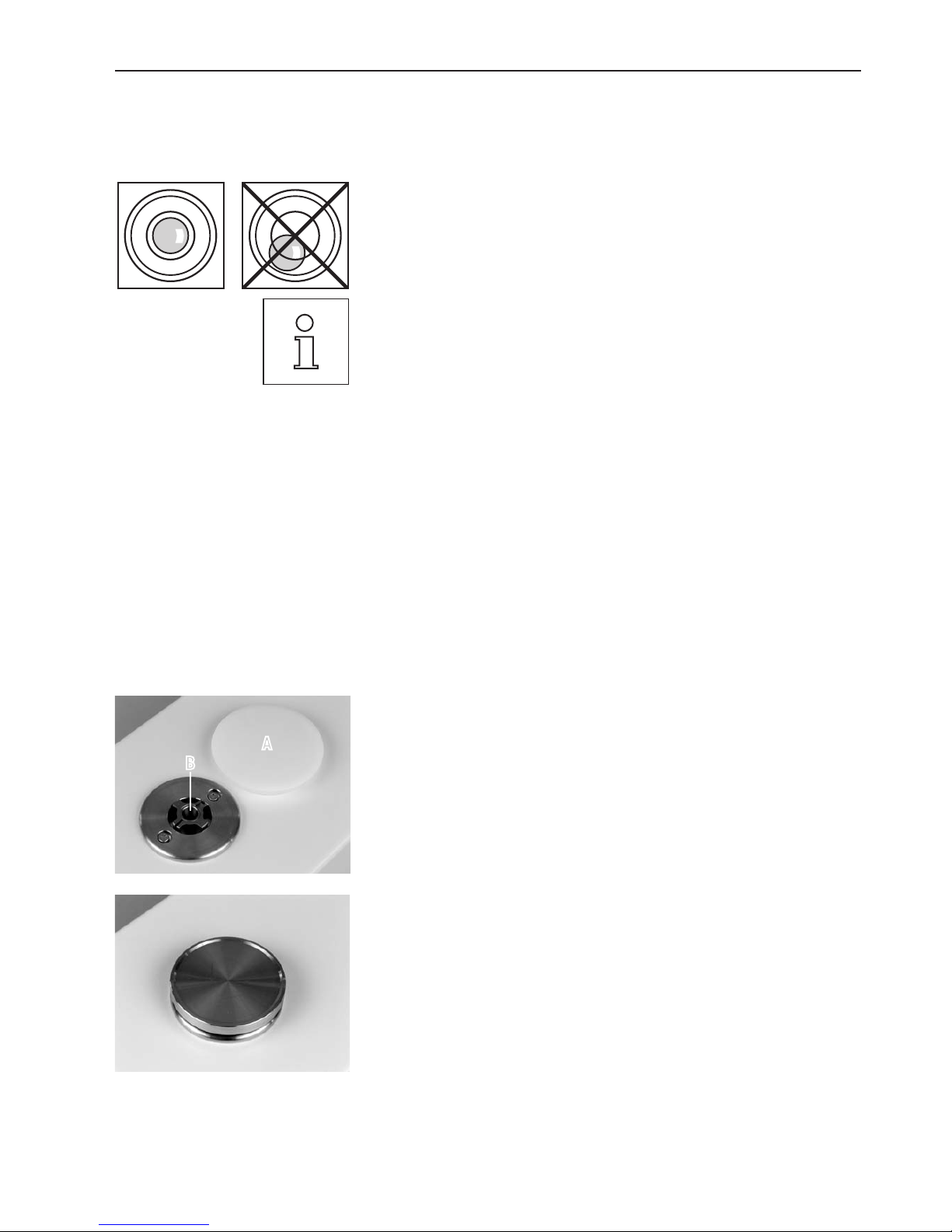
The load cell is equipped with a level (level bubble) and two adjustable feet. The load cell
is completely horizontal when the bubble is precisely in the middle of the level window
(left image = properly level, right image = not properly level).
Adjust both feet as necessary until the air bubble is right in the middle of the level
window.
Note:You should always level the load cell after moving it to a new location.
Additional tasks:
– Place weighing pan (Section 2.5)
– Connect load cell and electronic unit (Section 2.6)
– Connect terminal and adjust settings (Section 2.7)
– Connect the unit to the power supply (Section 2.8)
2.5 Place weighing pan
The WXS and WXT weighing modules come with two weighing pans: a standard weighing pan and an adapter weighing pan for users
to create their own setups.
2.5.1 Standard weighing pan
Remove the white plastic cover (A) from the load cell. This cover protects the weighing
pan retainer (B) from damage during transport and keeps liquid out of the load cell during
cleaning. Make sure you keep the cover in a safe place!
Place the weighing pan cone into the weighing pan retainer. You do not need to insert it
in any specific position; the standard weighing pan will turn freely.
A
B
Page 14
Initial startup of weighing modules
14
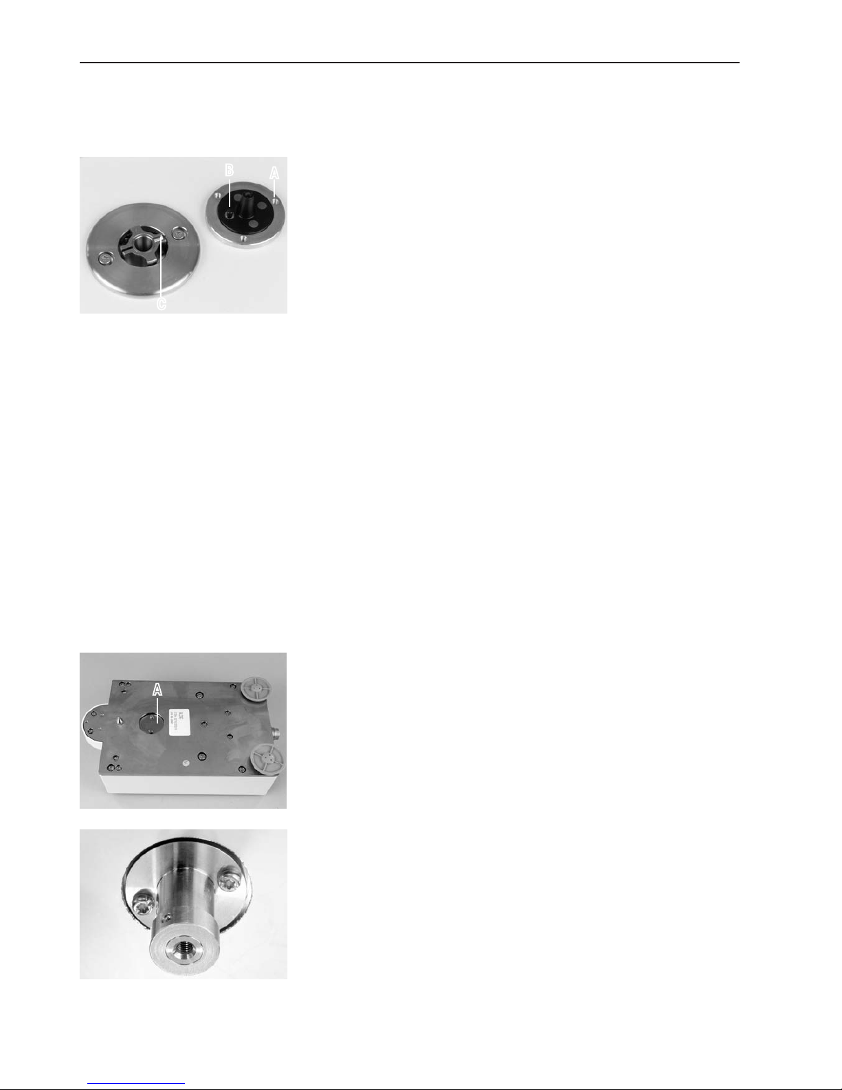
2.5.2 Adapter weighing pan
The adapter weighing pan is used for customer-specific setups to hold the object to be weighed.
The customer-specific setup can be attached to the weighing pan using the three 120°
offset M3 threaded holes (A). See Section 6 for the exact dimensions of the adapter
weighing pan.
Keep in mind that your setup must weigh at least 55 g to ensure that the required dead
load of 65 g (weighing pan + setup) is reached. If the required dead load is not reached,
the weighing module will output an underload error message upon startup.
To preserve the full weighing range, the total preload (weighing pan + setup) may not
exceed 88 g. Heavier preloads will take away from the available weighing range.
Because customer-specific setups generally remain in a fixed position, the adapter weighing
pan has a positioning pin (B). This pin fits perfectly in the wider of the two grooves in the
weighing pan retainer (C) and prevents the weighing pan from turning freely. However, this
anti-displacement measure works only up to a certain torque. If this torque is exceeded,
the weighing pan and weighing pan retainer turn together to prevent damage to the load
cell. At the same time, the weighing pan retainer serves a protection from lateral forces.
B
C
A
2.5.3 Notes on weighing below
For weighing beneath the work area (weighing below), the load cell is equipped with a hanger opening. For weighing below, the item
to be weighed is not placed on the weighing pan; it is placed on an application-specific receptacle attached beneath the load cell. For
weighing below, the standard weighing pan is removed, and the weighing pan retainer is closed up using the plastic cover so that dirt
and foreign matter cannot penetrate the load cell.
Here are some examples of when weighing below is used:
– when it is difficult or impossible to put the material to be weighed on the weighing pan
– when space will not allow for items to be weighed from above
– when weighing from above might soil or contaminate the load cell.
The hanger opening is on the bottom of the cell under a round cover (A).
You’ll need the optional weighing below adapter, which should be installed by a
METTLER TOLEDO service technician if possible, to attach the customer-specific receptacle
(see Section 6 for information on how to order).
A
Page 15
Initial startup of weighing modules
15
Please keep the following in mind when planning a weighing below receptable for objects
to be weighed:
– The fixture must weigh at least 52 g, to ensure that the required dead load of 65 g
(weighing below adapter + fixture). If the required dead load is not reached, the weighing
module will output an underload error message upon startup. To preserve the full weighing range, the total weight of the weighing below adapter and fixture may not exceed
88 g. Heavier preloads will take away from the available weighing range.
– Secure the fixture to the M4 thread of the weighing below adapter (max. penetration
depth: 8mm, max. tightening torque: 1 Nm, see also dimensional drawing in Section
6.4.8).
– Position the fixture’s center of gravity as close to and vertically beneath the attachment
point as possible.
– The weighing receptacle must hang freely from the attachment point of the weighing
below adapter without touching non-moving parts of the load cell or the system. The
maximum diameter or cross-section of the fixture at the attachment point is 8 mm.
– Limit the vertical and horizontal movement and/or torsion of the fixture by using me-
chanical stops to prevent overload of the load cell.
– To minimize weighing time, avoid vibrations and shocks to the fixtures and the objects
to be weighed.
2.5.4 Overload protection
The WXS/WXT weighing modules have overload protection that is effective in all directions up to the following limit values:
Vertical load: 5 kg (all types; centered load)
Lateral load: 1 kg (protected by torsion protection; see Section 2.5.2)
Torsion: Protected by torsion protection (see Section 2.5.2)
Page 16
Initial startup of weighing modules
16
2.6 Connect load cell and electronic unit
Use the provided cable (0.5 m or 1.5 m long) to connect the load cell to the electronic
unit (a 5 m cable is available as an accessory).
Tighten the plugs on both devices.
Note: The load cell and the electronic unit can be replaced independently of each other
if necessary.
Lay the cable so that no one will trip over it and so that no vibration can travel up the
cable and be transferred to the load cell.
2.7 Connect terminal and adjust settings
You’ll need this section only if your weighing module was delivered with a terminal.
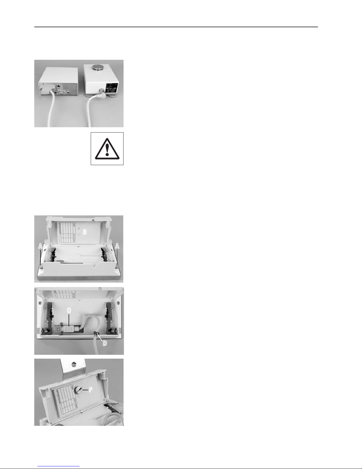
2.7.1 SWT Terminal
Place the terminal on a flat surface with the display face down.
Press the two tabs (A) on the back of the terminal to open it, and open the bottom of the
terminal (B).
Feed the terminal cable through the cutout in the back of the terminal and plug in the
jack (C). Make sure that the strain relief (D) is inside the terminal.
If you want to permanently affix the terminal to the electronic unit, you can also attach
the terminal holder now:
Place the terminal holder (E) into the corresponding cutout on the bottom of the terminal
and use the knurled screw (F) provided to secure it from the inside of the terminal.
A A
B
D
C
E
F
Page 17
Initial startup of weighing modules
17
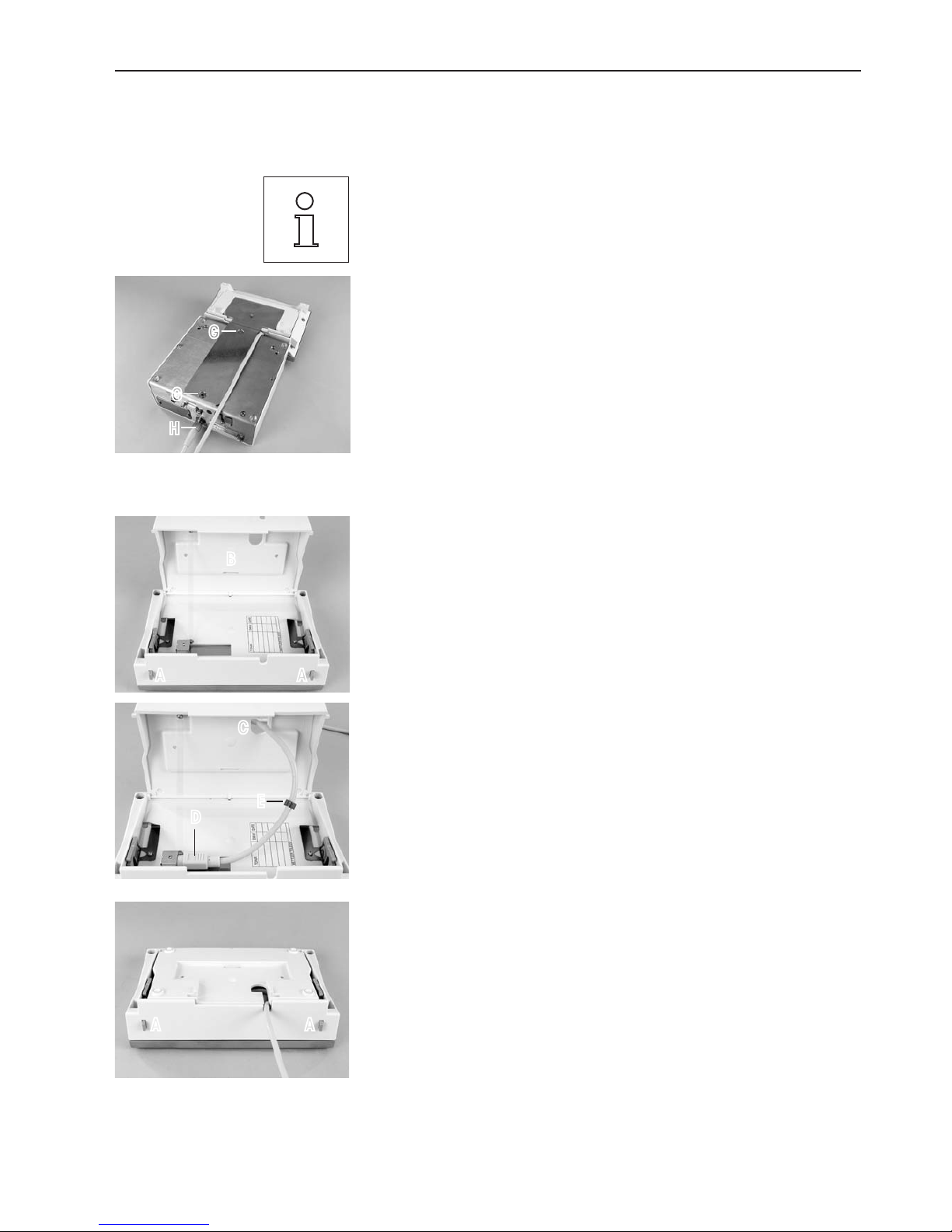
Close the bottom of the terminal. Then push in the two side tabs to completely close the
terminal.
Note: You can also use the two tabs on the back side to adjust the viewing angle of the
terminal while it is in operation: Press both buttons simultaneously and pull the top of
the terminal gently upwards, or press it down until it clicks into the desired position. You
can choose from three different positions.
Remove the two screws (Torx T-20) in the bottom of the electronic unit and store them in
a safe place. Align the terminal holder exactly with the two bores and secure it with the
Torx T-20 countersunk head screws (G).
Plug the terminal cable plug (H) into the appropriate jack on the back of the electronic
unit and screw in to tighten. Try to run the terminal cable as close as parallel as possible
to the terminal holder.
G
G
H
2.7.2 PWT Terminal
Place the terminal on a flat surface with the display face down.
Press the two tabs (A) on the back of the terminal to open it, and open the bottom of the
terminal (B).
Feed the terminal cable through the cutout (C) in the bottom of the terminal and plug in
the jack (D). Make sure that the strain relief (E) is inside the terminal.
Close the bottom of the terminal. Then press the two tabs (A) on the back of the terminal
to completely close the terminal.
Note: You can also use the two tabs on the back side to adjust the viewing angle of the
terminal while it is in operation: Press both tabs simultaneously and pull the top of the
terminal gently upwards, or press it down until it clicks into the desired position. You can
choose from three different positions.
Plug the terminal plug into the appropriate jack on the back of the electronic unit and
screw in to tighten.
A A
B
C
D
E
A A
Page 18
Initial startup of weighing modules
18
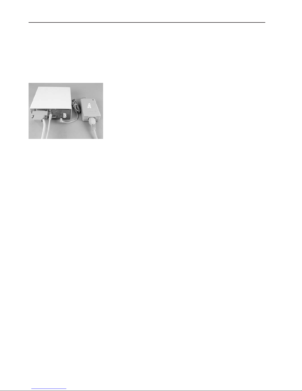
2.8 Connect the unit to the power supply
The electronic unit for your weighing module is delivered with an AC adapter and a power cord for your country. The AC adapter is suit-
able for use with the following voltage range:
100 – 240 VAC, 50/60Hz (see Section 6 for exact specifications).
Check whether your local power supply falls within this range. If it does not, DO NOT connect the electronic unit or the AC adapter
to your power supply and contact your local METTLER TOLEDO office.
Connect the AC adapter (A) to the connector (B) on the back of the electronic unit and to
your power supply. Tighten the connector to ensure a good connection to the electronic
unit.
Important: Be sure to lay the cables so that they cannot be damaged or get in your
way while you’re working! Remember that the AC adapter may NOT come into contact
with any liquids!
Once the weighing module has been connected to the power supply, the weighing module
will perform a self-test, and then it will be ready to operate.
B
A
Page 19

Configuring the weighing module
19
3 Configuring the weighing module
Once the weighing modules have been installed, they must be configured, i.e., prepared for operation. For weighing modules with
terminals, nearly all configuration work can be performed via the terminal; weighing modules without a terminal are configured using
MT-SICS commands issued from a host computer. An expansion of the MT-SICS command set is available for product-specific configu-
ration work.
All weighing modules come from the factory with a built-in RS232C interface. In addition, the modules can be equipped with a second
optional interface (Section 6) that is inserted into the electronic unit. The optional interfaces are delivered with their own instructions
describing installation and all configuration work needed.
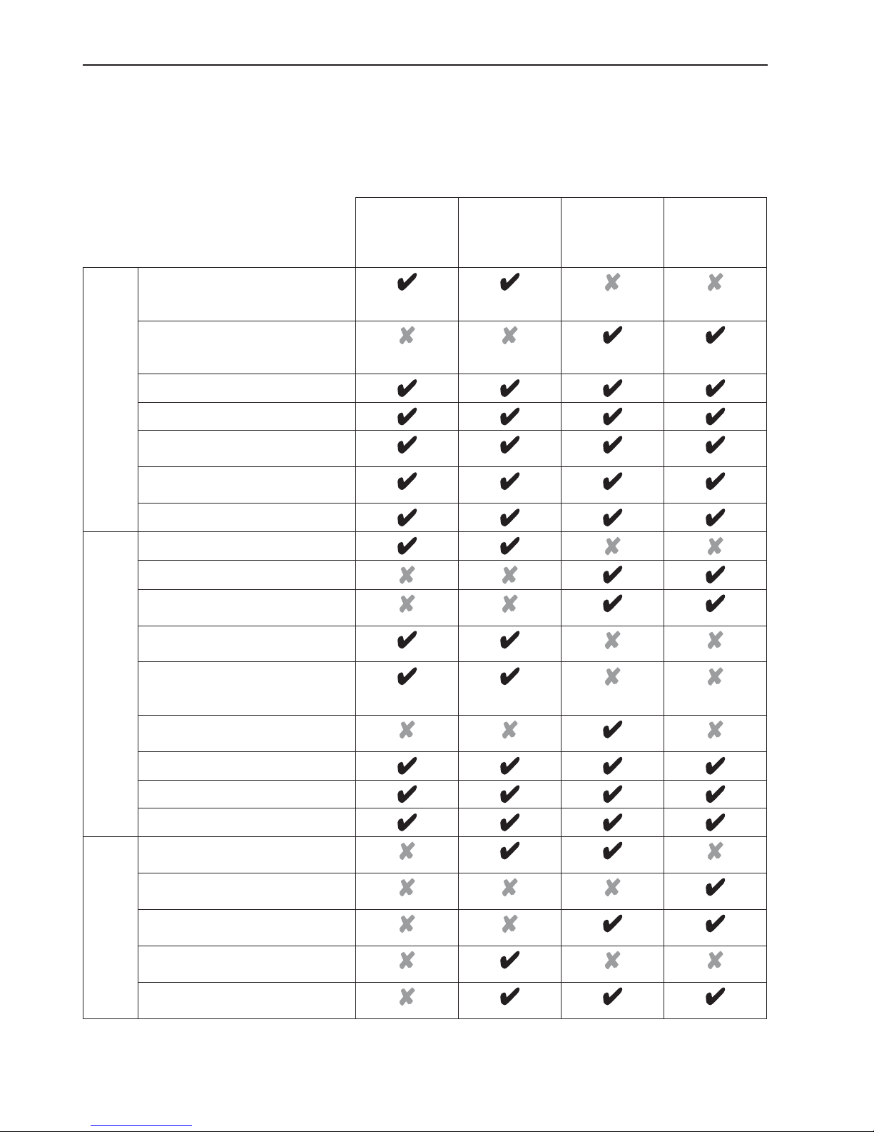
The procedure for configuring the weighing modules and interface functionality depend on how the individual weighing module
is equipped. There are four possible configurations:
1 Weighing module without terminal, with built-in RS232C standard interface
2 Weighing module without terminal, with built-in RS232C standard interface and additional optional interface
3 Weighing module with terminal and built-in RS232C standard interface
4 Weighing module with terminal, built-in RS232C standard interface, and additional optional interface.
The following page provides an overview of the various configurations and the available settings.
Page 20

Configuring the weighing module
20
Configuration
Interface/commands
1 2 3 4
HOST interface Built-in RS232C Optional interface (the built-in
RS232C can be used during
operation to connect a printer,
for example).
Built-in RS232C (can be configured via the terminal for “host”,
see Terminal instructions)
Choice of built-in RS232C or
optional interface (the terminal
can be used to configure one of
the interfaces for the “host,” see
terminal instructions).
Setting interface parameters via MT-SICS “COM” command Host interface: Configured
using SICS command “COPT”
via the built-in RS232C (if
present—otherwise, a terminal
can be hooked up and used to
configure the interface).
Built-in RS232C: Not configurable; will always work with
the factory settings..
Via terminal (as per terminal
instructions)
Via terminal (as per terminal
instructions)
Extended SICS Level 3 instruction set for the HOST
interface
Commands as in Section 3.1.
Note: All SICS commands in
the list in Section 3.2 are also
supported.
Commands as in Section 3.1.
Note: All SICS commands in
the list in Section 3.2 are also
supported.
Not available Not available
Expanded SICS Level 3 commands for second interface
––– Commands as in Section 3.1.
Note: All SICS commands in
the list in Section 3.2 are also
supported (including the “COPT”
command to configure the
“Host” interface) EXCEPT “SIR,”
“SR,” and “SNR”..
––– Not available
“FastHost” commands (as per
MT-SICS reference manual)
Available on host interface Available on host interface Available on built-in RS232C,
assuming it is configured as
host interface
Available on built-in RS232C,
assuming it is configured as
host interface
Notes When the terminal is removed,
the system behaves like a
weighing module without a
terminal, with a RS232C standard
interface (Configuration 1)
When the terminal is removed,
the system behaves like a
weighing module without a
terminal, with a RS232C standard
interface and additional optional
interface (Configuration 2)
Page 21

Configuring the weighing module
21
3.1 Extended SICS command set for WXS/WXT weighing modules without terminal
The following commands were added to the MT-SICS Level 3 command set specifically for the configuration of WXS/WXT weighing
modules:
Command Meaning
FCUT Set filter characteristics (limit frequency)
RDB Set readability
USTB Set stability criteria
FSET Restore factory settings
LST List user settings
3.2 Standard SICS command set for WXS/WXT weighing modules without terminal
The following list provides an overview of the commands from the standard SICS command set that WXS/WXT weighing modules with-
out terminals support. For more detailed information on the individual commands and their parameters, refer to the MT-SICS manual
provided with your system:
Command Meaning
SICS Level 0
I0 Lists all commands supported by SICS levels 0-3
I1 Lists supported MT-SICS level and MT-SICS versions
I2 Inquiry of weighing module data
I3 Inquiry ofSW version and type definition number
I4 Inquiry ofserial number
I5 Inquiry of software verification number
S Send stable net weight
SI Send current net weight without regard for stability
SIR Send continuous current net weight without regard for stability. Note: This command is not available in the built-in
RS232C standard interface on weighing modules without a terminal and with the optional interface.
Z Zero
ZI Zero without waiting for stability
@ Cancel current commands and send serial number to host
SICS Level 1
SR Send stable weight when weight changes (repeatedly). Note: This command is not available in the built-in RS232C
standard interface on weighing modules without a terminal and with the optional interface.
T Trigger taring
TA Inquire and set tare memory
TAC Clear tare memory
TI Trigger taring without waiting for stability. Note: Only permitted on non-calibrated modules.
SICS Level 2
C0 Inquiry/setting of adjustment status Note: Only possible when adjustment is permitted.
C1 Adjust using current configuration. Note: Only possible when adjustment is permitted.
C2 Adjust using external weight. Note: Only possible when external adjustment is permitted.
C3 Adjust using internal weight. Note: Only possible when internal adjustment is permitted.
Page 22

Configuring the weighing module
22
Command Meaning
COM Configuration command for built-in RS232C standard interface. Note: This command is only available for weighing
modules without a terminal and without the optional interface.
COPT Configuration command for optional interface. Note: This command is only available for weighing modules without
a terminal and with the optional interface. The command is only available via the built-in RS232C standard
interface.
DAT Inquiry/setting of date
I10 Inquiry/setting of weighing module ID
I11 Inquiry/setting of module type
I14 Inquiry of information on the weighing module
I15
1)
Inquire duration of operation of the weighing module in minutes since startup
I16
1)
Inquiry of next service date
I21
1)
Inquiry of assortment tolerance dataset version
I22
1)
Inquiry of linearity tolerance
I23
1)
Inquiry of repeatability tolerance
I24
1)
Inquiry of sensitivity tolerance
I25
1)
Inquiry of shift tolerance
I26
1)
Inquiry of operating mode
M01 Inquiry/setting of weighing mode (filter characteristics)
M02 Inquiry/setting of ambient parameters (filter damping)
M03 Inquiry and activation/deactivitation of AutoZero (automatic zeroing)
M17 Inquiry/setting of FACT time criterion. Note: Only possible when time-controlled FACT adjustment is permitted.
M18 Inquiry/setting of FACT temperature criterion. Note: Only possible when temperature-controlled FACT adjustment
is permitted.
M19 Inquiry/setting of external adjustment weight. Note: Only possible when external adjustment is permitted
M20 Inquiry/setting of external test weight.
M21 Inquiry/setting of weighing units
M27 Inquiry of user adjustment history
M28 Inquiry of temperature values
M29 Inquiry/setting of reading release
M31
1)
Operating mode of the weighing module following restart. Note: Only parameters of 0 (standard) or 3 (diagnostic
mode) are allowed
M32
1)
Inquiry/setting of FACT time criteria. Note: Only possible when time-controlled FACT adjustment is permitted. The
“M32” command is the same as the “M17” command, but it has additional setting options.
M33
1)
Inquiry/setting of ProFACT days of the week. Note: Only possible when time-controlled FACT adjustment is permit-
ted.
M35
1)
Define zero at power-up (0 = normal, 1 = start in the future with a momentary zero). Note: Command permitted
only on non-calibrated weighing modules.
SIS Send net weight with weighing unit and additional information
SNR Send continuous stable weight following a defined change in weight. Note: This command is not available in the
integrated RS232C standard interface on weighing modules without a terminal and with the optional interface.
TIM Inquiry/setting of time
TST0 Inquiry/setting of test configuration (check adjustment with external test weight)
Page 23

Configuring the weighing module
23
Command Meaning
TST1 Start test sequence with current configuration
TST2 Start test sequence with external weight
TST3 Start test sequence with internal weights. Note: Only possible if internal test weight is present
UPD Inquiry of host interface update rate
FAST Host
B00 Lists all available FastHost commands (“Bxx”)
B01 Inquiry of individual reading
B02 Start/stop continuous data transmission
B03 Inquiry of reading counter time base (SV counter)
B04 Inquiry/setting of FastHost format specification
B05 Inquiry/setting of FastHost stability criteria
B06 Inquiry/setting of FastHost output reduction (output cycle)
B07 Inquiry/setting of automatic sending following restart
B08 Zeroing using FastHost stability criterion (“B05”)
1)
These commands are not yet listed in the current MT-SICS reference manual. For more information, please contact your local
METTLER TOLEDO sales office.
Page 24

Configuring the weighing module
24
3.3 Preparatory steps for configuration
For weighing modules with terminals, the configuration tasks described in the following sections are performed
using the terminal. Therefore, no preparatory work is required; however, it is assumed that you have the terminal
instructions handy and are already familiar with how to operate the terminal and use the menu structure.
On SWT terminals, the menu options for configuring the weighing module are with the system settings.
On PWT terminals, part of the configuration menu is also with the system settings. Because the PWT terminal
supports multiple users, additional configuration options are located with the user-specific settings.
The configuration tasks described in the following section are for weighing modules without a terminal. At the
end of each section, you will see a note for users of weighing modules with terminals telling you where the
equivalent settings can be found on the terminal.
Weighing modules without a terminal are confugred via the interface with MT-SICS commands. You’ll need a
host computer (PC) and a terminal program to do this. Under Microsoft Windows XP® , you can use HyperTerminal,
which is included with Windows. Microsoft Windows Vista® does not come with a terminal program. In this case,
you can use the “WM_term_disp” program (“WM Terminal Display”) provided on the CD-ROM. You can use this
program to configure the PC interface and transmit SICS commands, among other things. Please read the help
file on the CD-ROM before you install “WM_term_disp.”
Connect the host computer with the built-in RS232C standard interface on the weighing module. Set the
communications parameters of the terminal program as follows:
Baud rate: 9600
Data bits: 8
Stop bits: 1
Parity: None
End of line: <CR><LF>
Handshake: Xon/Xoff
These are the factory settings for the built-in RS232C standard interface on the weighing module.
For weighing modules that have only a RS232C standard interface, you can change the RS232C standard
interface communications parameters using the “COM” command (SICS level 2). Once you have made your
changes, you must adjust the terminal program’s communications parameters accordingly so that you can
continue to communicate with the weighing module.
For weighing modules that have an additional optional interface, you can configure them using the “COPT”
command “SICS level 2). Only the RS232C standard interface supports the “COPT” command; therefore, for this
configuration, the weighing module must first be connected with the host computer via the standard interface.
Once you have configured your system, you can connect the host computer with the optional interface. The
RS232C standard interface itself cannot be configured; it always uses the factory settings (see above). If an
optional interface is available, the RS232C standard interface is used as a service interface.
Note: If you have a terminal, you can connect it temporarily and configure the optional interface using the terminal. This is easier and faster than configuring it with the “COPT” command. Once you’ve configured the optional
interface, you can disconnect and remove the terminal.
The next section describes the most important configuration task (user settings) with special consideration given
to the expanded MT-SICS command set for WXS/WXT weighing modules without a terminal (Section 3.1). The
standard SICS commands are available for additional configuration work (Section 3.2).
+T
–T
Page 25

Configuring the weighing module
25
3.4 Configuring the weighing module
It is recommended that the weighing modules are configured before they are used in order to achieve best weighing performance. The
following sections provide information on the most important configuration tasks.
3.4.1 Adjusting the weighing module
Following initial startup, the weighing module must be adjusted using a built-in or external weight. Various parameters can be set for
the adjustment. The WXS/WXT weigh modules have the ProFACT fully automatic adjustment function. During operation, ProFACT adjusts
the module automatically on the basis of specified criteria.
+T
–T
For weighing modules without a terminal, the commands “C0,” “C1,” “C2,” and “C3” (SICS level 2) are used for
the adjustment and the corresponding settings. If you use an external adjustment weight, you can set its weight
using the “M19” command. The fully automatic ProFACT adjustment function can be configured with the “M17”
and “M18” commands. You can find the corresponding explanations in the MT-SICS reference manual.
Weighing module with terminals: The settings for manual adjustment and the ProFACT fully automatic adjustment function are part of the system settings. See the description of the “Weighing” application for how to perform
the adjustment. You can find more information in the terminal instructions.
3.4.2 Set readability
Readability refers to the smallest difference in weight that the weighing module can still measure and transmit via the interface and/or
show on the display (see also the technical data in Section 6). The factory-set readability (= maximum possible number of places after
the decimal point) can be reduced if necessary to shorten weighing time.
For weighing modules without a terminal , use the “RDB” command to set readability:
Command: RDB Inquire current readability
Answer: RDB A dp Readability expressed as the number of places after the decimal point (dp)
when weighing in grams (g).
Command: RDB dp Set readability (dp = number of places after the decimal point)
Responses: RDB A Command executed, readability set
I4 A "..." Restart performed (the system always restarts after readability has been
set)
Responses (errors): RDB L Incorrect “dp” parameter
RDB I Command cannot be executed right now
ES Terminal connected
For example: RDB 2 Set readability to 2 places after the decimal point (0.01 g)
Responses: RDB A Command executed
I4 A "..." Restart performed
–T
Page 26

Configuring the weighing module
26
Notes:
– The definition of readability always uses grams (g) as the unit, regardless of what the current unit of display
is.
– The “RDB” command will let you reduce readability by a maximum of 3 places after the decimal point below
the maximum resolution of the weighing module.
– Once an “RDB” command has been executed, the weighing module automatically restarts, a new zero point
is set, and the tare memory is cleared.
– The selected readability affects various other settings and functions such as stability criteria for weighing,
taring, and zeroing as well as adjustment.
For weighing modules with a terminal, use the “1/10d” function key to set readability. Note: Depending on
your particular weighing module, you may have several of these function keys available, such as “1/100d” and
“1/1000d”. For more information on these function keys, see the description for the “Weighing” application
(terminal instructions).
+T
3.4.3 Set stability criteria
The stability criterion specifies when a weighing result is considered stable. A stability criterion must also be fulfilled to perform the
zeroing and taring functions. A separate stability criterion can be defined for every mode (weighing, zeroing, and taring). A value is
considered to be stable when it moves within a defined bandwidth during a specified observation period. These two parameters (length
of observation and bandwidth) define the stability criterion.
For weighing modules without a terminal, use the “M29” command (refer to the MT-SICS reference manual)
or the “USTB” command (explained below) to set stability criteria.
Important: This command is not available to users with calibrated scales!
Command: USTB Inquire all stability criteria
Response: USTB B 0 0.000 0.000
USTB B 1 0.000 0.000
USTB A 2 0.000 0.000
Current stability criteria for weighing, taring, and zeroing
Command: USTB x Inquire stability criterion for specific mode:
x = 0: Weighing
x = 1: Taring
x = 2: Zeroing
Response: USTB A 1 0.000 0.000 Current stability criterion (Example “Taring”)
Command: USTB x y z Set stability criterion:
x: Modes (0, 1 or 2, see above)
y: Bandwidth (in digits of current readability)
z: Observation period (in seconds)
Response: USTB A Command executed, stability criterion set
Responses (errors): USTB L Incorrect parameter (e.g. bandwidth > 100d, observation
period > 10s )
ES Calibrated scale or terminal connected
For example: USTB 0 5.0 0.3 Set stability criterion for weighing with a bandwidth of 5 digits
and an observation period of 0.3 seconds
Response: USTB A Command executed
–T
Page 27

Configuring the weighing module
27
The figure below illustrates how the stability criterion works.
Notes:
– At the factory, all “USTB” stability criteria are set to 0.0000 (in this case, the settings for reading release are
used that were set with the “M29” command).
– A bandwidth of <0.001d and an observation period of <0.001 s are interpreted as 0.0.
– If one of the parameters for the “USTB” command is not equal to zero, the setting for reading release (“M29”
command for the corresponding mode (weighing, taring, or zeroing) is invalidated.
– The observation period is event-oriented; it restarts each time the reading falls outside the defined
bandwidth
– The stability criteria apply to the entire weighing range; it is not possible to adjust them when the weighing
range (gross/fine range for dual-range weighing modules) changes.
– The user-specific stability criteria take effect only when the system is operated without a terminal. If a terminal
is later connected, the settings saved in the terminal become effective.
– For adjustment, factory-set stability criteria are always used, with consideration given to the reading release
setting (“M29” command).
For weighing modules with a terminal, stability criteria settings (reading release) are part of the weighing
parameters. On the SWT terminal, you’ll find these settings in the system settings; on the PWT terminal, they are
under the user-specific setttings.
+T
0.0 0.1
0.2 0.3
5d
0.0 0.1
0.2 0.3
5d
The value measured at the end of the observation period is
transmitted as a stable value or saved as a tare value.
Time [s]
Tolerance exceeded.
Wait until the stability criterion is met.
Criterion met Criterion not met
Time [s]
Page 28

Configuring the weighing module
28
+T
3.4.4 Activating and defining the fixed filter
Use the “M01” command to set the weighing type and the “M02” command to set the ambient conditions (Section 3.4.5). These two
settings determine the type and strength of signal filtering that will occur.
For the “Sensor mode” weighing type, the “FCUT” command offers an additional option for defining filter behavior. Filtering in “Sensor
mode” is chronologically linear (fixed, non-adaptive filter) and is appropriate for continuous reading processing.
Important: The “FCUT” command is only available for the “sensor mode” weighing type. The fixed filter is deactivated at the
factory.
Command: FCUT Inquire cut-off frequency of the fixed filter
Response: FCUT A frq frq = currently set cut-off frequency (in the 0.1 Hz – 10.0 Hz range)
Command: FCUT frq Set cut-off frequency for the fixed filter (frq = 0.1 Hz – 10.0 Hz)
Response: FCUT A Command executed, cut-off frequency set
Responses (errors): FCUT L Incorrect parameter (outside the allowed range)
FCUT I Command cannot be executed right now
ES Terminal connected
Example 1: FCUT 0 Set cut-off frequency to 0 (= fixed filter deactivated = factory setting)
Response: FCUT A Command executed, cut-off frequency set to 0
Example 2: FCUT 3.4 Set cut-off frequency to 3.4 Hz
Response: FCUT A Command executed, cut-off frequency set to 3.4Hz
Notes:
– The fixed filter is deactivated at the factory, and the filtering is defined by setting the ambient conditions (“M02”
command, see Section 3.4.5).
– If the fixed filter is activated (frq ≠ 0), it will override any settings for ambient conditions (“M02” command)
in sensor mode.
– Values for frq < 0.05 will be interpreted as zero (in this case, the filter frequency will be used in accordance
with the “M02” command)
For weighing modules with a terminal, selecting the weighing type is part of the weighing parameters. On
the SWT terminal, you’ll find these settings in the system settings; on the PWT terminal, they are under the userspecific settings. The ambient conditions (Section 3.4.5) determine filter damping of the weighing signal. These
two settings determine the filtering of the weighing signal. When you activate the sensor mode, the weighing
module automatically works with a factory-defined fixed filter with 5 selectable levels.
–T
Page 29

Configuring the weighing module
29
3.4.5 Adjustments to ambient conditions (filter damping)
Adjusting filter damping allows for the weighing module to be otimally adapted to ambient conditions at the site. This setting determines
how quickly the weighing module will react to a change in weight, but also how sensitive the module will be to outside disturbances.
Strong filter damping will cause the module to react more slowly to small changes in weight, but it will also make it less sensitive to
ambient conditions such as air movements and vibration. This also increases the achievable measurement accuracy (repeatability).
You can also affect the effective measurement accuracy and the weighing time by changing the settings for stability criteria (Section
3.4.3).
For weighing modules without a terminal, use the “M02” command to adjust your system to ambient conditions (filter damping). This command from the standard SICS command set (level 2) is described in the MT-SICS
reference manual.
Note: If the “sensor mode” weighing type is active, and the “FCUT” command has been used to define a fixed
filter (Section 3.4.4), the ambient condition settings for the “sensor mode” will not take effect. In this case, the
weigh signal is processed by the fixed filter.
For weighing modules with a terminal, adjusting the system to ambient conditions is part of the weighing
parameters. On the SWT terminal, you’ll find these settings in the system settings; on the PWT terminal, they are
under the user-specific setttings.
–T
+T
3.4.6 Setting the update rate for continuous weight transmission
For weighing applications such as dosing to a specified target weight, the weighing module must constantly record weight changes
and forward the readings regardless of their stability to the dosing system so that it can control the dosing process. In such cases, you
should activate the “send continuous” mode to ensure a continuous flow of weight readings and set the number of weight readings to
be transmitted each second via the interface (update rate).
For weighing modules without a terminal, use the “SIR” command (standard SICS level 0) to activate the
“send continuous mode” mode. Use the “UPD” command (standard SICS level 2) to set the number of weight
readings to be transmitted per second.
Notes:
– For weighing modules with an optional interface, the “SIR” command is available on the optional interface
(host interface), but not on the RS232C standard interface.
– Update rates of up to 92 readings per second are possible.
For weighing modules with a terminal, you can activate the “send continuous” mode and set the update rate
as part of the interface definition in the system settings.
–T
+T
Page 30

Configuring the weighing module
30
3.4.7 Recording user settings
The current user settings can be output through the interface.
For weighing modules without a terminal, use the “LST” command (expanded SICS command set for WXS/WXT
weighing modules) to output a list of all user-specific settings. The following example shows part of such a list:
LST B C0 0 0 ""
LST B FCUT 2.800000
LST B M01 0
LST B M02 2
LST B M03 0
LST B M07 0
LST B M17 00 00 00 0
LST B M18 1
.
LST A USTB 2 0.0000000 0.000000
This list can also be used as follows to restore the settings under the following conditions:
– The command identifier “LST B” or “LST A” at the beginning of each line must be removed, including the space
after it.
– A break of 300 ms must be added after each line.
– Empty text strings (“ ”) and the space before them must be removed. This applies to the parameters “C0” and
“TST0,” for example.
For weighing modules with terminals, both the system settings and the user-specific settings can be recorded.
While viewing the system settings or user-specific settings, simply press the Print key on the terminal (key with
the printer symbol). The current settings will be output via the interface.
–T
+T
Page 31

Configuring the weighing module
31
3.4.8 Resetting user-specific settings to factory default
The current user-specific settings can be reset to the factory default if necessary.
For weighing modules without a terminal, use the “FSET” command to reset:
Command: FSET x Settings to be reset:
x = 0: All settings except communication parameters for the interface(s)
x = 1: All settings including user adjustments and communication para-
meters for the interface(s)
x = 2: All settings except communication parameters for the interface(s) and
user adjustments
Responses: FSET A Command executed, selected settings reset
I4 A "..." Restart performed (the system always restarts after settings have been
reset)
Responses (errors): FSET L Incorrect parameter for “x” (see above)
FSET I Command cannot be executed right now
ES Terminal connected
For example: FSET 1 Reset all settings back to factory defaults
Response: FSET A Command executed
I4 A "..." Restart performed
Notes:
– The date (“DAT”) and the time (“TIM”) are not reset with the “FSET” command.
– If the communications parameters are reset (“FSET 1”), the reset will not occur until there is confirmation that
the command has been executed (response).
– The "FSET" command cannot be cancelled (with the @ command).
Weighing modules with terminals:
On the SWT and PWT terminal, all settings can be reset in the system settings. On the PWT terminal in the userspecific settings area, you also have the option of resetting only the settings for the current user profile. Please
read the notes and warnings on this subject in the terminal instructions.
–T
+T
Page 32

Configuring the weighing module
32
3.4.9 Information on the memory location for user-specific settings
The memory location for user settings depends on whether you have a weighing module with or without a terminal.
For weighing modules without a terminal, some user settings are permanently stored in the electronic unit,
which are the following:
Command Setting
FCUT Fixed filter for sensor mode
I10 ID of the weighing module
M01 Weighing mode (filter properties)
M02 Ambient parameters (filter damping)
M03 AutoZero (automatic zeroing)
M17 ProFACT time criterion
M18 ProFACT temperature criterion
M19 External adjustment weight
M20 External test weight
M21 Weighing unit
M29 Reading release
M31 Operating mode of the weighing module following restart
M32 ProFACT time criteria
M33 ProFACT days of the week
M35 Zeroing upon startup
USTB Stability criteria
UPD Update rate for the interface
Note: The parameters for the “C0” (adjustment status) and “TST0” (test configuration) commands are not permanently stored in the electronic unit.
For weighing modules with a terminal, all user settings are permanently stored in the terminal.
Exceptions: The settings for zeroing upon startup (“M35”) and for the update rate for the interface (“UPD”) are
stored in the electronic unit.
–T
+T
Page 33

Weighing operation
33
4 Weighing operation
This section contains helpful tips for weighing operation and information on possible error messages. Weighing modules with terminals
are operated using the terminal, and all error messages are displayed in plain English on the terminal; consult the terminal instructions
for more information.
Information in this section applies to users with weighing modules without a terminal. The MT-SICS commands listed here are only
some of the available commands you can use in weighing operations. See the MT-SICS reference manual for more information and
detailed command descriptions.
4.1 Transmission of weight values
The readings transmitted via the interface refer either to zero or to the reading created as a result of the tare command, depending
on whether zeroing or taring was the last function performed. Note that the system zeroes automatically each time it is powered up
(zeroing upon startup). Commands that cannot be executed successfully until a stability criterion is met will cancel if stability is not
attained within approx. 40 seconds (timeout).
Weight query and transmission of a single stable weight reading
Command: S Transmits the current stable weight reading. If the weighing module is in
the stabilization phase, the weight reading will not be sent until the stability
criterion for weighing has been met.
Response: S S [current weight reading] g Stable weight value (the second “S” stands for “stable”)
Response (errors): S I Command cannot be executed, e.g., because the stability criterion for weigh-
ing was not met (timeout).
Weight query and immediate transmission of a single weight reading
Command: SI Immediate transmission of the current weight reading, regardless of its
stability.
Responses: S S [current weight reading] g Stable weight value
S D [current weight reading] g Non-stable weight reading (the “d” stands for “dynamic = not
stable”)
Automatic transmission of each stable weight reading after a change in weight
Command: SNR Transmits the current stable weight reading, and automatically sends all
subsequent weight readings that fulfill the stability criterion after any change
in weight. You can input the weight change that is necessary to trigger
transmission as needed.
If you do not want any more readings, cancel automatic transmission with
commands such as “S,” SI,” or “@” (reset).
Response: S S [current weight reading] g Stable weight value. After a change in weight and subsequent stabilization,
the module will automatically transmit the next stable weight reading.
Page 34

Weighing operation
34
Continuous transmission of all weight readings (“continuous mode”)
Command: SIR Continuously transmits all weight readings, regardless of their stability. This
continuous transmission mode is particularly helpful for dosing to a specified target weight because it allows the continuous changes in weight to be
tracked. The effective number of transmitted readings per second may not
deviate more than 1 reading per second from the set transmission rate.
Responses: S S [current weight reading] g Stable weight value
S D [current weight reading] g Dynamic, non-stable weight reading
4.2 Taring function
Taring with fulfillment of the stability criterion
Command: T This command makes the current stable weight reading (that references the
current zero) the tare weight, transfers it to the tare memory, and transmits
it across the interface. The current weight reading will then be set to zero. If
the weighing module is in the stabilization phase, the command will not be
executed until the stability criterion for taring has been met, or it will cancel
in the event of a timeout.
Response: T S [current tare reading] g The current stable weight reading (net weight) has now been set to zero..
Response (error): T I Tare function cannot be carried out. This could occur if the current weight
reading (referencing the current zero) is negative, or if the stability criterion
for taring has not been met (timeout).
Immediate taring without regard for the stability criterion
Command: TI The current weight reading referencing the current zero is immediately
considered to be the tare weight. It is transferred to the tare memory and
transmitted across the interface, regardless of whether the stability criterion
for the taring function has been met. The current weight reading (net weight)
will then be set to zero.
Responses: TI S [current weight reading] g The current stable weight reading (net weight) has now been set to zero.
TI D [current weight reading] g The current dynamic weight reading (net weight) is set to zero (the “D” stands for
“dynamic = not stable”). In this case, the zero is also considered unstable.
Response (error): TI I Command cannot be executed – this may happen if the current weight read-
ing referencing the current zero is negative.
Page 35

Weighing operation
35
4.3 Zeroing functions
Zeroing creates a new zero (reference point), sets the current weight reading to zero, and clears the tare memory.The weighing module
automatically zeroes itself each time it is powered up.
If the weighing module cannot zero upon power-up due to filter settings and prevailing ambient conditions, it will time out, and the
system zero will be used. This means that all weight values will reference this zero. You will not be able to perform a test or an adjustment until a zero command is successfully executed.
Zeroing with fulfillment of the stability criterion
Command: Z Creates a new zero. If the weighing module is in the stabilization
phase, the command will not be executed until the stability criterion
for zeroing has been met.
Response: Z A The current stable weight reading is set to zero and the tare memory
is cleared.
Response (error): Z I Command cannot be executed, e.g., because the stability criterion
for zeroing was not met (timeout).
Immediate zeroing without regard for the stability citerion
Command: ZI A new zero is immediately set, regardless of whether the stability cri-
terion for zeroing has been met. The tare memory is then cleared.
Responses: ZI S Zeroed on the basis of a stable weight reading.
ZI D Zeroed on the basis of a dynamic weight reading (the “D” stands for
“dynamic = not stable”).
Page 36

Weighing operation
36
4.4 Troubleshooting weighing module errors and malfunctions
Go through each of the steps offered here and try to remedy the problem yourself – it may be due to system settings. Never, ever open
the weighing module housing.
4.4.1. If your weighing module doesn’t perform correctly until it has been powered up for quite a
while
If the weighing module responds to transmission, taring, or zeroing commands with “S I”, “T I” or “Z I” for a long time after being powered
up:
• Check ambient conditions.
• Check your zero after power-up by executing an “SI” command. If the weight reading deviates more than a few increments from zero,
the unit was unable to get a stable reading upon being powered up, and was then unable to zero upon power-up.
• Temporarily change your filter settings and/or your stability criterion for zeroing so that you can successfully zero the system with a
“Z” command (response: “Z A”).
• If necessary, restore the filter settings (Section 3.4).
4.4.2 If the weighing module does not transmit the expected weight readings
• Check the weighing module settings by using the “LST” command (list settings).
• Run testing functions with the “TST2” or “TST3” commands (see the MT-SICS reference manual). The difference sent is the adjustment
error, also called sensitivity deviation, that has developed as a result of drift or heavy use since the last adjustment. The result should
give you an idea of whether adjustment is needed. Note: If the difference is in the hundreds of increments (digits), you should assume
that the weighing module was handled improperly, dropped, or suffered some other shock or blow. You should have a technician
check the unit before you use it again.
• Switch the power off and back on and check the message that the interface sends after the weighing module’s startup phase. If you
see an error message instead of the serial number, contact your METTLER TOLEDO office.
4.4.3 If the weighing module doesn’t react to your commands at all
• Check to see that power is being supplied to your unit.
• Check your interfaces and interface parameter settings.
If you, or the person at your company responsible for maintaining the weighing module, cannot remedy the problem, please contact
your supplier or METTLER TOLEDO representative. Be sure to have the following information ready when you contact us:
– Your weighing module’s current settings (“LST” command).
– Size of preload, if you’re working with the adapter weighing pan and a custom setup for accepting objects to be weighed.
– Brief description of weighing application and the error or malfunction you are experiencing.
Page 37

Maintenance and Service
37
5 Maintenance and Service
To ensure that your weighing module remains reliable, accurate, and functional for many years to come, the individual components
must be cleaned and maintained periodically as appropriate for the intensity of use and the risk of contamination with debris.
5.1 Cleaning the weighing module
Clean the weighing pan and the load cell housing regularly with a damp cloth. The
electronic unit and terminal can also be cleaned in this fashion as needed. For tougher
dirt, a mild household cleaner may be used. Make sure that no liquid penetrates inside
the components!
Never use cleansers containing solvents or gritty scrubbing particles. They could damage
or scratch certain surfaces (this is particularly true of the terminal view window).
You can also clean the load cell using a low-pressure hand sprayer. Before using a
sprayer, remove the weighing pan and seal off the weighing pan retainer with the white
plastic cover (A). Make sure that the cover locks on properly! The connector cable to the
electronic unit must be securely screwed on to ensure that the jack (B) is sealed. Under
these conditions, the load cell meets IP45 requirements. After you have cleaned the load
cell, dry it off with a soft cloth.
The sealing function of the plastic cover may deteriorate over time with frequent use. Check
the condition of the cover before you use it. If necessary, a new cover can be ordered as
a replacement part (Section 6).
A
B
5.2 Maintenance
Your weighing module is a precision instrument, and periodic maintenance is one of the
basic requirements to ensure it will perform well for you for many years to come.
Maintenance intervals will depend on the duration of use and the application and
ambient conditions. Maintenance must be performed by a technician trained by
METTLER TOLEDO.
Ask your METTLER TOLEDO office about service packages available – regular maintenance
by an authorized service technician will ensure your weighing module remains accurate
and lengthen its service life.
Page 38

Technical Data, Accessories, and Replacement Parts
38
6 Technical Data, Accessories, and Replacement Parts
This section includes the most important technical data for your weighing module. Accessories from METTLER TOLEDO will expand
the functionality of your weighing module and open up additional applications. This section lists the currently available options and
available replacement parts.
6.1 General data
Power supply
• External power supply: 11107909, HEG 42-120200-7
Primary: 100-240V, -15%/+10%, 50/60Hz, 0.5A
Secondary: 12VDC +/-3%, 2A (electronically protected from overload)
Please note the detailed information about the power supply on the next page.
• Cable for power supply: Three-prong with country-specific plug
• Power feed-in at electronic unit: 12 VDC +/-3%, 5W, maximum ripple: 80mVpp
Operate only with a certified power supply with a limited SELV circuit output.
Pay special attention to polarity.
Protection and standards
• Overvoltage category: Class II
• Pollution level: 2
• Protection: When the plastic cover is attached and the connector cable is hooked up, the load
cell achieves an IP45 rating. If you wish to use a sprayer or waterjet to clean the load
cell, take appropriate measures to prevent water from building up between the base
plate and the support—this could allow water to penetrate the load cell from below.
Seal the gap between the support and the load cell base plate with a suitable gasket
or sealing agent. When operating, the load cell is rated IP30. The electronic unit meets
IP40. The PWT and SWT terminals are rated IP54.
• Safety and EMV standards: See Declaration of Conformity (provided separately)
• Application range: Use only in closed indoor spaces; DO NOT OPERATE in areas that are an explosion
hazard
Ambient conditions
• Height above sea level: to 4000m
• Ambient temperature: 5-40 °C
• Relative humidity: Max. 80% at 31°C, decreasing lineraly to 50% at 40 °C, non-condensing
• Warm-up time: At least 180 minutes after the weighing module has been connected to the power
supply; the weighing module can be used immediately if it is turned on from standby
mode.
Materials
• Load cell housing: Component version (WXS): Polished chromium steel, X2CrNiMo17-12 (1.4404 resp.
316L),
Benchtop version (WXT): Painted chromium steel
• Electronic unit housing Component version (WXS): Polished chromium steel, X2CrNiMo17-12 (1.4404 resp.
316L),
Benchtop version (WXT): Painted chromium steel
• Terminal housing: Painted die-cast zinc and plastic
• Weighing pans: Chromium steel X2CrNiMo-17-13-2 and plastic
Standard Equipment See scope of delivery in Section 2.2
Page 39

Technical Data, Accessories, and Replacement Parts
39
Detailed information on your METTLER TOLEDO power supply unit
METTLER TOLEDO weighing modules are shipped with an external power supply. In accordance with Class II protection, it is doubleinsulated and certified. It is equipped with functional grounding to ensure electromagnetic compatibility (EMC). The ground connection
has NO safety-related function. For more information on our products’ conformity, refer to the Declaration of Conformity shipped with
each product or download details from www.mt.com.
For testing in accordance with Directive 2001/95/EC, the power supply and weighing module should be treated as double-insulated
Class II devices.
Therefore, grounding tests are not required. It is also unnecessary to conduct a grounding test between the protective ground of the
power supply and a metallic surface on the weighing module housing.
Because precision weighing modules are sensitive to electrostatic discharge, a coupling resistor (typically 10kΩ is installed between
the grounding conductor (at the power supply input) and the power supply output. See the equivalent circuit diagram for placement.
This resistor is not part of the electrical safety plan; therefore, it does not need to be tested at regular intervals.
Equivalent circuit diagram:
10 kΩ coupling resistor for
electrostatic discharge
Input 100…240V AC Output 12V DC
Double Insulation
Plastic Housing
P
N
E
AC
DC
Page 40

Technical Data, Accessories, and Replacement Parts
40
6.2 Model-specific data
Parameters 205DU 204
Nominal
Maximum capacity nom. 220g 220g
Readability nom. 0.1mg 0.1mg
Maximum capacity, fine range nom. 111g ––
Readability, fine range nom. 0.01mg ––
Measurement properties
Properties apply to environment conditions
Specification temperature 10 ... 30 °C 10 ... 30 °C
Specification humidity 20 ... 80 %rH 20 ... 80 %rH
Specification pressure –– ––
Limit values
Repeatability (measured at) 0.1mg (200g) 0.1mg (200 g)
Repeatability at low load (measured at) –– 0.07mg (10 g)
Repeatability, fine range (measured at) 0.04mg (100 g) ––
Repeatability at low load, fine range (measured at) 0.03mg (10 g) ––
Linearity 0.25mg 0.3mg
Eccentric load deviation as per OIML R76 (measured at) 0.3mg (100g) 0.4mg (100g)
Sensitivity offset 3 x 10⁻⁶ • Rnt 4 x 10⁻⁶ • Rnt
Sensitivity temperature drift
1)
1.5 x 10⁻⁶/°C • Rnt 1.5 x 10⁻⁶/°C • Rnt
Sensitivity stability
2)
2.5 x 10⁻⁶/a • Rnt 2.5 x 10⁻⁶/a • Rnt
Typical values
Repeatability
1)
typ. 0.04mg + 1.2 x 10⁻⁷ • Rgr 0.05mg + 1.5 x 10⁻⁷ • Rgr
Repeatability, fine range
1)
typ. 0.025 mg + 5 x 10⁻⁸ • Rgr ––
Differential linearity deviation typ. √2 x 10
-11
g • Rnt √5 x 10
-11
g • Rnt
Differential eccentric load deviation typ. 8 x 10⁻⁷ • Rnt 1 x 10⁻⁶ • Rnt
Sensitivity offest
2)
typ. 7 x 10⁻⁷ • Rnt 1 x 10⁻⁶ • Rnt
Minimum weight (according to USP) 1)
3)
typ. 120 mg + 3.6 x 10⁻⁴ • Rgr 150mg + 4.5 x 10⁻⁴ • Rgr
Minimum weight (according to USP), fine range 1)
3)
typ. 75mg + 1.5 x 10⁻⁴ • Rgr ––
Minimum weight (@ U=1%, 2 sd)
1)
typ. 8mg + 2.4 x 10⁻⁵ • Rgr 10mg + 3 x 10⁻⁵ • Rgr
Minimum weight (@ U=1%, 2 sd), fine range 1)
3)
typ. 5mg + 1 x 10⁻⁵ • Rgr ––
Dynamics
Settling time (see graphic below) typ. 2s 2s
Settling time, fine range typ. 3 s ––
Interface update rate max. 23 s 23 s
Interface update rate in “FastHost” mode max. 92 s 92 s
Weighing time (including time for opening and closing of
standard draft shield)
5s/3 s 3s
Dimensions of load cell
Height nom. 70mm
Length nom. 127mm
Length nom. 206mm (WXS) / 217mm (WXT)
Diameter of standard weighing pan nom. 50mm
Diameter of adapter weighing pan nom. 36 mm
Weight (with standard weighing pan) nom. 3.415kg (WXS) / 3.412kg (WXT)
Page 41

Technical Data, Accessories, and Replacement Parts
41
0.01 0.02 0.03 0.04 0.05 0.06
7
6
5
4
3
2
< 50g
< 100g
< 200g
4 digits
Settling time [s]
Repeatability [mg]
The settling time is the time between when the object to
be weighed is placed on the scale and a stable signal is
output – this assumes optimal ambient conditions (including
appropriate draft shield) and parameter settings. This graphic
shows the approximate settling time as a function of weight
and the selected repeatability.
Legend:
Rgr = gross weight
Rnt = net weight (of sample)
sd = standard deviation
a = year (annum)
1)
Temperature range 10 ... 30 °C
2)
Stability of sensitivity as from first installation with FACT
3)
The MinWeigh weight can be improved using the following measures:
– Select suitable weighing parameters
– Select a better location
– Use smaller tare containers
Graph of settling time
Page 42

Technical Data, Accessories, and Replacement Parts
42
6.3 Key to types and list of available models
The type designation allows you to clearly identify your weighing module. The type designation can be found on the name plate for the
load cell and the electronic unit.
The type designation always refers to the configuration as originally shipped. For example, if a weighing module
without a terminal has a terminal added to it later, the type designation printed on the name plate will no longer
be correct. In this case, the terminal will check all weighing module components and use this information to
generate a new type designation. This designation can be queried directly at the terminal or by using a software
command.
List of available models
The models in the gray shaded boxes with an order number are currently available.
204 205DU
Standard SI units
(g, mg, ct)
“Non-EU” calibrated
version
“EU” calibrated
version
Standard SI units
(g, mg, ct)
“Non-EU” calibrated
version
“EU” calibrated
version
Component version
WXS
Without
terminal
WXS204S/15
#11121023
WXS204SV/15
#11121323
WXS204S/A15 WXS204S/M15 WXS205SDU/15
#11121008
WXS205SDUV/15
#11121308
WXS205SDU/A15 WXS205SDU/M15
With SWT
terminal
WXSS204
#11121021
WXSS204V
#11121321
WXSS204/A WXSS204/M WXSS205DU
#11121006
WXSS205DUV
#11121306
WXSS205DU/A WXSS205DU/M
Benchtop version
WXT
With SWT
terminal
WXTS204
#11121026
WXTS204V
#11121326
WXTS204/A WXTS204/M WXTS205DU
#11121016
WXTS205DUV
#11121316
WXTS205DU/A WXTS205DU/M
With PWT
terminal
WXTP204
#11121027
WXTP204V
#11121327
WXTP204/A WXTP204/M WXTP205DU
#11121017
WXTP205DUV
#11121317
WXTP205DU/A WXTP205DU/M
Version
S: Component version
T: Benchtop version
Terminal
S: SWT terminal
P: PWT terminal
*: Weighing module without terminal
Maximum load/readability (display increment)
For example:
204: 220g / 0.1mg (4 places)
Weighing module without terminal
S: WXS without terminal
T: WXT without terminal
*: Weighing module with terminal
Weighing range
DU: Dual-range module
*: Single range module
Special versions
V: SI units only (g, mg, ct)
*: All units
Calibrated versions
A: “Non-EU” calibrated version
M: “EU” calibrated version
*: not legal for trade
Additional information
15: Cable length 1.5m for
versions without terminals
*: blank (blank spaces that are not used are left out of the type designation, i.e., the type designation has no spaces and no set
length).
WX /
Page 43

Technical Data, Accessories, and Replacement Parts
43
6.4 Dimensions
Dimensions in all of the following dimensional drawings are given in millimeters (mm).
6.4.1 WXS load cell dimensional drawing
Page 44

Technical Data, Accessories, and Replacement Parts
44
6.4.2 WXT load cell dimensional drawing
Page 45

Technical Data, Accessories, and Replacement Parts
45
6.4.3 Adapter weighing pan dimensional drawing
This thickness of the adapter weighing pan (not including the cone) is 3.5 mm (+0.2 mm / 0 mm).
6.4.4 WXS electronic unit dimensional drawing (including mounting bracket)
Page 46

Technical Data, Accessories, and Replacement Parts
46
6.4.5 WXT electronic unit dimensional drawing (including terminal holder)
Page 47

Technical Data, Accessories, and Replacement Parts
47
6.4.6 SWT terminal dimensional drawing (mounted using terminal holder)
Page 48

Technical Data, Accessories, and Replacement Parts
48
6.4.7 PWT terminal dimensional drawing
Page 49

Technical Data, Accessories, and Replacement Parts
49
6.4.8 Adapter for weighing below (optional), dimensional drawing
Weighing below adapter detail
Thread: M4
Max. penetration depth: 8 mm
Max. tightening torque: 1Nm
Page 50

Technical Data, Accessories, and Replacement Parts
50
6.5 RS232C interface (standard interface) specifications
Interface type: Voltage interface as per EIA RS-232C/DIN 66020 (CCITT V24/V.28)
Max. cable length: 15m
Signal level: Outputs:
+5V ... +15V (RL = 3 – 7kΩ)
–5V ... –15V (RL = 3 – 7kΩ)
Inputs:
+3V ... 25V
–3V ... 25V
Connection: D-Sub 9-pin female
Operating mode: Full-duplex
Transmission mode: asynchronous serial bit
Transmission code: ASCII
Baud rates: 600, 1200, 2400, 4800, 9600, 19200, 38400
1)
(can be selected using interface
commands)
Bits/parity: 7 Bit/Even, 7 Bit/Odd, 7 Bit/None, 8 Bit/None (can be selected using interface commands)
Stop bits: 1 stop bit
Handshake: None, XON/XOFF, RTS/CTS (can be selected using interface commands)
End of line: <CR><LF>, <CR>, <LF> (can be selected using interface commands)
6
15
9
Data
GND
Handshake
Pin 2: Transmission line for scale (TxD)
Pin 3: Receiving line for scale (RxD)
Pin 5: Signal ground (GND)
Pin 7: Ready to send (hardware handshake) (RTS)
Pin 8: Ready to receive (hardware handshake) (RTS)
1)
38400 baud only possible with:
• Weighing module without terminal, or
• Weighing module with terminal, only via the optional RS232C interface.
6.6 Specification for Aux connections
You can plug the “ErgoSens” from METTLER TOLEDO or an external optical sensing device into the Aux 1 and Aux 2 jacks. This allows
you to perform functions such as taring, zeroing, printing, etc.
External wiring:
Connection: 3.5 mm stereo jack
Electrical data: Max. voltage 12 V
Max. power 150 mA
Switching contact
Do not connect!
∅ 3.5 mm
GND
Page 51

Technical Data, Accessories, and Replacement Parts
51
6.7 Accessories and Replacement Parts
6.7.1 Accessories
Terminals
SWT Terminal (touchscreen, monochrome display), including 2 terminal cables
(0.575 m and 2m long), including protective covering and documentation
11121057
PWT Terminal PWT (touchscreen, color display), including 2 terminal cables (0.575
m and 2m long), including protective covering and documentation
11121058
Interface options (plug-in module) and accessories
RS232C (second RS232C-interface) 11132500
LocalCAN: Connect up to 5 devices with LocalCAN connection 11132505
MiniMettler (backwards compatible with older METTLER TOLEDO devices)
1)
11132510
PS/2: Connect commercial keyboards and barcode readers
1)
11132520
BT (Bluetooth): For wireless control of up to 7 peripheral devices
1)
11132530
BT (Bluetooth): Wireless connection to a BT-P42 printer, a second BT-BLD display
or PC
1)
11132535
Ethernet: For connecting to an Ethernet network 11132515
USB RS232C converter 11103691
Connecting cables
Load cell – electronic unit Connecting cable 0.5m/1.6ft
1.5m/5ft
5m/16.4ft
11121442
11121440
11121441
Terminal-electronic unit connector cable, 6-pin 0.575m/1.9ft
0.945m/3.1ft
2m/6.5ft
11132124
11132129
11132133
Miscellaneous
Weighing pan ø 85mm 00238762
Weighing below adapter (for weighing below)
Note: An authorized service technician must perform the installation
11121081
Mounting bracket for WXS electronic unit, including DIN clip and mounting
screws
11121254
Terminal holder for SWT terminal, including mounting screws. 11121255
Flexible glass draft shield with sliding door 11121071
Universal carrying case for all WXS/WXT weighing modules 11121160
Pipette calibration set with evaporation trap 11138010
1) Only with terminal
Page 52

Technical Data, Accessories, and Replacement Parts
52
6.7.2 Replacement parts
Load cells
WXT Load cell (benchtop version) with mounted plastic cover, standard and
adapter weighing pans, documentation, and CD-ROM
WXT204T
WXT204TV
WXT205TDU
WXT205TDUV
11121025
11121325
11121015
11121315
WXS load cell (component version) with mounted plastic cover, standard and
adapter weighing pans, documentation, and CD-ROM
WXS204S
WXS204SV
WXS205SDU
WXS205SDUV
11121020
11121320
11121005
11121305
Electronic units
WXT Electronic unit (benchtop version, white powder-coated surface),
documentation
WXTE 11121204
WXS electronic unit (component version, chromium steel), documentation WXSE 11121203
Weighing pans
Standard weighing pan ø 50mm 11121257
Adapter weighing pan ø 36mm 11121256
Miscellaneous
Weighing pan retainer (with anti-displacement fixture and shock protection from
lateral forces)
00238836
POM Plastic cover (to cover the weighing pan retainer) 11121121
12V Power supply (without country-specific power cable) 11107909
Protective covering for the SWT terminal 11106870
Protective covering for the PWT terminal 11132570
Replacement panels for flexible glass draft shield (11121071) Side panel
Top panel
Sliding panel
00238441
00238443
00238910
Page 53

Appendix
53
7 Appendix
7.1 Conversion table for weight units
Kilogram 1 kg = 1000.0 g 1 g = 0.001 kg
Milligram 1 mg = 0.001 g 1 g = 1000.0 mg
Microgram 1 µg = 0.000001 g 1 g = 1000000.0 µg
Carat 1 ct = 0.2 g 1 g = 5.0 ct
Pound 0.45 kg = 453.59237 g 1 g ≈ 0.00220462262184878 lb
Ounce (avdp) 28.35 g = 28.349523125 g 1 g ≈ 1.000000 g
Ounce (troy) 1 ozt = 31.1034768 g 1 g ≈ 0.0321507465686280 ozt
Grain 1 GN = 0.06479891 g 1 g ≈ 15.432358 GN
Pennyweight 1 dwt = 1.55517384 g 1 g ≈ 0.643014931372560 dwt
Momme 1 mom = 3.75 g 1 g ≈ 0.266666666666667 mom
Mesghal 1 msg ≈ 4.6083 g 1 g ≈ 0.217 msg
Hongkong Tael 1 tlh = 37.429 g 1 g ≈ 0.0267172513291833 tlh
Singapore Tael
(Malaysia)
1 tls ≈ 37.799364 g 1 g ≈ 0.0264554714621853 tls
Taiwanese Tael 1 tlt = 37.5 g 1 g ≈ 0.0266666666666667 tlt
Tola 1 tola = 11.6638038 g 1 g ≈ 0.0857353241830079 tola
Baht 1 baht = 15.16 g 1 g ≈ 0.0659630606860158 baht
Page 54

Appendix
54
7.2 SOP - Standard Operating Procedure
SOPs are a relatively small, but very important, part of a GLP review.
Real-world experience confirms that SOPs drafted inside the company are much more likely to be complied with than SOPs drafted by
an anonymous external source.
This section contains a brief overview of the various responsibilities connected with SOPs and a checklist for drafting your own SOP.
Responsibilities related to SOPs
Testing Unit Manager orders SOPs to be drafted
approves SOPs with a date and signature
Testing Manager ensures that SOPs are submitted
approves SOPs on behalf of management
Personnel follows SOPs and other guidelines
GLP quality assurance reviews whether valid SOPs exist
checks whether those SOPs are being followed
checks whether changes are documented, and how they are documented
Checklist for SOP creation
Administrative requirements Yes No
1. Use of SOP forms
2. Name of testing institution
3. Date (SOP creation date)
4. Filing ID (key plan) for SOPs
5. Page numbering (1 of n)
6. Title
7. Effective date
8. Change notice
9. Naming of positions responsible for implementation
10. Dates and signatures:
a) Author
b) Reviewer
c) People authorized to release
11. Distribution list
Page 55

Appendix
55
Content of SOP Yes No
1. Introduction and objective
2. Required material
3. Description of work steps
4. Description of documentation
5. Data processing and analysis
6. Documentation and samples to be archived, etc.
7. Archiving note
7.3 Updating firmware
In the interest of its customers, METTLER TOLEDO continuously updates its internal software (firmware) for the WXS/WXT weighing
modules. Inquire at your local METTLER TOLEDO office about upgrade and update options.
7.4 Glossary
Adaptive filter A filter where damping depends on the development of the weight signal over time (cf. linear
filter).
Adjustment Trim of sensitivity with the goal of getting as close to the ideal value as possible. On WXS/WXT
weighing modules, the trim is made at two weight points – at the current zero and the value of
the adjustment weight.
Available maximum capacity Maximum load that the weighing module can manage to measure when the preload is included.
Available maximum load = nominal maximum load minus preload.
Base load The load that is necessary to use the full weighing range of the weighing module once it is
switched on. Another name for dead load.
Calibration An old term (no longer considered correct) for adjustment.
The technically correct term for the determination of the deviation between the actual and
measured value (see calibration factor)..
Calibration factor A term frequently used for the adjustment factor (initial adjustment)
The technically correct term for the factor by which a measured value must be multiplied to
obtain the correct (actual) value.
Dead load At METTLER TOLEDO, this term is usually used to denote the base load.
In general usage, dead load may also be used to mean “preload” (including base load).
Display accuracy Another term for resolution or readability.
Dynamic weight A weight reading that has not met the stability criterion. A value like this is transmitted with a
status of “D” (dynamic), as in “S D 101.01234 g” (cf. stable weight value).
Gross weight Weight of an object including its tank, container, or packaging.
Handshake Denotes the manner in which the recipient directs data transmission via an RS232 interface to
avoid data overruns..
Hardware handshake Data flow control with the aid of separate control lines whose status is controlled by the recipient.
On WXS/WXT weighing modules, these are the “CTS” (clear to send) and “RTS” (request to send)
lines.
Increment Another name for readability.
Page 56

Appendix
56
Initial adjustment During production of the weighing module, the built-in weight is compared to a traceable
adjustment weight whose weight is known exactly using a software routine. The resulting
adjustment factor is stored in the system’s permanent memory. The adjustment factor is
responsible for the accuracy of the adjustment using the built-in weight.
Following an adjustment by the user, this new factor replaces the factory-defined adjsutment
factor and will remain in use unless the weighing module settings are reset.
Initial calibration The term used at METTLER TOLEDO for initial adjustment.
Linearity Deviation of a given measured value (weight value) from the ideal straight-line function between
zero load and maximum load.
Linear filter A filter with a fixed, defined damping independent of how the weight is measured over time.
Long-term stability Specifies sensitivity deviation after a defined period of time, such as after one year
Maximum load Maximum weight that the weighing module can still barely measure (cf. overload).
Net weight Weight of an object excluding its tank, container, or packaging.
Net weight = gross weight minus tare weight (see gross weight, tare weight).
Overload Load that exceeds the available maximum load for the corresponding weighing module.
In the event of overload, the weighing module responds with a status of“+”, as in “S +”.
Preload Load above and beyond the base load that is on the scale when the weighing module is switched
on or zeroed (see also available maximum load).
Readability Another term for resolution or display accuracy.
Repeatability (s) A critical factor for the accuracy of weight measurement.
The repeatability value corresponds to the statistical standard deviation “s.”
At METTLER TOLEDO, the standard deviation is calculated from ten consecutive measurements of
the same weight under the same ambient conditions..
Reproducibility Old term for repeatability.
Technically correct term for the “accuracy” with which a measurement can be repeated after time
has passed under similar ambient conditions..
Resolution Another term for readability or display accuracy.
At METTLER TOLEDO, resolution denotes the number of weight increments (points) that a
weighing sensor (scale, weighing module) can differentiate. This figure is calculated by taking the
maximum load and dividing it by readability.
For example: WXT204: A maximum load of 220 g and readability of 0.0001 g yields 2,210,000
points of resolution.
Sensitivity At METTLER TOLEDO, this denotes the relationship between the actual and measured
(transmitted) weight value.
Ideally, the sensitivity of a weighing sensor (scale, weighing module) is equal to one.
Sensitivity deviation Deviation of sensitivity from the ideal value (=1) (see adjustment).
Sensitivity drift Deviation of sensitivity due to changes in temperature and/or the passage of time (see long-term
stability).
Software handshake Data flow control achieved by transmitting a “stop” or “start” control signal from the recipient to
the sender. As a rule, the signals are “Xoff” and “Xon.”
Stabilization phase Phase after placement or removal of a load during which the weight reading has not yet achieved
stability.
Stabilization time Time from the placement or removal of a load until the first stable weight value is reached.
Stable weight A weight reading that has met the corresponding stability criterion. Such a value is transmitted
with a status “S” (stable) (cf. dynamic weight value).
Startup zero The zero point set when the weighing module is turned on; weighing values will reference this
value until the “Zero” function is used to set a new zero point, or until the scale is tared..
Page 57

Appendix
57
System zero point Zero point set during production at the factory for the weighing module.
If the unit settings and current ambient conditions prevent the weighing module from meeting
the stability criterion for zeroing when it is turned on, the system zero will become the current
zero once a stability time-out has occurred. Because the system zero is usually somewhat higher
than the base load, the current weight value in this case will actually be a negative number rather
than zero.
You must zero with stability before you can get correct weighing results or use the adjustment
and test functions.
Tare memory Weight value memory that is overwritten each time the tare function is activated and cleared at
each zeroing.
Tare weight Weight of the tank, container, or packaging.
The weight on the weighing module relative to the current zero will be considered the tare weight
and stored in the tare memory.
Timeout The period of time during which the weighing value must meet the corresponding stability
criterion. If current settings and ambient conditions make this impossible, the command is
cancelled and the weighing module responds with the status “I” (Impossible = the command
cannot be executed right now), e.g., “S I.” ”.
Underload Load the is less than the base load.
If the load falls below this limit, such as when the weighing platter is missing, the weighing module will respond with a status of “–”, as in “Z –”.
Weighing period, weighing
time
The time that elapses between the placement or removal of a weight (weight change) until a
result is recorded, usually a stable weight value.
Weighing range Range where the weight to be measured must fall so that the weighing module can record it.
Range between zero and maximum load.
Zero drift Deviation of the zero point from a true zero value (0.000 g) due to temperature changes or the
passage of time.
Page 58

Index
58
8 Index
A
AC adapter 7, 18
Adapter weighing pan 14, 52
Adjustable feet 13
Adjustment 25
Ambient conditions 11, 29, 38
Anti-displacement measure 14
Aux connections 50
C
CD-ROM 8
Cleaner 37
Cleaning 37
Clip 12
Configuring 19
Connecting cable 51
Connector cable 37
Control unit 6
Conventions 6
D
Dead load 14, 15
Declaration of Conformity 6
DIN standardized rail 12
Disposal 7
Documentation 8
Drafts 11, 12
E
Electronic unit 6, 12, 16, 52
ErgoSens 50
Extended SICS command set 21
F
Factory default settings 31
Fault 36
Filter damping 29
Filter settings 11
Firmware 55
Fixed filter 28
G
GLP 6, 54
GMP 6
Good Laboratory Practice 6
Good Manufacturing Practice 6
H
Hanger opening 14
Host computer 19, 24
I
Interface 51
Interface options 51
ISO 14001 6
ISO 9001 6
L
Level 13
Level bubble 13
Levelling 13
Load cell 6, 11, 16, 52
Location 11, 12, 13
M
Maintenance 37
Materials 38
Memory location 32
Mounting bracket 12, 51
MT-SICS 21
N
Name plate 42
O
Optional interface 20, 24
Overload protection 15
P
Packaging 9
Plastic cover 13, 37, 52
Power cord 18
Power supply 18, 38, 52
Power supply unit 39
Protection and standards 38
Protective covering 52
Q
Quality assurance 6
R
Readability 25
Record settings 30
Reset settings 31
Restore settings 30
RS232C standard interface 19, 24
Page 59

Index
59
S
Safety 7
Scope of delivery 10
Self-test 18
Send continuous mode 29
Sensor mode 28
Service 37
Settling time 41
Site 29
SOP 6, 54
Stability criterion 26
Standard Operating Procedure 6, 54
Standards 6
Standard SICS command set 21
Standard weighing pan 13, 52
Startup 9
Sunlight 11, 12
Symbols 6
T
Tare function 34
Temperature fluctuations 11, 12
Terminal 6, 16, 17, 51
Terminal holder 16, 51
Terminal program 24
Type designation 42
U
Unpacking 9
Update rate 29
User-specific settings 31
User settings 24, 30, 32
V
Vibrations 11
Viewing angle 17
W
Warming-up time 38
Weighing below 14
Weighing below adapter 14, 49, 51
Weighing pan 13
Weighing range 14
Weighing time 11
Z
Zero set function 35
Page 60

Page 61

Page 62

To protect the future of your METTLER TOLEDO product:
METTLER TOLEDO Service assures the quality, measuring accuracy
and preservation of value of all METTLER TOLEDO products for years
to come.
Please send for full details about our attractive Service programs.
Thank you.
Subject to technical changes and
to changes in the accessories supplied.
© Mettler-Toledo AG 2007 11780992 Printed in Switzerland 0708/2.12
Mettler-Toledo AG, Laboratory & Weighing Technologies, CH-8606 Greifensee, Switzerland
Phone +41-44-944 22 11, Fax +41-44-944 30 60, Internet: http://www.mt.com
*P11780992*
 Loading...