

Mettler Toledo WXS, WXS204, WXT, WXT205, WXS26 Installation Manual
...
Installation Manual
Weigh Modules
WXS/WXT


Table of Contents
1 Safety Information 3
1.1 Intended use ............................................................................................................... 3
1.2 Definitions of signal warnings and warning symbols........................................................ 3
1.3 Product specific safety notes ......................................................................................... 3
2 Installation 5
2.1 Overview..................................................................................................................... 5
2.2 Assembling the WXS weigh module ............................................................................... 7
2.3 Weigh module WXT setup............................................................................................. 9
2.4 Installing the weighing pan ........................................................................................... 10
2.5 Installing the wind shield (only for WXTS3DU) ................................................................ 12
2.6 Weighing below the balance ......................................................................................... 13
2.7 Overload protection...................................................................................................... 15
2.8 Connect load cell and electronic unit.............................................................................. 15
2.9 Connect terminal and adjust settings.............................................................................. 15
2.10 Connect unit to the power supply................................................................................... 17
2.2.1 Load cell installation ..................................................................................... 7
2.2.2 Electronic unit assembly and mounting ........................................................... 9
2.3.1 Choosing a location ...................................................................................... 9
2.3.2 Levelling load cell ......................................................................................... 9
2.4.1 Installing standard weighing pan .................................................................... 10
2.4.2 Installing adapter weighing pan ...................................................................... 11
2.9.1 SWT terminal................................................................................................ 15
2.9.2 PWT terminal................................................................................................ 16
3 Configuring the Weigh Module 19
3.1 Extended SICS command set for WXS/WXT weigh modules without terminal ....................... 20
3.2 Preparatory steps for configuration................................................................................. 20
3.3 Configuring weigh module ............................................................................................ 22
3.3.1 Adjusting weigh module................................................................................. 22
3.3.2 Set readability............................................................................................... 22
3.3.3 Set stability criteria ........................................................................................ 23
3.3.4 Activating and defining fixed filter .................................................................... 23
3.3.5 Adjustments to ambient conditions (Filter damping).......................................... 24
3.3.6 Setting the update rate for continuous weight transmission................................. 25
3.3.7 Recording user settings.................................................................................. 25
3.3.8 Resetting user-specific settings to factory default............................................... 26
4 Weighing Operation 28
4.1 Operation limits ........................................................................................................... 28
4.2 Transmission of weight values ...................................................................................... 28
4.3 Taring function ............................................................................................................ 28
4.4 Zeroing functions ......................................................................................................... 29
4.5 Troubleshooting weigh module errors and malfunctions ................................................... 29
4.5.1 If your weigh module doesn’t perform correctly until it has been powered up for
quite a while................................................................................................. 29
4.5.2 If the weigh module does not transmit the expected weight readings ................... 29
4.5.3 If the weigh module doesn’t react to your commands at all ................................ 29
5 Technical Data 31
5.1 General data ............................................................................................................... 31
5.2 Model-specific Data ..................................................................................................... 33
5.3 Key to types and list of available models........................................................................ 36
5.4 Dimensions................................................................................................................. 39
5.4.1 WXS204/WXS205DU/WXS205 load cell.......................................................... 39
Table of Contents 1Weigh Modules

5.4.2 WXS26 micro load cell .................................................................................. 39
5.4.3 WXT204/WXT205DU/WXT205 load cell .......................................................... 40
5.4.4 WXT26 micro load cell .................................................................................. 40
5.4.5 WXTS3DU load cell with wind shield ............................................................... 41
5.4.6 WXS204/WXS205DU/WXS205, WXT204/WXT205DU/WXT205 adapter weighing
pan ............................................................................................................. 41
5.4.7 WXS26/WXT26 adapter weighing pan............................................................. 42
5.4.8 WXSE, WXS Electronic Unit (including mounting bracket) .................................. 42
5.4.9 WXTE, WXT Electronic Unit (including terminal holder) ...................................... 43
5.4.10 SWT Terminal (mounted using terminal holder)................................................ 44
5.4.11 PWT Terminal .............................................................................................. 45
5.4.12 WXS204/WXS205DU/WXS205, WXT204/WXT205DU/WXT205 adapter for
weighing below (optional) ............................................................................. 46
5.4.13 WXS26/WXT26/WXTS3DU adapter for weighing below (optional)....................... 46
5.5 RS232C Interface (Standard Interface) Specifications ....................................................... 47
5.6 Specification for Aux Connections .................................................................................. 47
6 Accessories and Spare Parts 48
6.1 Accessories................................................................................................................. 48
6.2 WXS204/WXS205DU/WXS205, WXT204/WXT205DU/WXT205 spare parts ....................... 49
6.3 WXS26/WXT26 spare parts........................................................................................... 51
6.4 WXTS3DU spare parts .................................................................................................. 53
Index 55
Table of Contents2 Weigh Modules
1 Safety Information
1.1 Intended use
• Use the product only for weighing in accordance with this User manual.
• The weigh module is intended for indoor use only.
• Any other type of use and operation beyond the limits of technical specifications is considered as not
intended.
1.2 Definitions of signal warnings and warning symbols
Safety notes contain important information on safety issues. Ignoring the safety notes may lead to personal
injury, damage to the instrument, malfunctions and false results. Safety notes are marked with the following
signal words and warning symbols:
Signal words
DANGER
A hazardous situation with high risk, resulting in death or severe injury if not avoided.
WARNING
CAUTION
NOTICE
A hazardous situation with medium risk, possibly resulting in death or severe injury if
not avoided.
A hazardous situation with low risk, resulting in minor or moderate injury if not avoided.
A hazardous situation with low risk, resulting in damage to the instrument, other
material damage, malfunctions and erroneous results, or loss of data.
Warning symbols
General hazard: read the User Manual or the Reference Manual for information about the hazards
and the resulting measures.
Electrical shock
1.3 Product specific safety notes
Your weigh module meets the state of the art technology and complies with all recognized safety rules,
however, certain hazards can arise.
Do not open the weigh module: It does not contain any parts which can be maintained, repaired or replaced by
the user. If you ever have problems with your weigh module, contact your authorized METTLER TOLEDO dealer
or service representative.
Observe instructions
Always operate and use your weigh module only in accordance with the instructions contained in the product
documentation. The instructions for setting up your weigh module must be strictly observed.
If the weigh module is not used according to the product manuals, protection of the weigh module may be
impaired and METTLER TOLEDO assumes no liability.
Staff safety
Use only METTLER TOLEDO accessories and peripheral devices, these items are designed to work optimally
with your weigh module.
Explosion hazard
It is not permitted to use the weigh module in explosive atmospheres of gases, steam, fog, dust and flammable
dust (hazardous environments).
Safety Information 3Weigh Modules

Safety notes
CAUTION
Risk of electric shock
The weigh modules may only be connected to DC power sources that meet the 12VDC
+/-3% at all times.
The power supply must be approved by the respective national test center of the country in
which the weigh module will be used.
Safety Information4 Weigh Modules
2 Installation
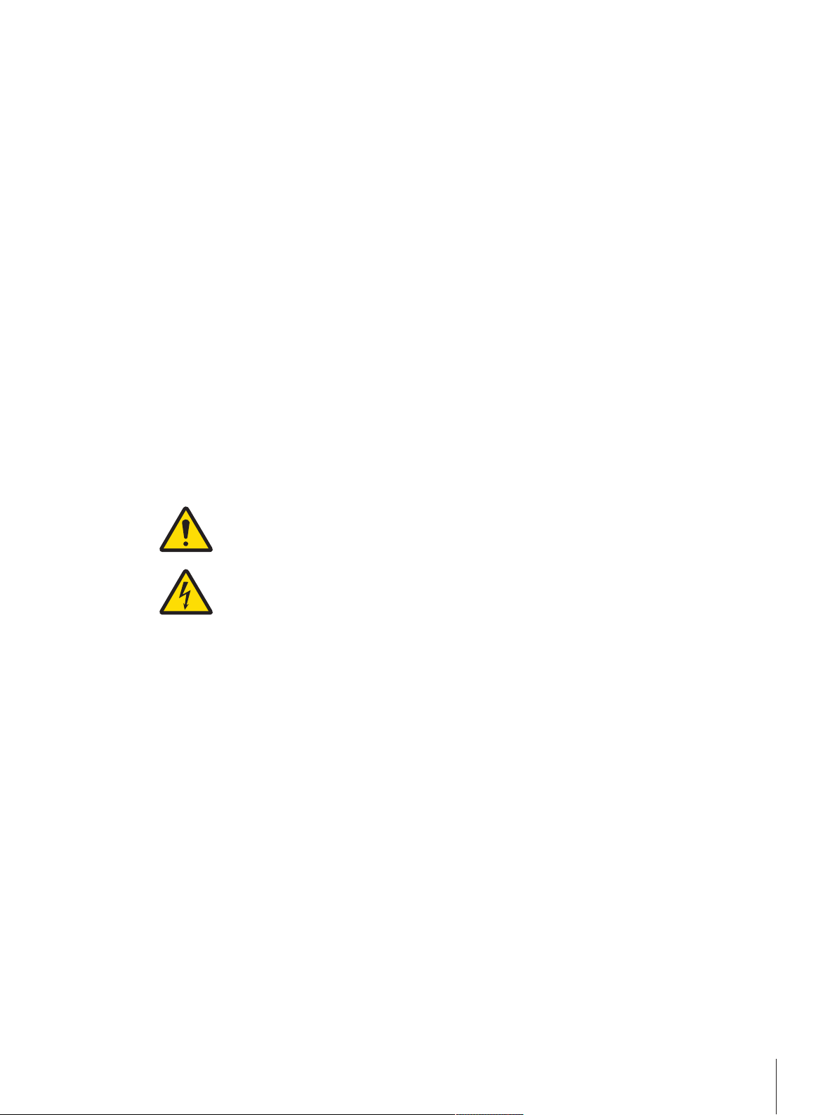
2.1 Overview
Load Cells
Housing (WXT: white
1
powder-coated, WXS:
stainless steel)
Weighing pan retainer with
2
plastic cover
Connector for electronic
3
unit
Hanger opening for
4
weighing below (on
bottom side)
Level bubble
5
Adjustable feet (WXT only)
6
Base plate with mounting
7
flange (WXS only)
Electronic units
Terminals
Housing (WXT: white
8
powder-coated, WXS:
stainless steel)
Load cell connector
9
Terminal connector
10
Optional interface plug-in
11
“Aux” connectors (for
12
“ErgoSens,” hand or footoperated buttons)
RS232-C standard
13
interface
Connector for AC adapter
14
Display (PWT: color, SWT:
15
monochrome)
Keyboard
16
“SmartSens” sensors
17
(PWT only)
Installation 5Weigh Modules
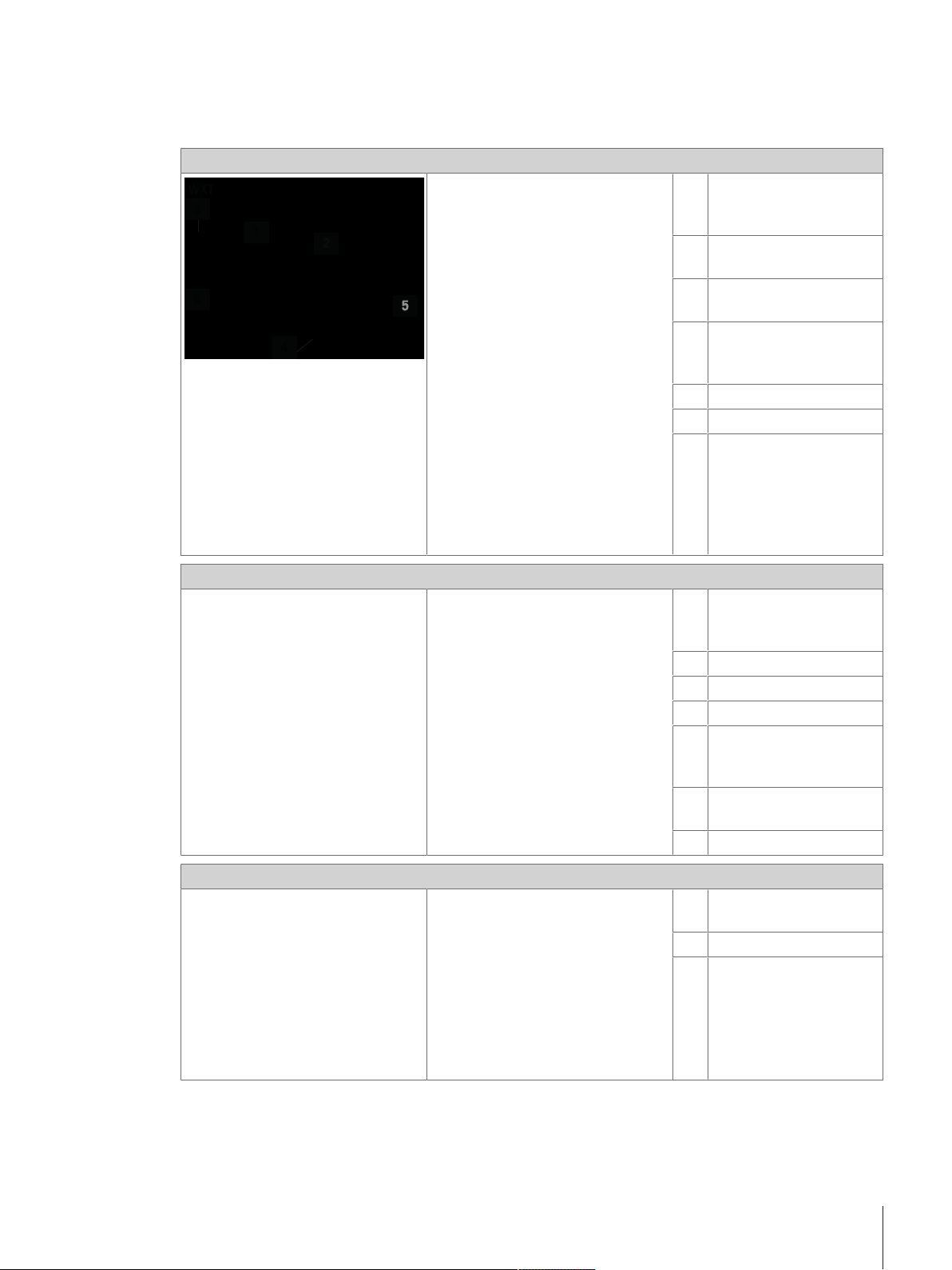
Connecting cables
Weighing pans
Electronic unit – load cell
18
connector cable (0.5m,
1.5m or 5m)
Note
Maximum allowable cable
length: 5m.
Terminal – electronic unit
19
connector cable (0.5m,
1m or 2m)
Note
Maximum allowable cable
length: 2m.
Standard weighing pan
20
Adapter weighing pan (not
21
for WXTS3DU)
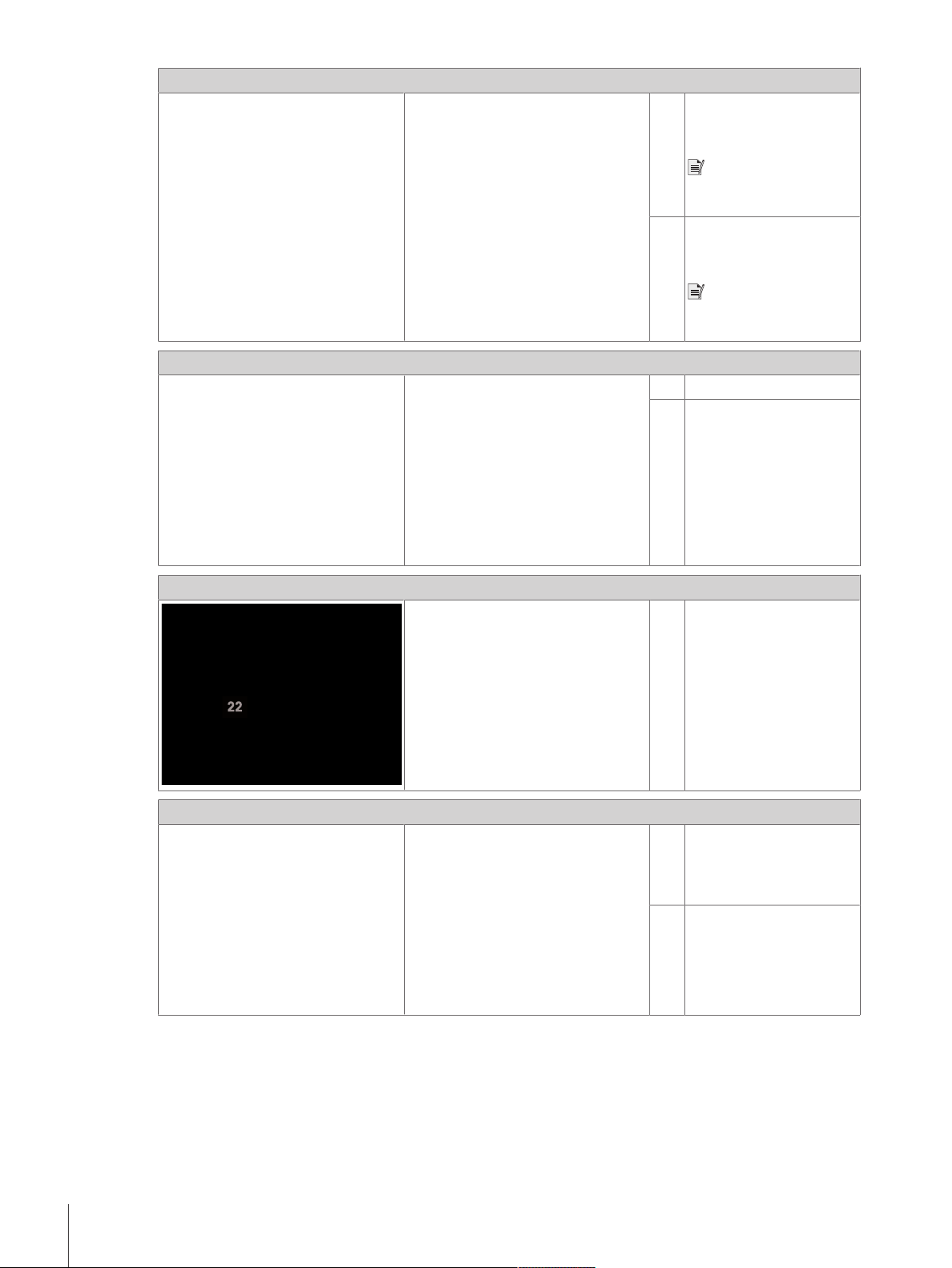
Wind ring
Mounting materials
Wind ring
22
Mounting bracket for WXS
23
electronic unit, including
DIN clip and screws (not
for WXTS3DU)
Terminal holder for SWT
24
terminal, including screws
(not for WXTS3DU)
Installation6 Weigh Modules
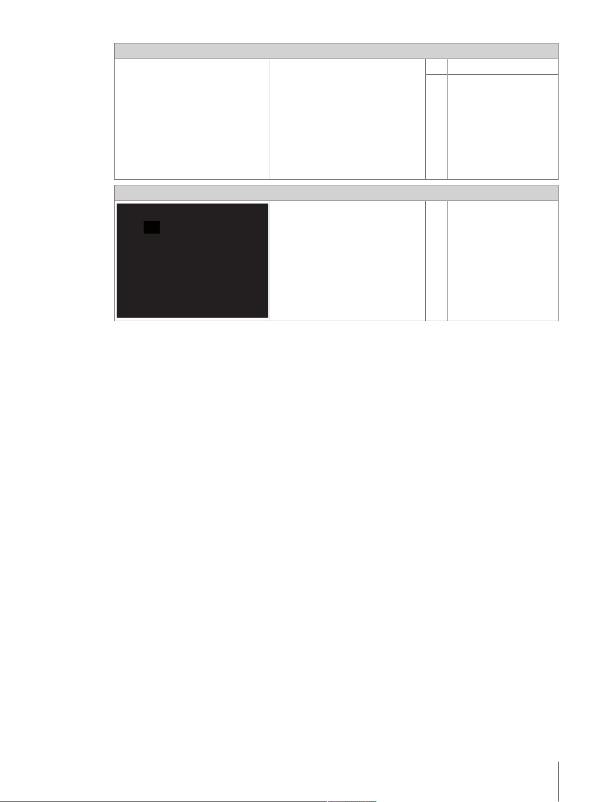
Power supply
27
Wind shield
AC adapter
25
Power cable (country-
26
specific)
WXTS3 wind shield (only
27
for WXTS3DU)
2.2 Assembling the WXS weigh module
The WXS (component version) weigh modules can be integrated into higher-level systems (machines,
systems, etc.). Be sure to follow the tips in the following sections to select the optimal installation method.
2.2.1 Load cell installation
The weigh modules were designed to record weights very quickly and accurately under normal conditions and
communicate the result using the integrated interface and/or display the result on a terminal. In practice,
ambient conditions (vibration, oscillations, shocks, air movements and temperature changes) affect weighing
time and achievable accuracy as well as the repeatability.
You can adjust various parameters on your weigh module. We recommend that you adjust the settings to the
levels needed for your application; higher requirements increase the weighing time (period between the
placement of the weight and the availability of a stable result). Filter settings must be stricter to compensate for
unfavorable ambient conditions, this also has a negative impact on weighing time. See [Configuring weigh
module}Page22].
Therefore, be sure to note the following:
Installation 7Weigh Modules
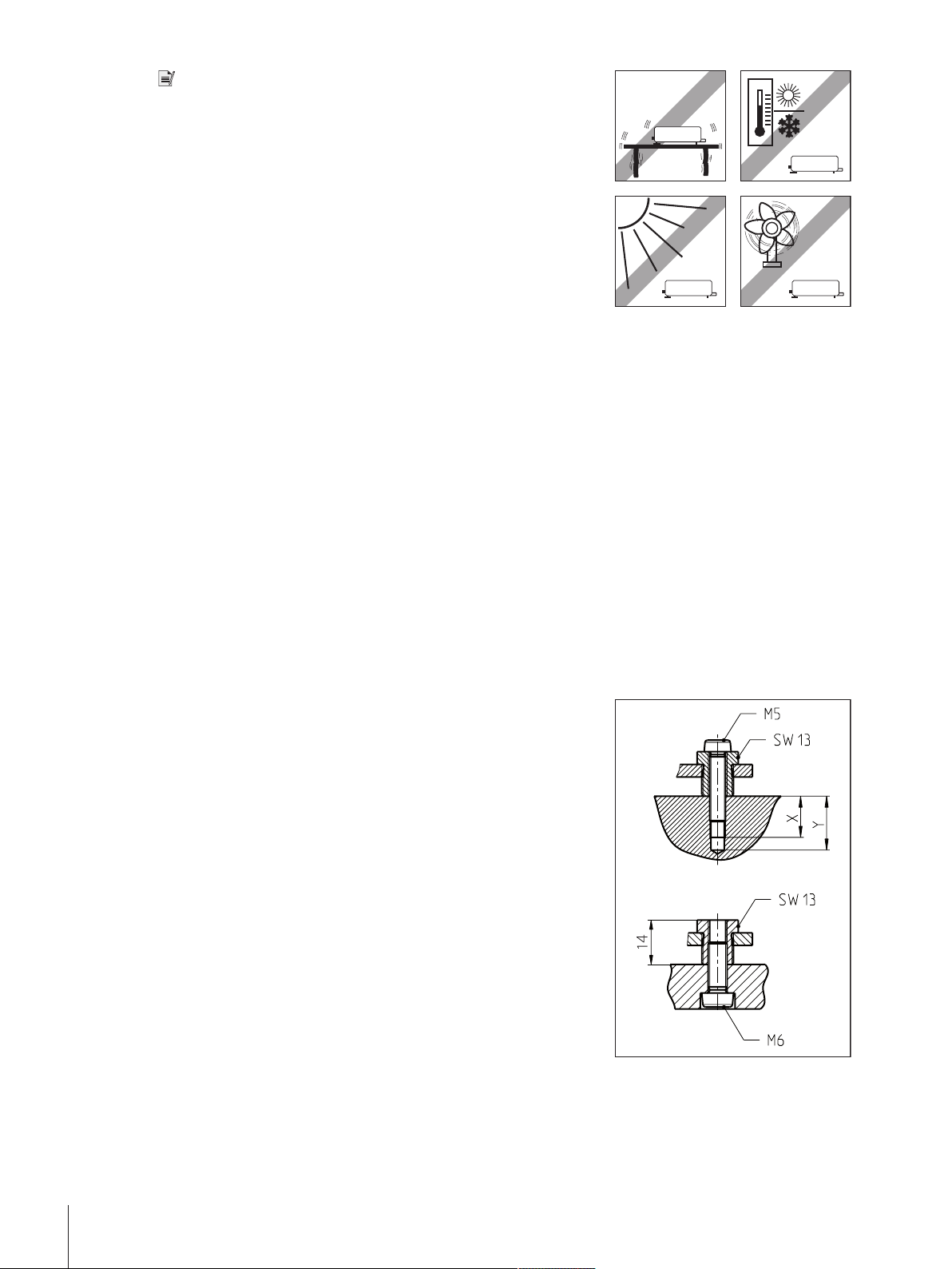
Note
• The location of the load cell should not be in areas that are
exposed to drafts, direct sunlight, or severe temperature fluctuations.
Make sure that any vibrations in the building are not transferred
through the floor and to the load cell.
• Make sure that the load cell is as perfectly horizontal as possible.
1 Mount the load cell on a base that is mechanically decoupled from
the system and therefore free of shocks and vibration.
If a mechanical decoupling is not possible, place appropriate
cushioning between the system and the load cell mount.
2 Use the built-in precision level to achieve exact leveling.
It is acceptable to have a unit that is not perfectly horizontal if its
position is not altered after it has been adjusted (e.g., if it is
mounted in a fixed position in the system). If a weigh module is
installed permanently (not moveable), it can be approved even
without having an integrated level bubble.
Weighing module WXS204/205 and WXT204/205
1 Attach the load cell to the base across as wide an area as
possible.
2 Use the appropriate bores in the front part of the cell’s base plate
(4 × M5 screws, tightening torque 4 – 6Nm).
The base must be perfectly planar to avoid putting tension on the
load cell base plate.
3 Make sure that vibrations cannot be transferred across the
connector cable between the load cell and the electronic unit.
4 Make sure that the load cell housing is connected in an electrically
conductive manner with the machine structure.
Weighing module WXS26, WXT26, WXTS3DU
1 Place the weigh module on a flat surface.
2 Levelling the module with the three leveling nuts (SW13).
3 Fix the weigh module from above by means of screws M5 × 22 or
from below with M6 screws.
4 Make sure that vibrations cannot be transferred across the
connector cable between the load cell and the electronic unit.
5 Make sure that the load cell housing is connected in an electrically
conductive manner with the machine structure.
If your requirements are extremely demanding (short weighing time, high accuracy), we recommend that you
try a test setup first and test the entire system under real-world conditions using various settings. This will allow
you to tweak the system and optimize it bit by bit.
Installation8 Weigh Modules
2.2.2 Electronic unit assembly and mounting
1
1
2
The electronic unit can be mounted in any position you wish. A mounting bracket and clip for attaching the unit
to a DIN standardized rail are provided. Proceed as follows for mounting:
Note
The electronic unit meets the requirements for protection class IP40. If required, appropriate protective measures
must be taken to protect the unit from dirt.
1 Remove the two existing screws from the bottom side of the
electronic unit (Torx T-20).
2 Use the provided Torx T-20 countersunk head screws (1) to secure
the mounting bracket.
3 Secure the clip (2) to the front face or underside of the mounting
bracket.
4 Use the two provided M4 pan head screws (Torx T-20) to do so.
Note
The electronic unit can also be attached directly to a support (without
the clip) via the M4 threads of the mounting bracket.
2.3 Weigh module WXT setup
The WXT weigh module (benchtop version) does not require any assembly work. Note the information in the
following sections about choosing an optimal location and leveling the load cell.
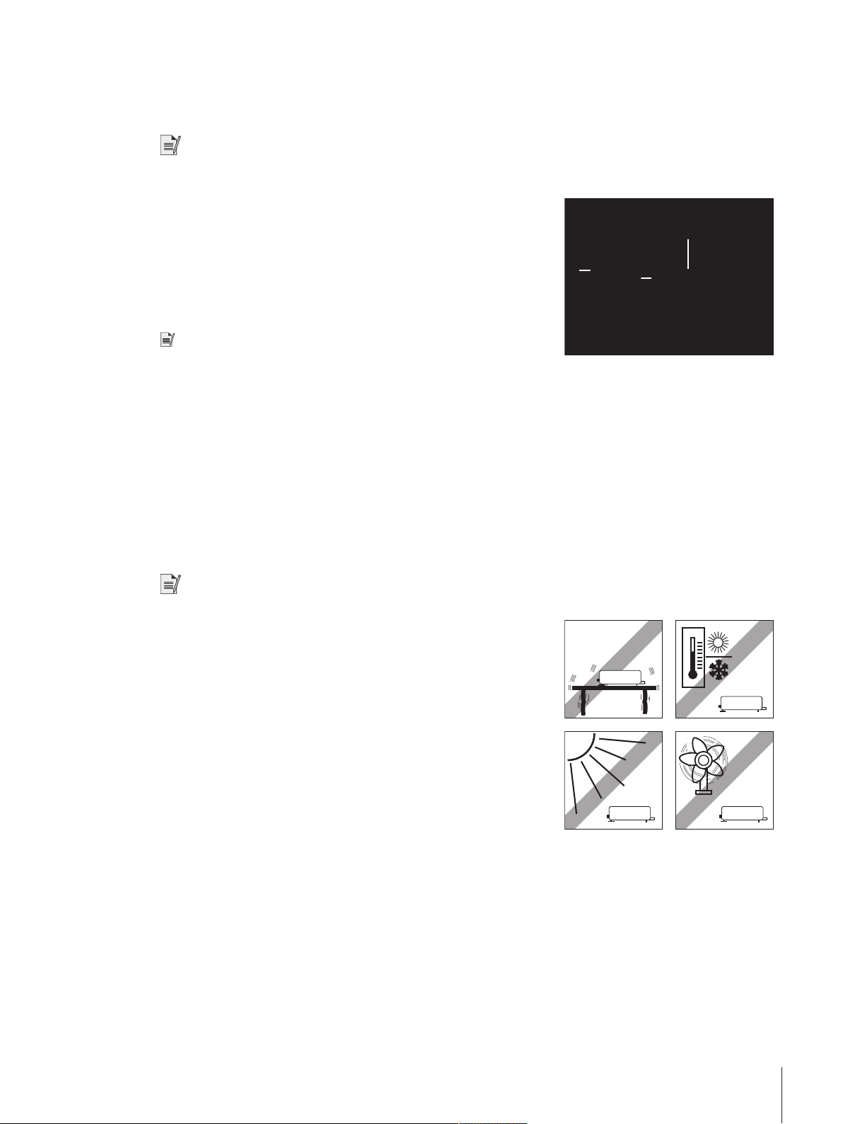
2.3.1 Choosing a location
An optimal location will ensure accurate and reliable operation of the weigh module. The surface must be able
to safely take the weight of the weigh module when fully loaded. The following local conditions must be
observed:
Note
If the weigh module is not horizontal at the outset, it must be leveled during commissioning.
• The weigh module must only be used indoors and up to a
maximum altitude of 4000 m above sea level.
• Before switching on the weigh module, wait until all parts are at
room temperature (+5 to 40°C).
The humidity must be between 10% and 80% non-condensing.
• The power plug must be accessible at all times.
• Firm, horizontal and vibration-free location.
• Avoid direct sunlight.
• No excessive temperature fluctuations.
• No strong drafts.
2.3.2 Levelling load cell
Once the load cell has been set up at the desired location, the load cell must be horizontally aligned (leveled).
The load cell have a level (level bubble) and two adjustable leveling feet to compensate for slight irregularities
in the surface of the weighing bench.
Installation 9Weigh Modules
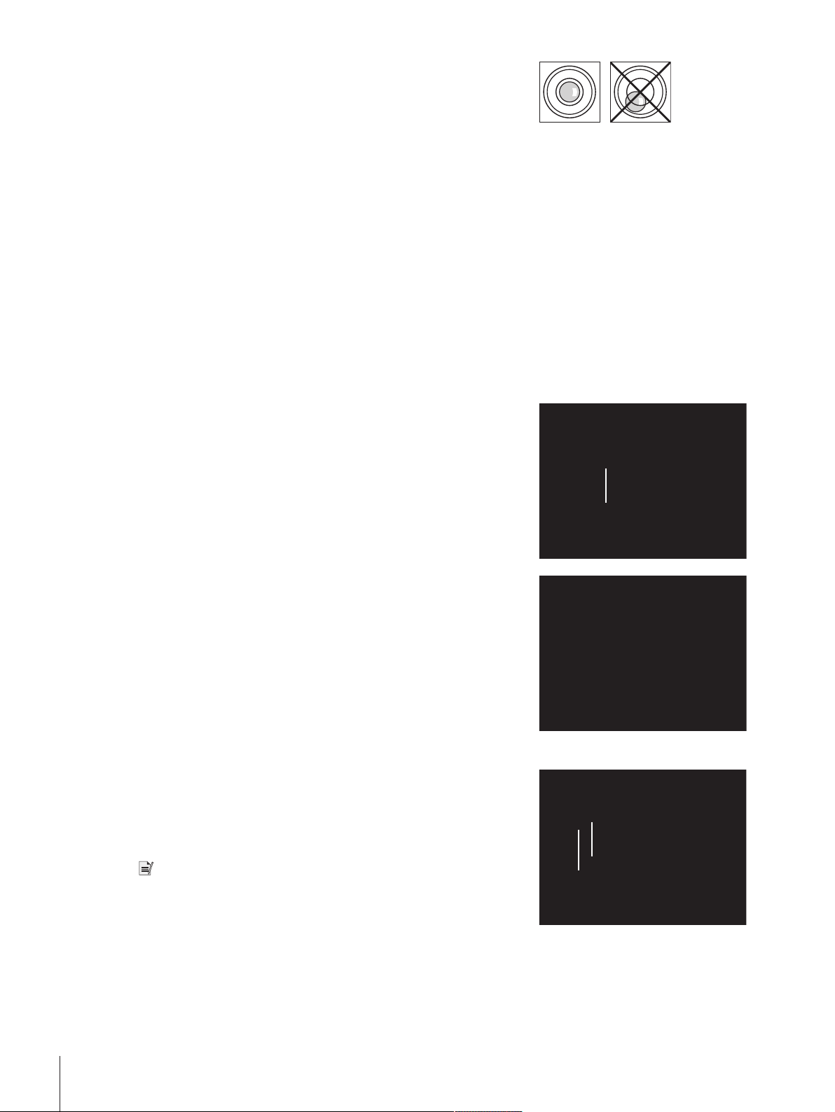
The load cell is exactly horizontal when the air bubble is in the
1
2
1
3
2
§
middle of the level glass.
1 Adjust the two leveling feet appropriately until the air bubble comes
to rest exactly in the middle of the glass:
Air bubble at "12 o'clock" turn both feet counterclockwise. Air
bubble at "3 o'clock" turn left foot clockwise, right foot counterclockwise.
Air bubble at "6 o'clock" turn both feet clockwise. Air bubble at "9
o'clock" turn left foot counterclockwise, right foot clockwise.
2 The load cell must be leveled and adjusted each time it is moved
to a new location.
2.4 Installing the weighing pan
The WXS and WXT weigh modules come with two weighing pans: a standard weighing pan and an adapter
weighing pan for users to create their own setups.
2.4.1 Installing standard weighing pan
Weighing module WXS204/205 and WXT204/205
1 Remove the white plastic cover (1) from the load cell.
This cover protects the weighing pan retainer (2) from damage
during transport and keeps liquid out of the load cell during
cleaning.
2 Make sure you keep the cover in a safe place!
− Place the standard weighing pan into the weighing pan retainer.
No specific position needed; the standard weighing pan turns
freely.
Weighing module WXS26, WXT26, WXTS3DU
1 Remove the white plastic cover (1) from the load cell.
This cover protects the weighing pan retainer (2) from damage
during transport and keeps liquid out of the load cell during
cleaning.
2 Make sure you keep the cover in a safe place!
Note
Do not remove any spacers (3)!
Installation10 Weigh Modules
− Place the wind ring.
1
2
3
Adapter weiging pan: approx. 10 g
:
55 g ... 78 g
without loosing weighing range
− Install the standard weighing pan. Turn it until it snaps into place.
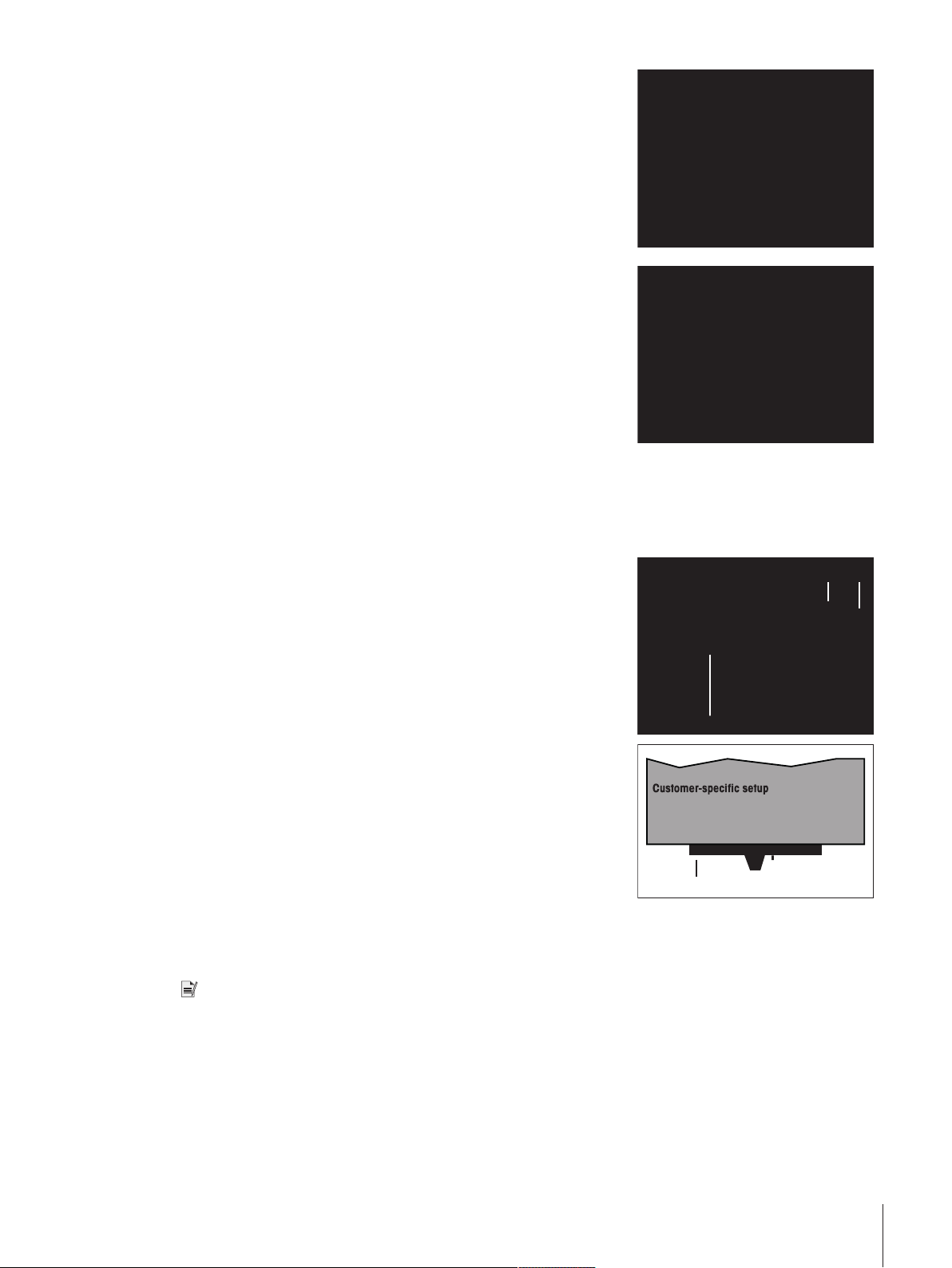
2.4.2 Installing adapter weighing pan
The adapter weighing pan is used for customer-specific setups to hold the object to be weighed.
Weighing module WXS204/205 and WXT204/205
1 Attach the customer-specific setup to the adapter weighing pan
using the three 120° offset M3 threaded holes (1).
For the exact dimensions of the adapter weighing pan, see
[WXS204/WXS205DU/WXS205, WXT204/WXT205DU/WXT205
adapter weighing pan}Page41].
2 Keep in mind that your setup must weigh at least 55g. Ensure
that the required dead load of 65g (adapter weighing pan +
setup) is reached.
ð If the required dead load is not reached, the weigh module will
output an underload error message upon startup.
3 To preserve the full weighing range, the total preload (adapter
weighing pan + setup) may not exceed 88g.
Heavier preloads will take away from the available weighing range.
Because customer-specific setups generally remain in a fixed position,
the adapter weighing pan has a positioning pin (2). This pin fits
perfectly in the two grooves in the weighing pan retainer (3) and
prevents the weighing pan from turning freely. However, this antidisplacement measure works only up to a certain torque. If this torque
is exceeded, the weighing pan turns to prevent damage to the load
cell. At the same time, the weighing pan retainer serves a protection
from lateral forces.
Note
Legal-for-trade weigh modules have a start-up dead load range from
65g to 88g (adapter weighing pan + setup). After power up the
available zero setting range is 20g.
Installation 11Weigh Modules

Weighing module WXS26, WXT26, WXTS3DU
1
2
3
Adapter weiging pan: approx. 7.2 g
:
13.8 g ... 15.8 g
without loosing weighing range
1 Attach the customer-specific setup to the adapter weighing pan
using the three 120° offset M3 threaded holes (1).
For the exact dimensions of the adapter weighing pan, see
[WXS204/WXS205DU/WXS205, WXT204/WXT205DU/WXT205
adapter weighing pan}Page41].
2 Keep in mind that your setup must weigh at least 13.8g. Ensure
that the required dead load of 21g (adapter weighing pan +
setup) is reached.
ð If the required dead load is not reached, the weigh module will
output an underload error message upon startup.
3 To preserve the full weighing range, the total preload (adapter
weighing pan + setup) may not exceed 23g.
Heavier preloads will take away from the available weighing range.
Because customer-specific setups generally remain in a fixed position,
the adapter weighing pan has a positioning pin (2). This pin fits
perfectly in the two grooves in the weighing pan retainer (3) and
prevents the weighing pan from turning freely. However, this antidisplacement measure works only up to a certain torque. If this torque
is exceeded, the weighing pan turns to prevent damage to the load
cell. At the same time, the weighing pan retainer serves a protection
from lateral forces.
Note
Legal-for-trade weigh modules have a start-up dead load range from
21g to 23g (adapter weighing pan + setup). After power up the
available zero setting range is 2g.
2.5 Installing the wind shield (only for WXTS3DU)
1 Remove the plastic cover from the pan retainer.
2 Install the wind shield on the load cell.
Installation12 Weigh Modules
3 Install the wind ring in the weighing chamber.
1
Note
Place the wind ring around the pan retainer and turn on the wind ring
until it snaps into place.
4 Install the standard weighing pan.
Note
Place the weighing pan into the pan retainer and turn on the weighing
pan until it snaps into place.
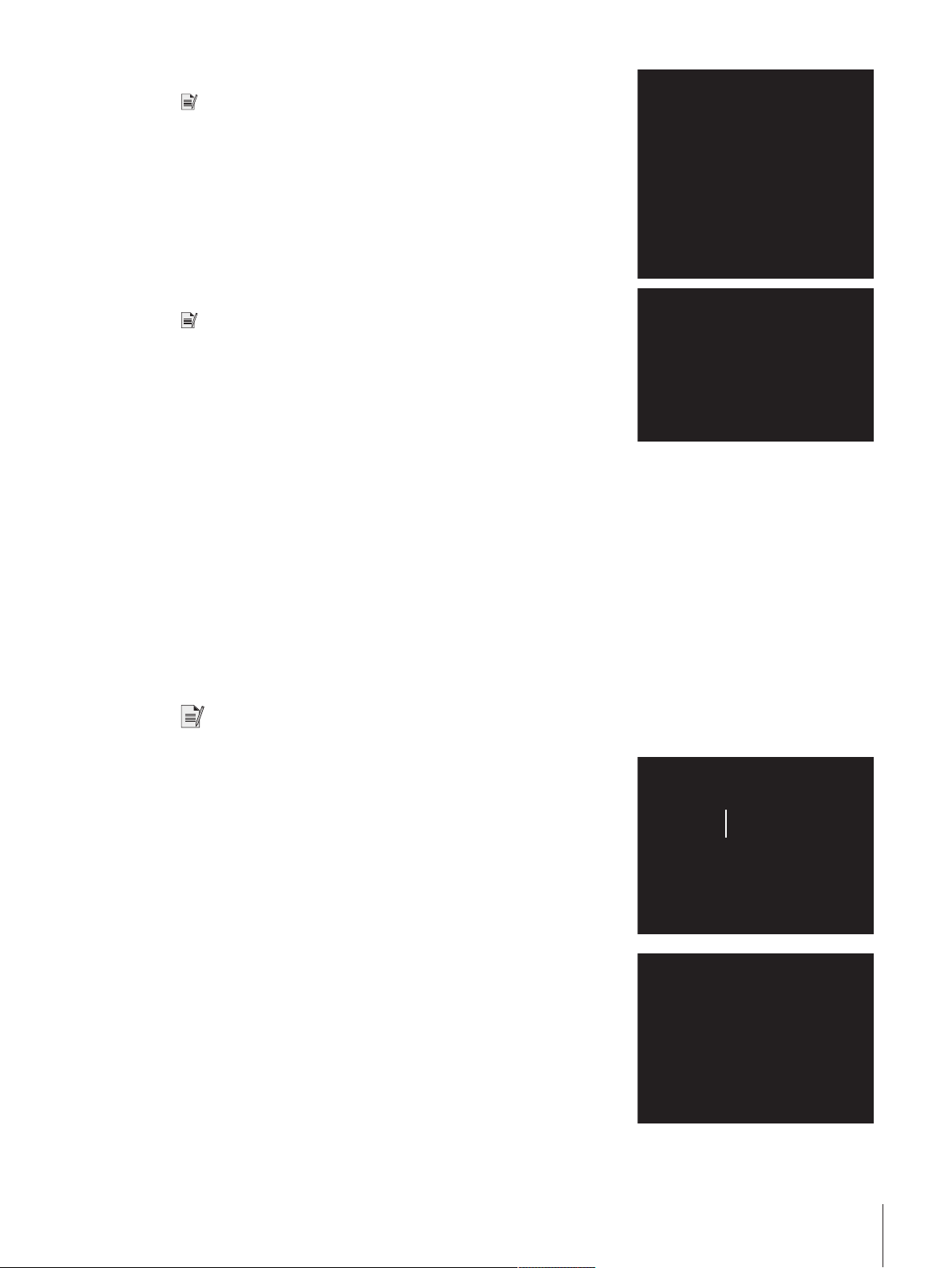
2.6 Weighing below the balance
For weighing beneath the work area (weighing below), the load cell is equipped with a hanger opening. For
weighing below, the item to be weighed is not placed on the weighing pan; it is placed on an applicationspecific receptacle attached beneath the load cell. For weighing below, the standard weighing pan is removed,
and the weighing pan retainer is closed up using the plastic cover so that dirt and foreign matter cannot
penetrate the load cell.
Here are some examples of when weighing below is used:
• when it is difficult or impossible to put the material to be weighed on the weighing pan
• when space will not allow for items to be weighed from above
• when weighing from above might soil or contaminate the load cell
Note
Weighing below is not allowed when using legal-for-trade versions.
The hanger opening is on the bottom of the cell under a round cover
(1).
You’ll need the optional weighing below adapter, which should be
installed by a METTLER TOLEDO service technician if possible, to
attach the customer-specific receptacle. For information on how to
order, see [Accessories}Page48].
Installation 13Weigh Modules
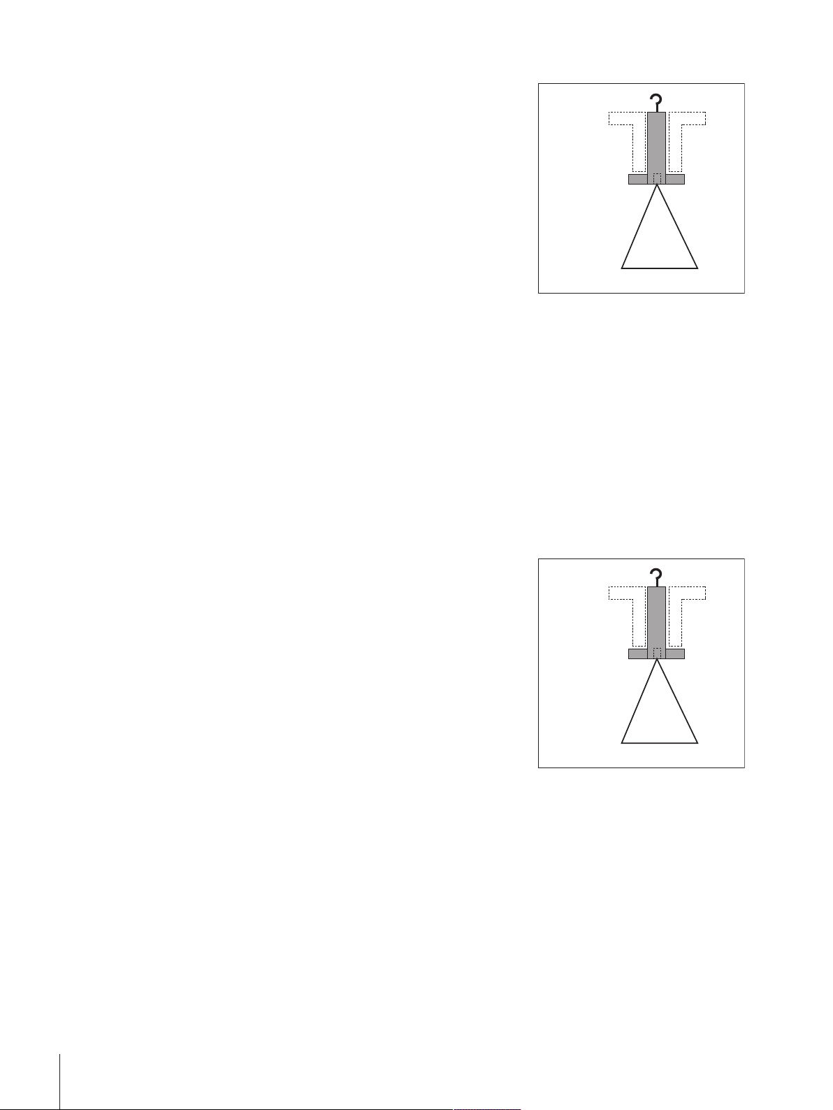
Weighing module WXS204/205 and WXT204/205
Fixture:
52 g ... 75 g without loosing weighing range
Weighing below
adapter: 13 g
Fixture:
52 g ... 75 g without loosing weighing range
Weighing below
adapter: 13 g
Please keep the following in mind when planning a weighing below
receptable for objects to be weighed:
The fixture must weigh at least 52g.
1 Ensure that the required dead load of 65g (weighing below
adapter + fixture).
ð If the required dead load is not reached, the weighing module
will output an underload error message upon startup.
2 To preserve the full weighing range, the total weight of the weighing
below adapter and fixture may not exceed 88g.
3 Take heavier preloads away from the available weighing range.
4 Secure the fixture to the M4 thread of the weighing below adapter
(max. penetration depth: 8mm, max. tightening torque: 1Nm).
5 Position the fixture’s center of gravity as close to and vertically
beneath the attachment point as possible.
ð The weighing receptacle must hang freely from the attachment
point of the weighing below adapter without touching nonmoving parts of the load cell or the system. The maximum
diameter or cross-section of the fixture at the attachment point
is 8mm.
6 Limit the vertical and horizontal movement and/or torsion of the
fixture by using mechanical stops to prevent overload of the load
cell.
7 To minimize weighing time, avoid vibrations and shocks to the
fixtures and the objects to be weighed.
Weighing module WXS26, WXT26, WXTS3DU
Please keep the following in mind when planning a weighing below
receptable for objects to be weighed:
The fixture must weigh at least 8g.
1 Ensure that the required dead load of 21g (weighing below
adapter + fixture).
ð If the required dead load is not reached, the weighing module
will output an underload error message upon startup.
2 To preserve the full weighing range, the total weight of the weighing
below adapter and fixture may not exceed 23g.
3 Take heavier preloads away from the available weighing range.
4 Secure the fixture to the M4 thread of the weighing below adapter
(max. penetration depth: 8mm, max. tightening torque: 1Nm).
5 Position the fixture’s center of gravity as close to and vertically
beneath the attachment point as possible.
ð The weighing receptacle must hang freely from the attachment
point of the weighing below adapter without touching nonmoving parts of the load cell or the system. The maximum
diameter or cross-section of the fixture at the attachment point
is 8mm.
6 Limit the vertical and horizontal movement and/or torsion of the
fixture by using mechanical stops to prevent overload of the load
cell.
7 To minimize weighing time, avoid vibrations and shocks to the
fixtures and the objects to be weighed.
Installation14 Weigh Modules
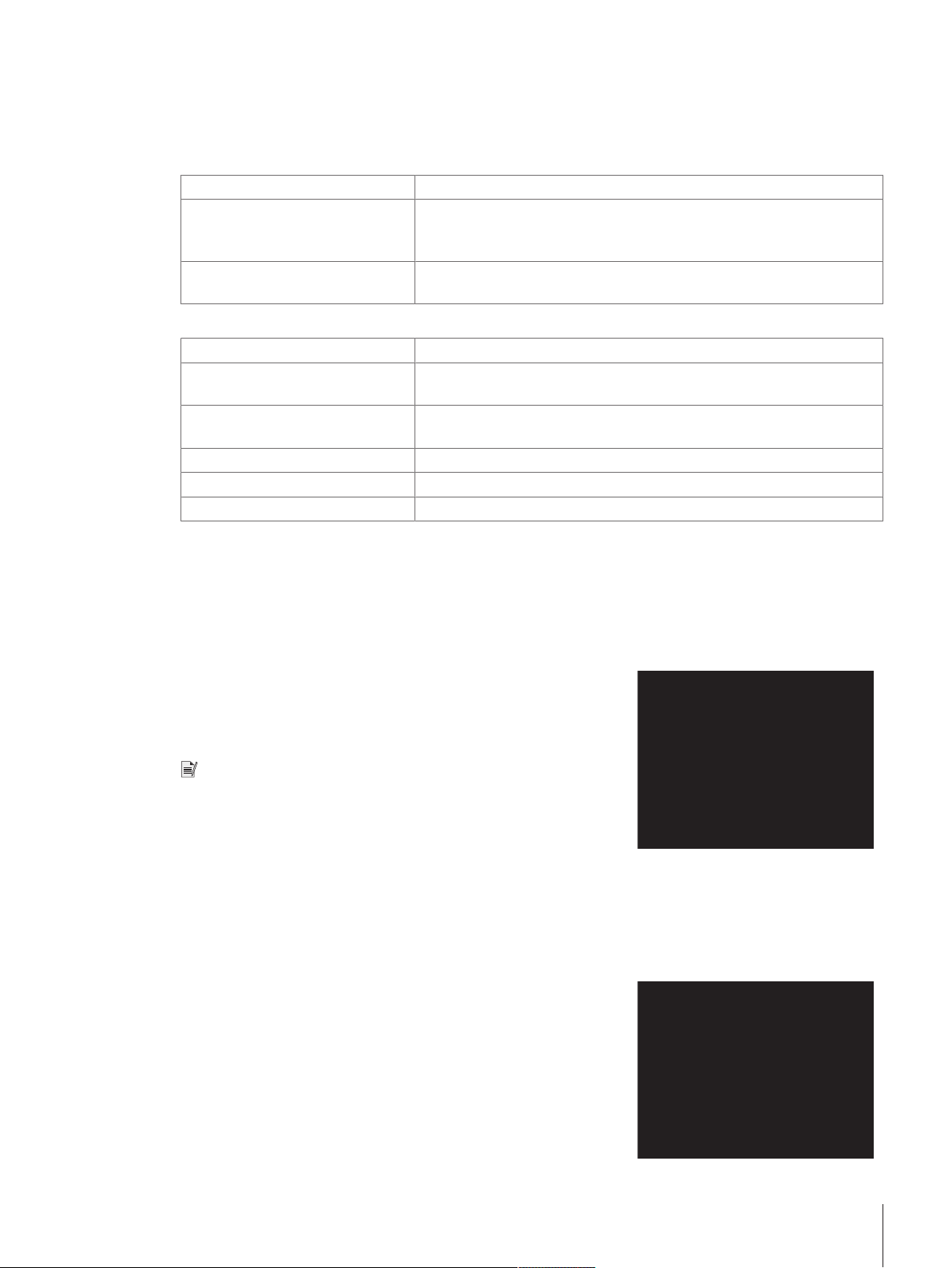
2.7 Overload protection
1
1
2
The WXS/WXT weigh modules have overload protection that is effective in all directions up to the following limit
values:
Weighing module WXS204/205 and WXT204/205
Vertical load: 5kg * (all types; centered load)
Lateral load: 1kg (protected by torsion protection; see [WXS204/WXS205DU/
WXS205, WXT204/WXT205DU/WXT205 adapter weighing
pan}Page41].
Torsion: Protected by torsion protection, see [WXS204/WXS205DU/WXS205,
WXT204/WXT205DU/WXT205 adapter weighing pan}Page41].
Weighing module WXS26, WXT26, WXTS3DU
Vertical load: 1 kg * (all types; centered load)
Lateral load: 0.1 kg (protected by torsion protection; see [WXS26/WXT26 adapter
weighing pan}Page42].
Torsion: Protected by torsion protection, see [WXS26/WXT26 adapter weighing
pan}Page42].
Weighing below "push": 0.1 kg
Weighing below "pull": 0.1 kg
Weighing below "torsion": No overload protection
* if wind ring and weighing pan are mounted properly.
2.8 Connect load cell and electronic unit
Legal-for-trade
With the exception of legal-for-trade weigh modules the load cell and the electronic unit can be replaced
independently of each other if necessary.
1 Use the provided cable (0.5m or 1.5m) to connect the load cell
to the electronic unit.
2 Tighten the plugs on both devices.
A 5m cable is available as an accessory.
Note
Lay the cable so that no one will trip over it and so that no vibrations
can travel up the cable and be transferred to the load cell.
2.9 Connect terminal and adjust settings
You’ll need this section only if your weigh module was delivered with a terminal.
2.9.1 SWT terminal
1 Place the terminal on a flat surface with the display face down.
2 Press the two tabs (1) on the back of the terminal to open it.
3 Open the bottom of the terminal (2).
Installation 15Weigh Modules

4 Feed the terminal cable through the cutout in the back of the
3
4
6
5
7
8
7
1 1
2
terminal and plug in the jack (3).
5 Make sure that the strain relief (4) is inside the terminal.
If you want to permanently affix the terminal to the electronic unit, you
can also attach the terminal holder now:
6 Place the terminal holder (5) into the corresponding cutout on the
bottom of the terminal.
7 Use the knurled screw (6) provided to secure it from the inside of
the terminal.
8 Close the bottom of the terminal.
9 Push in the two side tabs to completely close the terminal.
ð You can also use the two side tabs to adjust the viewing angle
of the terminal while it is in operation.
10 Press both buttons simultaneously and pull the top of the terminal
gently upwards, or press it down until it clicks into the desired
position.
11 You can choose from three different positions.
12 Remove the two screws (Torx T-20) in the bottom of the electronic
unit and store them in a safe place.
13 Align the terminal holder exactly with the two bores and secure it
with the Torx T-20 countersunk head screws (7).
14 Plug the terminal cable plug (8) into the appropriate jack on the
back of the electronic unit and screw in to tighten.
15 Try to run the terminal cable as close as parallel as possible to the
terminal holder.
2.9.2 PWT terminal
1 Place the terminal on a flat surface with the display face down.
2 Press the two tabs (1) on the back of the terminal to open it.
3 Open the bottom of the terminal (2).
Installation16 Weigh Modules
 Loading...