

Page 1

User manual
METTLER TOLEDO
Weighing terminal IND445
www.mt.com/support
Page 2

Congratulations on choosing the quality and precision of METTLER TOLEDO. Proper
use according to this Operating Manual and regular calibration and maintenance by
our factory-trained service team ensures dependable and accurate operation,
protecting your investment. Contact us about a ServiceXXL agreement tailored to your
needs and budget.
We invite you to register your product at www.mt.com/productregistration
so we can
contact you about enhancements, updates and important notifications concerning
your product.
@@@@@
Page 3

Table of contentsIND445
3User manual 22013194B 05/08
Table of contents
Page
1 Introduction .....................................................................................5
1.1 Safety instructions .............................................................................5
1.2 Description ......................................................................................6
1.3 Putting into operation ........................................................................9
1.4 Disposal ........................................................................................10
2 Operation ......................................................................................11
2.1 Switching on and off .......................................................................11
2.2 Zeroing / Zero point correction ..........................................................11
2.3 Simple weighing .............................................................................11
2.4 Weighing with tare ..........................................................................12
2.5 Displaying the capacity available ......................................................13
2.6 Dynamic weighing ..........................................................................14
2.7 Weighing-in to a target weight and checkweighing .............................15
2.8 Working with identifications .............................................................16
2.9 Printing results ...............................................................................17
2.10 Displaying info ...............................................................................17
2.11 Switching scales .............................................................................18
2.12 Accumulating .................................................................................18
2.13 Cleaning ........................................................................................19
3 Counting .......................................................................................20
3.1 Counting parts into a container .........................................................20
3.2 Counting parts out of a container ......................................................20
3.3 Counting with operator guidance ......................................................21
3.4 Counting with variable reference quantity ...........................................22
3.5 Counting with minimum accuracy ....................................................22
3.6 Reference optimization ....................................................................23
3.7 Counting with automatic reference determination ................................23
3.8 Counting with a known average piece weight ....................................23
3.9 Counting by calling up a saved average piece weight .........................24
3.10 Counting by calling up a saved target quantity ...................................25
3.11 Counting with two scales .................................................................26
4 Settings in the menu ......................................................................28
4.1 Operating the menu ........................................................................28
4.2 Overview .......................................................................................30
4.3 Scale settings (SCALE) ....................................................................34
4.4 Application settings (APPLICATION) ..................................................36
4.5 Terminal settings (TERMINAL) ..........................................................40
4.6 Configuring interfaces (COMMUNICATION) .........................................42
4.7 Diagnosis and printing out of the menu settings (DIAGNOS) ................46
Page 4

IND445
4
Table of contents
User manual 22013194B 05/08
5 Interface description ......................................................................48
5.1 SICS interface commands ................................................................ 48
5.2 TOLEDO Continuous mode .............................................................50
6 Event and error messages .............................................................. 52
7 Technical data and accessories ......................................................55
7.1 Technical data ...............................................................................55
7.2 Accessories ................................................................................... 58
8 Appendix ...................................................................................... 59
8.1 Safety checks ................................................................................. 59
8.2 FCC .............................................................................................. 59
9 Index ............................................................................................60
Page 5
IntroductionIND445
5User manual 22013194B 05/08
1 Introduction
1.1 Safety instructions
DANGER!
Electric shock hazard!
▲ Always pull out the mains plug before any work on the device.
DANGER!
Electric shock hazard if the mains cable is damaged!
▲ Check the mains cable for damage regularly and replace it immediately if it is dam-
aged.
▲ On the rear side of the device, maintain a clearance of at least 1.2" (3 cm) in order
to prevent the mains cable bending too much.
CAUTION!
On no account open the device!
The warranty is void if this stipulation is ignored. The device may only be opened by
authorized persons.
▲ Call METTLER TOLEDO Service.
CAUTION!
Do not use IND445 in hazardous areas!
Our product range includes special devices for hazardous areas.
CAUTION!
Terminals with protection level IP65 are dust-tight and hose-proof to EN 60529. They
are suitable for use in dusty environment and brief contact with liquids. Ensure that the
terminal is dried off again after coming into contact with liquid.
Even with degree of protection IP65 the terminal should not be used in environments
in which there is a risk of corrosion.
▲ Do not flood the terminal or submerge it in liquid.
Page 6
IND445
6
Introduction
User manual 22013194B 05/08
Note Use with foodstuffs
Parts coming into contact with foodstuffs have smooth surfaces and are easy to clean.
The materials used do not splinter and are free of harmful substances.
With foodstuffs, it is recommended to use the protective cover, see section 7.2 Accessories.
➜ Clean the protective cover regularly and carefully.
➜ Replace damaged or very dirty protective cover immediately.
1.2 Description
METTLER TOLEDO weighing platforms can be connected to the terminal IND445 without any problems.
The power supply is carried out via a built-in power supply device or an external battery.
One of the following options can also be ordered:
• Additional interface RS232 or RS485
• Ethernet interface
• USB interface
• Digital I/O
• OptionBox for
– AccuPac
– Analog second scale interface
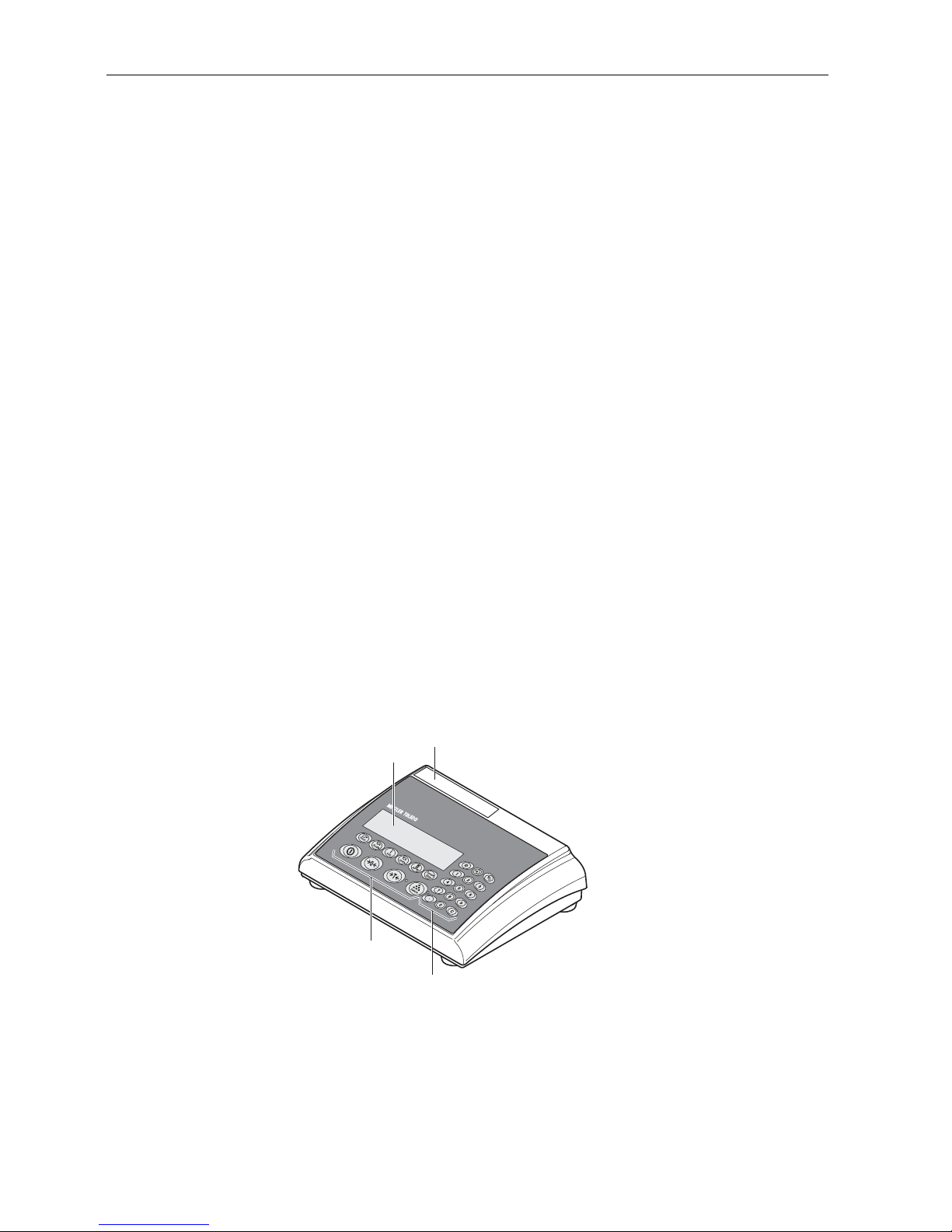
1.2.1 Overview
1 Display
2 Specifications, rating
plate
3 Numerical keys
4 Function keys
1
4
3
2
Page 7

IntroductionIND445
7User manual 22013194B 05/08
1.2.2 Display
1 Power supply
connection
2 Weighing platform
connection
3 Optional interface
4 (Standard) RS interface
321 4
1 7-segment display, 7 digits, with decimal point
2 Active interface
3 Symbol for displaying gross and net values
4 Active scale
5 Weighing range display
6 Battery charge level; only present on scales with a battery
7 Weight units
8 Selected reference quantity
9 Symbols for optimizing the average piece weight and accumulating
10 Symbol for dynamic weighing
11 Graphic display of the weighing range, display for checkweighing
12 Stability monitor (goes out when a stable weight value is reached)
13 Sign
14 Identification for changed or calculated weight values, e.g. higher resolution,
minimum weight not reached
Opt
Auto
Com 231 231
Pcs
%
kg
10010050500
%
1 34 5
6
7
8
91011
12
13
14
OK
2
Page 8

IND445
8
Introduction
User manual 22013194B 05/08
1.2.3 Keypad
Main functions
Additional functions
Key Function in operating mode Function in the menu
Switching device on / off, abort To the last menu item –End-
Setting scale to zero Scrolling back
Taring scale
The LED next to the key flashes when the
key must be pressed, if the operator guidance is activated in the menu.
Scrolling forward
Determining average piece weight and
displaying the number of pieces
The LED next to the key flashes when the
key must be pressed, if the operator guidance is activated in the menu.
No function
Transfer key
Long key press: Calling up menu
Activating menu item
Accepting selected setting
0
T
Key Function
Switching the scale
Info key: Calling up additional information, e.g. gross weight, average piece weight,
higher resolution ...
Switching weight unit
Defining average piece weight numerically
Selecting reference quantity
Entering identification
Memory
Units
APW
Page 9

IntroductionIND445
9User manual 22013194B 05/08
1.3 Putting into operation
For startup, connect the terminal to an analog METTLER TOLEDO weighing platform.
1.3.1 Connecting the power supply
CAUTION!
Before connecting the scale to the mains, check whether the voltage value printed on
the rating plate corresponds with the local mains voltage.
▲ Never connect the device if the voltage value printed on the rating plate is different
to the local mains voltage.
➜ Plug the mains plug into the socket.
After connection, the device performs a self-test. When the zero display appears,
the device is ready to weigh.
➜ Calibrate the device in order to obtain the greatest possible precision, see
Section 4.3.2.
Note The storage battery is also suitable for permanent mains operation.
➜ In order to obtain the full nominal capacity we recommend that you discharge the
storage battery at regular intervals (approx. every 4 weeks) through normal
operation.
Adding/subtracting
Clear key
Keys 0 ... 9 and decimal
point
Numerical keys for entering weight values, identifications ...
Key Function
Terminals with AccuPac can work independently from the mains for approximately
30 hours in normal operation. A prerequisite for this is that the background lighting
is switched off and that no peripheral devices are connected.
The battery symbol indicates the present charging level of the battery. 1 segment corresponds to approx. 25 % capacity. When the symbol flashes the battery must be
charged (min. 4 hours). The charging period is extended if work is continued during
charging. The battery is protected against overcharging.
The charging time of the storage battery amounts to approx. 6 hours. If the device
continues to be operated during the charging process, the charging time is extended.
The storage battery has a service life of approx. 1,000 charging/discharging cycles.
Page 10

IND445
10
Introduction
User manual 22013194B 05/08
1.4 Disposal
In conformance with the European Directive 2002/96 EC on Waste Electrical and
Electronic Equipment (WEEE) this device may not be disposed of with domestic
waste. This also applies to countries outside the EU, per their specific requirements.
➜ Please dispose of this product in accordance with local regulations at the collecting
point specified for electrical and electronic equipment.
If you have any questions, please contact the responsible authority or the distributor
from which you purchased this device.
Should this device be passed on to other parties (for private or professional use), the
content of this regulation must also be related.
Thank you for your contribution to environmental protection.
If the device is equipped with a storage battery:
The nickel metal hydride (NiMH) storage battery does not contain any heavy metals.
However, it may not be disposed of with the normal refuse.
➜ Observe the local regulations on the disposal of materials that are hazardous to the
environment.
Page 11

OperationIND445
11User manual 22013194B 05/08
2 Operation
2.1 Switching on and off
Switching on ➜ Press .
The scale conducts a display test. When the weight display appears, the scale is
ready to weigh.
Switching off ➜ Press .
Before the display goes out, -OFF- appears briefly.
2.2 Zeroing / Zero point correction
Zeroing corrects the influence of slight changes on the load plate.
Manual 1. Unload scale.
2. Press .
The zero display appears.
Automatic In the case of scales that cannot be certified, the automatic zero point correction can
be deactivated in the menu or the amount can be changed.
As standard, the zero point of the scale is automatically corrected when the scale is
unloaded.
2.3 Simple weighing
1. Place weighing sample on scale.
2. Wait until the stability monitor goes out.
3. Read weighing result.
Page 12

IND445
12
Operation
User manual 22013194B 05/08
2.4 Weighing with tare
2.4.1 Taring
➜ Place the empty container on the scale and press .
The zero display and the symbol NET appear.
The tare weight remains saved until it is cleared.
2.4.2 Clearing the tare
➜ Press .
The symbol NET goes out, and the scale goes to gross mode.
If A.CL-tr is activated in the menu, the tare weight is automatically cleared as soon
as the scale is unloaded.
2.4.3 Automatic taring
Prerequisite
A-tArE is activated in the menu under SCALE –> tArE, the symbol T flashes in
the display.
The packaging material must be heavier than 9 display steps of the scale.
➜ Place the container or packaging material on the scale.
The packaging weight is automatically saved as the tare weight, the zero display
and the symbol NET appear.
2.4.4 Numerical tare weight entry
1. Enter the known tare weight numerically and press .
The entered weight is automatically saved as the tare weight, the symbol NET and
the tare weight with a minus sign appear.
2. Place the filled container on the scale.
The net weight appears in the display.
2.4.5 Taring by calling up a saved tare value
IND445 have a total of 100 memory locations for frequently used tare values, average
piece weights, target weights and target quantities. In the factory setting, the memory
locations 01 to 40 are reserved for tare values. The saved tare values are also preserved when the scale is switched off.
Saving tare weights
1. Determine the tare weight in one of the ways described earlier.
2. Enter the memory location number (factory setting: 1 ... 40) and keep
pressed until the confirmation appears in the display, e.g. tArE.12.
T
T
Page 13
OperationIND445
13User manual 22013194B 05/08
Note If a tare weight had already been saved under the selected memory location, the mes-
sage rEPLACE appears in the display.
• To save the new tare weight, press . The old tare weight is overwritten.
• To abort the save process, press . The previous memory location assignment
remains valid.
Calling up tare weights
➜ Enter the number of the memory location with the required tare weight (factory set-
ting: 1 ... 40) and press briefly.
The selected tare value is loaded from the memory and appears briefly in the display. The scale tares with the selected tare value and then displays the current net
weight.
Clearing saved tare weights
1. Enter the number of the memory location with the tare weight to be cleared (factory
setting: 1 ... 40) and press briefly.
The saved tare value is displayed.
2. Press within 2 seconds.
CLEArED briefly appears in the display. The saved tare value is cleared.
2.4.6 Chain tare
Prerequisite
The tare function CHAIn.tr is activated in the menu.
With this function it is possible to tare several times if, for example, cardboard is
placed between individual layers in a container.
1. Place the first container or packaging material on the scale and press .
The packaging weight is automatically saved as the tare weight, the zero display
and the symbol NET appear.
2. Weigh the weighing sample and read/print out the result.
3. Place the second container or packaging material on the scale and press
again.
The total weight on the scale is saved as the new tare weight. The zero display
appears.
4. Weigh the weighing sample in the second container and read/print the result.
5. Repeat the last two steps for other containers.
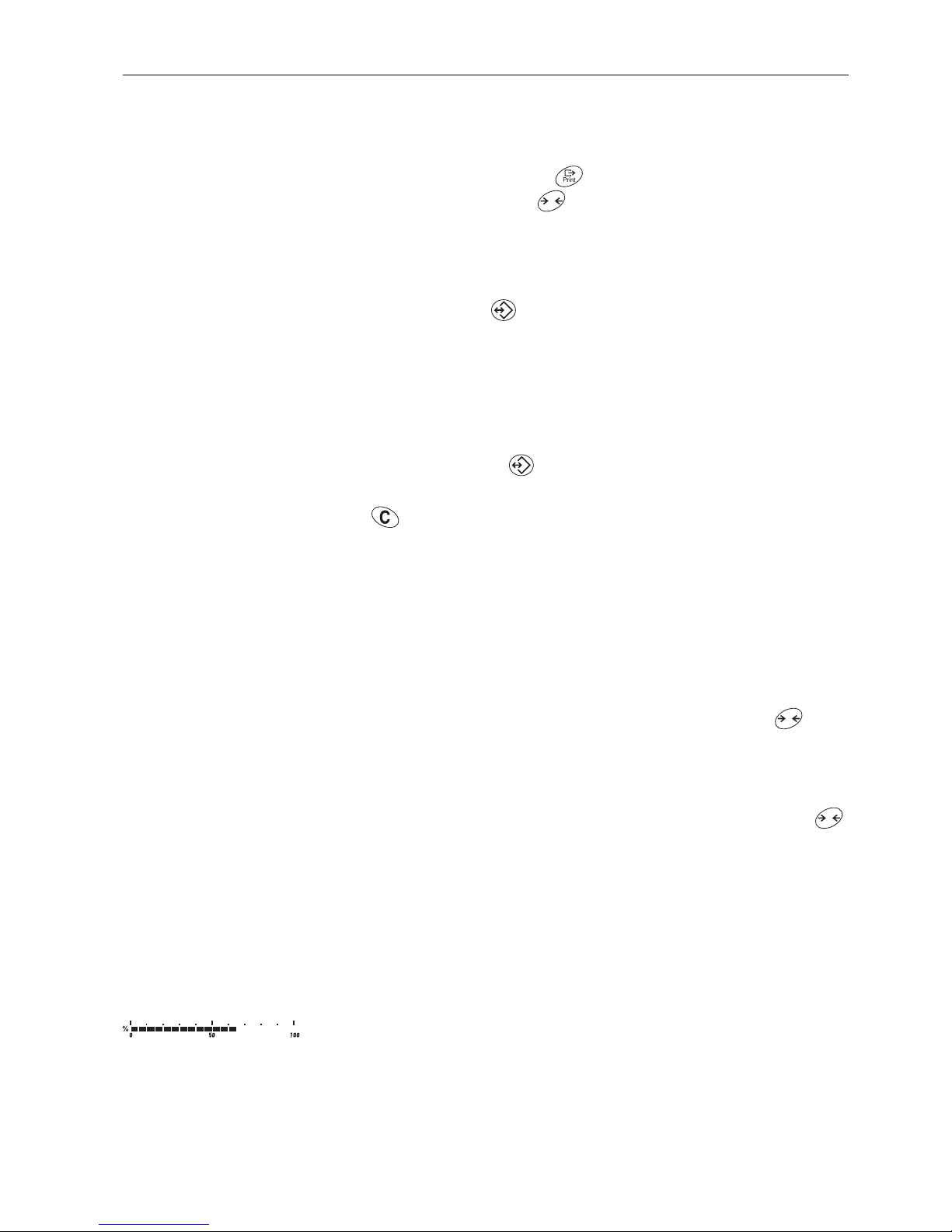
2.5 Displaying the capacity available
The scale has a graphic display of the scale capacity available. The bar indicates how
many per cent of the scale capacity is already occupied and what capacity is still
available. In the example, approx. 65 % of the scale capacity is occupied.
T
T
T
Page 14

IND445
14
Operation
User manual 22013194B 05/08
2.6 Dynamic weighing
With the dynamic weighing function, it is possible to weigh restless weighing samples
such as live animals. If this function is activated, the symbol appears in the display.
With dynamic weighing, the scale calculates the mean value from 56 weighing operations within 4 seconds.
With manual start Prerequisite
AVErAGE -> MAnuAL is selected in the menu.
The weighing sample must be heavier than 5 scale divisions.
1. Place the weighing sample on the scale and wait until it has stabilized.
2. Press to start dynamic weighing.
During dynamic weighing, horizontal segments appear in the display, and the
dynamic result is then displayed with the symbol *.
3. Unload the scale to be able to start a new dynamic weighing operation.
With automatic start Prerequisite
AVErAGE -> AUtO is selected in the menu.
The weighing sample must be heavier than 5 scale divisions.
1. Place the weighing sample on the scale.
The scale starts the dynamic weighing automatically.
During dynamic weighing, horizontal segments appear in the display, and the
dynamic result is then displayed with the symbol *.
2. Unload the scale to be able to perform a new dynamic weighing operation.
Page 15
OperationIND445
15User manual 22013194B 05/08
2.7 Weighing-in to a target weight and checkweighing
The terminal IND445 allows the weighing-in of goods to a particular target weight
within defined tolerances. With this function it is possible to check whether weighed
materials are within a defined tolerance range.
The terminal IND445 has a total of 100 memory locations for frequently used tare values, average piece weights, target weights and target quantities. In the factory setting,
the memory locations 81 to 90 are reserved for target weights. The saved target
weights are also preserved when the terminal is switched off.
2.7.1 Saving target weights
1. Enter the memory location number (factory setting: 81 ... 90) and keep
pressed until the confirmation tArGEt appears in the display.
2. Enter the target weight in the defined unit, e.g. 1.5 kg, and confirm with .
The display tOLER appears and + flashes.
3. Enter the upper tolerance in the displayed weight unit, e.g. 0.1 kg, and confirm with
:
-or-
➜ Press , enter the upper tolerance range in per cent and confirm with .
The display tOLEr appears and – flashes.
4. Enter the lower tolerance accordingly.
The scale returns to weighing mode.
Note If a target weight had already been saved under the selected memory location, the
message rEPLACE appears in the display.
• To save the new target weight, press . The old target weight is overwritten.
• To abort the save process, press . The previous memory location assignment
remains valid.
2.7.2 Calling up target weights
➜ Enter the number of the memory location with the required target weight (factory
setting: 81 ... 90) and press briefly.
The selected target weight and the tolerances are loaded from the memory and
appear briefly in the display. The scale is now ready for weighing-in or checkweighing.
T
Page 16

IND445
16
Operation
User manual 22013194B 05/08
2.7.3 Weighing-in
1. Place the empty container on the scale and tare.
2. Fill the container with the weighing sample.
The dispensing process can be followed in the graphic display. The 50 % marking
is on the far left here, so that more display segments are available for precise filling
between 50 % and 100 %.
As long as the lower tolerance is not reached, the minus tolerance mark is displayed.
If the weight of the weighing sample is within the defined tolerance, the mark OK
is visible and a short beep sounds if activated in the menu.
When the plus tolerance mark appears, the weight is above the permissible tolerance.
2.7.4 Checkweighing
1. Place the weighing sample on the scale.
2. Use the displayed mark to check whether the weighing sample is below, within or
above the defined tolerance.
2.7.5 Clearing the saved target weights
1. Enter the number of the memory location with the target weight to be cleared (factory setting: 81 ... 90) and press briefly.
The saved target weight is displayed.
2. Press within 2 seconds.
CLEArED briefly appears in the display. The saved target weight is cleared.
2.8 Working with identifications
Weighing series can be assigned 2 identification numbers ID1 and ID2 with up to
40 characters that are also printed out on the protocols.
If for example a customer number and an article number are assigned, it can be
clearly seen on the protocol which article was weighed for which customer.
2.8.1 Entering identification
1. Enter identification and press .
IdENt 1 appears in the display.
2. If the entered identification is to be saved as ID1, press . If the entered identification is to be saved as ID2, first press , and then press .
The scale returns to weighing mode.
T
Page 17
OperationIND445
17User manual 22013194B 05/08
2.8.2 Displaying identification
➜ Displaying ID1: Briefly press once.
The number currently assigned to the ID1 appears in the display. If no ID1 was
assigned, no Id appears.
➜ Displaying ID2: Briefly press twice.
The number currently assigned to the ID2 appears in the display. If no ID2 was
assigned, no Id appears.
2.8.3 Clearing identifications
1. Briefly press once to display ID1 or briefly press twice to display ID2.
2. Press for as long as the identification is displayed.
The clearing is briefly confirmed with the message CLEArEd.
2.9 Printing results
If a printer or computer is connected to the scale, the weighing results can be printed
out or sent to a computer.
➜ Press .
The display contents are printed out and transferred to the computer.
2.10 Displaying info
Up to 13 different values to be displayed can be configured in the menu for the key
.
Depending on the configuration in the menu, see Section 4.4.5, the following values
can be stored in any order (for example):
• Net quantity
• Gross weight
• Average piece weight
• Average piece weight, higher resolution
• Counting accuracy
1. Press .
The first value is displayed.
2. Press again.
The next value is displayed.
3. Repeat as often as necessary until the weight display appears again.
Note If is not pressed again within 5 seconds, the scale automatically changes to the
weight display, even if all information has not yet been queried.
Page 18

IND445
18
Operation
User manual 22013194B 05/08
2.11 Switching scales
If a second scale or a weighing platform is connected, e. g. via the optional analog
second scale interface, the currently active scale is shown in the display.
The second scale can be operated in exactly the same way as the first scale.
➜ Press .
The display changes from one scale to the other.
Changing the operating
mode of the second
scale
The second scale can be operated as bulk scale (bulk), reference scale (ref) or
auxiliary scale (auxiliary), see Section 4.6. In the factory setting the second scale
operates as bulk scale.
➜ To change the operating mode, keep the key pressed until the new operating
mode appears briefly in the display.
The second scale will now operate in the other operating mode. The setting in the
menu has been changed automatically.
2.12 Accumulating
The terminal IND445 can accumulate weight values or pieces. Individual items can
also be subtracted.
A connected printer offers you the possibility of generating a printout for each individual item and/or a complete printout. For settings in the menu, see Section 4.4.2.
2.12.1 Accumulating items
1. Place the first item on the scale and press .
The weight value or the number of pieces are saved and, if necessary, printed out.
2. Unload scale.
3. Place the next item on the scale and press again.
The weight value and the number of pieces of the next item are added to those of
the previous one.
4. Unload scale.
5. Repeat steps 3 and 4 for all other items.
2.12.2 Subtracting items
1. Place the item on the scale, press and hold down .
The weight value or the number of pieces are subtracted and, if necessary, printed
out.
2. Unload scale.
Page 19
OperationIND445
19User manual 22013194B 05/08
2.12.3 Completing accumulating
➜ When the last item has been accumulated, press .
The "Final Printout" is produced. The sum memory and the item counter are
cleared. The scale is ready for the next totalizing process.
2.12.4 Calling up sum information
If the key is assigned accordingly, the number of items, the net sum, the gross
sum and the number of pieces of the current item can be called up via this key, see
Section 4.4.5.
2.13 Cleaning
CAUTION!
Electric shock hazard!
▲ Before cleaning with a damp cloth, pull out the mains plug to disconnect the unit
from the power supply.
Other cleaning information:
• Use damp cloths.
• Do not use any acids, alkalis or strong solvents.
• Do not clean using a high-pressure cleaning unit or under running water.
• Follow all the relevant instructions regarding cleaning intervals and permissible
cleaning agents.
Page 20

IND445
20
Counting
User manual 22013194B 05/08
3 Counting
The terminal IND445 has additional functions for piece counting. The relevant settings
in the menu are described in Section 4.4.1.
3.1 Counting parts into a container
1. Place the empty container on the scale and press .
The container is tared and the zero display appears.
2. Put the number of pieces displayed above the key on the scale and press
.
The scale determines the average piece weight and then shows the number of
pieces preset.
3. Add more parts to the container until the required number of pieces is reached.
4. When the piece counting is completed, press the key to clear the result.
The scale is ready for the next weighing or counting.
Note
• The average piece weight remains saved in the factory setting until a new average
piece weight is determined.
• With it is possible to switch between the number of pieces and the weighing
units preset.
• Depending on the assignment, it is possible to display the average piece weight,
i. e. the weight of an individual reference unit, with .
• If A.CL-APW ON is set in the menu, the average piece weight is automatically
cleared after each counting operation. The average piece weight must be determined again for the next counting operation.
• If ACCurCY ON is set in the menu, the accuracy achieved is briefly shown after
the number of pieces is determined.
3.2 Counting parts out of a container
1. Place the full container on the scale and press .
The container is tared and the zero display appears.
2. Remove the number of pieces displayed above the key and press .
The scale determines the average piece weight and then shows the number of
pieces removed, together with a minus sign.
3. Remove more parts from the container until the required number of pieces is
reached.
T
T
Page 21

CountingIND445
21User manual 22013194B 05/08
3.3 Counting with operator guidance
The terminal IND445 has 2 LEDs on the right next to the keys and . A flashing LED requests the relevant action and, if applicable, confirmation with the key. A
corresponding setting in the menu enables the work sequence for counting to be
defined.
3.3.1 First taring, then counting
Prerequisite
PrOMPt -> tAr-SPL is set in the menu. The LED next to the key flashes
when the load is taken off the scale.
1. Place the empty container on the scale and press .
The container is tared, the zero display appears and and the LED next to the key
flashes.
2. Place the number of pieces displayed via the key into the container.
The scale automatically determines the average piece weight and the weight display changes to PCS.
3. Fill the container with the material being counted.
3.3.2 First specifying a reference, then taring
This mode is particularly suitable when counting out of a full container.
Prerequisite
PrOMPt -> SPL-tAr is set in the menu. The LED next to the key flashes
when the scale is relieved.
1. Place the number of pieces displayed via the key on the scale.
The scale automatically determines the average piece weight, the weight display
changes to PCS and the LED next to the key flashes.
2. Take the reference parts off the scale and place a (full) container on the scale.
3. Press .
The container is tared and the zero display appears.
4. Count the material out of the container.
T
T
T
T
T
Page 22

IND445
22
Counting
User manual 22013194B 05/08
3.3.3 Hands free
In this mode, no keys need to be pressed on the scale, which leaves the hands free
for handling the material being counted.
Prerequisite
PrOMPt -> hAndSFr is set in the menu. The LED next to the key flashes
when the scale is relieved.
1. Place an empty container on the scale.
The container is automatically tared, the zero display appears and the LED next to
the key flashes.
2. Place the number of pieces displayed above the key into the container.
The scale automatically determines the average piece weight and the weight display changes to PCS.
3. Fill the container with the material being counted.
3.4 Counting with variable reference quantity
Prerequisite
VAr-SPL ON must be set in the menu.
1. Place any number of reference parts on the scale.
2. Enter the number of reference parts with the numerical keypad and press .
The scale determines the average piece weight and then shows the number of
pieces.
The rest of the counting process is as described earlier.
3.5 Counting with minimum accuracy
The item Min.rEFW in the menu allows to preset a minimum accuracy of 97.5 %,
99.0 % or 99.5 %. On the basis of this, the scale calculates the minimum reference
weight necessary to reach the defined accuracy.
1. Place the reference parts on the scale and press .
2. If the average piece weight is not sufficient to ensure the desired accuracy,
Add x PCS appears.
3. Add the displayed number of pieces.
The scale then automatically determines the average piece weight with the larger
reference quantity.
The rest of the counting process is as described earlier.
T
Page 23

CountingIND445
23User manual 22013194B 05/08
3.6 Reference optimization
3.6.1 Automatic reference optimization
rEF.OPt -> AUtO must be set in the menu for this. The symbol Auto Opt appears
in the display.
1. Place the reference parts on the scale and press .
2. Place additional reference parts, max. the same number as for the first reference
determination, on the scale.
The scale automatically optimizes the average piece weight with the larger number
of reference parts.
The rest of the counting process is as described earlier.
Note Reference optimization can be carried out several times. If the parts differ too strongly,
no automatic reference optimization is carried out.
3.6.2 Manual reference optimization
rEF.OPt -> MAnuAL must be set in the menu for this.
1. Place the reference parts on the scale and press .
2. Place additional reference parts, max. the same number as for the first reference
determination, on the scale and press .
The scale optimizes the average piece weight with the larger number of reference
parts.
The rest of the counting process is as described earlier.
Note The reference optimization can be performed several times.
3.7 Counting with automatic reference determination
Prerequisite
A-SMPL ON is set in the menu.
➜ Place the number of pieces displayed above the key into the container.
The scale automatically determines the average piece weight and then shows the
quantity.
The rest of the counting process is as described earlier.
3.8 Counting with a known average piece weight
➜ Enter the known average piece weight via the numerical keypad and press .
The scale changes the unit to PCS.
The rest of the counting process is as described earlier.
Page 24

IND445
24
Counting
User manual 22013194B 05/08
3.9 Counting by calling up a saved average piece weight
The terminal IND445 has a total of 100 memory locations for frequently used tare values, average piece weights, target weights and target quantities. In the factory setting,
the memory locations 41 to 80 are reserved for average piece weights. The saved
average piece weights are also preserved when the terminal is switched off.
3.9.1 Saving average piece weights
1. Determine the average piece weight in one of the ways described earlier.
2. Enter the memory location number (factory setting: 41 ... 80) and keep
pressed until the confirmation appears in the display, e.g. APW.41.
Note If an average piece weight had already been saved under the selected memory loca-
tion, the message rEPLACE appears in the display.
• To save the new average piece weight, press . The old average piece weight
is overwritten.
• To abort the save process, press . The previous memory location assignment
remains valid.
3.9.2 Calling up average piece weights
➜ Enter the number of the memory location with the required average piece weight
(factory setting: 41 ... 80) and press briefly.
The selected reference value is loaded from the memory and appears briefly in the
display. The scale determines the number of pieces with the selected reference
value.
3.9.3 Clearing saved average piece weights
1. Enter the number of the memory location with the average piece weight to be
cleared (factory setting: 41 ... 80) and press briefly.
The saved average piece weight is displayed.
2. Press within 2 seconds.
CLEArED briefly appears in the display. The saved average piece weight is
cleared.
T
Page 25

CountingIND445
25User manual 22013194B 05/08
3.10 Counting by calling up a saved target quantity
The terminal IND445 has a total of 100 memory locations for frequently used tare values, average piece weights, target weights and target quantities. In the factory setting,
the memory locations 91 to 100 are reserved for target quantities. The saved target
quantities are also preserved when the terminal is switched off.
3.10.1 Saving target quantities
1. Enter the memory location number (factory setting: 91 ... 100) and keep
pressed until the confirmation tARGEt appears in the display.
2. Enter the target quantity and confirm with .
The display tOLEr appears and + flashes.
3. Enter the upper tolerance in pieces and confirm with .
The display tOLEr appears and – flashes.
4. Enter the lower tolerance accordingly.
The scale returns to weighing mode.
Note If a target quantity had already been saved under the selected memory location, the
message rEPLACE appears in the display.
• To save the new target quantity, press . The old target quantity is overwritten.
• To abort the save process, press . The previous memory location assignment
remains valid.
3.10.2 Calling up target quantities
➜ Enter the number of the memory location with the required target quantity (factory
setting: 91 ... 100) and press briefly.
The selected target quantity and the associated tolerances are loaded from the
memory and appear briefly in the display.
3.10.3 Counting in to target quantities
1. Place the empty container on the scale and tare.
2. Specify a reference.
3. Fill the container with the material being counted.
The counting-in process can be followed in the graphic display. The 50 % marking
is on the far left here, so that more display segments are available for precise filling
between 50 % and 100 %.
As long as the lower tolerance is not reached, the minus tolerance mark is displayed.
If the counted-in number of pieces is within the defined tolerance, the mark OK is
visible and a short beep sounds if activated in the menu.
When the plus tolerance mark appears, the number of pieces is above the permissible tolerance.
T
Page 26

IND445
26
Counting
User manual 22013194B 05/08
3.10.4 Clearing saved target quantities
1. Enter the number of the memory location with the target quantity to be cleared (factory setting: 91 ... 100) and press briefly.
The saved target quantity with tolerances is displayed.
2. Press within 2 seconds.
CLEArED briefly appears in the display. The saved target quantity is cleared.
3.11 Counting with two scales
For piece counting, it is possible to connect a second scale or weighing platform, e.g.
a floor scale for counting a large number of pieces via the optional analog second
scale interface.
The necessary settings for the application and interface parameters are described in
the Sections 4.4.1, 4.6.1 and 4.6.5.
3.11.1 Counting with a reference scale
Prerequisite
The connected second scale is configured as reference scale.
3. Place the reference parts on the reference scale and press .
The scale determines the average piece weight and changes to the display in
pieces (PCS).
4. Place the parts to be counted on the first scale.
The total quantity is displayed.
Note
• If tOtAL-Ct -> bULK is set in the menu, only the number of pieces on the bulk
scale is displayed.
• If tOtAL-Ct -> bOtH is set in the menu, the reference quantity is added to the
bulk quantity.
Page 27

CountingIND445
27User manual 22013194B 05/08
3.11.2 Counting with a bulk scale
Prerequisite
The connected second scale is configured as bulk scale.
5. Place the reference parts on the first scale and press .
The scale determines the average piece weight and changes to the display in
pieces (PCS).
6. Place the parts to be counted on the bulk scale.
The total quantity is displayed.
Note
• If tOtAL-Ct -> bULK is set in the menu, only the number of pieces on the bulk
scale is displayed on the bulk scale.
• If tOtAL-Ct -> bOtH is set in the menu, the reference quantity is added to the
bulk quantity.
3.11.3 Counting with an auxiliary scale
Note This configuration allows counting of diverse parts, for example very small parts on
one scale and large parts on the other scale.
Prerequisite
The connected second scale is configured as an auxiliary scale. The scale doesn’t
change automatically but only after pressing the key.
1. Activate the appropriate scale.
2. Place the reference parts on this scale and press .
The scale determines the average piece weight and changes to the display in
pieces (PCS).
3. Place the parts to be counted on the same scale.
The number of pieces is displayed.
Page 28

IND445
28
Settings in the menu
User manual 22013194B 05/08
4 Settings in the menu
Settings can be changed and functions can be activated in the menu. This enables
adaptation to individual weighing requirements.
The menu consists of 6 main blocks containing various submenus on several levels.
4.1 Operating the menu
4.1.1 Calling up the menu and entering the password
The menu differentiates between 2 operating levels: Operator and Supervisor. The
Supervisor level can be protected by a password. When the device is delivered, both
levels are accessible without a password.
Operator menu 1. Press and keep it pressed until COdE appears.
2. Press again.
The menu item tErMINL appears. Only the submenu dEVICE is accessible.
Supervisor menu 1. Press and keep it pressed until COdE appears.
2. Enter the password and confirm with .
The first menu item SCALE appears.
Note No supervisor password has been defined when the device is first delivered. Therefore
respond to the password inquiry with when you call up the menu for the first time.
If a password has still not been entered after a few seconds, the scale returns to weigh-
ing mode.
Emergency password for Supervisor access to the menu
If a password has been issued for Supervisor access to the menu and you have forgotten it, you can still enter the menu:
➜ Press 3 times and confirm with .
Page 29

Settings in the menuIND445
29User manual 22013194B 05/08
4.1.2 Selecting and setting parameters
Scrolling on one level ➜ Scroll forward: Press .
➜ Scroll back: Press .
Activating menu items/
accepting selection
➜ Press .
Exiting menu 1. Press .
The last menu item END appears.
2. Press .
The inquiry SAVE appears.
3. Confirm inquiry with to save the settings and return to weighing mode.
-or-
➜ Press to discard changes and return to weighing mode.
SCALE
APPLIC
tErMINL COMMUNI
dIAGNOS
End
CAL dISPLAY tArE
T
T T T
T T
T T
T
SLEEP
PWr.OFF b.LIGHt
MOdE
COM 1
...
PriNtEr PArAMEt
T
dEVICE ACCESS
COdE
rESEt
COM 2
...
rSt.COMX
T
T
Page 30

IND445
30
Settings in the menu
User manual 22013194B 05/08
4.2 Overview
Level 1 Level 2 Level 3 Level 4 Level 5 Level 6 Page
SCALE SCALE1/SCALE2 34
CAL 34
dISPLAY UNIt1
g, kg, oz, lb, t
34
UNIt2
g,kg, oz, lb, t
rESOLU
UNt.rOLL
ON, OFF
tArE A-tArE
ON, OFF
34
ChAIn.tr ON, OFF
A.CL-tr
ON, OFF, 9d
ZErO AZM OFF; 0.5 d; 1 d; 2 d; 5 d; 10 d 35
rEStArt
ON/OFF
35
FILtEr VibrAt
LOW, MEd, HIGH,
35
PrOCESS UNIVEr, dOSING
StAbILI FASt, StAndrd, PrECISE
Min.WEiG ON/OFF
ON, OFF
35
rESEt SUrE? 35
APPLIC COUNt Prompt OFF, TAr-SPL, SPL-tAr, handSFr 36
VAr-SPL
ON, OFF
SPL-qtY Sq1 ... Sq5
Min.reFW OFF, 97.5%, 99.0%, 99.5%
rEF.OPt OFF, AUtO, MAnuAL
A-SMPL
ON, OFF
A.CL-APW
ON, OFF
ACCurCY
ON, OFF
tOtAL.Ct bULK, bOth
ACCUMUL Print COM1, COM2 LOt.PrNt StdArd,
tEMPLt1,
tEMPLt2,
AUtO.OFF
37
FIN.PrNt StdArd,
tEMPLt1,
tEMPLt2,
AUtO.OFF
SUMMArY OFF, ON
rEACH Z ON,
OFF
Page 31

Settings in the menuIND445
31User manual 22013194B 05/08
CHECKW bEEPEr ON, OFF 37
SP.tOL-
SP.tOL-SENd.MOd CONtINU, StAbLE
G.PrINt NO, YES
MEMOrY CONFIG 38
CLEAr.M SUrE?
inFO.KEY INFO 1 ...
INFO 13
Not.USEd, PCS NEt, GrOSS, tArE,
APW, HIGHrES, ACCurCY, n, G tOtAL,
N tOtAL, PCS.tOtL, tArGEt, dAtE, timE,
HrES ON
39
AVErAGE OFF, AUtO, MAnuAL 39
rESEt SUrE? 39
tERMINL dEVICE SLEEP OFF, 1 min, 3 min, 5 min, 15 min,
30 min
40
PWr OFF OFF, 1 min, 3 min, 5 min, 15 min,
30 min
b.LIGHt ON, OFF, 5 sec, 10 sec, 30 sec,
1 min
dAtE.tim dAtE.FOr, dAtE, timE, AM.PM
bEEP
ON, OFF
ACCESS SUPErVI 41
rESEt SUrE? 41
Level 1 Level 2 Level 3 Level 4 Level 5 Level 6 Page
Page 32

IND445
32
Settings in the menu
User manual 22013194B 05/08
COMMUNI COM 1/COM 2 MOdE Print 42
A.Print
CONtINU
dIALOG
CONt.OLd
dIAL.OLd
dt-b GrOSS ON, OFF
tArE ON, OFF
nEt ON, OFF
dt-G GrOSS ON, OFF
tArE ON, OFF
nEt ON, OFF
COnt-Wt
COnt-Ct
bArc.rd
2nd.dISP
rEF
bULK
AuXILIA
InSt.Prn
PriNtEr Type ASCII, LAbEL 42
tEmPLat StdArd, tEMPLt1,
tEMPLt2
ASCi.Fmt LINE.FMt MULtI
SINGLE
FIXEd
LENGtH 1 ... 100
SEPArAt , ;...
Add LF 0 ... 9
PArAMEt bAUd 300 ... 38400 43
PAritY 7 nonE, 8 nonE, 7 odd,
8 odd, 7 EVEN, 8 EVEN
H.SHAKE NO, XONXOFF, nEt 422,
nEt 485
NEt.Addr 0 ... 31
ChECSuM
ON, OFF
Vcc
ON, OFF
rSt.COMx SUrE? 43
Level 1 Level 2 Level 3 Level 4 Level 5 Level 6 Page
Page 33

Settings in the menuIND445
33User manual 22013194B 05/08
COMMUNI OPtION EtH.NEt IP.AddrS, SUbNEt, GAtEWAY 43
USb USb tESt 43
diGitAL IN 0 ... 3 OFF, ZErO, tArE,
Print, CLEAr, rEF 10,
rEF n, SCALE, inFO,
Unit, tOtAL+, tOtAL–, ...
43
OUT 0 ... 3 OFF, StAbLE, bEL.Min,
AbV.Min, bEL.tOL-,
AbV.tOL+, GOOd,
UndErLd, OVErLd, StAr,
...
SEt.Pt 1
SEt.Pt 2
ANALOG Mode rEF, bULK, AuXILIA,
bYPASS
43
dEF.PrN tEMPLt1/
tEMPLt2
LINE 1 ...
LINE 20
NOt.USEd, HEAdEr,
dAte, timE, Id1, Id2,
SCALE.NO, GrOSS, tArE,
nEt, APW, rEF Ct, PCS,
tArGEt, dEVIAt,
ACC NEt, ACC GrS,
ACC PCS, ACC LOt,
StArLN, CrLF, F FEEd, ...
45
dIAGNOS tESt SC ExtErN 46
KboArd
dISPLAY
SNr
SNr2
LiSt
LiSt2
LiSt.M
WOrK.tim timE SHOW.tIM
WEIGH SHOW.WGH
rESEt.AL SUrE?
Level 1 Level 2 Level 3 Level 4 Level 5 Level 6 Page
Page 34

IND445
34
Settings in the menu
User manual 22013194B 05/08
4.3 Scale settings (SCALE)
4.3.1 SCALE1/SCALE2 – Selecting scale
This menu item only appears if an analog second scale or a weighing platform is connected.
4.3.2 CAL – calibration (adjustment)
This menu item is not available for certified scales without internal calibration weight.
4.3.3 DISPLAY – weighing unit and display accuracy
4.3.4 TARE – tare function
CAL 1. Unload scale.
2. Activate menu item CAL with . The scale determines the zero point.
–0- appears in the display. The calibration weight to be placed on the scale then
flashes in the display.
3. If necessary, change the weight value displayed with .
4. Place the calibration weight on the scale and confirm with .
The scale calibrates with the calibration weight loaded. After calibration is completed, -donE- appears briefly in the display, and the scale automatically changes
to the next point of the scale menu.
T
UNIt1 Select weighing unit 1: g, kg, oz, lb, t
UNIt2 Select weighing unit 2: g, kg, oz, lb, t
rESOLU Select readability (resolution), model-dependent
UNt.rOLL When UNT.rOLL is switched on, the weight value can be displayed in all available
units with .
Notes
• In the case of certified scales individual sub-items of the dISPLAY menu item
may not be available or only to a limited extent, depending on the respective
country.
• On dual-range/dual interval scales, resolutions marked with |<–>| 1/2 are
divided up into 2 weighing ranges/intervals, e.g. 2 x 3000 d.
A-tArE Switching on/off automatic taring
CHAIn.tr Switching on/off chain tare
A.CL-tr Switching on/off automatic clearing of the tare weight when the load is removed from
scale
Possible settings: OFF, ON, 9d
Page 35

Settings in the menuIND445
35User manual 22013194B 05/08
4.3.5 ZERO – automatic zero update
4.3.6 RESTART – automatic saving of zero point and tare value
4.3.7 FILTER – adaptation to the ambient conditions and the weighing type
4.3.8 MIN.WEIG – minimum weight
This menu item appears only if the service technician has saved a minimum weight.
4.3.9 RESET – resetting scale settings to factory settings
AZM On certified scales, this menu item does not appear.
Switching on/off automatic zero update and selecting zeroing range.
Possible settings: OFF; 0.5 d; 1 d; 2 d; 5 d; 10 d
ON/OFF When the Restart function is activated, the last zero point and tare value are saved.
After switching off / on or after a power interruption, the device continues to work with
the saved zero point and tare value.
VIbrAt Adaptation to the ambient conditions
LOW
• Very steady and stable environment. The scale works very quickly, but is very
sensitive to external influences.
MEd
• Normal environment. The scale operates at medium speed.
HIGH
• Restless environment. The scale works more slowly, but is insensitive to external
influences.
PrOCESS Adaptation to the weighing process
UNIVEr
• Universal setting for all weighing samples and normal weighing goods
dOSING
• Dispensing liquid or powdery weighing samples
StAbILI Adjusting the stability detection
FASt
• The scale operates very fast.
StAndrd
• The scale operates at medium speed.
PrECISE
• The scale operates with the greatest possible reproducibility.
The slower the scale works, the greater the reproducibility of the weighing results.
ON/OFF Switching minimum weight function on/off
If the weight on the scale falls below the stored minimum weight, an * appears on
the display in front of the weight indicator.
SUrE? Confirmation inquiry
• Reset the scale settings to factory settings with
• Do not reset scale settings with
T
Page 36

IND445
36
Settings in the menu
User manual 22013194B 05/08
4.4 Application settings (APPLICATION)
4.4.1 COUNT – settings for counting
PrOMPt Operator guidance
OFF
• No operator guidance
tAr-SPL
• The scale first requests the tare weight, then the reference parts. The tare weight
must be confimed with the corresponding key.
SPL-tAr
• The scale first requests the reference parts, then the tare weight. The reference
parts must be confirmed with the corresponding key.
hAndSFr
• The scale first requests the tare weight, then the reference parts. The tare weight
and reference parts do not have to be confirmed, the hands are free for handling
the material to be counted.
VAr-SPL Adaptation of the reference quantity
ON
• The reference quantity can be changed in operating mode
OFF
• Counting only with defined reference quantities
SPL-qtY Reference quantity
Sq1 ... Sq5
• Define 5 fixed reference quantities
Min.reFW Monitoring the minimum reference weight
OFF
• No monitoring of the minimum reference weight
97.5, 99.0,
99.5
• Monitoring the minimum reference weight so that a counting accuracy of
97.5 %, 99.0 % or 99.5 % is achieved
rEF.OPt Optimizing the average piece weight
OFF
• No reference optimization
AUtO
• Automatic reference optimization
MAnuAL
• Manual reference optimization
A-SMPL Automatic determination of the average piece weight
ON
• After taring, the average piece weight is determined with the next weight placed
on the scale and the displayed reference quantity
OFF
• No automatic determination of the average piece weight
A.CL-APW Automatic clearing of the average piece weight
ON
• When the load is taken off the scale after a counting operation, the average piece
weight is automatically cleared. The next counting operation begins with determining the average piece weight again.
OFF
• The average piece weight must be cleared manually by pressing
ACCurCY Displaying the counting accuracy
ON
• After the average piece weight is determined, the counting accuracy that can be
achieved is shown briefly in the display.
OFF
• No counting accuracy display
Page 37

Settings in the menuIND445
37User manual 22013194B 05/08
4.4.2 ACCUMULATION – totalizing
4.4.3 CHECKWEIGHING
tOtAl.Ct Counting on two scales
bULK
• Display number of pieces for the parts on the bulk scale only
bOth
• Display number of pieces for all parts on the bulk and the reference scale
PrINt Configure printout for accumulation
COM 1/COM 2 Select interface for the connected printer / computer
LOt.PrINt
• Printout for each individual item
FIN.PrINt
• Printout only at the end of accumulation
SUMMArY
• Additional printout of the individual items after completion of accumulation
rEACH Z Reach a stable zero point between two items
ON
• All load must first be removed from the scale before accumulation of the next item
is possible
OFF
• No load removal requested between two items
bEEPEr Setting the beep for checkweighing
ON
• A short beep sounds when the target value is reached
OFF
• No beep
SP.tOL–
SP.tOL--
Limit for activation of the I/O relay box. The value to be entered is the percentage
proportion of the lower tolerance of the target weight/target quantity.
Checking the SP.Tol-- is carried out with the gross weight, for SP.Tol- with the net
weight.
SP.Tol- is dependent on SP.Tol--; in other words, if SP.Tol-- has not yet been
reached, the SP.Tol- output will not go active.
If both setpoints are used, the SP.Tol-- must be less than SP.Tol-.
EXAMPLE
Target weight: 2000 g
tOLER+: 2010 g
tOLER-: 1990 g
SP.tOL-: 010 (%)
The relay box is not activated until 199 g (= 10 % of 1990 g) is reached.
SENd.MOd Defines the form in which the scale sends information to the I/O relay box
CONtINU
• Information is permanently sent
StAbLE
• Information is only sent if the weight value is stable
Page 38

IND445
38
Settings in the menu
User manual 22013194B 05/08
4.4.4 MEMORY – configuring memory
G.PrINt Good Print
YES
• Automatic printout, if a stable weight value is present within the tolerances
NO
• No automatic printout
CONFIG Configuring the memory partitions.
40-40-10 IND445 have a total of 100 memory localizations that can be assigned to tare val-
ues, average piece weights, target weights and target quantities.
Factory settings:
• 40 memory locations for tare values (01-40)
• 40 memory locations for average piece weights (41-80)
• 10 memory locations with target weights (81-90)
• 10 memory locations with target quantities (91-100)
The first target weight is called up e.g. with memory address No. 81.
Changing the range for the memory locations:
1. Enter the new range and separate each range with a point (e. g. 30.30.20). The
last range is automatically calculated. If an invalid entry is made, NOt.ALLO
is shown in the display.
Since only some of the entered values can be shown in the display, the display can
be moved to the right with the aid of the key.
Note
➜ After every new partitioning, always check the memory values and adjust if nec-
essary!
CLEAr.M Clearing all memories.
T
Page 39

Settings in the menuIND445
39User manual 22013194B 05/08
4.4.5 INFO-KEY – assignment of the Info key
4.4.6 AVERAGE – determining the average weight for an unstable load
4.4.7 RESET – resetting application settings to factory settings
INFO1
NOt.USEd
• Info space not occupied
PCS NEt
• Displays net weight in counting
GrOSS
• Displays gross weight
tArE
• Displays tare weight
APW
• Displays average piece weight
HIGHrES
• Shows display with a higher resolution for a short time
ACCUrCY
• Displays counting accuracy
n
• Displays number of totalized items
G tOtAL
• Displays gross sum
N tOtAL
• Displays net sum
PCS.tOtL
• Displays sum of pieces
tArGEt
• Displays target value and tolerances
dAtE
• Displays date
timE
• Displays time
HrES ON
• Permanently displaying weight value in higher resolution.
Only for non-certified scales.
In the case of certified scales, HrES ON behaves like HIGHrES.
INFO2 ... INFO13 As per INFO1
OFF Calculating average weight switched off
AUtO Calculating average weight with automatic start of the weighing cycle
MAnuAL Calculating average weight with manual start of the weighing cycle via
SUrE? Confirmation inquiry
• Reset the application settings to factory settings with
• Do not reset the application settings with
T
Page 40

IND445
40
Settings in the menu
User manual 22013194B 05/08
4.5 Terminal settings (TERMINAL)
4.5.1 DEVICE – Sleep mode, energy-saving mode and display backlighting
SLEEP This menu item only appears on devices in mains operation.
When SLEEP is activated, the scale switches off display and backlighting after the
time period set when not in use. The display and backlighting are switched on again
at the press of a key or if the weight changes.
Possible settings: OFF, 1 min, 3 min, 5 min, 15 min, 30 min
PWr OFF This menu item only appears on devices in battery operation.
OFF / 1 min / ... When PWr OFF is activated, the device switches itself off automatically after
approx. 3 minutes when not in use. Afterwards it has to be switched on using .
Possible settings: OFF (switched off), 1 min, 3 min, 5 min, 15 min, 30 min
b.LIGHt Switching the display backlighting on/off.
Scales with a storage battery switch the background lighting off automatically by
default when no action takes place at the scale for approx. 5 seconds.
Possible settings:
OFF (switched off), 5 sec, 10 sec, 30 sec, 1 min, ON (switched on)
DAtE.tim Setting date and time
DAtE.FOr
• Select type of date setting: EU or US
DAtE
• Enter the date in the selected format
tIME
• Enter the time
AM.PM
• Select AM/PM
bEEP Switching beep on/off
ON Switching on beep on each key press
OFF Switching off beep on each key press
Note This menu item is accessible without a Supervisor password.
Page 41

Settings in the menuIND445
41User manual 22013194B 05/08
4.5.2 ACCESS – password for Supervisor menu access
4.5.3 RESET – resetting terminal settings to the factory settings
SUPErVI Password entry for Supervisor menu access
ENtER.C Request to enter password
➜ Enter the password and confirm with
rEtYPE.C Request to repeat the password entry
➜ Enter the password again and confirm with
Notes
• The password can consist of up to 4 characters.
• The key must not be part of the password. It is required for confirming the
password.
• The key may only be used in combination with another key.
• If you enter an impermissible code or make a typing error in the repetition,
COdE.Err. appears in the display.
SUrE? Confirmation inquiry
• Reset terminal settings to the factory settings with
• Do not reset the terminal settings with
T
Page 42

IND445
42
Settings in the menu
User manual 22013194B 05/08
4.6 Configuring interfaces (COMMUNICATION)
4.6.1 COM1/COM2 -> MODE – operating mode of the serial interface
4.6.2 COM1/COM2 -> PRINTER – settings for protocol printout
This menu item only appears if the mode "Print" or "A.Print" is selected.
Print Manual data output to the printer with
A.Print Automatic output of stable results to the printer (e.g. for series weighing operations)
CONtINU Ongoing output of all weight values via the interface
dIALOG Bi-directional communication via MT-SICS commands, control of the scale via PC
CONt.OLd As per CONtINU, see above, but with 2 fixed blanks in front of the unit (compatible
with Spider 1/2/3)
dIAL.OLd As per dIALOG, see above, but with 2 fixed blanks in front of the unit (compatible
with Spider 1/2/3)
dt-b DigiTOL-compatible format.
GROSS
• Transfer of the gross weight, identified with "B"
tArE
• Transfer of the tare weight
nEt
• Transfer of the net weight
dt-G As per dt-b, see above, gross weight identified with "G"
COnt-Wt TOLEDO Continuous mode
COnt-Ct TOLEDO Continuous mode, transfer of the number of pieces
bArc.rd For connecting a serial barcode reader for reading in from ID1 and ID2 and interface
commands (automatically activates the 5 V power supply on pin 9)
2nd.dISP For connecting a second display (automatically activates the 5-V voltage supply at
Pin 9)
rEF Data transfer from the reference scale (automatic switchover)
bULK Data transfer from the quantity scale (automatic switchover)
AuXILIA Data transfer from the reference or quantity scale (manual switchover)
InSt.Prn Immediate manual data output to the printer with (not certifiable)
tYPE Select the printer type
ASCII
• ASCII printer, e.g. Sprinter 1
LabEL
• Label printer, capable of printing graphics
tEmPLat Selecting protocol printout
StdArd
• Standard printout
tEmPLt1
• Printout in accordance with Template 1
tEmPLt2
• Printout in accordance with Template 2
Page 43

Settings in the menuIND445
43User manual 22013194B 05/08
4.6.3 COM1/COM2 -> PARAMET – communication parameter
4.6.4 COM1/COM2 -> RESET COM1/RESET COM2 – resetting serial interface to factory
settings
4.6.5 OPTION – configuring options
If no option is installed or is not yet configured, N.A. appears in the display.
ASCi.Fmt Selecting formats for the protocol printout
LINE.Fmt
• Line format: MULtI (multi-line), SINGLE (single-line) or FIXEd
LENGtH
• Line length: 0 ... 100 characters, appears only with line format MULtI or
FIXEd
SEPArAt
• Separator: , ; . / \ _ and space; appears only with line format SINGLE
Add LF
• Line feed: 0 ... 9
bAUd Selecting baud rate: 300, 600, 1200, 2400, 4800, 9600, 19200, 38400 baud
PAritY Selecting parity: 7 none, 8 none, 7 odd, 8 odd, 7 even, 8 even
H.SHAKE Select handshake: NO, XONXOFF, NET 422 (network operation via the optional
RS422/RS485 interface via 4-wire bus, only for COM1), NET 485 (network operation via the optional RS422/RS485 interface via 2-wire bus, only for COM1)
NET.Addr Assigning network address: 0 ... 31, only for NET 485
ChECSuM Activating checksum byte (appears only in TOLEDO Continuous mode)
Vcc Switching 5V voltage, e.g. for a bar code reader, on / off
SUrE? Confirmation inquiry
•
•
Do not reset the interface settings with
T
EtH.NEt Configuration of the Ethernet interface
IP.AddrS
• Enter IP address
SUBNEt
• Enter Subnet address
GAtEWAY
• Enter Gateway address
USb Configuration of the USB interface
USb TEST
• Test of the USB interface. After the test has been passed, rEAdY appears in the
display.
Page 44

IND445
44
Settings in the menu
User manual 22013194B 05/08
diGitAL Configuration of the digital inputs/outputs
IN 0 ... 3 Configuring inputs 0 ... 3
OFF
• Input not assigned
ZErO
• Key
tArE
• Key
PriNt
• Key
CLEAr
• Key
rEF 10
• Key
rEF n
• Key
SCALE
• Key
inFO
• Key
UNIt
• Key
totAL+
• Key , short press of key
totAL-
• Key , long press of key
StArt
• External key to start the filling application
OUT 0 ... 3 Configuring outputs 0 ... 3
OFF
• Output not assigned
StAbLE
• Stable weight value
bEL.MIN
• Minimum weight not reached
AbV.MIN
• Minimum weight reached or exceeded
bEL.tOL-
• Tolerance not reached
AbV.tOL+
• Tolerance exceeded
GOOd
• Weight within the tolerance
UNdErLd
• Insufficient load
OVErLd
• Overload
StAr
• Changed/calculated value
SP.tOL-
• Switching point on, until SP.tOL- is reached (or exceeded)
SP.tOL--
• Switching point on, until SP.tOL-- is reached (or exceeded)
tARGEt
• Target value reached
bEL.SP1
• Setpoint 1 not reached
AbV.SP1
• Setpoint 1 reached or exceeded
bEL.SP2
• Setpoint 2 not reached
AbV.SP2
• Setpoint 2 reached or exceeded
SEt.Pt1 Enter value for setpoint 1
SEt.Pt2 Enter value for setpoint 2
T
Page 45

Settings in the menuIND445
45User manual 22013194B 05/08
4.6.6 DEF.PRN – configuring templates
ANALOG Configuration of the analog second scale interface
Mode Operating mode of the second scale
rEF
• Second scale can only be used to determine the average piece weight
bULK
• Second scale can only be used as bulk scale
AuXILIA
• No difference between reference and bulk scale, all functions available on the
scale selected
BYPASS
• Second scale interface not assigned
tEMPLt1/tEMPLt2 Selecting Template 1 or Template 2
LINE 1 ... 20 Select line
NOt.USEd
• Line not used
HEAdEr
• Line as header. The contents of the header must be defined via an interface com-
mand, see Section 5.1.
dAtE
• Date
timE
• Time
ID1
• Identification 1
ID2
• Identification 2
SCALE.NO
• Scale number
GROSS
• Gross weight
tArE
• Tare weight
nEt
• Net weight
APW
• Average piece weight
rEF Ct
• Reference quantity
PCS
• Pieces
tArGEt
• Target value
dEVIAt
• Deviation from the target value
ACC.NEt
• Totalized net weight
ACC.GrS
• Totalized gross weight
ACC.PCS
• Totalized number of pieces
ACC.LOt
• Totalized no. of items
StARLN
• Line with ***
CrLF
• Line feed (blank line)
F FEEd
• Page feed
tOL-
• Lower tolerance
tOL+
• Upper tolerance
ACC tAr
• Tare weights total
Page 46

IND445
46
Settings in the menu
User manual 22013194B 05/08
4.7 Diagnosis and printing out of the menu settings (DIAGNOS)
tESt SC
External Testing scale with external calibration weight
1. The scale checks the zero point. -0- appears in the display. The test weight
flashes in the display.
2. If necessary, change the weight value displayed with .
3. Put the calibration weight on the scale and confirm with .
4. The scale checks the calibration weight put on them.
5. After the test is completed, the deviation from the last calibration briefly appears
in the display, ideally *d=0.0g, after which the scale changes to the next menu
item KboArd.
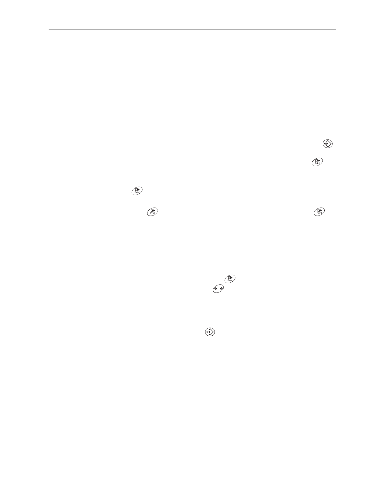
KboArd Keyboard test
PUSH 1 ... 25
• Press the keys in the following order:
If the key works, the scale changes to the next key.
Note
You cannot abort the keyboard test!
If you have selected the menu item KboArd, you must press all keys.
dISPLAY Display test: The scale displays all functioning segments
SNr Display of the serial number
SNr2 Display of the serial number of scale 2. This menu item only appears if an analog
second scale is connected.
LiSt Printout of a list of all menu settings
LiSt2 Printout of a list of all menu settings of scale 2. This menu item only appears if an
analog second scale is connected.
LiSt.M Printout of a list of all values and settings in the memory
T
112012 13
2321242225
14 15 16
17 18 19
1056 78 9
12 3 4
Page 47

Settings in the menuIND445
47User manual 22013194B 05/08
WOrK.tim Display of the operating time of the scale and the number of weighing operations
performed
timE
SHOW.tim
• Operating time in hours, e.g. 56 h
WEIGH
SHOW.WGH
• Number of weighing operations, e. g. 135
rESEt.AL Resetting all menu settings to the factory settings
SUrE? Confirmation inquiry
• Reset all menu settings to the factory settings with
• Do not reset the menu settings with
T
Page 48

IND445
48
Interface description
User manual 22013194B 05/08
5 Interface description
5.1 SICS interface commands
The terminal IND445 supports the command set MT-SICS (METTLER TOLEDO Stand-
ard Interface Command Set). With SICS commands, it is possible to configure, query
and operate the terminal from a PC. SICS commands are divided up into various levels.
5.1.1 Available SICS commands
In the case of Levels 0 and 1, these are commands which, if implemented, will
function identically with all METTLER TOLEDO scales or weighing terminals.
In addition there are also further interface commands which apply either to the entire
product series or to the particular application level. This and further information on the
MT-SICS command set may be found in the MT-SICS Manual (Order Number 22 011
459 or at www.mt.com) or be obtained by request from your METTLER TOLEDO
customer service representative.
Command Meaning
LEVEL 0 @ Reset the scale
I0 Inquiry of all available SICS commands
I1 Inquiry of SICS level and SICS versions
I2 Inquiry of scale data
I3 Inquiry of scale software version
I4 Inquiry of serial number
I6 Inquiry of weighing parameters
S Send stable weight value
SI Send weight value immediately
SIR Send weight value repeatedly
Z Zero the scale
ZI Zero immediately
LEVEL 1 D Write text into display
DW Weight display
K Keyboard check
SR Send and repeat stable weight value
TTare
TA Tare value
TAC Clear tare
TI Tare immediately
Page 49

Interface descriptionIND445
49User manual 22013194B 05/08
5.1.2 Requirements for communication between scale and PC
• The scale must be connected to the RS232, RS485, USB or Ethernet interface of a
PC with a suitable cable.
• The interface of the scale must be set to "Dialog" mode, see Section 4.6.1.
• A terminal progam must be available on the PC, e.g. HyperTerminal.
• The communication parameters baud rate and parity must be set in the terminal
program and on the scale to the same values, see Section 4.6.3.
5.1.3 Notes on network operation via the optional interface RS422/485
Up to 32 scales can be networked with the optional RS422/485 interface. In network
operation, the scales must be addressed from the computer before commands can be
sent and weighing results received.
Address Hex ASCII
00x300
10x311
20x322
... ... ...
90x399
10 0x3A :
11 0x3B ;
... ... ...
31 0x4F O
Description of the steps Host Direction Scale
1. Host addresses the scale, e.g. with the address
3A hex.
<ESC> : –––>
2. Host sends a SICS command, e.g. SI SI <CRLF> –––>
3. The scale confirms receipt of the command and
sends the address back
<––– <ESC>:
4. The scale responds to the command and returns
control of the bus to the host
<––– S_S____45.02_kg
<CRLF>
Page 50

IND445
50
Interface description
User manual 22013194B 05/08
5.2 TOLEDO Continuous mode
5.2.1 TOLEDO Continuous commands
In TOLEDO Continuous mode the scale supports the following input commands:
5.2.2 Output format in TOLEDO Continuous mode
Weight values are always transferred in TOLEDO Continuous mode in the following
format:
Command Meaning
P Printing out the current result
T Taring of the scale
Z Zero setting of the display
C Deleting of the current value
S Determining the reference
Status Field 1 Field 2
1 2 3 4 5 6 7 8 9 10 11 12 13 14 15 16 17 18
STXSWASWBSWCMSD – – – –LSDMSD – – – –LSDCRCHK
Field 1
Field 2
STX
SWA, SWB, SWC
MSD
LSD
CR
CHK
Cont-Wt: 6 digits for the weight value that is transferred without comma and unit
Cont-Wt: 6 digits for the tare weight that is transferred without comma and unit
ASCII character 02 hex, character for "start of text"
Status words A, B, C, see below
Most significant digit
Least significant digit
Carriage Return, ASCII character 0D hex
Checksum (2-complement of the binary sum of the 7 lower bits of all the characters sent
beforehand incl. STX and CR)
Page 51

Interface descriptionIND445
51User manual 22013194B 05/08
Status word A
Status bit
Function Selection 6 5 4 3 2 1 0
Decimal
position
X00 0 1 0 0 0
X0 0 0 1
X010
0.X 0 1 1
0.0X 1 0 0
0.00X 1 0 1
0.000X 1 1 0
0.0000X 1 1 1
Numerical
increment
X1 0 1
X2 1 0
X5 1 1
Status word B Status word C
Function/Value
Function/Value Bit kg/lb g t oz Bit
Gross/Net: Net = 1 0 0 1 0 1 0
Sign: Negative = 1 1 0 0 1 1 1
Overload/Underload = 1 2 0 0 0 0 2
Movement = 1 3 Print request = 1 3
lb/kg: kg = 1 4 Extended = 1 4
151 5
Power up = 1 6 Tare manually, only kg = 1 6
Page 52

IND445
52
Event and error messages
User manual 22013194B 05/08
6 Event and error messages
Error Cause Remedy
Display Dark
• Back lighting set too dark ➜ Set back lighting (b.LIGHt)
brighter
• No mains voltage ➜ Check mains
• Unit switched off ➜ Switch on unit
• Mains cable not plugged in ➜ Plug in mains plug
• Brief fault ➜ Switch device off and back on
again
Insufficient load
• Load plate not on the scale ➜ Place load plate on the scale
➜ Set to zero
• Weighing range not reached
Overload
• Weighing range exceeded ➜ Unload scale
➜ Reduce preload
• Result not yet stable ➜ If necessary adjust vibration
adapter or weigh dynamically
• Function not permissible ➜ Unload scale and set to zero
• Zeroing not possible with over-
load or insufficient load
➜ Unload scale
• Reference weight too low ➜ Select and place larger number of
reference parts on the scale
• No valid value from the reference
scale
➜ Check cable connection between
the units
➜ Check interface settings
• No calibration ➜ Unplug the mains plug then plug
it back in; switch unit off and then
back on in battery mode
➜ Calibrate scale
➜ Call METTLER TOLEDO Service
• Average piece weight too low ➜ Counting is not possible on this
scale with this average piece
weight
Page 53

Event and error messagesIND445
53User manual 22013194B 05/08
• Unstable weight value when
referencing
➜ Ensure stable surroundings
➜ Ensure that the weighing pan is
freely movable
➜ Adjust vibration adapter
• Impermissible target value or
impermissible tolerance
➜ Repeat input with permissible
values
• Setting the average piece weight
impermissible during weight
accumulating
➜ End weight accumulating
➜ Reset average piece weight
• Switching the weighing unit
impermissible during weight
accumulating
➜ End weight accumulating
➜ Switch weighing unit
• Printout not yet ended ➜ End printout
➜ Repeat required action
• Switching the weighing unit
impermissible during dynamic
weighing
➜ End dynamic weighing
➜ Switch weighing unit
• EAROM checksum error ➜ Unplug the mains plug then plug
it back in; switch unit off and then
back on in battery mode
➜ Call METTLER TOLEDO Service
Reference optimization not possible
• The total weight of the reference
parts exceeds 4 % of the scale
capacity
➜ Put on fewer reference parts
• No additional parts were put on
the scale for manual reference
optimization
➜ Put on reference parts for optimi-
zation
➜ Call METTLER TOLEDO Service
Weight display unstable
• Restless installation location ➜ Adjust vibration adapter
• Draft ➜ Avoid drafts
• Restless weighing sample ➜ Dynamic weighing
• Contact between weighing pan
and/or weighing sample and
surroundings
➜ Remedy contact
• Mains fault ➜ Check mains
Error Cause Remedy
Page 54

IND445
54
Event and error messages
User manual 22013194B 05/08
Incorrect weight display • Incorrect zeroing ➜ Unload scale, set to zero and
repeat weighing operation
• Incorrect tare value ➜ Clear tare
• Contact between weighing pan
and/or weighing sample and
surroundings
➜ Remedy contact
• Scale tilted ➜ Level scale
Error Cause Remedy
Page 55

Technical data and accessoriesIND445
55User manual 22013194B 05/08
7 Technical data and accessories
7.1 Technical data
7.1.1 General data
IND445
Applications
• Weighing
• Dynamic weighing
• Counting with fixed or variable reference quantity
• Counting with reference and bulk scale
• Accumulating
• Numerical definition of tare weights, average piece weights and reference quan-
tities
• 100 memory locations for tare weights, average piece weights, target weights
and target quantities
• Checkweighing and weighing-in to target weight/target quantity
Settings
• Resolution selectable
• Weighing unit selectable: g, kg, oz, lb, t
• Taring function: manual, automatic, chain tare
• Automatic zero point correction when the scale is switched on and during oper-
ation
• Filter for adapting to the ambient conditions (vibration adapter)
• Filter for adapting to the weighing type, e.g. dispensing (weighing process
adapter)
• Switch-off function, sleep mode for mains-operated devices, energy-saving
mode for battery operation
• Display lighting
• Handsfree mode for counting without touching any keys
• Add mode for determining the piece weight when counting
• Reference optimization
• Programmable memories and identifications
• Date and time
• Signal tone
• Graphic display of the weighing range
Display
• LCD (liquid crystal display), digits 0.83" (21 mm) high, with back lighting
Keypad
• Pressure point membrane keypad
• Scratch-proof labeling
Page 56

IND445
56
Technical data and accessories
User manual 22013194B 05/08
7.1.2 Dimensions
Housing
• Diecast aluminum housing
• Dimensions, see Page 56
Protection Class (IEC 529,
DIN 40050, EN60529)
• IP65 (not with Ethernet interface)
Mains connection Direct connection to the mains (MAINS supply voltage fluctuations up to ±10% of
the nominal voltage):
• 120 V, 60 Hz, 90 mA
• 100 V, 50/60 Hz, 90 mA
For battery operation:
• Connection via mains adapter: 90 – 264 V, 47 – 63 Hz, 300 mA
• Infeed on the unit: 24 V, 1.3 A
Battery operation If the voltage supply is interrupted, the unit automatically switches over to battery
operation
Ambient conditions
• Use
• Altitude
• Temperature
• Installation/overvoltage category
• Pollution degree
• Relative humidity
Indoor use only
up to 2000 m
–10 .. +40 °C / 14 .. 104 °F
II
2
Maximum relative humidity 80 % for
temperatures up to 31 °C / 88 °F,
decreasing linearly to 50 % relative
humidity at 40 °C / 104 °F
Interfaces
• 1 RS232 interface integrated
• 1 other optional interface possible
Resolution of the analog
second scale interface
• 300000 points in noncertified configuration
• 10000 points in certified configuration
Supply of the weighing cell
• 8.2 V
IND445
Dimensions in inch
2.80
1.93
7.87
10.91
1.42
0.17
Page 57

Technical data and accessoriesIND445
57User manual 22013194B 05/08
7.1.3 Net weights
7.1.4 Interface connections
The compact scale can be fitted with a maximum of 2 interfaces. The following combinations are possible:
7.1.5 Assignment of the interface connections
without battery with OptionPac
(incl. battery)
IND4.. 5.2 lb (2.4 kg) 9.6 lb (4.4 kg)
COM1 COM2 Note
RS232 –
RS232 RS232
RS485 RS232 COM1 can be optionally operated as RS422 or
RS485
RS232 Ethernet 10BaseT, RJ45
RS232 USB USB 1.1, Type B
RS232 Digital I/O 4 x in, 4 x out, D-Sub 9
RS232 Analog second scale
interface
Pin RS232
(COM1/
COM2)
RS422
(4-wire,
COM1)
RS485
(2-wire,
COM1)
Digital I/O
(COM2)
Analog
Interface
1 – – – GND + Excitation (+8.2 VDC)
2 TxD1/2 TxD1– TxD1–/RxD1– OUT0 + Sense
3 RxD1/2 RxD1– – OUT1 Shield
4 – – – OUT2 – Sense
5 GND GND GND OUT3 – Excitation (GND)
6– – – IN0 –
7 – TxD1+ TxD1+/RxD1+ IN1 + Signal
8 – RxD1+ – IN2 – Signal
9VCC VCC VCC IN3 –
Page 58

IND445
58
Technical data and accessories
User manual 22013194B 05/08
7.2 Accessories
Designation Order number
Protective cover for IND4.. 21 255 045
Wallmount for IND4.. 22 010 045
Second display RS-PD/PASM 21 302 875
Second display ADI412 22 013 978
Second display ADI412-B, with backlighting 22 013 977
Relay box 4 for connection to digital I/O interface 22 011 967
Connection cable for relay box 4, length approx. 1.5 m 21 254 225
RS232 cable for second scale, 39.37" (1.8 m) long 21 252 588
RS232 cable for PC, 39.37" (1.8 m) long 00 410 024
Page 59

AppendixIND445
59User manual 22013194B 05/08
8 Appendix
8.1 Safety checks
The terminal IND445 has been tested by accredited inspection bodies. It has passed
the safety checks listed below and carries the relevant test symbols. Production is subject to production monitoring by the inspection offices.
8.2 FCC
This equipment has been tested and found to comply with the limits for a Class A digital device, pursuant to both Part 15 of the FCC Rules and the radio interference regulations of the Canadian Department of Communications. These limits are designed to
provide a reasonable protection against harmful interference when the equipment is
operated in a commercial environment. This equipment generates, uses and can radiate radio frequency energy and, if not installed and used in accordance with the user
manual, may cause harmful interference to radio communications. Operation of this
equipment in a residential area is likely to cause harmful interference, in which case
the user will be required to correct the interference at his own expense.
Cet appareil a été testé et s’est avéré conforme aux limites prévues pour les appareils
numériques de class A et à la partie 15 des règlements FCC et à la réglementation des
radio-Interférences du Canadian Department of Communications. Ces limites sont
destinées à fournir une protection adéquate contre les interférences néfastes lorsque
l’appareil est utilisé dans un environnement commercial. Cet appareil génère, utilize
et peut radier une énergie à fréquence radioélectrique; il est en outre susceptible
d’engendrer des interférences avec les communications radio, s’il n’est pas installé et
utilisé conformément aux instructions du mode d’emploi. L’utilisation de cet appareil
dans les zones résidentielles peut causer interférences néfastes, auquel cas
l’exploitant sera amené à prendre les dispositions utiles pour palier aux interférence à
ses propres frais.
Country Test symbol Standard
Canada
USA
CAN/CSA-C22.2 No. 1010.1-92
UL Std. No. 61010A-1
Other countries CB Scheme
(no identification)
IEC/EN61010-1:2001
CUS
Page 60

Index
60 User manual 22013194B 05/08
IND445
9 Index
A
Accessories ............................ 58
Adjustment ............................. 34
Ambient conditions.................. 56
Applications ........................... 55
Auxiliary scale ........................ 27
Average ........................... 14, 39
Average piece weight ............... 23
C
Calibrate ................................ 34
Capacity utilisation .................. 13
Chain tare .............................. 13
Checkweighing ....................... 15
Configure memory................... 38
Continuous mode.................... 50
Counting parts ........................ 20
D
Dimensions ............................ 56
Display .................................... 7
Display accuracy .................... 34
Dynamic weighing ............ 14, 39
E
Error messages....................... 52
F
Filter ...................................... 35
H
Hands free ............................. 22
I
Identification ........................... 16
Info button.............................. 17
Interface protocol .................... 50
Interfaces
Configure ......................... 42
Connections ..................... 57
K
Keyboard ................................. 8
M
Mains connection ....................56
Memory .................................. 38
Menu
Application ........................ 36
Communication .................42
Diagnosis .........................46
Operation .......................... 28
Overview...........................30
Scale................................ 34
Terminal ........................... 40
Menu structure ........................ 29
Minimum accuracy ..................22
O
Operator guidance ................... 21
Operator menu ........................ 28
Options .............................. 6, 43
P
Password ...............................28
Power supply ............................9
Protocol.................................. 17
Q
Quantity scales........................ 27
R
Reference determination, automatic
23
Reference optimisation ............. 23
Reference quantity....................22
Reference scales...................... 26
Reset
Application ........................ 39
Interface............................ 43
Scale................................ 35
Terminal ........................... 41
RS422/RS485.........................49
S
Safety checks ..........................59
Settings ..................................55
SICS commands......................48
Supervisor menu .....................28
Switching off ...........................11
Switching on ...........................11
T
Tare
Automatic ......................... 12
Chain tare......................... 13
Clear................................ 12
Tare weight
Call up ............................. 13
call up ............................. 12
Clear................................ 13
Enter ................................ 12
Save ................................ 12
Target quantity ........................ 25
Target weight .......................... 15
Call up ............................. 15
Clear................................ 16
Save ................................ 15
Terminal settings ..................... 40
TOLEDO Continuous ................ 50
Totalising ............................... 18
Two scales ....................... 18, 26
W
Weighing unit ......................... 34
Weighing-in............................ 16
Weight ................................... 57
Z
Zeroing................................... 11
Page 61

Page 62

*22013194B*
22013194B
Subject to technical changes © Mettler-Toledo (Albstadt) GmbH 05/08 Printed in Germany 22013194B
Mettler-Toledo (Albstadt) GmbH
D-72458 Albstadt
Tel. ++49-7431-14 0, Fax ++49-7431-14 232
Internet: http://www.mt.com
 Loading...