

Mettler Toledo VIVA Service Manual
METTLER TOLEDO
VIVA Service Manual
Manual de Servicio ViVa
17179400A (05/09) 0.04
INTRODUCTION
This publication is provided solely as a guide for individuals who have purchased the
METTLER TOLEDO Viva scale product.
Information regarding METTLER TOLEDO Technical Training may be obtained by writing to:
METTLER TOLEDO
Scales & Systems
1900 Polaris Parkway
Columbus, Ohio 43240-2020
(614) 438-4511
©
Mettler-Toledo, Inc. 2004
No part of this manual may be reproduced or transmitted in any form or by any means,
electronic or mechanical, including photocopying and recording, for any purpose without
the express written permission of Mettler-Toledo, Inc.
U.S. Government Restricted Rights: This documentation is furnished with Restricted Rights.
METTLER TOLEDO RESERVES THE RIGHT TO MAKE REFINEMENTS
OR CHANGES WITHOUT NOTICE.
VIVA Service Manual
Precautions
A
READ this manual
BEFORE operating or
servicing this
equipment.
FOLLOW these
instructions carefully.
SAVE this manual for
future reference.
DO NOT allow
untrained personnel to
operate, clean, inspect,
maintain, service, or
tamper with this
equipment.
LWAYS
DISCONNECT this
equipment from the
power source before
cleaning or performing
maintenance.
WARNING
ONLY PERMIT QUALIFIED PERSONNEL TO
SERVICE THIS EQUIPMENT. EXERCISE
CARE WHEN MAKING CHECKS, TESTS AND
ADJUSTMENTS THAT MUST BE MADE WITH
POWER ON. FAILING TO OBSERVE THESE
PRECAUTIONS CAN RESULT IN BODILY
HARM.
WARNING
FOR CONTINUED PROTECTION AGAINST
SHOCK HAZARD CONNECT TO PROPERLY
GROUNDED OUTLET ONLY. DO NOT
REMOVE THE GROUND PRONG.
WARNING
DISCONNECT ALL POWER TO THIS UNIT
BEFORE REMOVING THE FUSE OR
SERVICING. FAILURE TO DO SO MAY
RESULT IN BODILY INJURY OR PROPERTY
DAMAGE.
CAUTION
BEFORE CONNECTING/DISCONNECTING ANY INTERNAL
ELECTRONIC COMPONENTS OR INTERCONNECTING WIRING
BETWEEN ELECTRONIC EQUIPMENT ALWAYS REMOVE POWER
AND WAIT AT LEAST THIRTY (30) SECONDS BEFORE ANY
CONNECTIONS OR DIS-CONNECTIONS ARE MADE. FAILURE TO
OBSERVE THESE PRECAUTIONS COULD RESULT IN DAMAGE TO
OR DESTRUCTION OF THE EQUIPMENT OR BODILY HARM.
CAUTION
OBSERVE PRECAUTIONS FOR HANDLING ELECTROSTATIC
SENSITIVE DEVICES.
VIVA Service Manual

Contents
1 INTRODUCTION......................................................................................................................................................................1
1.1 RELIABILITY .........................................................................................................................................................................1
1.2 STANDARD FEATURES...........................................................................................................................................................1
1.3 CONFIGURATION ...................................................................................................................................................................1
1.4 PHYSICAL DIMENSIONS.........................................................................................................................................................2
1.5 POWER REQUIREMENTS ........................................................................................................................................................3
1.6 TEMPERA TURE AND HUMIDITY .............................................................................................................................................3
1.7 WEIGHTS AND MEASURES APPROVAL...................................................................................................................................3
1.8 OPTION .................................................................................................................................................................................3
2 INSTALLATION........................................................................................................................................................................5
2.1 PRECAUTIONS .......................................................................................................................................................................5
2.2 CONTENTS OF PACKAGING....................................................................................................................................................5
2.3 SETUP ...................................................................................................................................................................................5
2.4 POWER UP SEQUENCE............................................................................................................................................................7
2.5 SEALING ...............................................................................................................................................................................7
3 SET -UP AND CALIBRA TION..................................................................................................................................................9
3.1 SERVICE SETUP MODE: ..........................................................................................................................................................9
3.2 MASTER SETUP MODE:..........................................................................................................................................................9
3.3 SET UP SOFT SWITCH AND DEFAULT TABLE ........................................................................................................................10
3.4 COUNTRY DEFAULTS...........................................................................................................................................................12
3.5 GEOCAL USA STATE LOCATION CODES............................................................................................................................14
3.6 CALIBRATION......................................................................................................................................................................16
4 OPERATING INSTRUCTIONS.............................................................................................................................................18
4.1 DISPLAYS ............................................................................................................................................................................18
4.2 KEYBOARD .........................................................................................................................................................................18
4.3 CURSORS ............................................................................................................................................................................18
4.4 OPERATIONS .......................................................................................................................................................................18
4.4.1 Weighing and Communication...................................................................................................................................18
4.4.2 Backlight function......................................................................................................................................................18
4.4.3 Re-zero Functions......................................................................................................................................................19
4.4.4 Tare Function.............................................................................................................................................................19
5 SERVICE AND MAINTENANCE .........................................................................................................................................20
5.1 CLEANING AND REGULAR MAINTENANCE..........................................................................................................................20
5.2 TROUBLESHOOTING ............................................................................................................................................................20
5.3 CONNECTION DIAGRAM......................................................................................................................................................21
5.4 COMMUNICATION CABLE....................................................................................................................................................22
5.5 PARTS AND DESCRIPTIONS ..................................................................................................................................................23
5.6 SP ARE PAR TS AND ACCESSORIES..........................................................................................................................................28
6 APPENDIX...............................................................................................................................................................................31
6.1 PROTOCOLS.........................................................................................................................................................................31
6.2 PROTOCOLS FOR PRICE COMPUTING...................................................................................................................................32
6.2.1 IP3 .............................................................................................................................................................................32
6.2.2 L2 Mettler-Toledo ......................................................................................................................................................34
6.2.3 Berkel.........................................................................................................................................................................36
6.2.4 Dialog 06................................................................................................................................................................... 38
6.2.5 Anker..........................................................................................................................................................................43
6.2.6 Dialog 02 / 04............................................................................................................................................................44
6.3 PROTOCOLS FOR WEIGHT ONLY..........................................................................................................................................47
6.3.1 8217 Mettler Toledo...................................................................................................................................................47
6.3.2 Berkel.........................................................................................................................................................................56
6.3.3 NCI POS....................................................................................................................................................................58
6.3.4 Epelsa ........................................................................................................................................................................62
6.3.5 CAS............................................................................................................................................................................64
6.3.6 ICL/Fujitsu.................................................................................................................................................................66
1 Introduction
N
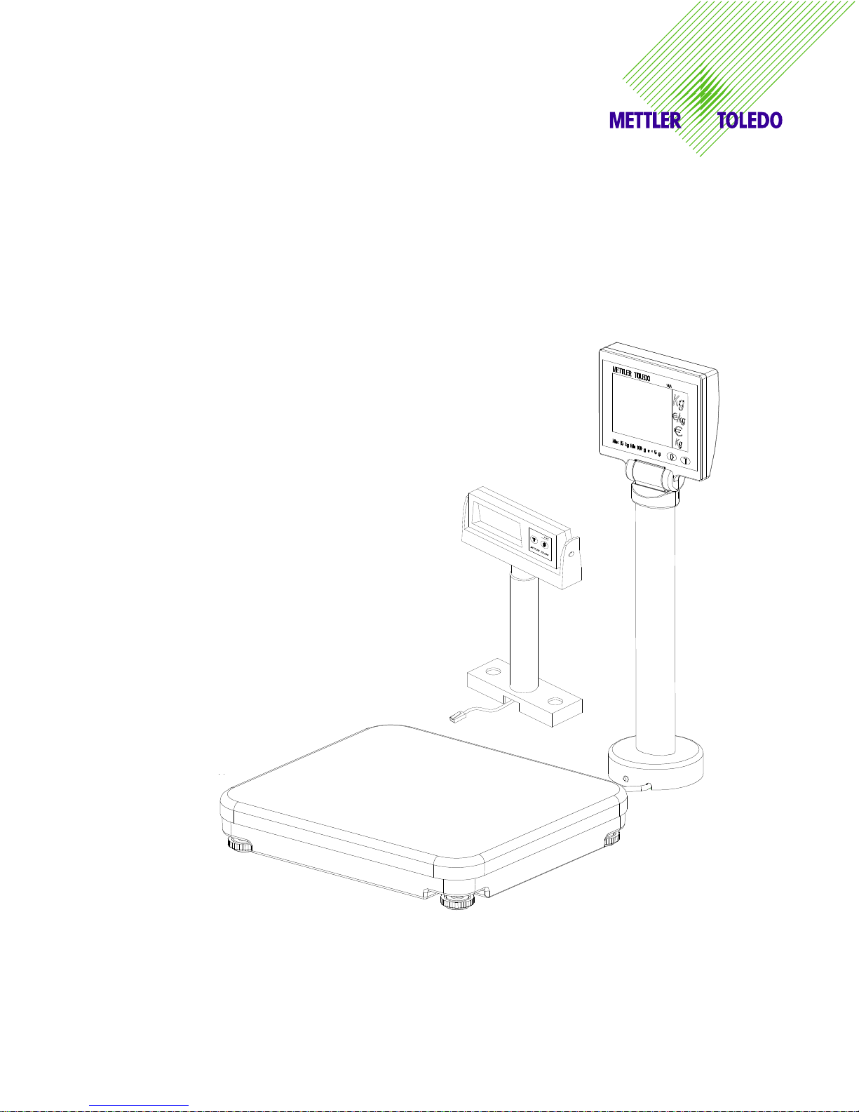
The VIVA is designed to connect with ECR and POS systems for weighing needs.
1.1 Reliability
The VIVA is developed, produced, and tested in a Mettler Toledo facility that has been audited and
registered according to international ISO 9001 quality standards and the ISO 14000 environment
control program.
1.2 Standard Features
Capacity: 6x0.002kg;15 x 0.005kg
15x0.005lb; 30x0.01lb
Platter: Stainless Steel: 280x316mm
Tower Display: LCD with backlight
LCD: 13.5mm high character weight (5 digits); unit price (6 digits); total price (6 digits).
Keyboard: two keys, with tactile and tone feedback when pressing the key.
Power supply: External 9VDC power supply.
A sealable Setup and Calibration Software switch
Basic functions: Zero; Tare
RS-232 interface
Base Mount Display (Weight Only with Rounded Platter)
1.3 Configuration
VIVA - X X X X -XXX
cccccccccccccccccccccccccc C
Application interface
CODE DESCRIPTION
Model name
0
1 RS232 WEIGH ONLY – 3 LINE DISPLAY
2 RS232 PRICE COMPUTING – 3 LINE DISPLAY
3 WEIGH ONLY, - SINGLE LINE DISPLAY
4 PRICE COMPUTING - 4 LINE DIPSPLAY
Display
CODE DESCRIPTION PART NUMBER
0 NONE
1 SINGLE (TOWER FOR ALL PRICE COMPUTING VERSIONS)
(TOWER FOR IN COUNTER WEIGH ONLY)
(TOWER/BASE FOR OTHER APPLICATIONS, WEIGH O
Platter: N/A
CODE DESCRIPTION
0 NONE
1 PLATTER SS ROUND CORNER
2 PLATTER SS SQUARE CORNER - 8217 FORM, IN COUNTER
Capacity
CODE DESCRIPTION
0 NONE
1 6KG/ 15 LB
2 15KG/ 30 LB
3
4
VIVA Service Manual 1
METTLER TOLEDO
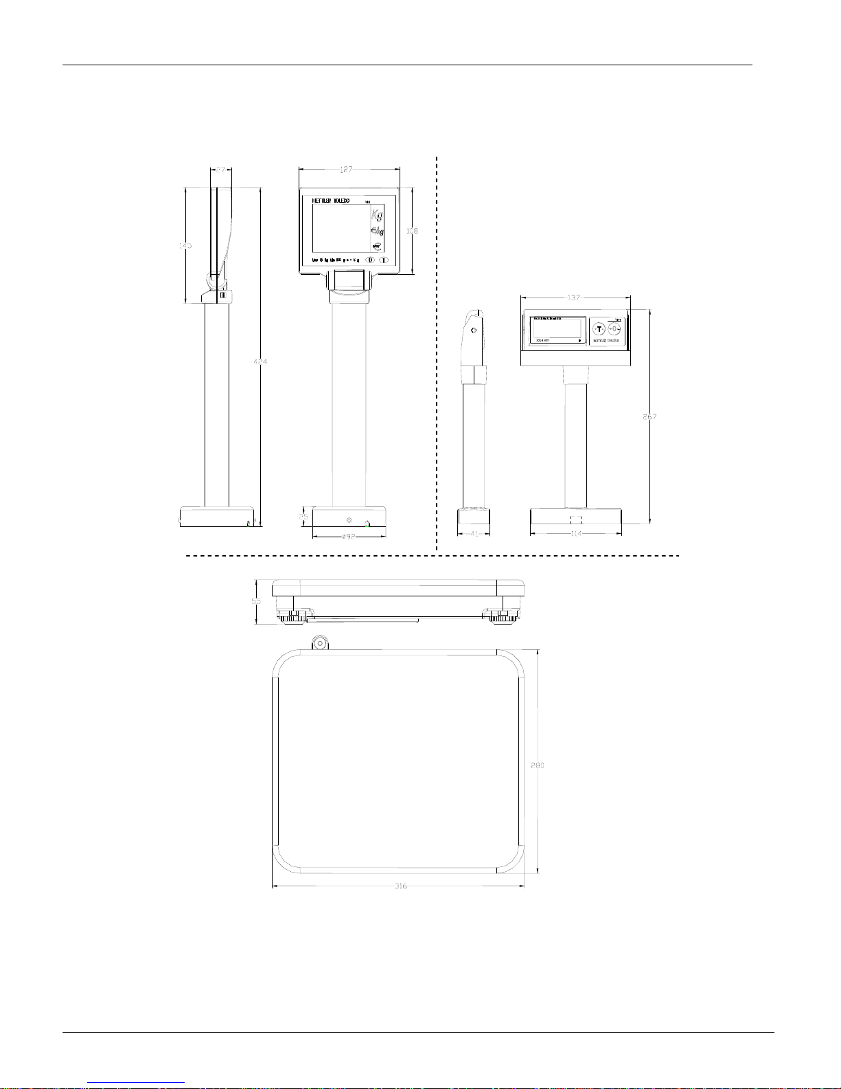
1.4 Physical Dimensions
The dimensions of the scale with tower is as follows:
The approximate shipping weight: gross weight of 5.6kg, net weight of 4.5kg.
The shipping carton dimensions: 445x390x160mm(L x W x H)
VIVA Service Manual
2
METTLER TOLEDO
1.5 Power Requirements
One external 9 VDC / 500 mA power supply provides power to the scale.
1.6 Temperature and Humidity
Working temperature range: -10 to +40 oC (+14 to +114F) at 10 to 85% humidity, non-condensing.
Storage temperature range: from -25 to +50
o
C at 10 to 85% humidity, non-condensing.
1.7 Weights and Measures Approval
OIML 3000e: OIML Certificate N
Type-approval certificate: T6294 EC
EC
NTEP: Certificate of Conformance Number 04-037
o
R76/1992-NL 1-03.21
1.8 Option
Remote display bracket
Dual Display (Weigh Only)
VIVA Service Manual
3

METTLER TOLEDO
Declaration of Conformity
Konformitätserklärung
Déclaration de conformité
Declaración de Conformidad
Conformiteitsverklaring
Dichiarazione di conformità
________________________________________________________________________________________________________________
We:
Wir:
Nous: Mettler-Toledo (ChangZhou) Scale & System Ltd.
Nosotros: 111 ChangXi Road,ChangZhou,JiangSu,213001,P.R.China.
noi:
wij:
declare under our sole responsibility that the product,
erklären, in alleiniger Verantwortung, daß dieses Produkt,
déclarons sous notre seule responsabilité que le produit,
declaramos, bajo nuestra sola responsabilidad, que el producto,
verklaren onder onze verantwoordelijkheid, dat het product,
dichiariamo sotto nostra unica responsabilitá, che il prodotto,
Model/Type: VIVA / RN20
To which this declaration relates , is in conformity with the following standard(s) or other normative document(s),
auf das sich diese Erklärung bezieht, mitder/den folgenden Norm(en) oder Richtlinie(n) übereinstimmt.
Auquel se réfère cette déclaration est conforme à la (aux) norme(s) ou au(x) document(s) normatif(s).
Al que se refiere esta declaración es conforme a la(s) norma(s) u otro(s) documento(s) normativo(s).
Waarnaar deze verklaring verwijst, aan de volende norm(en) of richtlijn(en) beantwoordt.
A cui si riferisce questa dichiarazione è conforme alla/e sequente/i norma/e o documento/i normativo/i.
EC marking EC Directive: Applicable Standards:
1) applies only to certified non-automatic weighing instruments.
betrifft nur zertifizierte nicht selbsttätige Waagen
s'applique uniquement aux instruments de pesage à fonctionnement non automatique approuvés
applicable solamente a strumenti di pesatura a funzionamento non automatico
Enkel van toepassing op gecertificeerde Niet Automatische Weegwerktuigen
aplicable solamente a instrumentos de pesaje aprobados de funcionamiento no automático
111 ChangXi Road,ChangZhou,JiangSu,213001,P.R.China ,June,2004, Mettler-Toledo (ChangZhou) Scale &System Ltd.
Yang JiaWu
Quality Assurance Manager
Important notice for verified weighing instruments in EC countries.
year
0103
The application of the Green M indicates that the non-automatic weighing instrument has been
verified at the place of manufacturer
73/23/EEC
Low Voltage Directive
89/336/EEC
EMC Directive
90/384/EEC
Non-automatic Weighing
Instruments Directive
EN60950-1:2001
EN61326-1:1997+A1:98
+A2:2001(Class B) ;
EN61000-3-2 :2000 ;
EN61000-3-3 :1995+A1 :2000
EN45501 1)
VIVA Service Manual
4
METTLER TOLEDO
A
2 Installation
2.1 Precautions
Before you install your VIVA scale, identify the best location for the equipment. The proper
environment enhances the operation and longevity of the scale. Keep in mind the following factors,
which might have a negative influence on the scale's operation:
Vibration diminishes the scale’s ability to measure accurately. Excessive vibration from
equipment such as conveyors can cause inaccurate and non-repeatable readings.
Be sure the scale is leveled properly.
Air currents can also diminish a scales performance. Avoid placing the scale in front of or
directly under air vents.
Other than items being weighed, keep the scale free from objects rubbing or pressing against
the platter.
2.2 Contents of Packaging
Package contents for all VIVA units include:
VIVA scale base
Stainless Steel Platter
AC-DC power adapter
Operation manual
Display Cable
Tower included and attachment hardware (The optional display may be packed separately)
Base Bracket (weigh only version with round corner platter)
2.3 Setup
1. Open the box, carefully remove the packing material, take all items out of the carton.
2. Attach the display as described below, depending on which version of scale you ordered:
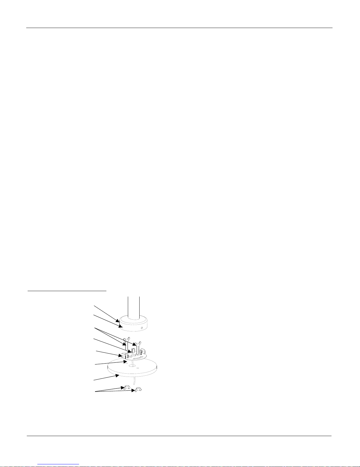
For Price Computing Version:
Tower base
Pin attachment holes
Attachment Screws (2)
Connector of cable
Attachment pins (2)
Tower Mounting Bracket
Table surface
ttachment wing nuts (2)
for Attachment Screws
A: Pull the connector of the cable through the holes of the table
surface and tower mounting bracket;
B: Put (2) screws though the (2) arch holes on the bracket and
(2) holes on the table surface;
C: Attach cover to the surface of table with (2) nuts.
D: Connect the cable to the connector at the bottom of the tower
display
E: Attach the base of the display to the mounting bracket by
insuring that the (2) pins on the bracket are inserted in the
holes of the base to attach the tower and snap the tower into
place.
VIVA Service Manual
5
METTLER TOLEDO
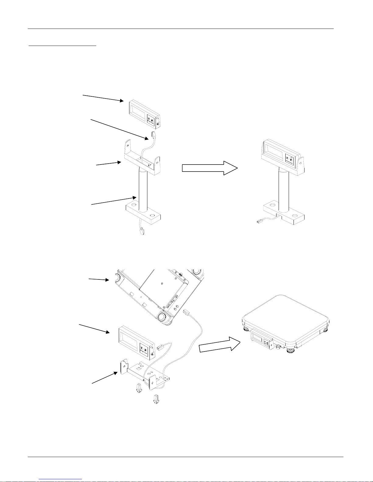
For Weigh Only Version:
The Weigh Only version comes with two different options for mounting the display, a tower mount or a base mount.
You can choose between the two and follow the illustrations below.
Assemble the Weight Only tower as is illustrated here:
Display
Display Cable
Display Bracket
Display Tower
Assemble the base mount as is illustrated here:
Bottom of
the Scale
Base
Display
Base
Mount
Bracket
VIVA Service Manual
6
METTLER TOLEDO
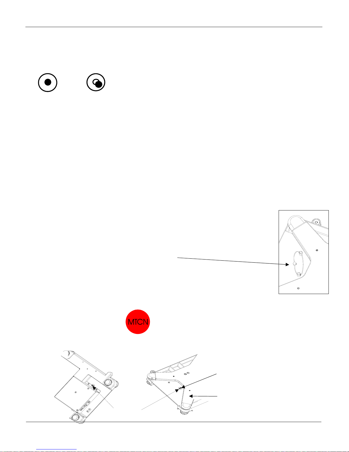
2. Set the scale base on a sturdy, level surface. Level the scale by turning the adjustable feet on the bottom of the unit.
Adjust the feet until the level bubble is in the center of the circle.
Bubble indicator:
Correct Wrong
3. Put the platter on top of the VIVA scale base.
4. Connect the tower display cable to the scale.
5. Connect the power cord from the wall transformer to the scale base.
2.4 Power up sequence
Plug the adapter into a properly grounded AC power outlet. The scale will go through a series of
self-tests and then will proceed to normal operating mode. The power-up sequence is as follows:
1. All segments of the display characters are lit. This verifies operation of all segments;
2. The scale displays the country code and GEO code, software part number and revision.
3. The scale then captures zero and is ready for normal operation.
Note: Before switching on the VIVA scale, always make sure there is nothing on the platter.
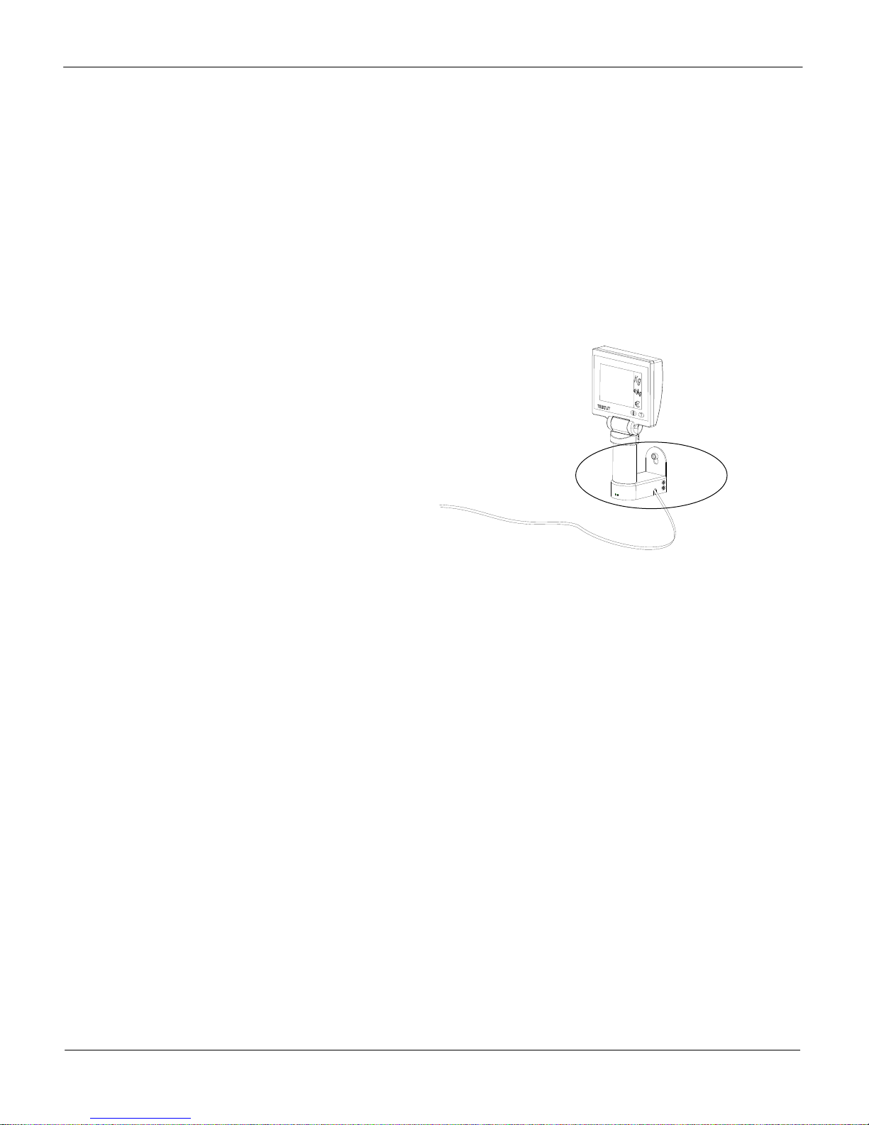
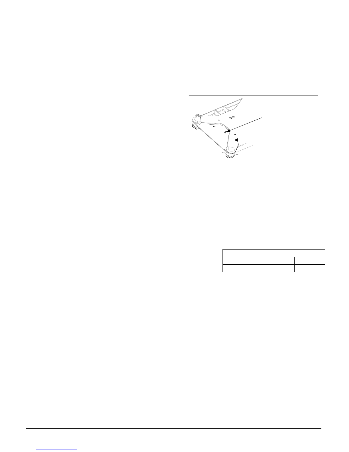
2.5 Sealing
After installation is complete, legal-for-trade applications require sealing the
enclosure so the settings cannot be changed.
There are two kinds of sealing: lead wire and label.
The lead wire sealing sequence is as follows:
Install special through-hole sealing screw.
Tighten these two screws and run a wire seal through the holes in the heads
of the screws.
Apply the seal.
The label sealing sequence
Security Sticker Ø 15mm, material Vinyl white 3690 E UL, color red, text color black.
There are two labels that used for sealing. The position for the sealing labels is shown below.
Location of
Calibration switch
Sticker Seal
VIVA Service Manual
Subplatter of scale
7

METTLER TOLEDO
For your notes:
VIVA Service Manual
8
METTLER TOLEDO
3 Set-up and Calibration
There are two types of setup modes. The first is called “Service Setup Mode” and it allows full
access to all soft switches and to calibrate the scale. The second is called “Master Setup Mode” and
it only allows access to soft switches that do not affect the metrology of the scale.
3.1 Service setup mode:
In order to access the Service Setup Mode insert a thin rod through the calibration hole and press the
button on the main PCB.
During the set up procedure, the display will start off by showing the following:
Display window
Weight
display
Price Computing Version Grp 1
Weigh Only Version Grp 1
After Pressing the Zero Key:
Display window
Weight
display
Price Computing Version Grp 1 Step 1 FR
Weigh Only Version 1.1 FR
Refer to Section 3.3 Setup and Soft Switch Default Table for all available settings.
Unit price
display
Unit price
display
Total price
display
Total price
display
3.2 Master setup mode:
This mode allows an operator to change certain softswitches directly from the keyboard. While turning
on the power, press and hold >0< key until “grP 1” is displayed. Refer to the Section 3.3 Set Up
Softswitch and Default Table for the accessibility of softswitches via keyboard.
The scale is configured for your specific needs with a special interactive set up procedure. In order to
access the various prompts, you must utilize the following keys during the scale setup mode.
>0<
>T<
VIVA Service Manual
This key is used to accept a group and then advance one softswitch at a time.
This key is used to step through the set up groups. Once a group is accepted, this
key is used to select the softswitch settings
9
METTLER TOLEDO
3.3 Set up Soft Switch and Default Table
Group.Step Function Possible Selections Master Mode Access
Group 1
DE (Germany)
FR (France)
US (USA)
AT (Austria and Croatia and Slovenia)
ES (Portugal and Spain)
BE (Belgium, Netherland, Poland and England)
IT (Italy)
1.1 Country Select
1.2 Initialize to Defaults
1.3 Beeper
1.4 Zero cursor
1.5 Decimal point
1.6*
1.7 Auto-clear of Tare
1.8 Weight unit
1.9
Group 2
2.1 Tare Enable
2.2 Chain Tare Enable
2.3*
2.4 Digital Filter Selection
2.5 GEO
2.6 Calibration
Decimal Position for
Price Displays
Expanded Weight
Display
Total Price Round
(To Nearest 0 or 5)
CH (Kazachstan and Switzerland)
UA (Ukraine)
RU (Russia)
HU (Hungary)
SK (Slovakia)
CZ (Czechia)
EJPORT (General export)
CN (China)
YES – Soft switches will be reset to factory defaults
NO – Soft switches will remain in current configuration
ON – Scale will “beep” when a key is pressed.
OFF – No sound is made when a key is pressed.
ON – Display zero cursor.
OFF – Disable zero cursor.
ON - ,
OFF - .
0 – Digits right of the decimal for Unit and Total Price fields.
1 – Digits right of the decimal for Unit and Total Price fields.
2 – Digits right of the decimal for Unit and Total Price fields.
3 – Digits right of the decimal for Unit and Total Price fields.
ON – Tare is automatically cleared when weight is removed.
OFF – Tare is not cleared when weight is removed.
Kg or lb
ON – Division quantity is displayed, Maximum is 30000.
OFF – Weight is displayed in normal display increments.
ON – Enables tare function.
OFF – Disables tare function.
ON – Enables multiple tares.
OFF – Only one tare per transaction is allowed.
ON – The total price will round up or down to 0 or 5.
OFF – Total price will not be rounded.
0 – Minimal
1 – Low
2 – Medium
3 – High
0 through 31 – See GeoCal chart below
No – Do not enter calibration mode
Yes – Calibrate scale
No
No
Yes
No
Yes
No
Yes
No
No
No
No
No
Yes
No
No
VIVA Service Manual
10
METTLER TOLEDO
Group.Step Function Possible Selections Master Mode Access
Group 3
0 – 1200
3.1 Baud rate
3.2 Parity
3.3 Data
3.4 Bit stop
3.5 Chose Protocol
Group 4***
4.1 Weight Change
4.2 Return to Zero
SAVE Save or abort setting
1 – 2400
2 – 4800
3 – 9600
0 – None
1 – Even
2 – Odd
0 – 7 data bit
1 – 8 data bit
0 – None
1 – 1 stop bit
2 – 2 stop bit
PCS Only
0 – IP3 Testut
1 – L2 Mettler-Toledo
2 – Berkel
3 – Anker
4 – Dialog 02 / 04
5 – Dialog 06
WO Only
6 – 8217 Mettler Toledo **
7 – Berkel
8 – NCI Weightronix
9 – Epelsa
10 – CAS
11 – ICL/Fujitsu
00 - No Weight Change Required
yy - 01 to 99 weight change divisions required
0 - No Return to Zero Required
1 - Return to Zero Active
SAVE – save all settings and return to weighing mode
ABORT – abort all settings and return to weighing mode
Yes
Yes
Yes
Yes
Yes
Yes
Yes
Yes
* Price Computing Version Only.
** When selecting the 8217 Protocol, press the enter key and the display will say “3.5 d n”. Press
“>T<” to change it to “3.5 d y”. Press “>0<” and then “Save” appears. This will setup the scale for
the default 8217 protocol. For customizing the 8217 protocol, please refer to section 6.3.1.
*** Group 4 not included in all versions of Viva software.
VIVA Service Manual
11
METTLER TOLEDO
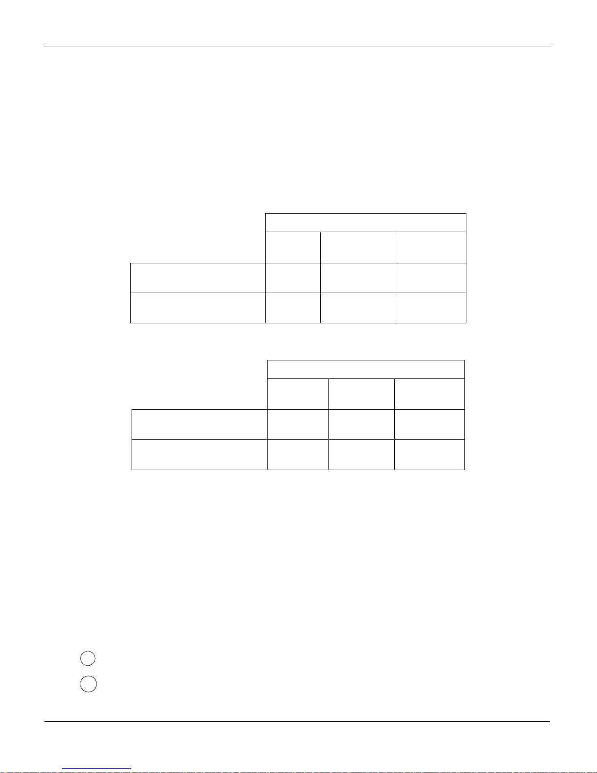
3.4 Country Defaults
PC WO PC WO WO
DE
(Germany) /
Group 1 Function
1.2 Initialize to Defaults No No No No No
1.3 Beeper On On On On On
1.4 Zero Cursor Off Off Off Off On
1.5 Decimal point On (,) On (,) On (,) On (,) Off (.)
1.6 Decimal Position for Price Displays 2 N/A 2 N/A N/A
1.7 Auto-clear of Tare On On On On On
1.8 Weight Unit Kg Kg Kg Kg Lb
1.9 Expanded Weight Display Off Off Off Off Off
Group 2
2.1 Tare Enable On On On On On
2.2 Chain Tare Enable On On On On Off
2.3 Total Price Round Off Off Off Off Off
Europe
1.1 Country Defaults
DE
(Germany) /
Europe
FR
(France)
FR
(France)
US
(USA)
2.4 Digital Filter Selection 1 1 1 1 1
2.5 GEO 20 20 19 19 15
2.6 Calibration No No No No No
Group 3
3.1 Baud rate 3 3 3 3 3
3.2 Parity 2 1 0 1
3.3 Data 0 0 1 0
3.4 Bit stop 1 1 1 1
3.5 Chose Protocol
Group 4*
4.1 Weight Change
4.2 Return to Zero
5 6 0 6 6
10 10 10 10 10
0 0 0 0 0
PC – Price Computing, WO – Weigh Only
*Group 4 not included in all versions of Viva software.
1
0
1
VIVA Service Manual
12
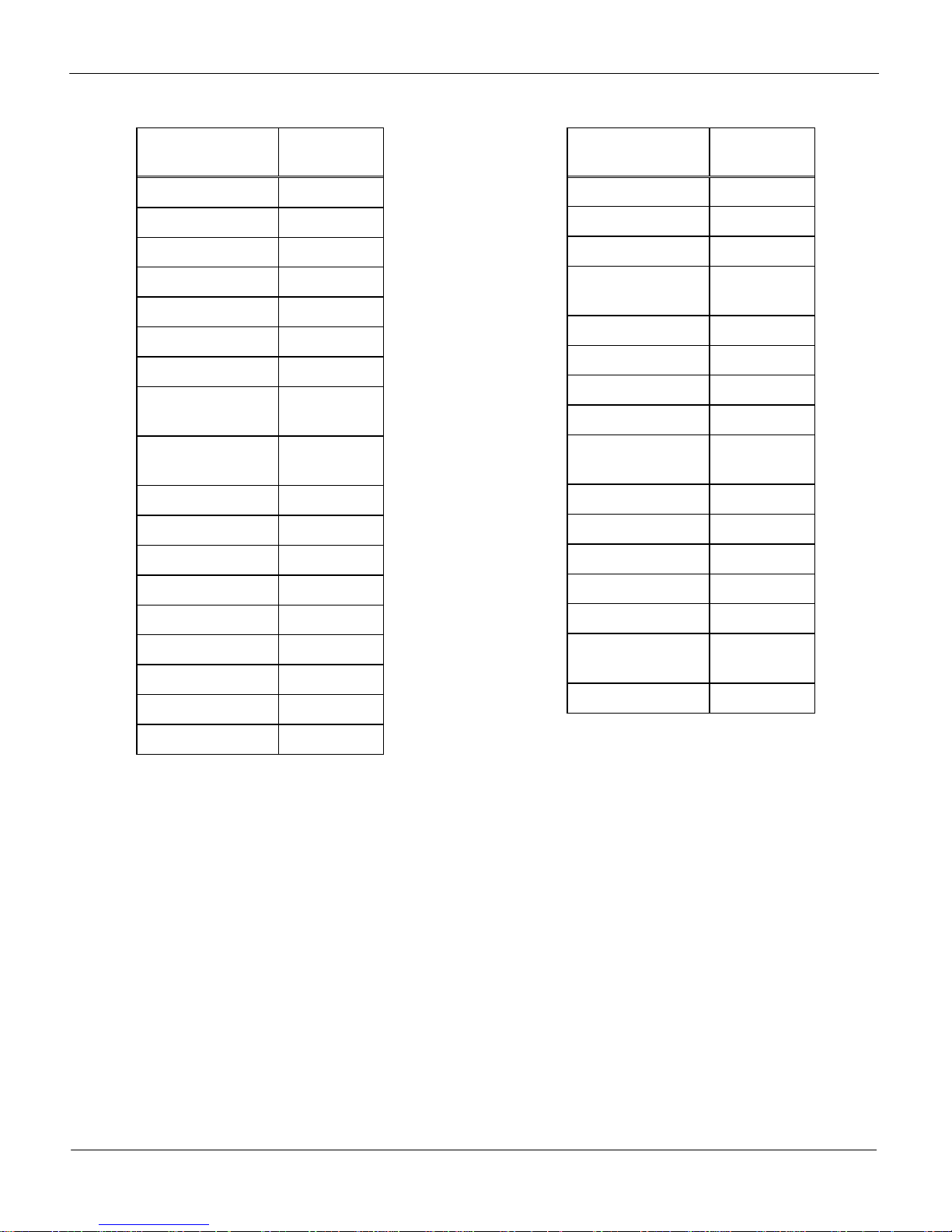
GeoCal Country Codes
METTLER TOLEDO
Country Geo-Value
Austria 18
Belgium 21
Bulgaria 16
Croatia 18
Czechia 20
Denmark 23
Estonia 24
Finland
France
25*
26
17
19*
Germany 20
Greece 15
Hungary 19
Ireland 22
Country Geo-Value
Liechtenstein 18
Lithuania 22
Netherlands 21
Norway
24*
26
Poland 21
Portugal 15
Romania 18
Russia 23
Sweden
24*
26
Switzerland 18
Slovakia 19
Slovenia 18
Spain 15
Iceland 26
Italy 17
Kazakhstan 18
Latvia 23
Turkey 16
United Kingdom
21*
23
Ukraine 21
* Factory Default
Luxemburg 20
VIVA Service Manual
13
METTLER TOLEDO
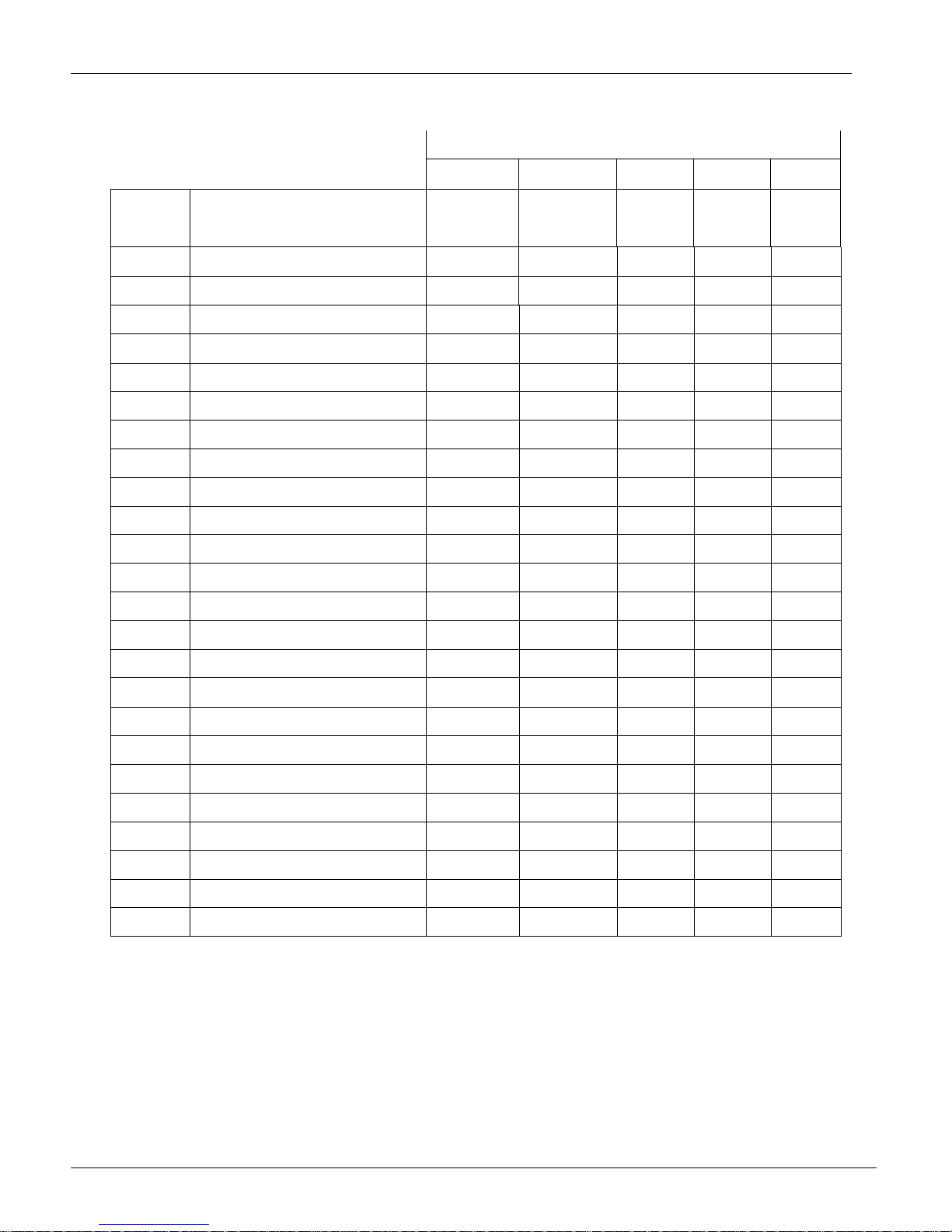
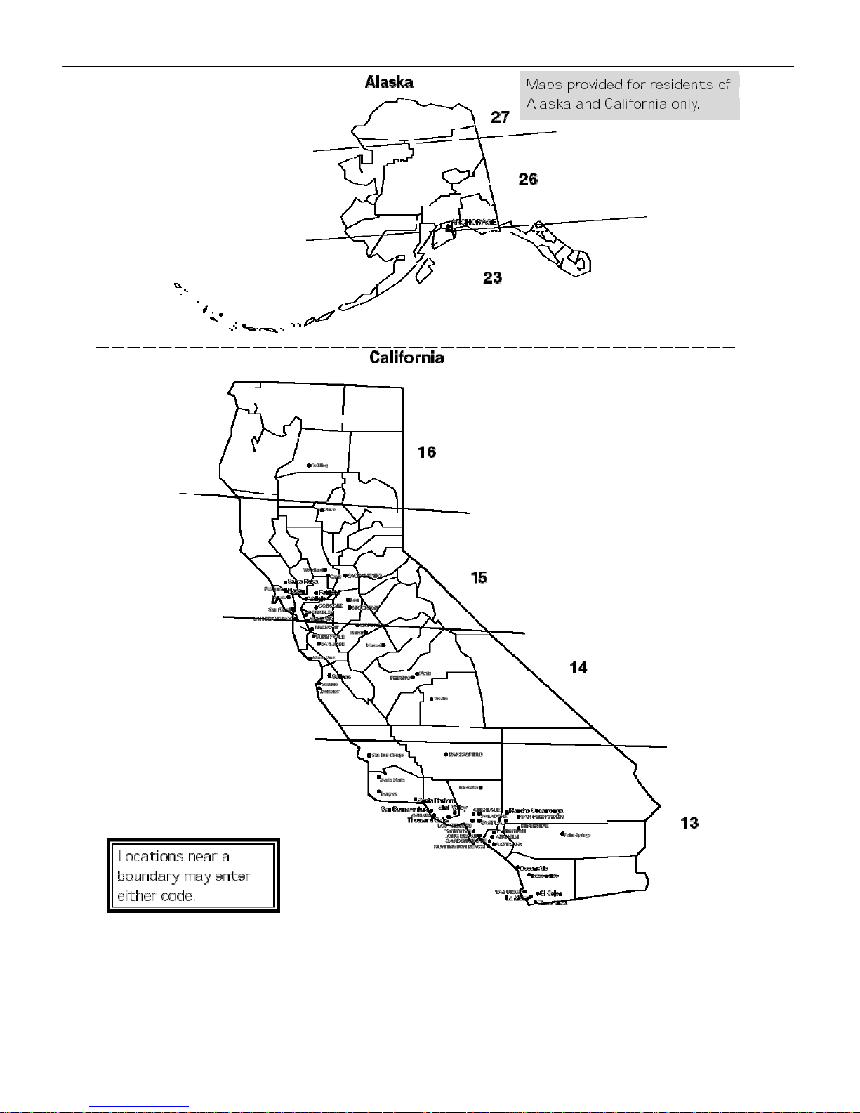
3.5 GeoCal
State Code
Alabama
Birmingham & North
South of Birmingham
Alaska
Arizona
Phoenix & North
South of Phoenix
Arkansas
California
Colorado
Denver & North
South of Denver
Connecticut
Delaware
Florida
West Palm Beach & North
South of West Palm Beach
Georgia
Hawaii
Idaho
North of Salmon River Mtns
South of Salmon River Mtns
Illinois
Bloomington & North
South of Bloomington
Indiana
North of Indianapolis
Indianapolis & South
Iowa
North of Des Moines
Des Moines & South
Kansas
Kentucky
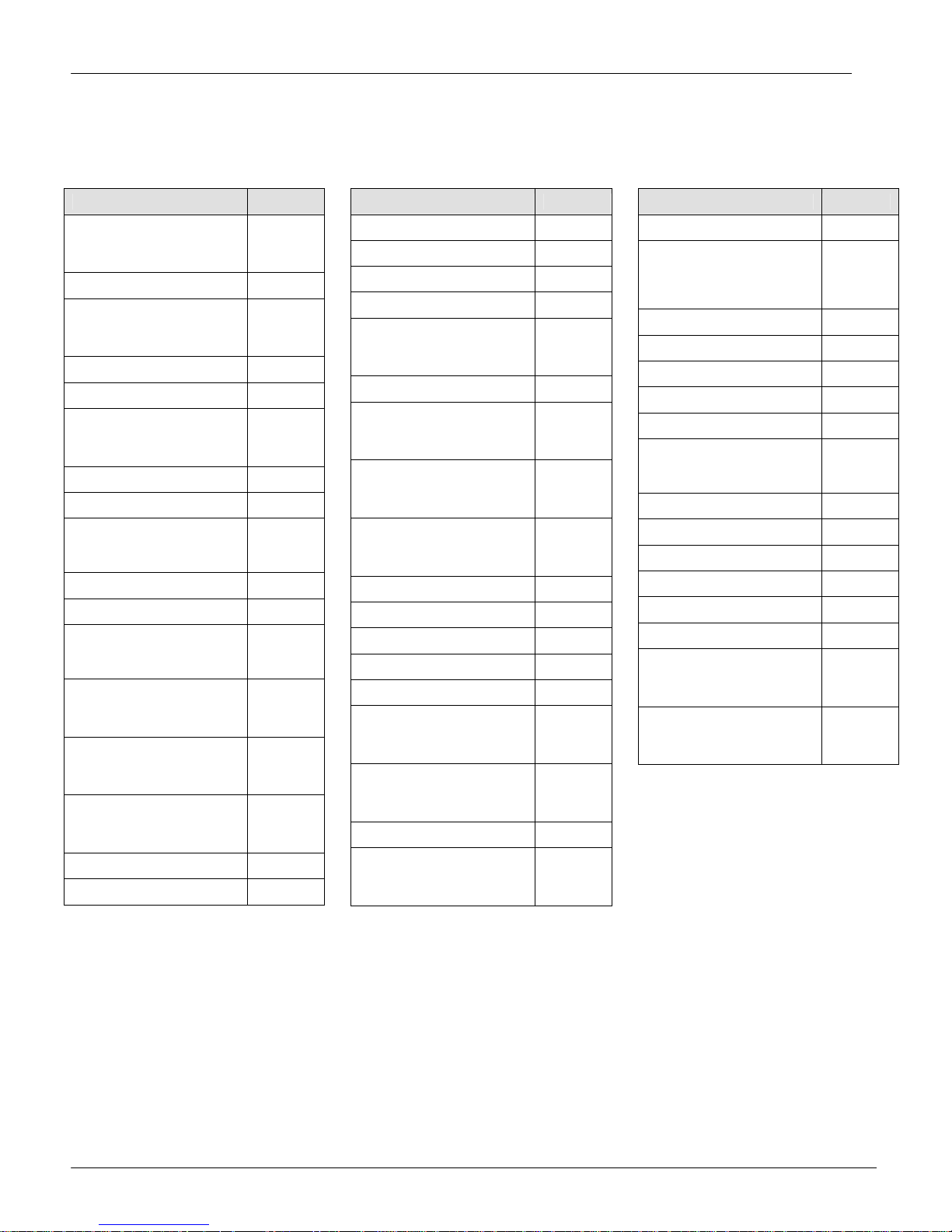
USA State Location Codes
State Code
Louisiana
Maine
Maryland
Massachusetts
Michigan
Northwest of Lake
Southeast of Lake
Minnesota
Mississippi
Kosciusko & North
South of Kosciusko
Missouri
North of Springfield
Springfield & South
Montana
Helena & North
South of Helena
Nebraska
Nevada
New Hampshire
New Jersey
New Mexico
New York
Albany & North
South of Albany
North Carolina
Raleigh & North
South of Raleigh
North Dakota
Ohio
Akron & North
South of Akron
13
12
See map
12
11
13
See map
13
12
16
15
11
10
12
9
17
16
16
15
16
15
17
16
14
14
12
18
15
17
18
17
18
13
12
15
14
18
17
15
13
17
16
11
17
16
14
13
18
16
15
State Code
Oklahoma
Oregon
Salem & North
Between Oakridge & Salem
South of Oakridge
Pennsylvania
Rhode Island
South Carolina
South Dakota
Tennessee
Texas
Northeast of Colorado River
Southwest of Colorado River
Utah
Vermont
Virginia
Washington, DC
Washington State
West Virginia
Wisconsin
Green Bay & North
South of Green Bay
Wyoming
North of Casper
Casper & South
13
18
17
16
16
16
13
17
13
12
11
13
17
14
15
18
15
18
17
15
14
VIVA Service Manual
14
METTLER TOLEDO
VIVA Service Manual
15
METTLER TOLEDO
f
3.6 Calibration
Note: These functions are directly related to the Weight & Measurement regulations in your
country, therefore they are protected by a sealed calibration button. The button is located as
shown below. For the scale to be usable in a legal for trade application, the button must be
sealed as is shown in section 2 after the calibration is complete.
To calibrate the scale, follow this sequence:
Note: Be sure that the scale has been placed
in an area free from air currents or excessive
Location o
Calibration switch
vibration. The platter should also be clean
from any debris and ready for use. Also, check
Sub-Platter of scale
to make sure the scale has been leveled
properly.
1. Press the calibration button
2. Go to Group 2 Step 6 of the Service Mode (WO scale will show “26 no” on the display).
3. Press the Tare key to change the prompt to “Yes”.
4. Press the Zero key to accept.
5. The display will briefly show “CAL” then show “Kg” or “Lb”, depending on how the scale was
setup originally.
6. Use the Tare key to select either “Kg” or “Lb”.
7. Press the Zero key to accept.
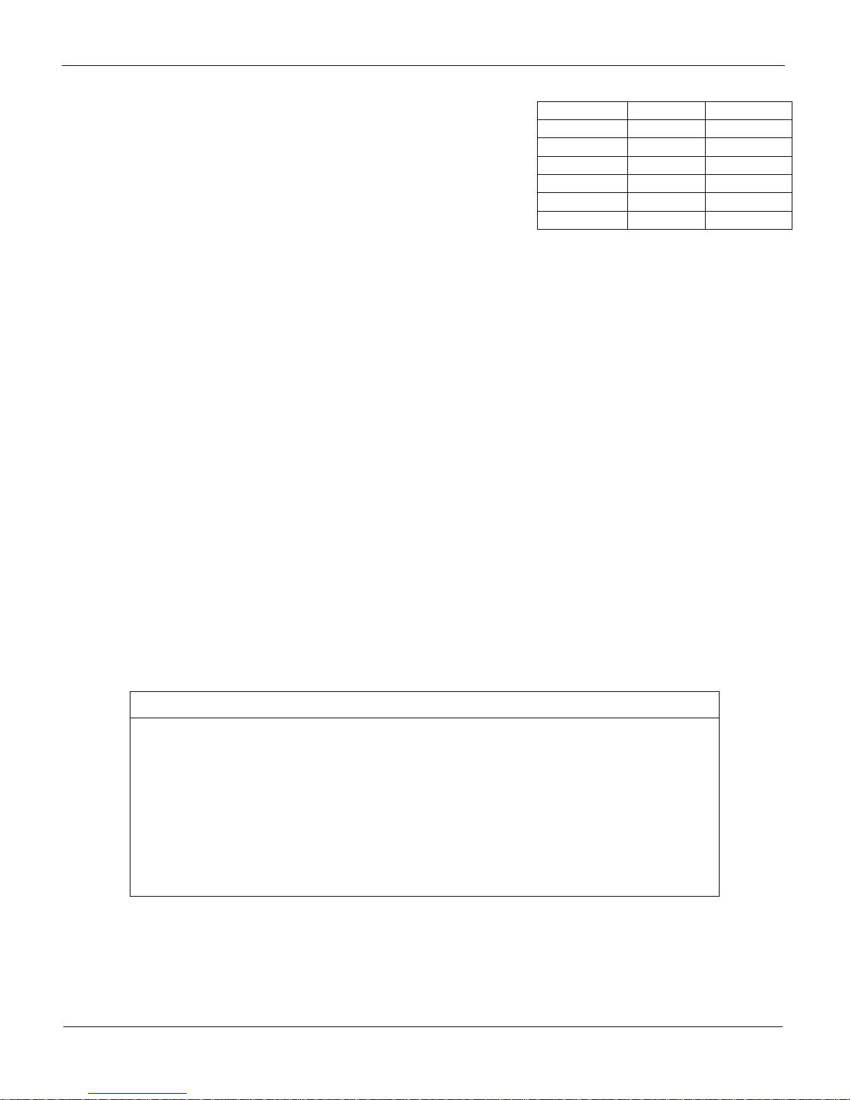
8. The display will now show “CAP” and then a number
corresponding to the Available Capacity chart shown
here. (i.e. CAP 6, for 6 kg)
Capacity (kg) 3 6 15 30
Capacity (lb) 6 15 30 60
Available Capacity
9. Use the Tare key to select the weight capacity.
Note: 30kg and 60lb are above the load cell’s capacity and will not work.
10. Press the Zero key to accept.
11. The display will now show “- - - - - -“. This indicates the scale is ready to take a zero reading.
Be sure the platter is on the scale and the platter has nothing on it or anything touching it.
12. Press the Zero key to accept.
13. The display will count down from 5 to 0.
Note: If the scale is unable to capture a stable reading it will start the count over at 5.
The count down will not restart until there is a stable reading. Verify nothing is
touching or interfering with the scale.
VIVA Service Manual
16
METTLER TOLEDO
14. The next step is to place weight on the scale. The
display will show a number that is illustrated in the chart
to the right and corresponds to the capacity that was
selected in Step 9. The display will start off showing
the 2/3 Load value. You can use the Tare key to
select the Full Load value. For instance, if you are
calibrating the scale for 15kg capacity, the scale would
display the 2/3 Load value of “10000”. This would
Capacity 2/3 Load Full Load
3kg 2000 3000
6kg 4000 6000
15kg 10000 15000
6lb 4000 6000
15lb 10000 15000
30lb 20000 30000
indicate to the scale you are going to use 2/3 of the capacity for the calibration. Place 10kg
on the scale and then press the Zero Key. If you selected “15000” to indicate full load, you
would place 15kg on the scale and then press the Zero Key.
15. The display will count down from 5 to 0.
Note: If the scale is unable to capture a stable reading it will start the count over at 5.
The count down will not restart until there is a stable reading. Verify nothing is
touching or interfering with the scale.
16. If the calibration is accepted, the display will show “GrP 3”. Press the Tare Key.
17. The display will show “Save”, press the Tare Key to select between “Save” and “Abort”.
18. Press the Zero Key to accept.
19. The scale will now save (or abort if you selected that in Step 17.) the calibration and cycle out
of the Service mode and return to normal weighing mode.
20. Verify the calibration was successful with the calibrated weight. If for some reason the
calibration was not successful, restart at Step 1.
21. If applicable, you should remove power from the scale and apply the appropriate calibration
seal.
22. Place the scale into service!
Calibration Quick Reference Chart
1. Break the calibration seal and press the Calibration button on the Main
PCB.
2. Select “Yes” in Group 2, Step 6 of the Service Mode.
3. Select “Kg” or “Lb”.
4. Select the Capacity.
5. Empty the scale and take the no load reading.
6. Select the desired weight, place it on the scale and take the reading.
7. Save the settings and verify the calibration in normal weighing mode.
VIVA Service Manual
17
METTLER TOLEDO
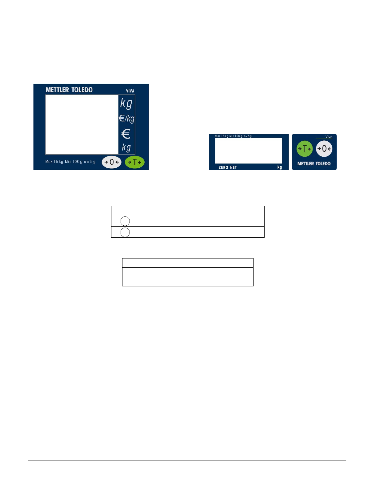
4 Operating Instructions
4.1 Displays
4.2 Keyboard
Key Description
>0<
>T<
Used to return the scale to gross zero.
4.3 Cursors
Cursor Description
ZERO When weight is gross zero.
NET When tare is entered.
4.4 Operations
4.4.1 Weighing and Communication
Place the item to be weighed on the platter, the weight will be displayed.
Remote ASCII commands can control the scale through the provided RS232 port. Commands
include zero, tare, and other data functions depending on the protocol. See Section 6 for
available protocols and their descriptions.
4.4.2 Backlight function
Tare key.
VIVA is equipped with a backlight for the display. If ambient lighting conditions are not sufficient,
the backlight can be switched on to easily read the display.
To activate, Press and hold the Zero Key until a long beep is heard and the backlight turns on.
Use the same procedure to switch the backlight off or just remove power to the scale.
VIVA Service Manual
18

When the scale is not used for 1 minute, the backlight will automatically switch off. When weight
is placed on the platter or a key is pressed, the backlight will switch on again.
4.4.3 Re-zero Functions
There are two ways to re-zero the scale:
Power-up Zero
The scale will automatically capture zero when it is turned on. The power-up zero capture range
is +/-10% of the scale capacity. When the scale is turned on with a weight on the platter of more
than +/-10% of the capacity, the scale will not capture zero and the weight display will show
"-----". After removing the weight, the scale will capture "zero".
Pushbutton Zero
The Zero Key re-zeros the scale within the range of +/-2% of the scale capacity. To use this
function, the scale must be in the gross weighing mode (NET cursor must be off) and in a no
motion condition. When the weight on the platter is more then +/-2% of the scale capacity,
pressing neither the Zero Key nor a remote ASCII Zero command will be accepted.
4.4.4 Tare Function
METTLER TOLEDO
The Tare Key allows you to subtract weight from the platter for items like containers that will be
used to hold the item being weighed.
Place the empty container or wrapping material on the platter.
Press the Tare Key.
Place the item to be weighed in the container or on the wrapping material and onto the platter.
VIVA Service Manual
19
METTLER TOLEDO
5 Service and Maintenance
This chapter provides information on servicing and maintaining the scale including:
Cleaning and regular maintenance
Troubleshooting
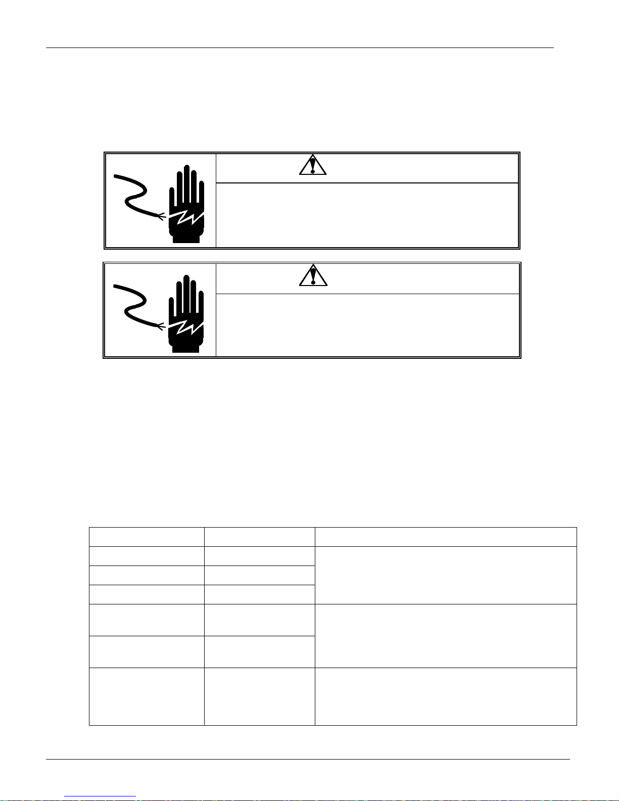
WARNING
ONLY PERMIT QUALIFIED PERSONNEL T O SERVICE
THIS EQUIPMENT. EXERCISE CARE WHEN MAKING
CHECKS, TESTS AND ADJUSTMENTS THAT MUST BE
MADE WITH POWER ON. FAILING TO OBSERVE
THESE PRECAUTIONS CAN RESULT IN BODILY HARM.
WARNING
DISCONNECT ALL POWER TO THIS UNIT BEFORE
SERVICING OR CLEANING.
5.1 Cleaning and Regular Maintenance
Do not use any types of industrial solvents. These may damage the display and platter finish. Wipe
the display area and weighing platter with a clean, soft cloth with water or a mild glass cleaner.
Regular maintenance inspections by a qualified service technician are also recommended.
5.2 Troubleshooting
The following table lists error messages, descriptions, and corrective actions.
Error Codes and Actions
Err 10 Transmission Error Reset Scale
E11 RAM error
E16 ROM error
E18 EEPROM error
Nnnnnn
in weight display
Nnnnnn
in total price display
Over capacity
Over 9999.99
Cycle power to the scale. For continued
problems call METTLER TOLEDO for replacement
Remove weight from Platter, if that does not work
try cycling the power to the scale. For continued
problems call METTLER TOLEDO for
replacement.
Uuuuuu
in weight display
VIVA Service Manual
20
Under zero
Place the platter on the scale. Either press the
Zero Key or cycle power to the scale. For
continued problems call METTLER TOLEDO for
replacement.
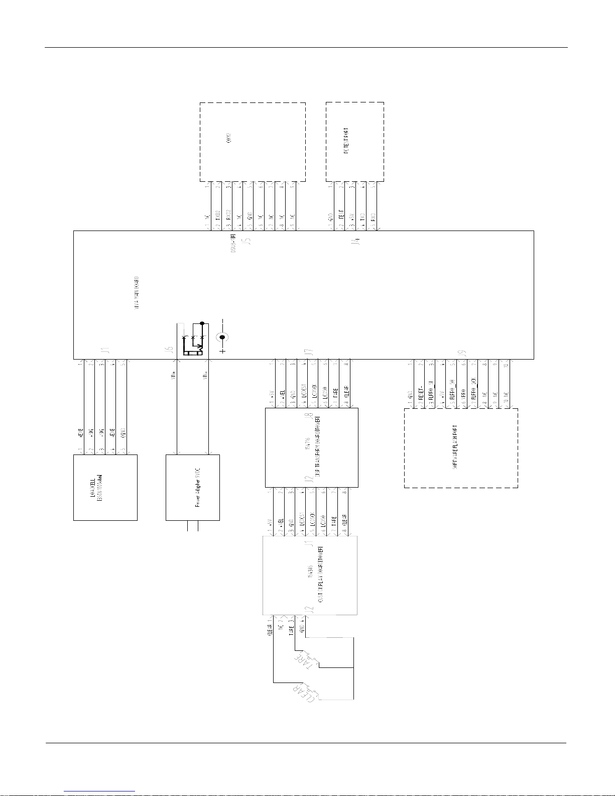
5.3 Connection Diagram
METTLER TOLEDO
VIVA Service Manual
21
METTLER TOLEDO
5.4 Communication Cable
A null modem cable is required when connecting the Viva to a PC or a standard RS-232 port.
PC DB9-M Viva DB9-F
Pin# Function Description Pin# Function Description
2 RxD Receive Data 2 TxD Transmit Data
3 TxD Transmit Data 3 RxD Receive Data
5 SGnd Signal Ground 5 SGnd Signal Ground
VIVA Service Manual
22
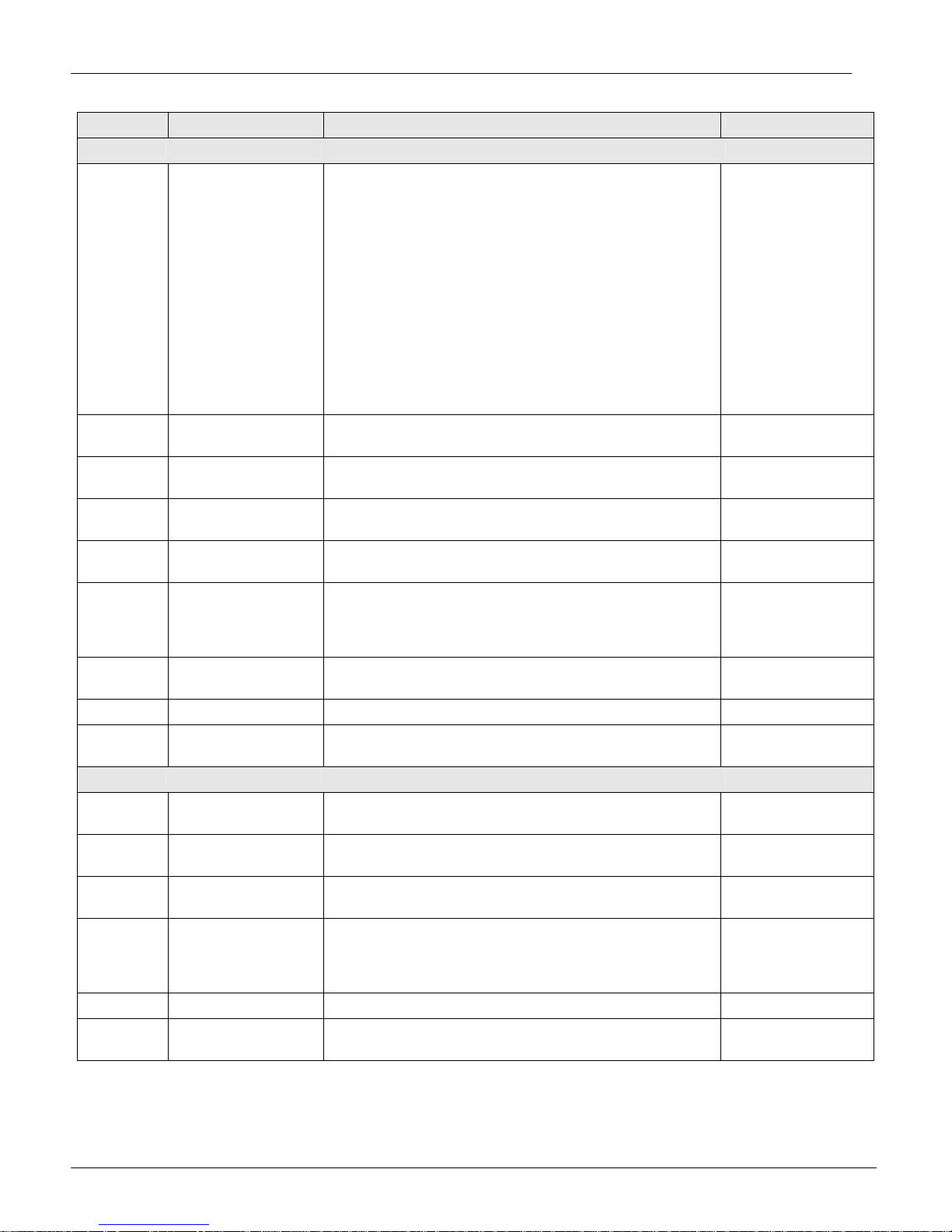
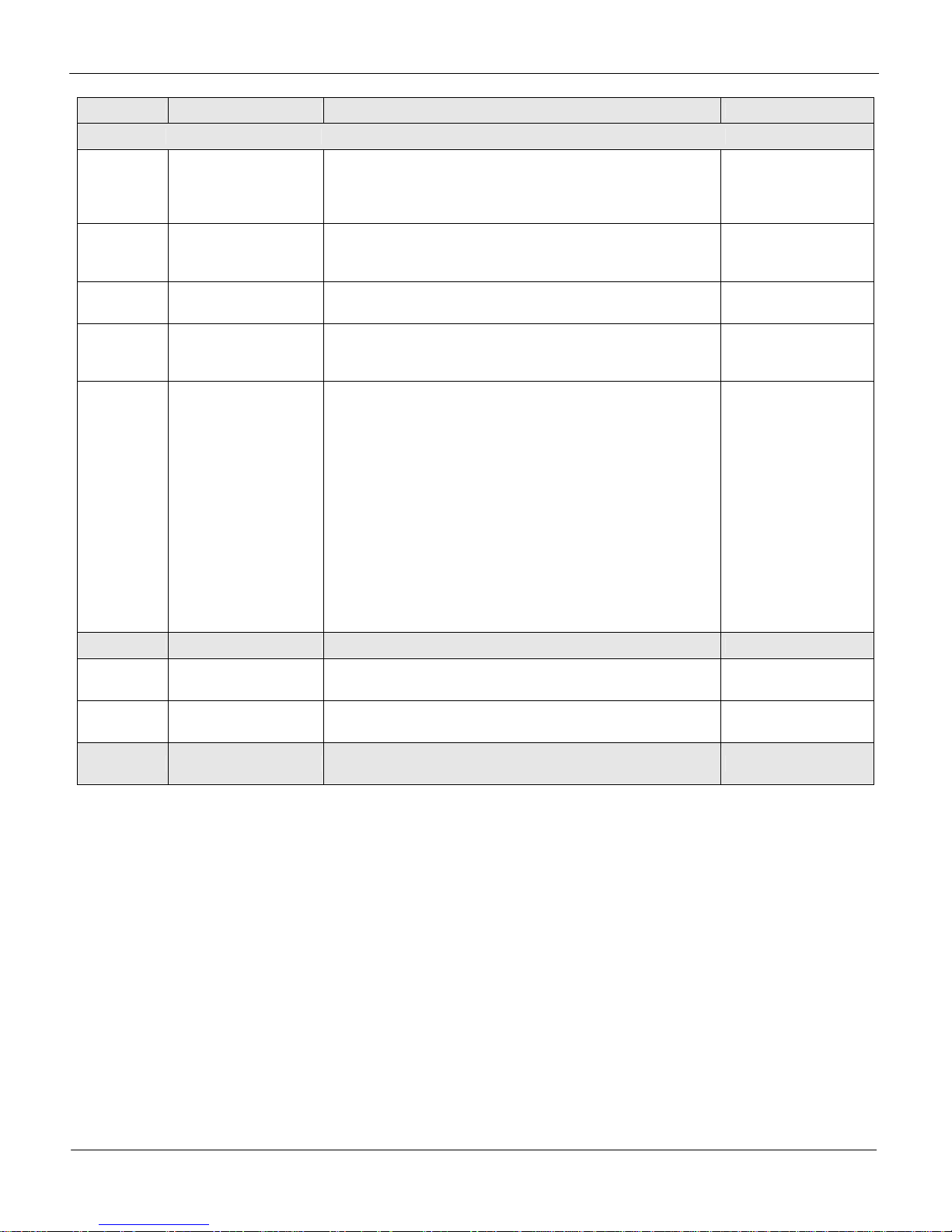
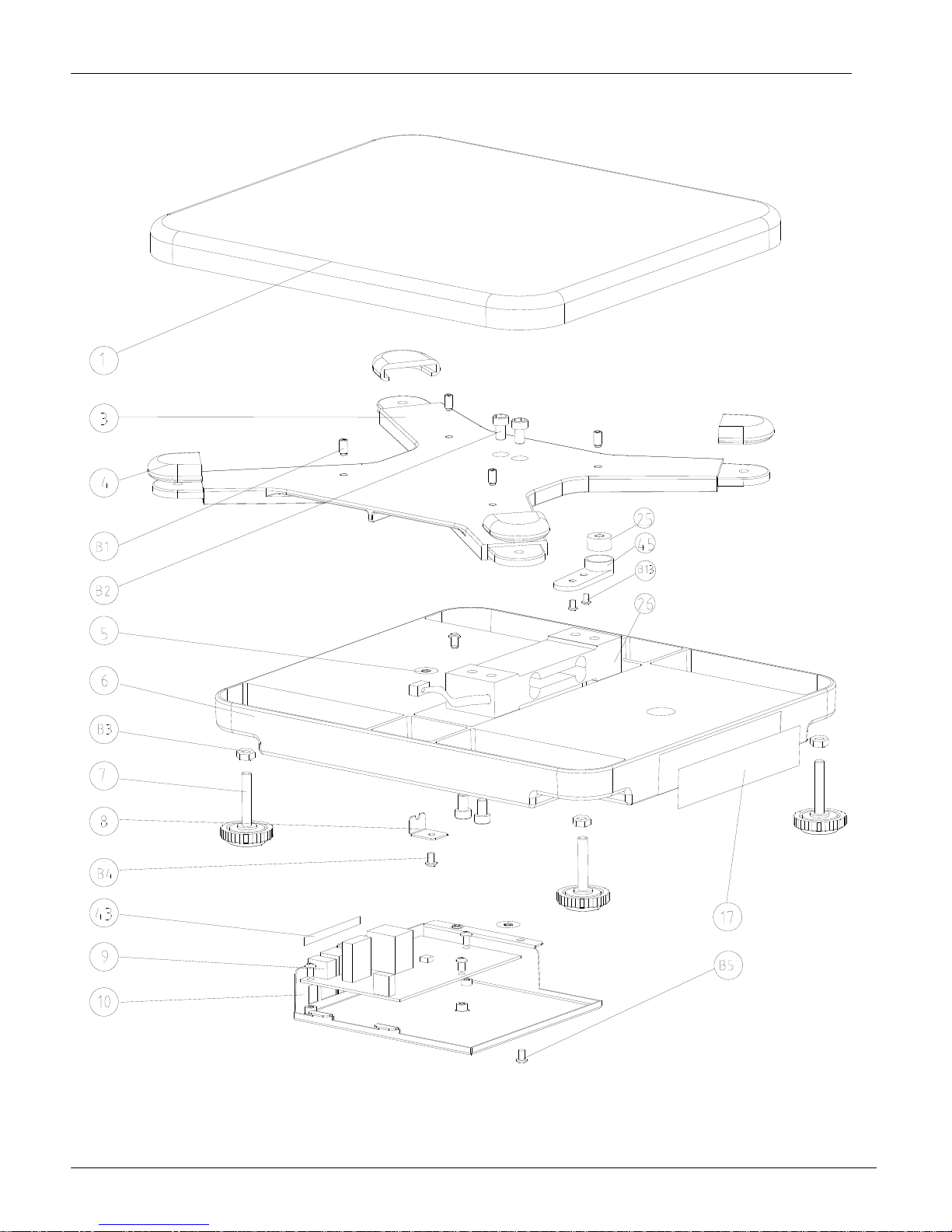
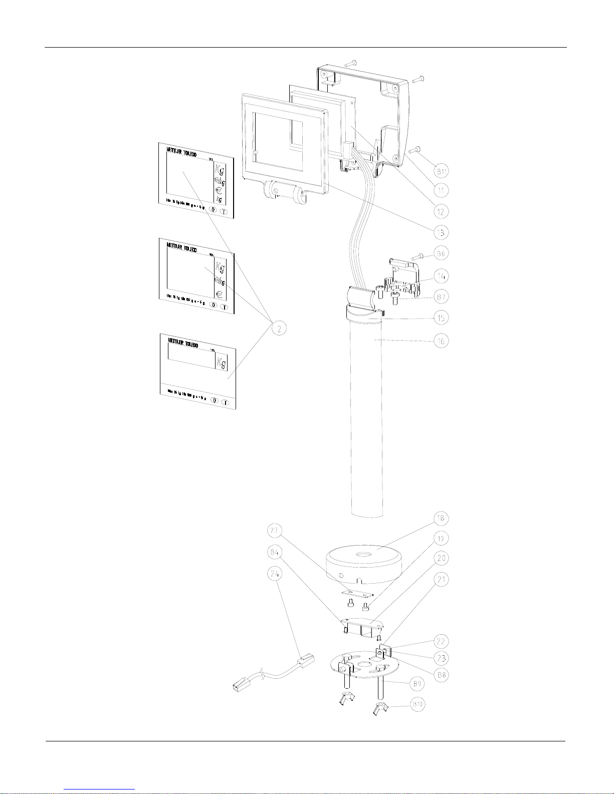
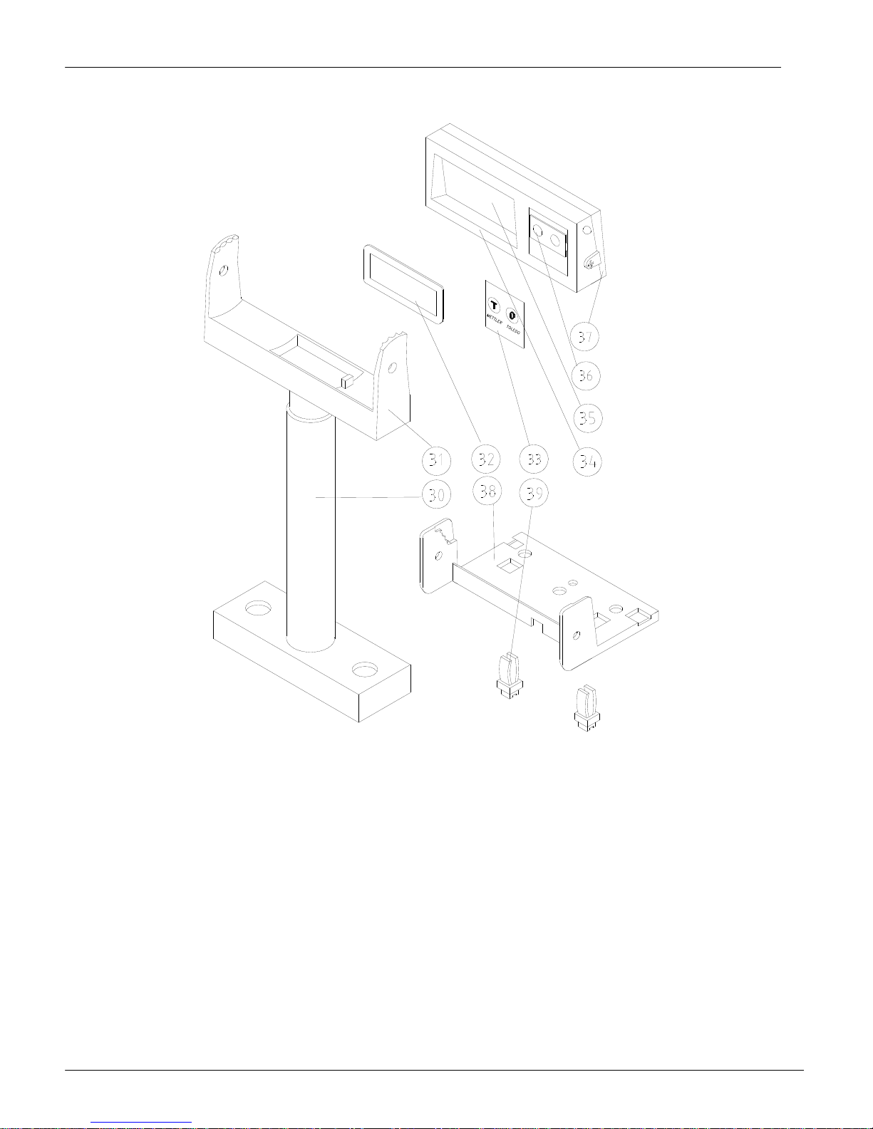
5.5 Parts and Descriptions
General Exploded Diagram.
Note: Most parts are not available for individual replacement. This following chart and
diagrams are only provided for reference.
ID Description Qty Option
1 PLATTER 1
2 OVERLAY 1
3 SPIDER 1
4 BUMPER, CORNER 4
5 STICKER, PAPER SEALING 2
6 BASE 1
7 FOOT 4
8 FIXING PLATE, LOADCELL CABLE 1
9 PCB ASSEMBLY, MAIN BOARD 1
10 BRACKET, MAIN PCB 1
11 BACK COVER 1
12 PCB ASSEMBLY, TOWER DISPLAY 1
13 FRONT COVER, DISPLAY 1
14 HALF CIRCLE HOOP. FIXING 1
15 HALF CIRCLE HOOP, COVER 1
16 TOWER 1
17 DATE PLATE(124X23.5) 1
18 TOWERBASE 1
19 M4X4 SEALING SCREW 4
20 PCB ASSEM . ADAPTER BOARD 1
21 TOWER BASE COVER 1
22 SPRING 2
23 PIN 2
24 HARNESS, FROM BASE TO DISPLAY 1
25 BUBBLE LEVER 1
26 AMI-15KG LOADCELL 1
27 FIXING PLATE CABLE 1
28 FIXING PLATE, CABLE 1 OPTION
29 BRACKET, BASE 1 OPTION
30 DISPLAY TOWER BASE 1
ID Description Qty Option
31 DISPLAY TOWER MOUNTING 1
32 LENS 1
33 KEYBOARD 1
34 DISPLAY FRONT COVER 1
35 DISLAY SUBASSEMBLY 1
36 FILM KEYBOARD 1
37 DISPLAY BACK COVER 1
38 DISPLAY BRACKET 1
39 BUCKLE 2
40 BUMPER A 2 OPTION
41 BUMPER B 2 OPTION
42 PLATTER 1 OPTION
43 INTERFACE LABEL 1
44 SHORT TOWER 1 OPTION
45 BUBBLE BASE 1
B1 SCREW M5X12 4
B2 SCREW M6X20 4
B3 NUT M6 4
B4 SCREW M4X6 7
B5 SCREW M4X8 1
B6 SCREW M2.9X19 1
B7 SCREW M5X10 4
B8 CIRCLIPS 3.2 2
B9 SCREW M6X45 2
B10 WING NUT M6 2
B11 SCREW M2.9X9.5 4
B12 SCREW M4X10-S.S 4 OPTION
B13 SCREW M3X12 2
METTLER TOLEDO
VIVA Service Manual
23
METTLER TOLEDO
VIVA Service Manual
24
METTLER TOLEDO
VIVA Service Manual
25
METTLER TOLEDO
VIVA Service Manual
26
 Loading...