

Mettler Toledo Viper M, Viper L, Viper D, Viper T, Viper RM Service Manual
...
Service Manual
METTLER TOLEDO
Viper M, L, D and T Scales
Viper RM, RL, RD and RT Terminals
On
Off
Zero
Tare
Sam
ple
Print
Sam
ple
Size
Scale
Clear
C
Info
Units
On
O
ff
Zero Tare Sample
P
rin
t
Sam
ple
Size
Scale
Info
U
nits
C
lear
C


General
About this service manual
Service concept
Product overview
1
2
Viper scales with small platform
Strain Gauge, IP65, MonoBloc, Ex
3
Viper scales with large platform
Strain Gauge, IP65, MonoBloc, Ex
4
5
Technician setup
6
Miscellaneous information
7
8
9
10
11
12
Exploded view drawings
Spare parts lists
Exploded view drawings
Spare parts lists
Accessing scale setup data
Entering scale setup data
Service Manual 21203788C Viper M, L, D and T Scales/Viper RM, RL, RD and RT Terminals
Technical data
Overview of weighing cells an preloads
Geographical table
Software
Software architecture
Error messages
Temperature compensation data
Repair of Viper scales
Repairs and replacement of components
Viper terminals
Exploded view drawings
Spare parts lists
Upgrade kits
Repair of Viper terminals
Repairs and replacement of components


Contents Page
1 How to use this service manual ........................................................................................................ 1-2
1.1 General ............................................................................................................................................ 1-2
1.2 Layout of the service manual .............................................................................................................. 1-2
1.3 Working with the service manual ........................................................................................................ 1-2
2 Service concept ............................................................................................................................... 1-3
3 Introducing the Viper scales product group ........................................................................................ 1-3
4 The Viper terminals .......................................................................................................................... 1-3
5 Safety.............................................................................................................................................. 1-4
6 Environmental protection .................................................................................................................. 1-4
Section 1
General

1-2 09/03 Service Manual 21203788C
Section 1 General Viper M, L, D and T Scales/Viper RM, RL, RD and RT Terminals
1 How to use this service manual
1.1 General
This service manual contains instructions for the repair and maintenance work to be performed by service engineers.
It is assumed that the reader is familiar with the operation of the scales and terminals, and can refer to the relevant operating
instructions when necessary.
1.2 Layout of the service manual
This manual comprises nine main sections:
• General: Section 1gives instructions on using the service manual, and also provides an overview of the Viper scales and
terminals covered by it.
• Viper scales with small platform: Section 2 contains the exploded view drawings and spare parts lists for Viper scales with
the small platform.
• Viper scales with large platform: Section 3 contains the exploded view drawings and spare parts lists for Viper scales with
the large platform.
• Viper terminals: Section 4 contains the exploded view drawings and spare parts lists for Viper terminals, as well as a list of
available upgrade kits.
• Repair of Viper scales: Section 5 describes all repair work and the replacement of components for Viper scales with large
and small platforms.
• Repair of Viper terminals: Section 6 describes all repair work and the replacement of components for Viper terminals.
• Technician setup: Section 7 describes how to enter scale data, calibrate the weighing system and use the diagnostic
functions.
• Miscellaneous information: Section 8 contains technical information on the Viper product group, plus an overview of all
load cells and preloads and a table of geographical adjustment values. In addition you will find instructions on connecting
weighing platforms to Viper terminals and information on appropriate load cells, as well as important information on
attaching a second weighing platform the the optional analog interface of Viper scales and terminals.
• Software: Section 9 contains information on the various software versions. It also describes typical error messages that can
appear following service work and provides troubleshooting instructions.
1.3 Working with the service manual
The section number and title are printed in the header of every page in the service manual. Each footer shows the order number
for the manual, the date issued and the page number.
The pages are numbered in the footer. First comes the section number, then a hyphen followed by the page number, starting with
1 in every section.
The exploded view drawings are provided as a guide for disassembly and assembly work and for identifying the order numbers
for spare parts.
When ordering spare parts, please use the information given in the spare parts lists. The item numbers in the first column
correspond to those on the exploded view drawing opposite.

Service Manual 21203788C 09/03 1-3
Viper M, L, D and T Scales/Viper RM, RL, RD and RT Terminals Section 1 General
2 Service concept
The scales have been designed so that defective components can be replaced with just a few simple tools. The LC-PT45 printer
for service is not required, as almost all parameters can be configured with the keyboard of the scale (in special cases
temperature compensation data of the MonoBloc load cell may need to be entered using a computer).
As you can see, we have kept it simple for efficient servicing.
3 Introducing the Viper scales product group
The Viper scales product group comprises the following models, which are all covered by this manual:
Viper M scales
Viper M scales possess basic weighing functions for simple weighing duties. Special versions of these scales are also available
(Viper EX M and Viper EX M MB) for use in explosion hazard zones (Class 1, Division 1) with the PSUx power supply unit or the
PSU power supply unit/interface.
Viper L scales
In addition to basic weighing functions, Viper L counting scales also have built-in functions for piece counting. An extended
keypad and a display with a visual weighing-in aid are available in order to use these additional functions.
Viper D scales
Viper D scales are counting scales providing an additional numeric keypad and ID functions.
Viper T scales
Viper T scales are the top-of-the-range models in the product group. These counting scales support a wide array of useful
functions. They have a dot matrix display with graphics capability and a numeric keypad. The various menu functions are
controlled by soft keys in the display, i.e. context-sensitive screen buttons which change according to the momentary status of
the menu. This scale type is also available for applications other than piece counting (such as SQC 16 and Remote).
Common features
Apart from the differences with regard to functions and operating and display elements, all models in the Viper product group
have the following common features:
– Depending on the weighing range, some models are only available with the small platform, some only with the large platform
and some with both. The essential difference between the two platform sizes is in their external dimensions and the type of
load cell used.
– All models are designed either for direct connection to the AC power line or contain a built-in rechargeable battery. Recharge-
able battery scales are connected to the AC power line via an AC adapter. Viper EX scales are powered by an external AC
adapter.
– All models are certifiable.
– The load cells are either of the strain gauge or MonoBloc type.
4 The Viper terminals
In terms of functionality and features the Viper RM, RL, RD and RT terminals exactly match the respective scale models (M, L, D
and T, see above). Using appropriate weighing platforms the Viper terminals allow to build customized weighing systems.
1-4 09/03 Service Manual 21203788C
Section 1 General Viper M, L, D and T Scales/Viper RM, RL, RD and RT Terminals
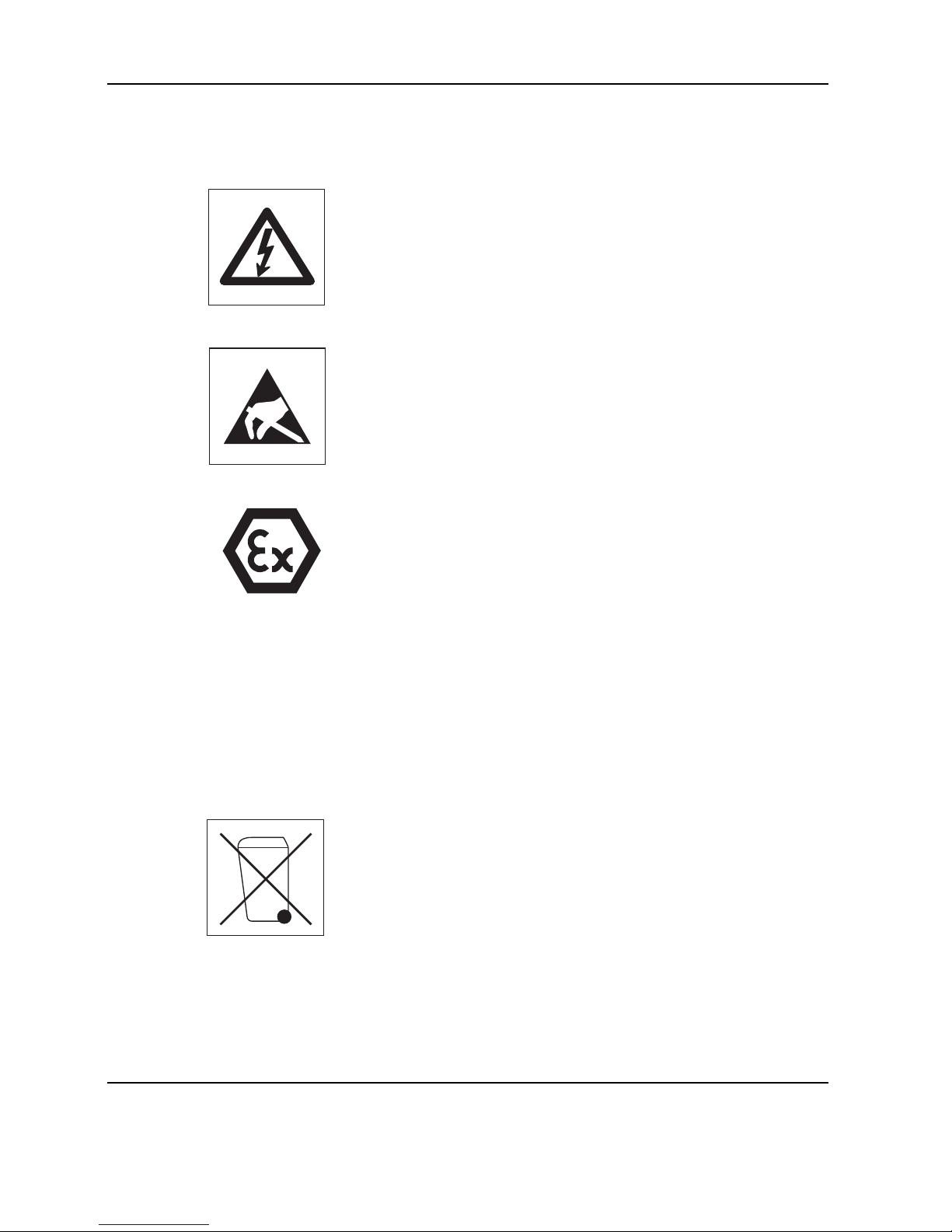
5 Safety
When carrying out service or repair work, always observe the following:
• Before opening the scale or terminal, isolate it from the AC power line (pull out the
plug).
• The scales and terminals contain precision electronic components that are
sensitive to electrostatic discharge. We recommend that you wear a grounding
wrist strap when doing any work in the interior of the scale or terminal, in order to
prevent any electrostatic charge building up. Grounding wrist straps are commercially available from electronic component suppliers.
• Servicing work in explosion hazard zones is strictly prohibited. Ignition power
could inadvertently be generated, causing an explosion. Servicing work should
therefore only be undertaken in secure areas. Please also observe all special
instructions in this Service Manual relating to work on Viper scales that are
approved for use in potentially explosive environments. Such instructions are
indicated by the adjacent symbol.
6 Environmental protection
Disposal of rechargeable batteries
Some models in the Viper product group have a built-in rechargeable battery. This
contains heavy metals which could be hazardous to the environment. The battery is
therefore classified as a hazardous waste, which must not be disposed of as normal
domestic refuse. Please ensure that used batteries are disposed of correctly in
accordance with the relevant local regulations.
Disposal of electronic components
Dispose of defective components in strict compliance with all local and national
regulations! In many countries electronic components are classified as hazardous
waste for whose disposal there are special regulations. In some countries electronic
components are collected separately for recycling. If necessary, find out the applicable regulations from the local authorities!

Contents Page
1 Scales ............................................................................................................................................. 2-2
1.1 Scales with strain gauge load cells (not including Ex version) ................................................................ 2-2
1.2 Scales with strain gauge load cells and IP65 protection......................................................................... 2-8
1.3 Scales with strain gauge load cells, Ex version ..................................................................................... 2-12
1.4 Scales with MonoBloc load cells (not including Ex version) ................................................................... 2-16
1.5 Scales with MonoBloc load cells, Ex version ........................................................................................ 2-20
2 Display units.................................................................................................................................... 2-24
2.1 Viper M display unit (not including Ex version) ..................................................................................... 2-24
2.2 Viper EX M display unit ...................................................................................................................... 2-26
2.3 Viper L display unit ............................................................................................................................ 2-28
2.4 Viper D display unit ........................................................................................................................... 2-30
2.5 Viper T display unit ............................................................................................................................ 2-32
3 Fasteners set ................................................................................................................................... 2-34
Repair: see Section 5
Section 2
Viper scales with small platform
2-2 09/03 Service Manual 21203788C
Section 2 Viper scales with small platform Viper M, L, D and T Scales/Viper RM, RL, RD and RT Terminals
1 Scales
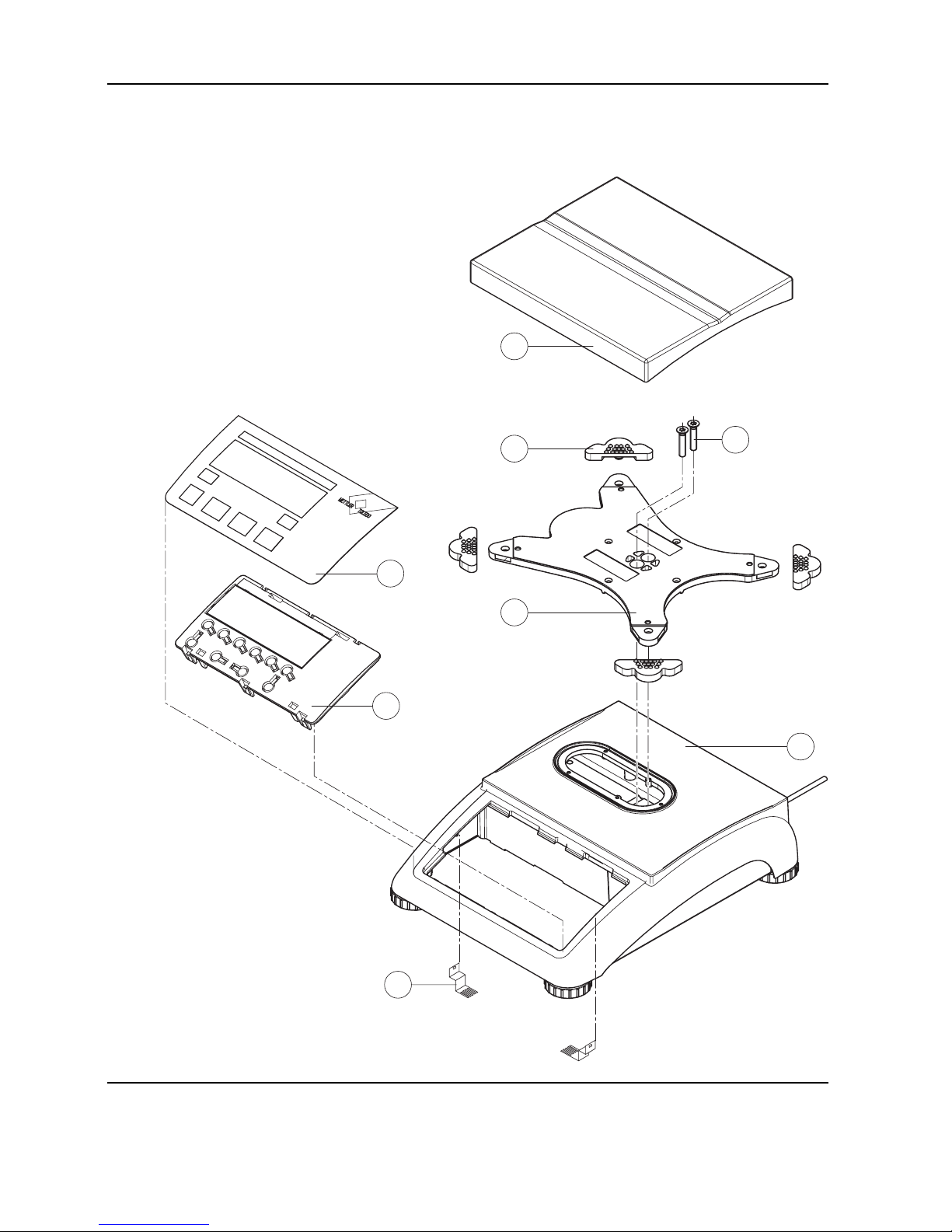
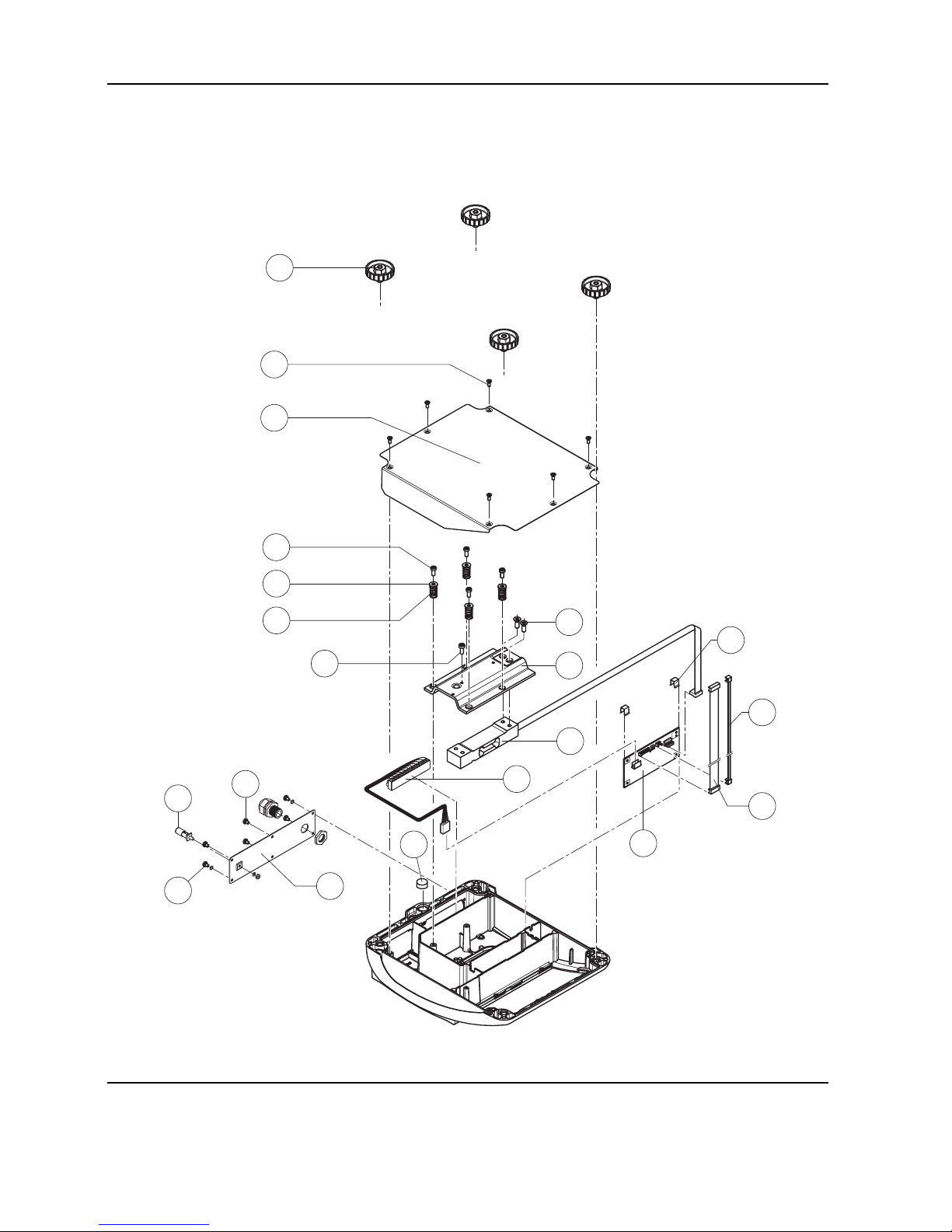
1.1 Scales with strain gauge load cells (not including Ex version)
2
3
4
1
6
7
5
8

Service Manual 21203788C 09/03 2-3
Viper M, L, D and T Scales/Viper RM, RL, RD and RT Terminals Section 2 Viper scales with small platform
Item Quantity Description Order No.
1 1 platter 7.9" x 9.5" (200 x 240mm) 21203071
2 4 rubber cushion (1 piece)
1)
21203073
3 2 countersunk Torx screw M6 x 30 *
4 1 pan support plate 7.9" x 9.5" (200 x 240mm) –
5 1 housing, VIPER with small platform –
6 1 keypad overlay Chapter 2
7 1 mounting plate and display unit (digital PCB with LCD and back-light unit) Chapter 2
8 2 EMC clamp 21203480
* included in the fasteners set (chapter 3)
– not available as spare part
1)
New rubber cushions have a hole in the surface to assist with assembly. A pin can be used to insert the cushion into the
corresponding drilled hole in the pan support plate. Earlier rubber cushions did not have this assembly aid.
2-4 09/03 Service Manual 21203788C
Section 2 Viper scales with small platform Viper M, L, D and T Scales/Viper RM, RL, RD and RT Terminals
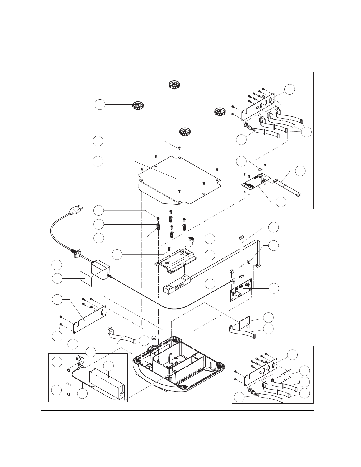
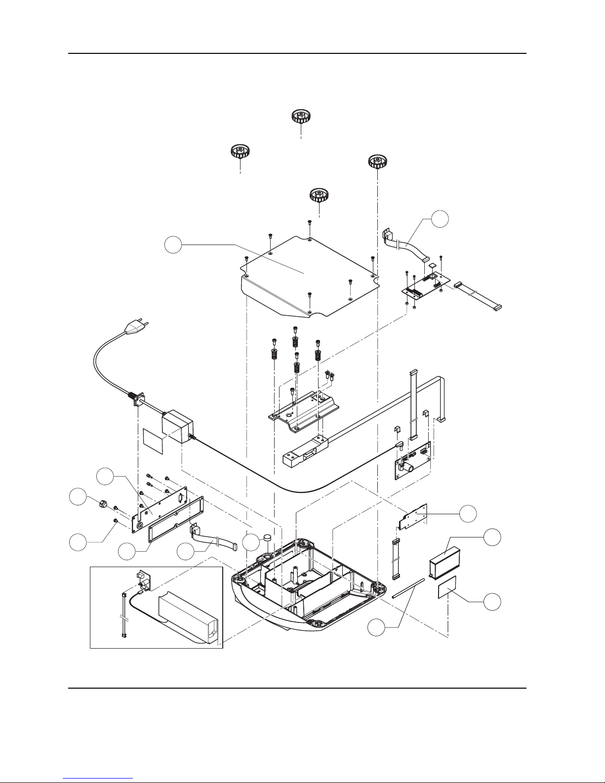
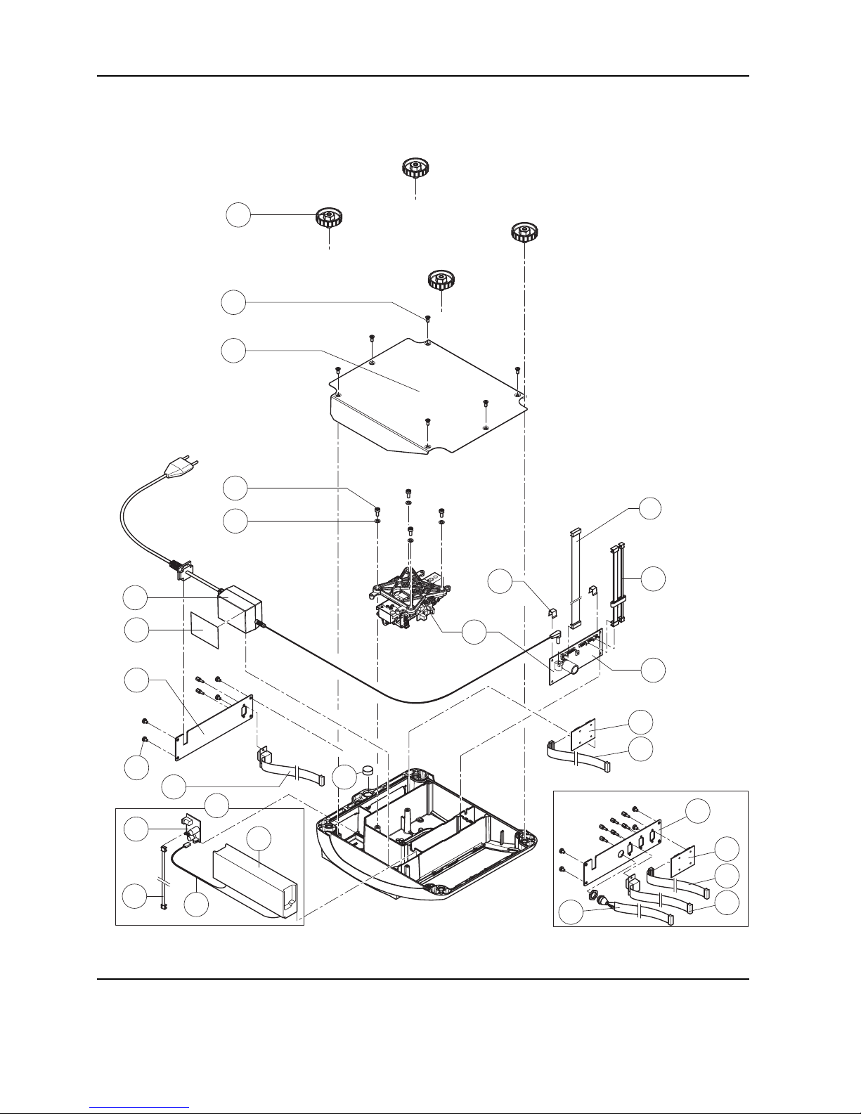
Scales with strain gauge load cells (continued)
11
1
2
5
4
6
8
9
10
16
12
13
14
17
18
3
7
19c
19d
19a
19b
19
15
25
22
23
24
14
26
27
20
21
20
14
21
26
27
Optional analog interface
Service Manual 21203788C 09/03 2-5
Viper M, L, D and T Scales/Viper RM, RL, RD and RT Terminals Section 2 Viper scales with small platform
Item Quantity Description Order No.
1 4 adjustable foot ∅ 1.7" (44mm)/ M10 x 0.75mm 21203109
2 6 countersunk Torx screw M4 x 10 *
3 1 bottom plate for small platform model –
4 4 button head Torx screw M4 x 12 *
5 4 wide flange washer 4.3 x 20 *
6 4 overload spring **
7 1 overload stop adjustment screw (with certain production series only) **
8 2 countersunk Torx screw M6 x 16 *
9 1 overload plate for small platform model –
10 1 load cell with cable (certifiable)
(Note: only “LC...” load cells are available as spare parts!)
Weighing range 7.5lb (3kg):
C5MRS or (21203143)
LC0765-5-MRV 21203873
Weighing range 12lb (6kg):
C10MRS or (21203144)
LC0765-10-MRV 21203874
Weighing range 24lb (12kg):
C20MRS or (21203145)
LC0765-20-MRV 21203875
11 1 bench AC adapter:
US version, internal (always order together with item 16) 21203122
US version for scales with rechargeable battery and Viper T scales 21255102
12 2 spring clip * 21203166
13 1 analog PCB Viper DMS 21203092
14 1 RS cable 18.1" (460mm) 21203168
15 1 A/D cable 4.3" (110 mm) for small platform model 21203164
16 1 adhesive patch for AC adapter or battery 21203184
17 1 RS connector plate for Viper M/L/D (various types, depending on the equipment) –
18 4 raised cheese head Torx screw M4 x 6 *
19 For scales with rechargeable battery only:
19a 1 rechargeable battery 12V/2,2Ah (always order together with item 16) 21203232
19b 1 battery cable (charging PCB – battery) 21203231
19c 1 charging circuit print 21204033
19d 1 connection cable (charging PCB – analog PCB) 21203233

2-6 09/03 Service Manual 21203788C
Section 2 Viper scales with small platform Viper M, L, D and T Scales/Viper RM, RL, RD and RT Terminals
Scales with strain gauge load cells (continued)
11
1
2
5
4
6
8
9
10
16
12
13
14
17
18
3
7
19c
19d
19a
19b
19
15
25
22
23
24
14
26
27
20
21
20
14
21
26
27
Optional analog interface
Service Manual 21203788C 09/03 2-7
Viper M, L, D and T Scales/Viper RM, RL, RD and RT Terminals Section 2 Viper scales with small platform
20 1 PCB RS option (2 x RS232C), standard with Viper T 21203476
21 1 connection cable RS option 15" (380mm) 21203490
22 1 PCB optional analog interface 21203383
23 1 EPROM with interface software (for optional analog interface)
EPROM for Viper L and D analog interface 21203915
EPROM for Viper T analog interface 21255318
24 1 connection cable for optional analog interface 9.9" (250mm) 21203604
25 1 level bubble 21203204
26 1 PS2 cable 18.1"/460mm, (keyboard connection, for Viper T only) 21204107
27 1 connector plate Viper T for 3 RS interfaces and 1 keyboard cable: –
standard scale: 1x PCB RS Option, 1x RS cable 18.1", 1x PS2 cable
scale with optional analog interface: 3x RS cable 18.1", 1x PS2 cable
* included in the fasteners set (chapter 3) ** see section 4 “Replacing the load cell” – not available as spare part
2-8 09/03 Service Manual 21203788C
Section 2 Viper scales with small platform Viper M, L, D and T Scales/Viper RM, RL, RD and RT Terminals
1.2 Scales with strain gauge load cells
and IP65 protection
1
2
3
4
5
6
7
8
9
Service Manual 21203788C 09/03 2-9
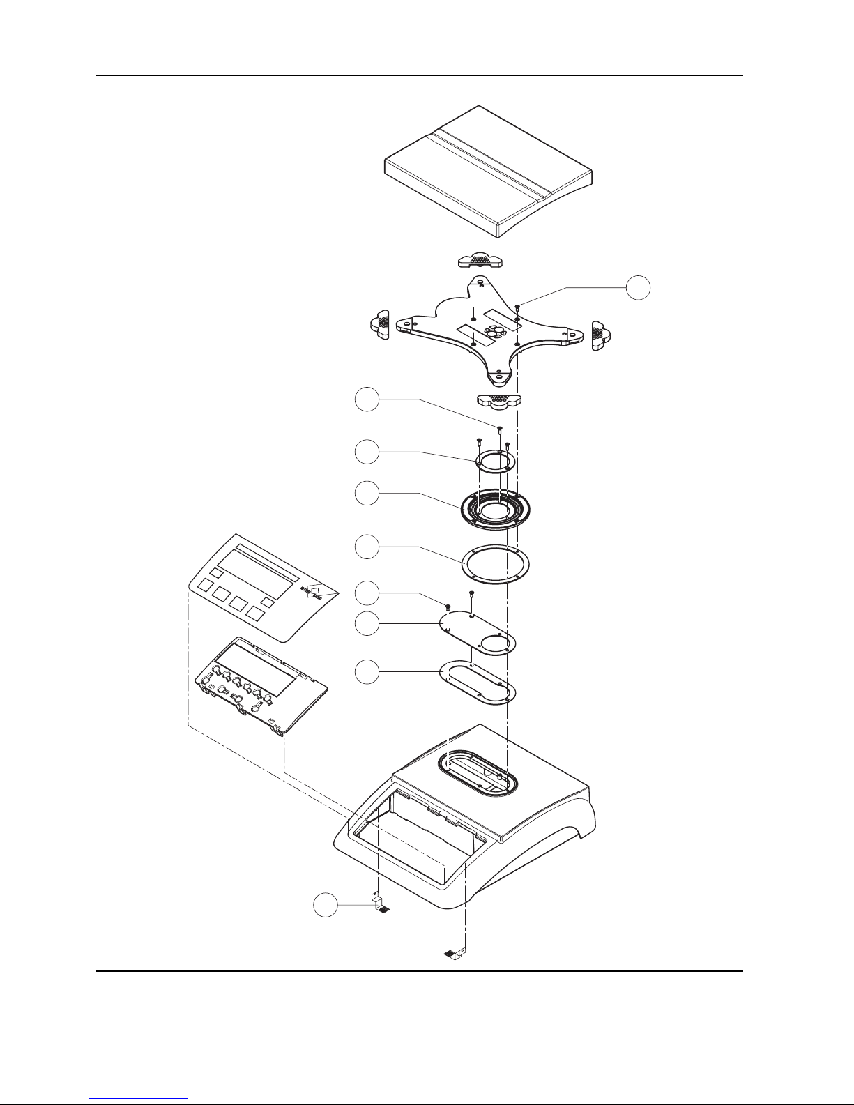
Viper M, L, D and T Scales/Viper RM, RL, RD and RT Terminals Section 2 Viper scales with small platform
Item Quantity Description Order No.
1 1 packing for cover plate 21203235
2 1 cover plate –
3 2 countersunk Torx screw M3 x 8 *
4 1 flange D = 100mm –
5 1 diaphragm 21203077
6 1 flange D = 58mm –
7 3 countersunk Torx screw M3 x 10 *
8 4 countersunk Torx screw M3 x 8 *
9 2 EMC clamp 21203480
* included in the fasteners set (chapter 3)
– not available as spare part
Note: Parts of the scale not numbered in the illustration are included in the normal version (chapter 1.1).
2-10 09/03 Service Manual 21203788C
Section 2 Viper scales with small platform Viper M, L, D and T Scales/Viper RM, RL, RD and RT Terminals
Scales with strain gauge load cells and IP65 protection (continued)
6
2
1
7
6
3
5
4
8
10
9
8
10
9
11
Service Manual 21203788C 09/03 2-11
Viper M, L, D and T Scales/Viper RM, RL, RD and RT Terminals Section 2 Viper scales with small platform
Item Quantity Description Order No.
1 1 bottom plate for small platform model IP65 version 21203511
2 1 RS connector plate IP65 version (various types, depending on the equipment) –
3 1 air supply/extraction filter 21203860
4 1 packing for RS connector plate 21203236
5 6 raised cheese head Torx screw M4 x 6 *
6 1 RS cable 460mm IP65 21203717
7 1 PCB RS option (2 x RS232C) IP65 21255081
8 1 pressure equalizer 21203611
9 1 pressure equalizer tube LA 21203862
10 1 adhesive patch for pressure equalizer 21203184
11 1 level bubble 21203204
* included in the fasteners set (chapter 3)
– not available as spare part
Note: Parts of the scale not numbered in the illustration are included in the normal version (chapter 1.1).
2-12 09/03 Service Manual 21203788C
Section 2 Viper scales with small platform Viper M, L, D and T Scales/Viper RM, RL, RD and RT Terminals
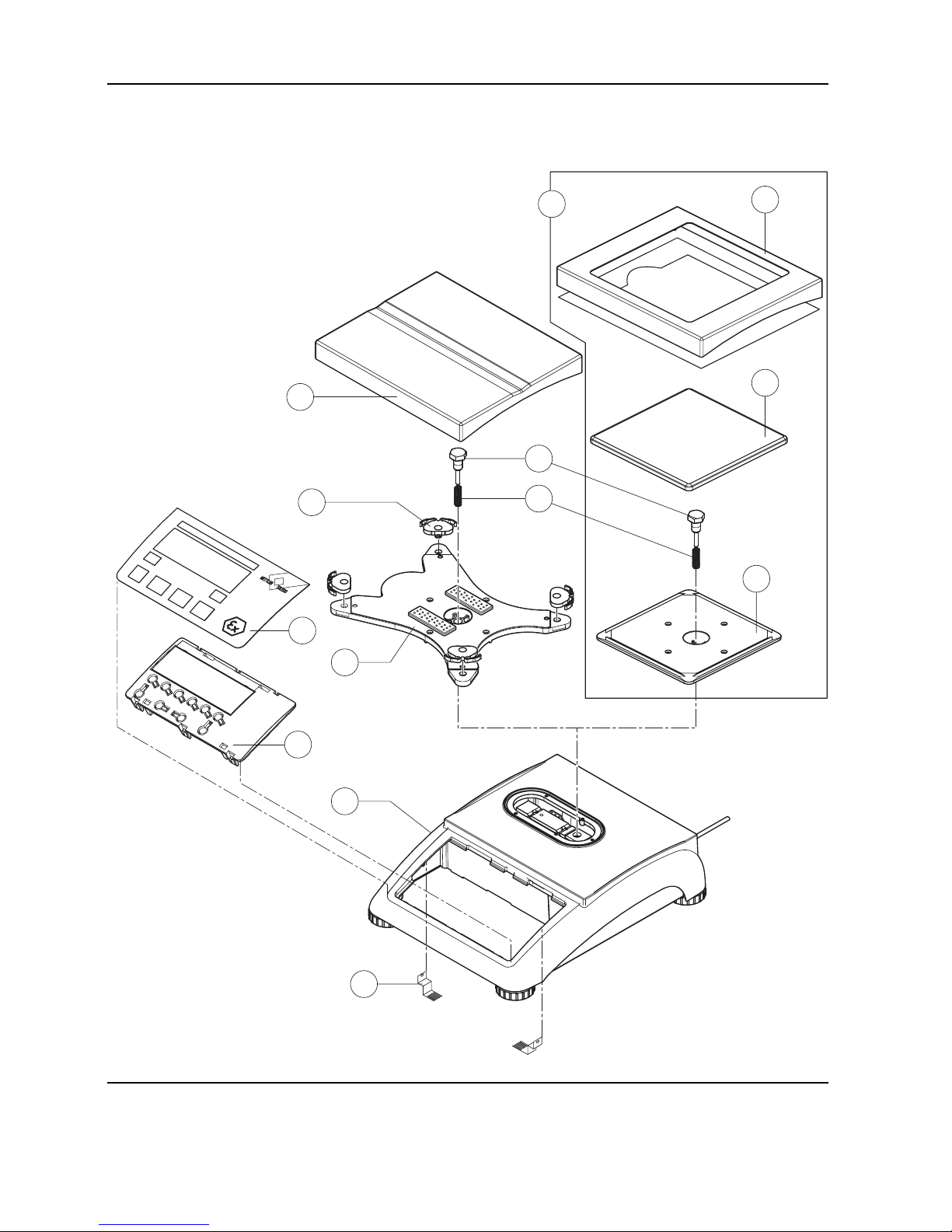
1.3 Scales with strain gauge load cells, Ex version
2
3
4
1
6
7
5
8
Service Manual 21203788C 09/03 2-13
Viper M, L, D and T Scales/Viper RM, RL, RD and RT Terminals Section 2 Viper scales with small platform
Item Quantity Description Order No.
1 1 platter 7.9" x 9.5" (200 x 240mm) 21203071
2 4 rubber cushion (1 piece)
1)
21203073
3 2 countersunk Torx screw M6 x 30 *
4 1 pan support plate 7.9" x 9.5" (200 x 240mm) –
5 1 housing, VIPER with small platform –
6 1 keypad overlay Chapter 2
7 1 mounting plate and display unit (digital PCB with LCD and back-light unit) Chapter 2
8 2 EMC clamp 21203480
* included in the fasteners set (chapter 3)
– not available as spare part
1)
New rubber cushions have a hole in the surface to assist with assembly. A pin can be used to insert the cushion into the
corresponding drilled hole in the pan support plate. Earlier rubber cushions did not have this assembly aid.
2-14 09/03 Service Manual 21203788C
Section 2 Viper scales with small platform Viper M, L, D and T Scales/Viper RM, RL, RD and RT Terminals
Scales with strain gauge load cells, Ex version (continued)
1
2
5
4
6
8
9
10
3
7
20
14
19
17
12
13
16
15
11
18

Service Manual 21203788C 09/03 2-15
Viper M, L, D and T Scales/Viper RM, RL, RD and RT Terminals Section 2 Viper scales with small platform
Item Quantity Description Order No.
1 4 adjustable foot ∅ 1.7" (44mm)/ M10 x 0.75mm 21203109
2 6 countersunk Torx screw M4 x 10 *
3 1 bottom plate for small platform model –
4 4 button head Torx screw M4 x 12 *
5 4 wide flange washer 4.3 x 20 *
6 4 overload spring **
7 1 overload stop adjustment screw (with certain production series only) **
8 2 countersunk Torx screw M6 x 16 *
9 1 overload plate for small platform model –
10 1 load cell with cable (certifiable)
Weighing range 7.5lb (3kg):
LC0765-5-MRV 21203873
Weighing range 12lb (6kg):
LC0765-10-MRV 21203874
Weighing range 24lb (12kg):
LC0765-20-MRV 21203875
11 1 wire harness Ex 21203732
12 2 spring clip * 21203166
13 1 analog PCB Viper Ex DMS 21203577
14 1 grounding screw EX 21050066
15 1 A/D cable 4.3" (110 mm) for small platform model 21203164
16 1 connection cable Ex 4 pins 21203852
17 1 connector plate Ex –
18 4 raised cheese head Torx screw M4 x 6 *
19 2 raised cheese head Torx screw M4 x 8 with tooth lock washer –
20 1 level bubble 21203204
* included in the fasteners set (chapter 3) ** see section 4 “Replacing the load cell” – not available as spare part
2-16 09/03 Service Manual 21203788C
Section 2 Viper scales with small platform Viper M, L, D and T Scales/Viper RM, RL, RD and RT Terminals
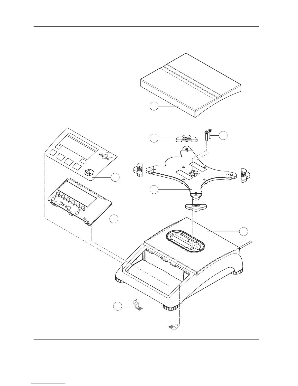
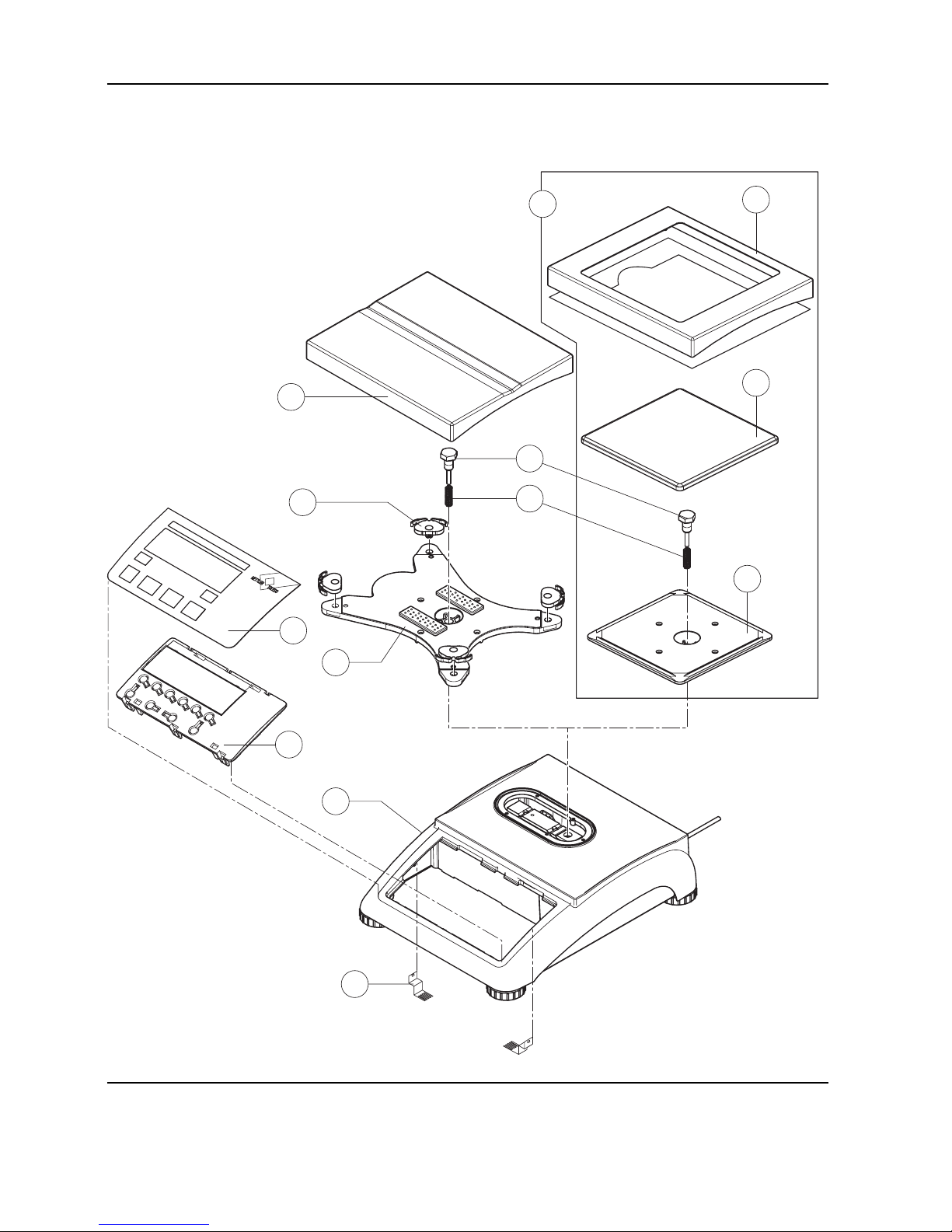
1.4 Scales with MonoBloc load cells (not including Ex version)
7
8
3
1
2
4
5
6
9
9a
9b
9c
10

Service Manual 21203788C 09/03 2-17
Viper M, L, D and T Scales/Viper RM, RL, RD and RT Terminals Section 2 Viper scales with small platform
Item Quantity Description Order No.
1 1 platter 7.9" x 9.5" (200 x 240mm) for 12lb scale (6kg) 21203071
2 4 pan mount (rubber cushion) 21203238
3 1 hexagon screw for load plate support –
4 1 fastener spring –
5 1 load plate support 7.9" x 9.5" (200 x 240mm) –
6 1 housing VIPER with small platform –
7 1 keypad overlay Chapter 2
8 1 mounting plate and display unit (digital PCB and display compl.) Chapter 2
9 For 6lb (3kg) model only:
9a 1 draft shield and screen 21203849
9b 1 platter 6.5" x 6.5" (165 x 165mm) 00225158
9c 1 load plate support 16.5" x 6.5" (165 x 165mm) –
10 2 EMC clamp 21203480
* included in the fasteners set (chapter 3)
– not available as spare part
2-18 09/03 Service Manual 21203788C
Section 2 Viper scales with small platform Viper M, L, D and T Scales/Viper RM, RL, RD and RT Terminals
Scales with MonoBloc load cells (continued)
8
1
2
5
4
13
9
10
11
14
15
12
3
16c
16d
16a
16b
16
6
7
19
17
18
17
11
18
20
21

Service Manual 21203788C 09/03 2-19
Viper M, L, D and T Scales/Viper RM, RL, RD and RT Terminals Section 2 Viper scales with small platform
Item Quantity Description Order No.
1 4 adjustable foot ∅ 1.7" (44mm)/ M10 x 0.75mm 21203109
2 6 countersunk Torx screw M4 x 10 *
3 1 bottom plate for small platform model –
4 4 cylinder head Torx screw M4 x 12 *
5 4 flange washer 4.3 x 9 –
61 weighing modules (load cell and analog PCB):
weighing module 3002 for 6lb scale (3kg) 11102685
weighing module 6001 for 12lb scale (6kg) 11102686
7 1 cell cable MB SM with ferrite ring 21203289
81 bench AC adapter:
US version, internal (always order together with item 13) 21203122
US version for scales with rechargeable battery and Viper T scales 21255102
9 2 spring clip * 21203166
10 1 analog PCB Viper MonoBloc 21203100
11 1 RS cable 18.1" (460mm) 21203168
12 1 A/D cable 4.3" (110 mm), for small platform model 21203164
13 1 adhesive strip for AC adapter or battery 21203184
14 1 RS connector plate for Viper M/L/D (various types, depending on the equipment) –
15 4 raised cheese head Torx screw M4 x 6 *
16 For scales with rechargeable battery only:
16a 1 rechargeable battery 12V/2,2Ah (always order together with item 13) 21203232
16b 1 battery cable (charging PCB – battery) 21203231
16c 1 charging circuit print 21204033
16d 1 connection cable (charging PCB – analog PCB) 21203233
17 1 PCB RS option (2 x RS232C), standard with Viper T 21203476
18 1 connection cable RS option 15" (380mm) 21203490
19 1 level bubble 11101335
20 1 PS2 cable 18.1"/460mm, (keyboard connection, for Viper T only) 21204107
21 1 connector plate Viper T for 3 RS interfaces and 1 keyboard cable –
(1x PCB RS Option, 1x RS cable 18.1", 1x PS2 cable)
* included in the fasteners set (chapter 3)
– not available as spare part
2-20 09/03 Service Manual 21203788C
Section 2 Viper scales with small platform Viper M, L, D and T Scales/Viper RM, RL, RD and RT Terminals
1.5 Scales with MonoBloc load cells, Ex version
7
8
3
1
2
4
5
6
9
9a
9b
9c
10
Service Manual 21203788C 09/03 2-21
Viper M, L, D and T Scales/Viper RM, RL, RD and RT Terminals Section 2 Viper scales with small platform
Item Quantity Description Order No.
1 1 platter 7.9" x 9.5" (200 x 240mm) for 12lb scale (6kg) 21203071
2 4 pan mount (rubber cushion) 21203238
3 1 hexagon screw for load plate support –
4 1 fastener spring –
5 1 load plate support 7.9" x 9.5" (200 x 240mm) –
6 1 housing VIPER with small platform –
7 1 keypad overlay Chapter 2
8 1 mounting plate and display unit (digital PCB and display compl.) Chapter 2
9 For 6lb (3kg) model only:
9a 1 draft shield and screen 21203849
9b 1 platter 6.5" x 6.5" (165 x 165mm) 00225158
9c 1 load plate support 16.5" x 6.5" (165 x 165mm) –
10 2 EMC clamp 21203480
* included in the fasteners set (chapter 3)
– not available as spare part
2-22 09/03 Service Manual 21203788C
Section 2 Viper scales with small platform Viper M, L, D and T Scales/Viper RM, RL, RD and RT Terminals
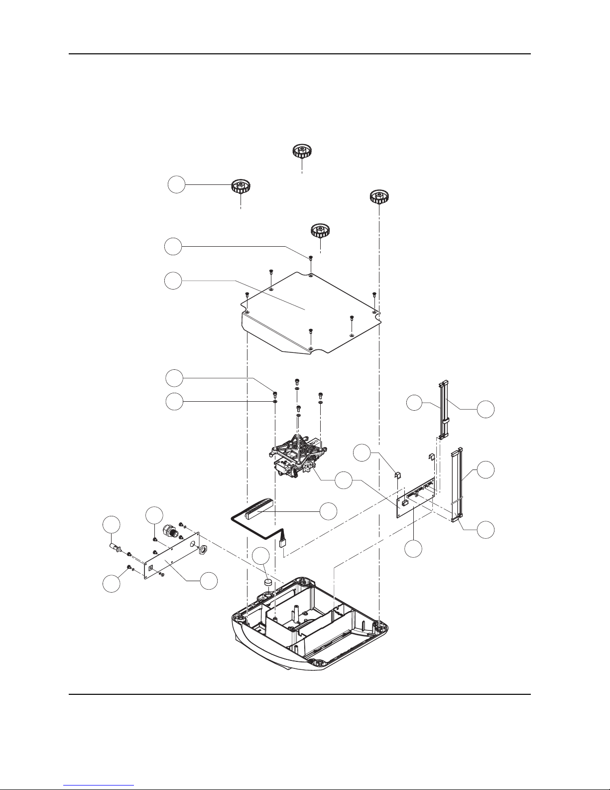
Scales with MonoBloc load cells, Ex version (continued)
1
2
5
4
3
6
17
9
7
13
10
12
8
11
16
14
13
15
 Loading...