

Page 1
Service Manual
METTLER TOLEDO
Viper M, L, D and T Scales
Viper RM, RL, RD and RT Terminals
On
Off
Zero
Tare
Sam
ple
Print
Sam
ple
Size
Scale
Clear
C
Info
Units
On
O
ff
Zero Tare Sample
P
rin
t
Sam
ple
Size
Scale
Info
U
nits
C
lear
C
Page 2

Page 3

General
About this service manual
Service concept
Product overview
1
2
Viper scales with small platform
Strain Gauge, IP65, MonoBloc, Ex
3
Viper scales with large platform
Strain Gauge, IP65, MonoBloc, Ex
4
5
Technician setup
6
Miscellaneous information
7
8
9
10
11
12
Exploded view drawings
Spare parts lists
Exploded view drawings
Spare parts lists
Accessing scale setup data
Entering scale setup data
Service Manual 21203788C Viper M, L, D and T Scales/Viper RM, RL, RD and RT Terminals
Technical data
Overview of weighing cells an preloads
Geographical table
Software
Software architecture
Error messages
Temperature compensation data
Repair of Viper scales
Repairs and replacement of components
Viper terminals
Exploded view drawings
Spare parts lists
Upgrade kits
Repair of Viper terminals
Repairs and replacement of components
Page 4

Page 5

Contents Page
1 How to use this service manual ........................................................................................................ 1-2
1.1 General ............................................................................................................................................ 1-2
1.2 Layout of the service manual .............................................................................................................. 1-2
1.3 Working with the service manual ........................................................................................................ 1-2
2 Service concept ............................................................................................................................... 1-3
3 Introducing the Viper scales product group ........................................................................................ 1-3
4 The Viper terminals .......................................................................................................................... 1-3
5 Safety.............................................................................................................................................. 1-4
6 Environmental protection .................................................................................................................. 1-4
Section 1
General
Page 6

1-2 09/03 Service Manual 21203788C
Section 1 General Viper M, L, D and T Scales/Viper RM, RL, RD and RT Terminals
1 How to use this service manual
1.1 General
This service manual contains instructions for the repair and maintenance work to be performed by service engineers.
It is assumed that the reader is familiar with the operation of the scales and terminals, and can refer to the relevant operating
instructions when necessary.
1.2 Layout of the service manual
This manual comprises nine main sections:
• General: Section 1gives instructions on using the service manual, and also provides an overview of the Viper scales and
terminals covered by it.
• Viper scales with small platform: Section 2 contains the exploded view drawings and spare parts lists for Viper scales with
the small platform.
• Viper scales with large platform: Section 3 contains the exploded view drawings and spare parts lists for Viper scales with
the large platform.
• Viper terminals: Section 4 contains the exploded view drawings and spare parts lists for Viper terminals, as well as a list of
available upgrade kits.
• Repair of Viper scales: Section 5 describes all repair work and the replacement of components for Viper scales with large
and small platforms.
• Repair of Viper terminals: Section 6 describes all repair work and the replacement of components for Viper terminals.
• Technician setup: Section 7 describes how to enter scale data, calibrate the weighing system and use the diagnostic
functions.
• Miscellaneous information: Section 8 contains technical information on the Viper product group, plus an overview of all
load cells and preloads and a table of geographical adjustment values. In addition you will find instructions on connecting
weighing platforms to Viper terminals and information on appropriate load cells, as well as important information on
attaching a second weighing platform the the optional analog interface of Viper scales and terminals.
• Software: Section 9 contains information on the various software versions. It also describes typical error messages that can
appear following service work and provides troubleshooting instructions.
1.3 Working with the service manual
The section number and title are printed in the header of every page in the service manual. Each footer shows the order number
for the manual, the date issued and the page number.
The pages are numbered in the footer. First comes the section number, then a hyphen followed by the page number, starting with
1 in every section.
The exploded view drawings are provided as a guide for disassembly and assembly work and for identifying the order numbers
for spare parts.
When ordering spare parts, please use the information given in the spare parts lists. The item numbers in the first column
correspond to those on the exploded view drawing opposite.
Page 7

Service Manual 21203788C 09/03 1-3
Viper M, L, D and T Scales/Viper RM, RL, RD and RT Terminals Section 1 General
2 Service concept
The scales have been designed so that defective components can be replaced with just a few simple tools. The LC-PT45 printer
for service is not required, as almost all parameters can be configured with the keyboard of the scale (in special cases
temperature compensation data of the MonoBloc load cell may need to be entered using a computer).
As you can see, we have kept it simple for efficient servicing.
3 Introducing the Viper scales product group
The Viper scales product group comprises the following models, which are all covered by this manual:
Viper M scales
Viper M scales possess basic weighing functions for simple weighing duties. Special versions of these scales are also available
(Viper EX M and Viper EX M MB) for use in explosion hazard zones (Class 1, Division 1) with the PSUx power supply unit or the
PSU power supply unit/interface.
Viper L scales
In addition to basic weighing functions, Viper L counting scales also have built-in functions for piece counting. An extended
keypad and a display with a visual weighing-in aid are available in order to use these additional functions.
Viper D scales
Viper D scales are counting scales providing an additional numeric keypad and ID functions.
Viper T scales
Viper T scales are the top-of-the-range models in the product group. These counting scales support a wide array of useful
functions. They have a dot matrix display with graphics capability and a numeric keypad. The various menu functions are
controlled by soft keys in the display, i.e. context-sensitive screen buttons which change according to the momentary status of
the menu. This scale type is also available for applications other than piece counting (such as SQC 16 and Remote).
Common features
Apart from the differences with regard to functions and operating and display elements, all models in the Viper product group
have the following common features:
– Depending on the weighing range, some models are only available with the small platform, some only with the large platform
and some with both. The essential difference between the two platform sizes is in their external dimensions and the type of
load cell used.
– All models are designed either for direct connection to the AC power line or contain a built-in rechargeable battery. Recharge-
able battery scales are connected to the AC power line via an AC adapter. Viper EX scales are powered by an external AC
adapter.
– All models are certifiable.
– The load cells are either of the strain gauge or MonoBloc type.
4 The Viper terminals
In terms of functionality and features the Viper RM, RL, RD and RT terminals exactly match the respective scale models (M, L, D
and T, see above). Using appropriate weighing platforms the Viper terminals allow to build customized weighing systems.
Page 8
1-4 09/03 Service Manual 21203788C
Section 1 General Viper M, L, D and T Scales/Viper RM, RL, RD and RT Terminals
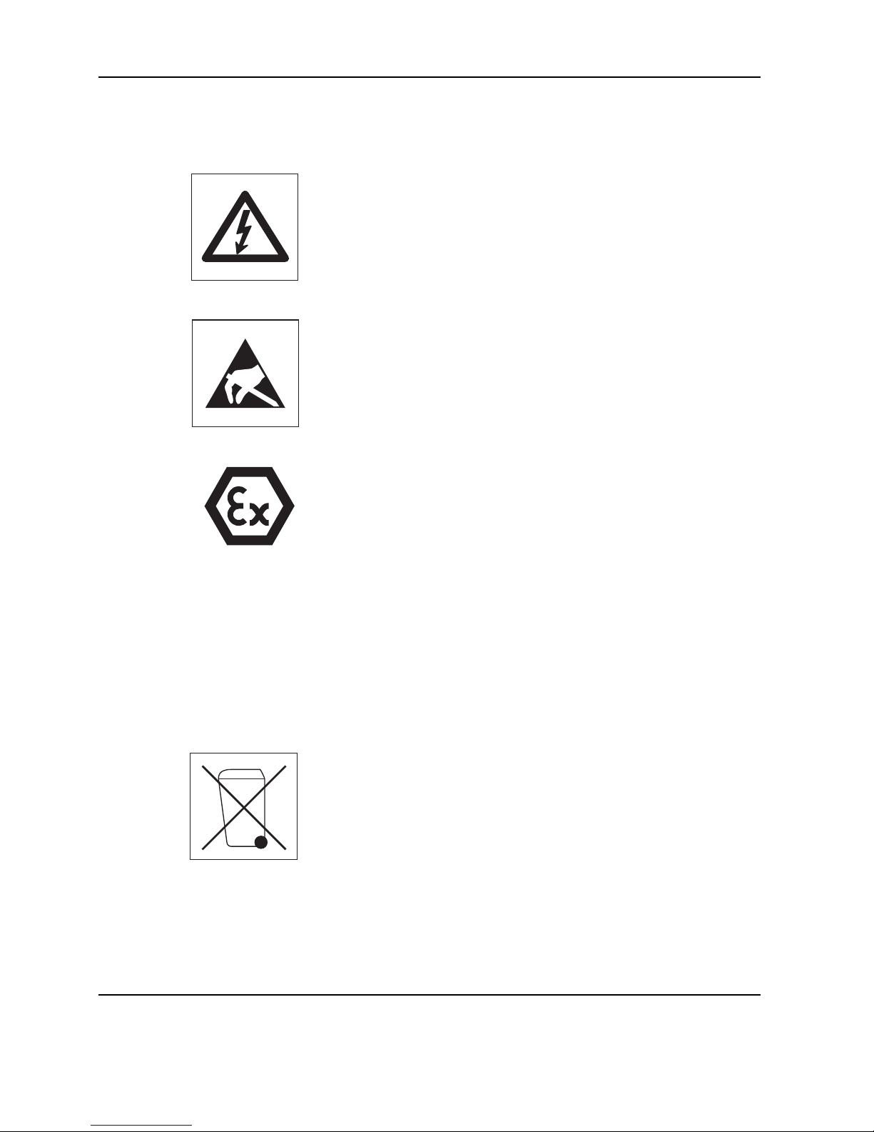
5 Safety
When carrying out service or repair work, always observe the following:
• Before opening the scale or terminal, isolate it from the AC power line (pull out the
plug).
• The scales and terminals contain precision electronic components that are
sensitive to electrostatic discharge. We recommend that you wear a grounding
wrist strap when doing any work in the interior of the scale or terminal, in order to
prevent any electrostatic charge building up. Grounding wrist straps are commercially available from electronic component suppliers.
• Servicing work in explosion hazard zones is strictly prohibited. Ignition power
could inadvertently be generated, causing an explosion. Servicing work should
therefore only be undertaken in secure areas. Please also observe all special
instructions in this Service Manual relating to work on Viper scales that are
approved for use in potentially explosive environments. Such instructions are
indicated by the adjacent symbol.
6 Environmental protection
Disposal of rechargeable batteries
Some models in the Viper product group have a built-in rechargeable battery. This
contains heavy metals which could be hazardous to the environment. The battery is
therefore classified as a hazardous waste, which must not be disposed of as normal
domestic refuse. Please ensure that used batteries are disposed of correctly in
accordance with the relevant local regulations.
Disposal of electronic components
Dispose of defective components in strict compliance with all local and national
regulations! In many countries electronic components are classified as hazardous
waste for whose disposal there are special regulations. In some countries electronic
components are collected separately for recycling. If necessary, find out the applicable regulations from the local authorities!
Page 9

Contents Page
1 Scales ............................................................................................................................................. 2-2
1.1 Scales with strain gauge load cells (not including Ex version) ................................................................ 2-2
1.2 Scales with strain gauge load cells and IP65 protection......................................................................... 2-8
1.3 Scales with strain gauge load cells, Ex version ..................................................................................... 2-12
1.4 Scales with MonoBloc load cells (not including Ex version) ................................................................... 2-16
1.5 Scales with MonoBloc load cells, Ex version ........................................................................................ 2-20
2 Display units.................................................................................................................................... 2-24
2.1 Viper M display unit (not including Ex version) ..................................................................................... 2-24
2.2 Viper EX M display unit ...................................................................................................................... 2-26
2.3 Viper L display unit ............................................................................................................................ 2-28
2.4 Viper D display unit ........................................................................................................................... 2-30
2.5 Viper T display unit ............................................................................................................................ 2-32
3 Fasteners set ................................................................................................................................... 2-34
Repair: see Section 5
Section 2
Viper scales with small platform
Page 10
2-2 09/03 Service Manual 21203788C
Section 2 Viper scales with small platform Viper M, L, D and T Scales/Viper RM, RL, RD and RT Terminals
1 Scales
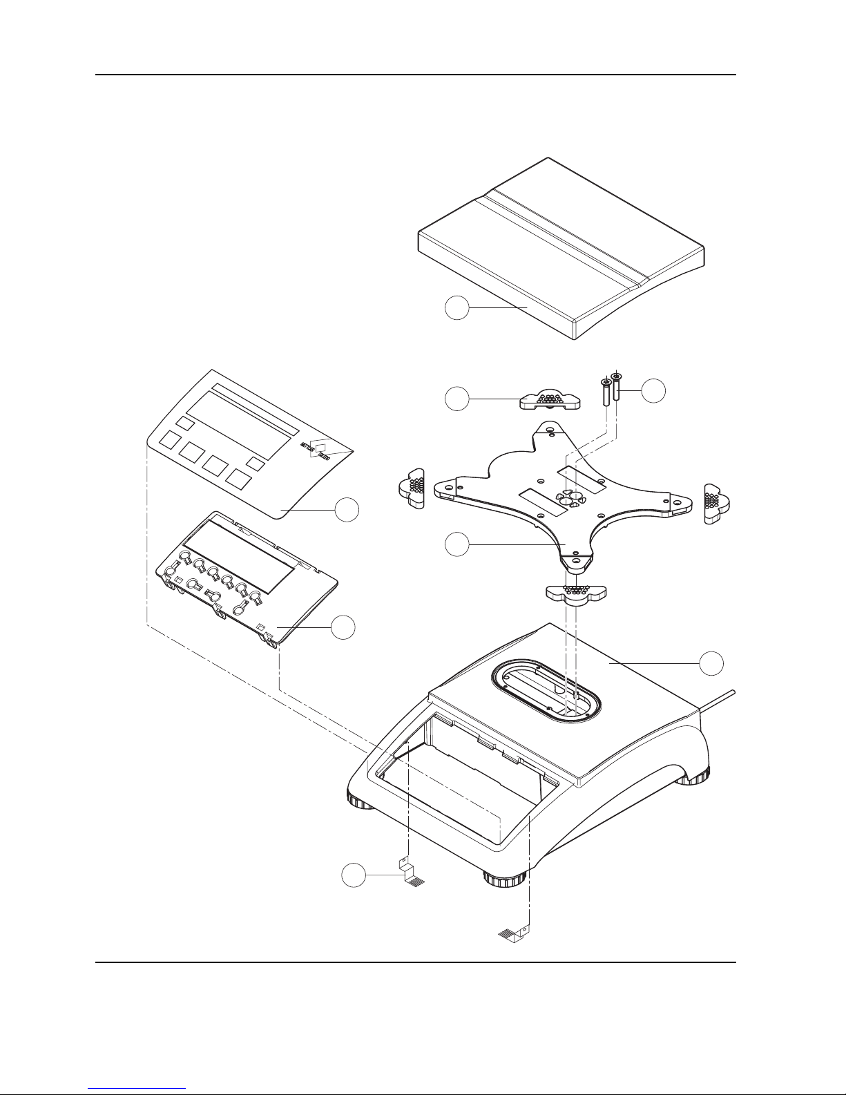
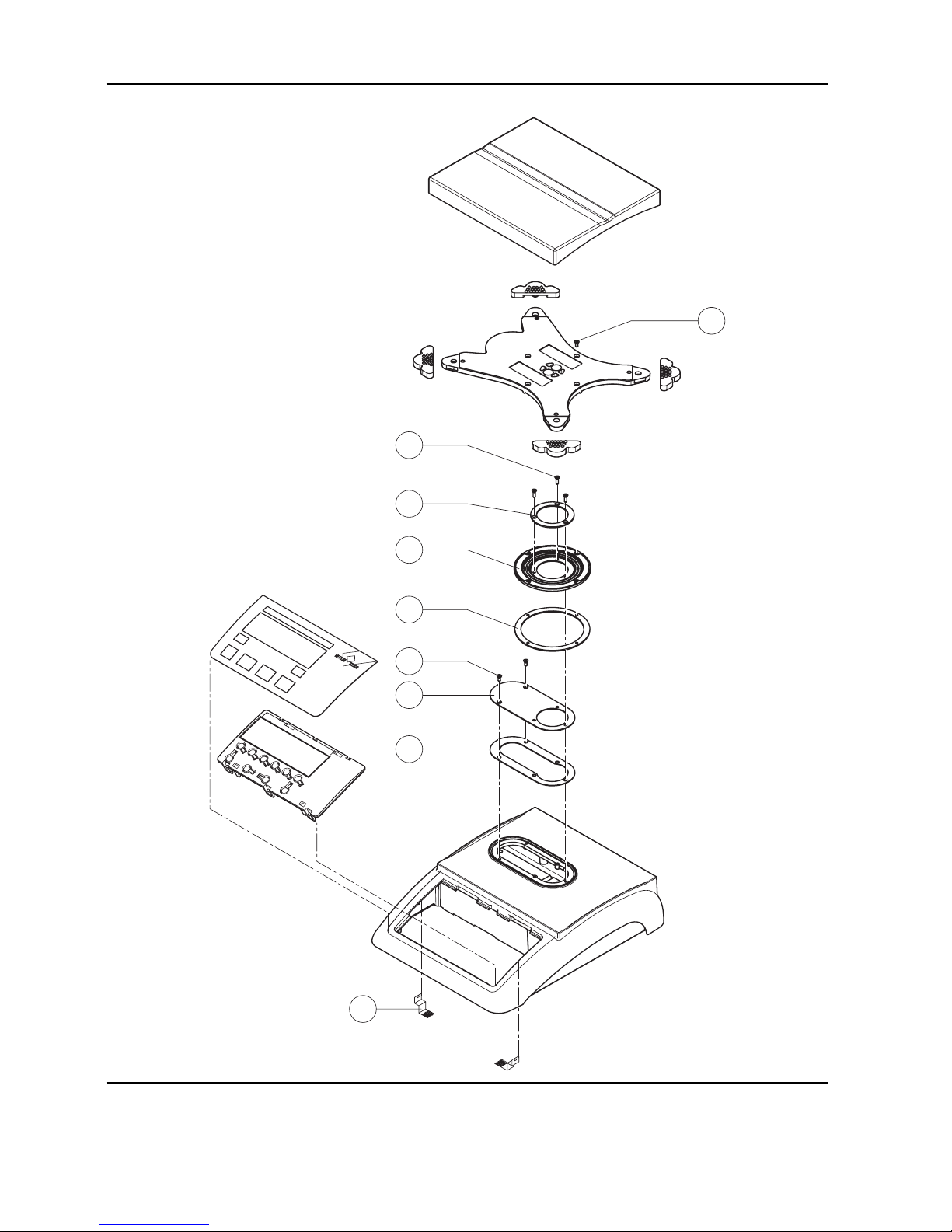
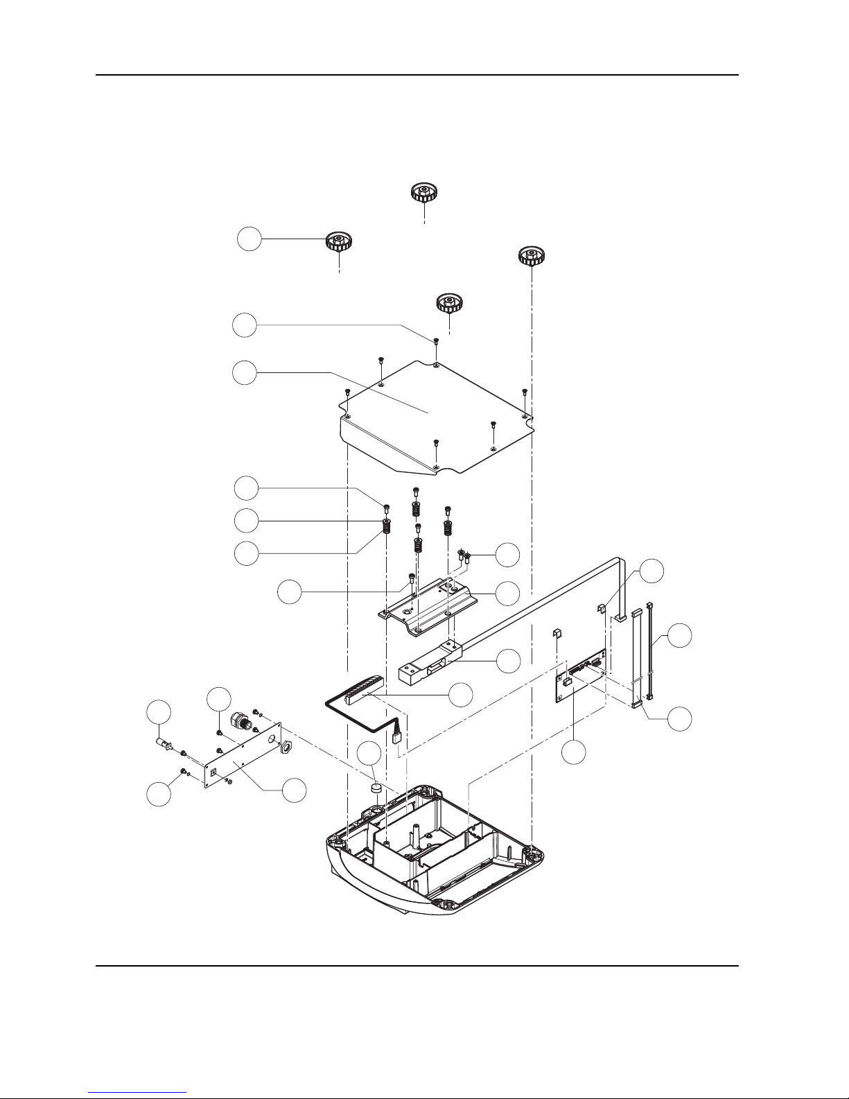
1.1 Scales with strain gauge load cells (not including Ex version)
2
3
4
1
6
7
5
8
Page 11

Service Manual 21203788C 09/03 2-3
Viper M, L, D and T Scales/Viper RM, RL, RD and RT Terminals Section 2 Viper scales with small platform
Item Quantity Description Order No.
1 1 platter 7.9" x 9.5" (200 x 240mm) 21203071
2 4 rubber cushion (1 piece)
1)
21203073
3 2 countersunk Torx screw M6 x 30 *
4 1 pan support plate 7.9" x 9.5" (200 x 240mm) –
5 1 housing, VIPER with small platform –
6 1 keypad overlay Chapter 2
7 1 mounting plate and display unit (digital PCB with LCD and back-light unit) Chapter 2
8 2 EMC clamp 21203480
* included in the fasteners set (chapter 3)
– not available as spare part
1)
New rubber cushions have a hole in the surface to assist with assembly. A pin can be used to insert the cushion into the
corresponding drilled hole in the pan support plate. Earlier rubber cushions did not have this assembly aid.
Page 12
2-4 09/03 Service Manual 21203788C
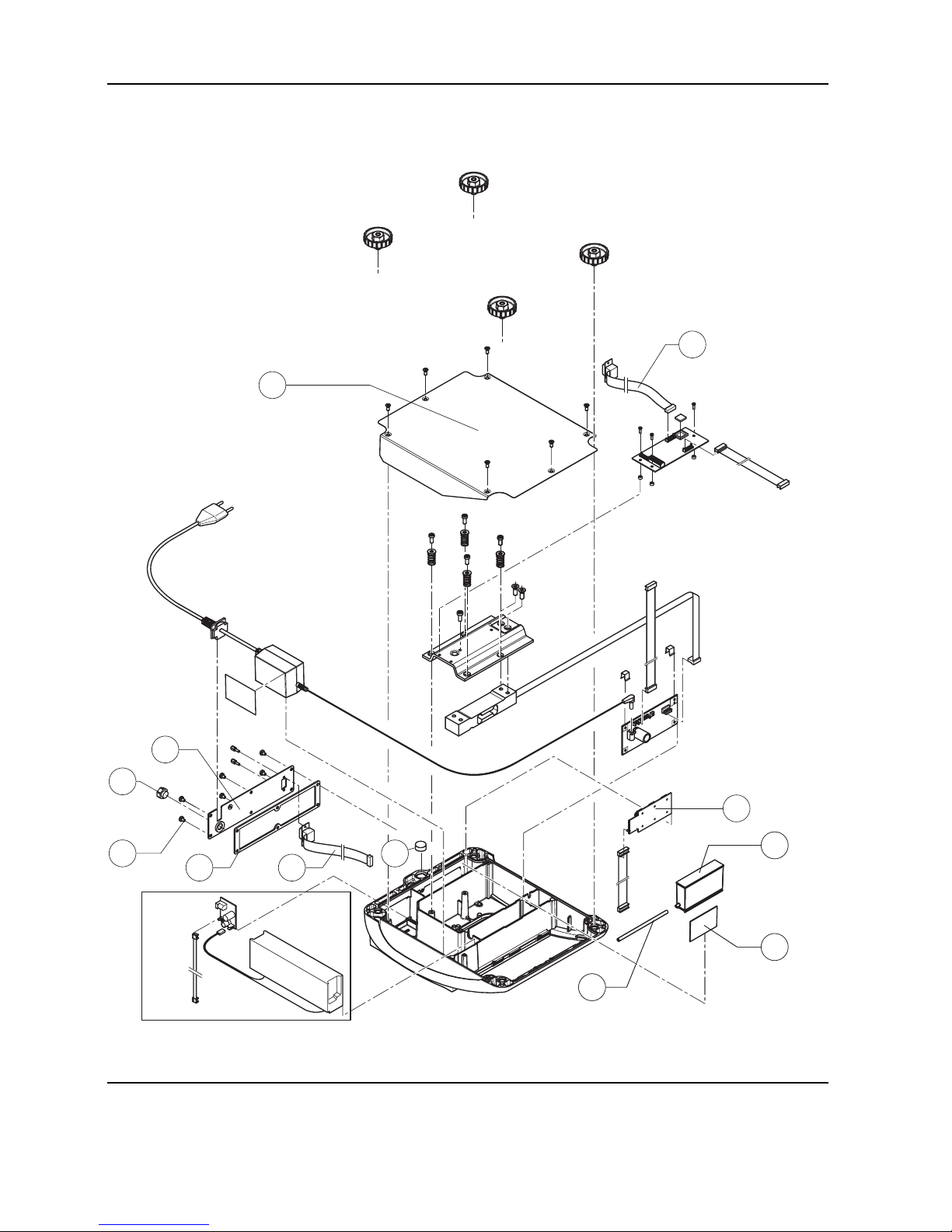
Section 2 Viper scales with small platform Viper M, L, D and T Scales/Viper RM, RL, RD and RT Terminals
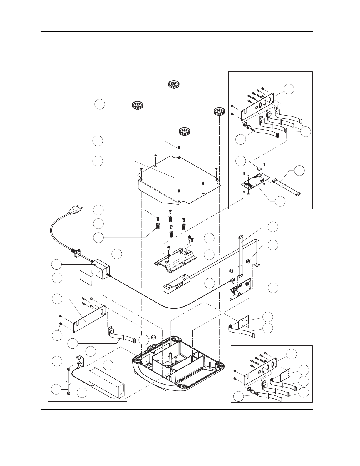
Scales with strain gauge load cells (continued)
11
1
2
5
4
6
8
9
10
16
12
13
14
17
18
3
7
19c
19d
19a
19b
19
15
25
22
23
24
14
26
27
20
21
20
14
21
26
27
Optional analog interface
Page 13

Service Manual 21203788C 09/03 2-5
Viper M, L, D and T Scales/Viper RM, RL, RD and RT Terminals Section 2 Viper scales with small platform
Item Quantity Description Order No.
1 4 adjustable foot ∅ 1.7" (44mm)/ M10 x 0.75mm 21203109
2 6 countersunk Torx screw M4 x 10 *
3 1 bottom plate for small platform model –
4 4 button head Torx screw M4 x 12 *
5 4 wide flange washer 4.3 x 20 *
6 4 overload spring **
7 1 overload stop adjustment screw (with certain production series only) **
8 2 countersunk Torx screw M6 x 16 *
9 1 overload plate for small platform model –
10 1 load cell with cable (certifiable)
(Note: only “LC...” load cells are available as spare parts!)
Weighing range 7.5lb (3kg):
C5MRS or (21203143)
LC0765-5-MRV 21203873
Weighing range 12lb (6kg):
C10MRS or (21203144)
LC0765-10-MRV 21203874
Weighing range 24lb (12kg):
C20MRS or (21203145)
LC0765-20-MRV 21203875
11 1 bench AC adapter:
US version, internal (always order together with item 16) 21203122
US version for scales with rechargeable battery and Viper T scales 21255102
12 2 spring clip * 21203166
13 1 analog PCB Viper DMS 21203092
14 1 RS cable 18.1" (460mm) 21203168
15 1 A/D cable 4.3" (110 mm) for small platform model 21203164
16 1 adhesive patch for AC adapter or battery 21203184
17 1 RS connector plate for Viper M/L/D (various types, depending on the equipment) –
18 4 raised cheese head Torx screw M4 x 6 *
19 For scales with rechargeable battery only:
19a 1 rechargeable battery 12V/2,2Ah (always order together with item 16) 21203232
19b 1 battery cable (charging PCB – battery) 21203231
19c 1 charging circuit print 21204033
19d 1 connection cable (charging PCB – analog PCB) 21203233
Page 14

2-6 09/03 Service Manual 21203788C
Section 2 Viper scales with small platform Viper M, L, D and T Scales/Viper RM, RL, RD and RT Terminals
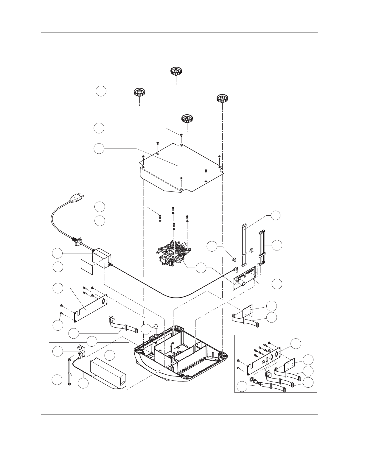
Scales with strain gauge load cells (continued)
11
1
2
5
4
6
8
9
10
16
12
13
14
17
18
3
7
19c
19d
19a
19b
19
15
25
22
23
24
14
26
27
20
21
20
14
21
26
27
Optional analog interface
Page 15
Service Manual 21203788C 09/03 2-7
Viper M, L, D and T Scales/Viper RM, RL, RD and RT Terminals Section 2 Viper scales with small platform
20 1 PCB RS option (2 x RS232C), standard with Viper T 21203476
21 1 connection cable RS option 15" (380mm) 21203490
22 1 PCB optional analog interface 21203383
23 1 EPROM with interface software (for optional analog interface)
EPROM for Viper L and D analog interface 21203915
EPROM for Viper T analog interface 21255318
24 1 connection cable for optional analog interface 9.9" (250mm) 21203604
25 1 level bubble 21203204
26 1 PS2 cable 18.1"/460mm, (keyboard connection, for Viper T only) 21204107
27 1 connector plate Viper T for 3 RS interfaces and 1 keyboard cable: –
standard scale: 1x PCB RS Option, 1x RS cable 18.1", 1x PS2 cable
scale with optional analog interface: 3x RS cable 18.1", 1x PS2 cable
* included in the fasteners set (chapter 3) ** see section 4 “Replacing the load cell” – not available as spare part
Page 16
2-8 09/03 Service Manual 21203788C
Section 2 Viper scales with small platform Viper M, L, D and T Scales/Viper RM, RL, RD and RT Terminals
1.2 Scales with strain gauge load cells
and IP65 protection
1
2
3
4
5
6
7
8
9
Page 17

Service Manual 21203788C 09/03 2-9
Viper M, L, D and T Scales/Viper RM, RL, RD and RT Terminals Section 2 Viper scales with small platform
Item Quantity Description Order No.
1 1 packing for cover plate 21203235
2 1 cover plate –
3 2 countersunk Torx screw M3 x 8 *
4 1 flange D = 100mm –
5 1 diaphragm 21203077
6 1 flange D = 58mm –
7 3 countersunk Torx screw M3 x 10 *
8 4 countersunk Torx screw M3 x 8 *
9 2 EMC clamp 21203480
* included in the fasteners set (chapter 3)
– not available as spare part
Note: Parts of the scale not numbered in the illustration are included in the normal version (chapter 1.1).
Page 18
2-10 09/03 Service Manual 21203788C
Section 2 Viper scales with small platform Viper M, L, D and T Scales/Viper RM, RL, RD and RT Terminals
Scales with strain gauge load cells and IP65 protection (continued)
6
2
1
7
6
3
5
4
8
10
9
8
10
9
11
Page 19

Service Manual 21203788C 09/03 2-11
Viper M, L, D and T Scales/Viper RM, RL, RD and RT Terminals Section 2 Viper scales with small platform
Item Quantity Description Order No.
1 1 bottom plate for small platform model IP65 version 21203511
2 1 RS connector plate IP65 version (various types, depending on the equipment) –
3 1 air supply/extraction filter 21203860
4 1 packing for RS connector plate 21203236
5 6 raised cheese head Torx screw M4 x 6 *
6 1 RS cable 460mm IP65 21203717
7 1 PCB RS option (2 x RS232C) IP65 21255081
8 1 pressure equalizer 21203611
9 1 pressure equalizer tube LA 21203862
10 1 adhesive patch for pressure equalizer 21203184
11 1 level bubble 21203204
* included in the fasteners set (chapter 3)
– not available as spare part
Note: Parts of the scale not numbered in the illustration are included in the normal version (chapter 1.1).
Page 20
2-12 09/03 Service Manual 21203788C
Section 2 Viper scales with small platform Viper M, L, D and T Scales/Viper RM, RL, RD and RT Terminals
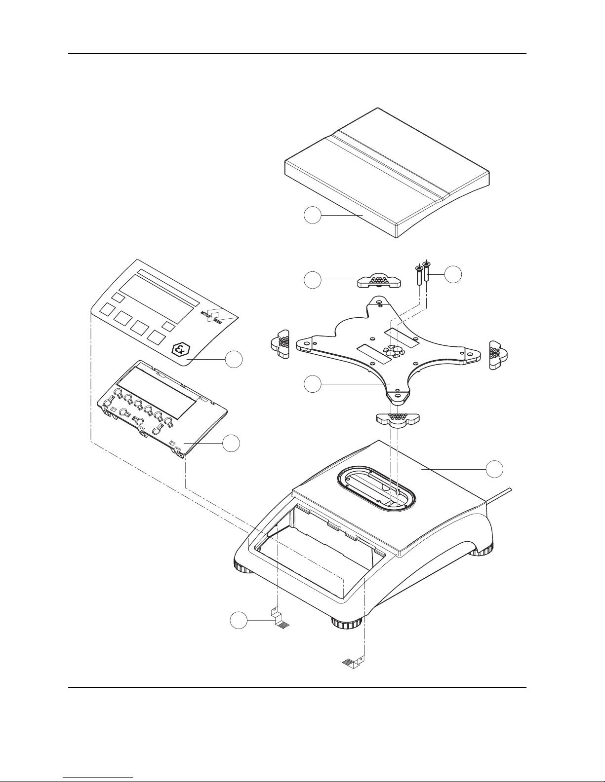
1.3 Scales with strain gauge load cells, Ex version
2
3
4
1
6
7
5
8
Page 21

Service Manual 21203788C 09/03 2-13
Viper M, L, D and T Scales/Viper RM, RL, RD and RT Terminals Section 2 Viper scales with small platform
Item Quantity Description Order No.
1 1 platter 7.9" x 9.5" (200 x 240mm) 21203071
2 4 rubber cushion (1 piece)
1)
21203073
3 2 countersunk Torx screw M6 x 30 *
4 1 pan support plate 7.9" x 9.5" (200 x 240mm) –
5 1 housing, VIPER with small platform –
6 1 keypad overlay Chapter 2
7 1 mounting plate and display unit (digital PCB with LCD and back-light unit) Chapter 2
8 2 EMC clamp 21203480
* included in the fasteners set (chapter 3)
– not available as spare part
1)
New rubber cushions have a hole in the surface to assist with assembly. A pin can be used to insert the cushion into the
corresponding drilled hole in the pan support plate. Earlier rubber cushions did not have this assembly aid.
Page 22
2-14 09/03 Service Manual 21203788C
Section 2 Viper scales with small platform Viper M, L, D and T Scales/Viper RM, RL, RD and RT Terminals
Scales with strain gauge load cells, Ex version (continued)
1
2
5
4
6
8
9
10
3
7
20
14
19
17
12
13
16
15
11
18
Page 23

Service Manual 21203788C 09/03 2-15
Viper M, L, D and T Scales/Viper RM, RL, RD and RT Terminals Section 2 Viper scales with small platform
Item Quantity Description Order No.
1 4 adjustable foot ∅ 1.7" (44mm)/ M10 x 0.75mm 21203109
2 6 countersunk Torx screw M4 x 10 *
3 1 bottom plate for small platform model –
4 4 button head Torx screw M4 x 12 *
5 4 wide flange washer 4.3 x 20 *
6 4 overload spring **
7 1 overload stop adjustment screw (with certain production series only) **
8 2 countersunk Torx screw M6 x 16 *
9 1 overload plate for small platform model –
10 1 load cell with cable (certifiable)
Weighing range 7.5lb (3kg):
LC0765-5-MRV 21203873
Weighing range 12lb (6kg):
LC0765-10-MRV 21203874
Weighing range 24lb (12kg):
LC0765-20-MRV 21203875
11 1 wire harness Ex 21203732
12 2 spring clip * 21203166
13 1 analog PCB Viper Ex DMS 21203577
14 1 grounding screw EX 21050066
15 1 A/D cable 4.3" (110 mm) for small platform model 21203164
16 1 connection cable Ex 4 pins 21203852
17 1 connector plate Ex –
18 4 raised cheese head Torx screw M4 x 6 *
19 2 raised cheese head Torx screw M4 x 8 with tooth lock washer –
20 1 level bubble 21203204
* included in the fasteners set (chapter 3) ** see section 4 “Replacing the load cell” – not available as spare part
Page 24
2-16 09/03 Service Manual 21203788C
Section 2 Viper scales with small platform Viper M, L, D and T Scales/Viper RM, RL, RD and RT Terminals
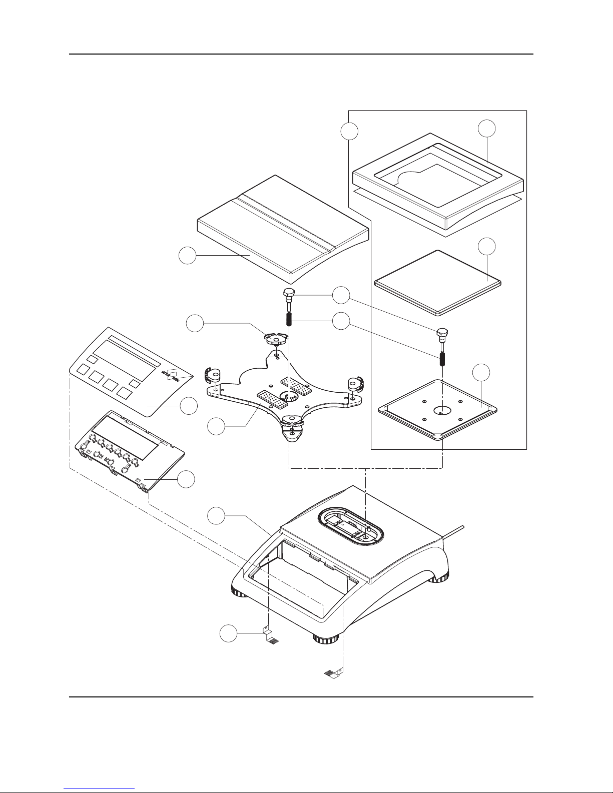
1.4 Scales with MonoBloc load cells (not including Ex version)
7
8
3
1
2
4
5
6
9
9a
9b
9c
10
Page 25

Service Manual 21203788C 09/03 2-17
Viper M, L, D and T Scales/Viper RM, RL, RD and RT Terminals Section 2 Viper scales with small platform
Item Quantity Description Order No.
1 1 platter 7.9" x 9.5" (200 x 240mm) for 12lb scale (6kg) 21203071
2 4 pan mount (rubber cushion) 21203238
3 1 hexagon screw for load plate support –
4 1 fastener spring –
5 1 load plate support 7.9" x 9.5" (200 x 240mm) –
6 1 housing VIPER with small platform –
7 1 keypad overlay Chapter 2
8 1 mounting plate and display unit (digital PCB and display compl.) Chapter 2
9 For 6lb (3kg) model only:
9a 1 draft shield and screen 21203849
9b 1 platter 6.5" x 6.5" (165 x 165mm) 00225158
9c 1 load plate support 16.5" x 6.5" (165 x 165mm) –
10 2 EMC clamp 21203480
* included in the fasteners set (chapter 3)
– not available as spare part
Page 26
2-18 09/03 Service Manual 21203788C
Section 2 Viper scales with small platform Viper M, L, D and T Scales/Viper RM, RL, RD and RT Terminals
Scales with MonoBloc load cells (continued)
8
1
2
5
4
13
9
10
11
14
15
12
3
16c
16d
16a
16b
16
6
7
19
17
18
17
11
18
20
21
Page 27

Service Manual 21203788C 09/03 2-19
Viper M, L, D and T Scales/Viper RM, RL, RD and RT Terminals Section 2 Viper scales with small platform
Item Quantity Description Order No.
1 4 adjustable foot ∅ 1.7" (44mm)/ M10 x 0.75mm 21203109
2 6 countersunk Torx screw M4 x 10 *
3 1 bottom plate for small platform model –
4 4 cylinder head Torx screw M4 x 12 *
5 4 flange washer 4.3 x 9 –
61 weighing modules (load cell and analog PCB):
weighing module 3002 for 6lb scale (3kg) 11102685
weighing module 6001 for 12lb scale (6kg) 11102686
7 1 cell cable MB SM with ferrite ring 21203289
81 bench AC adapter:
US version, internal (always order together with item 13) 21203122
US version for scales with rechargeable battery and Viper T scales 21255102
9 2 spring clip * 21203166
10 1 analog PCB Viper MonoBloc 21203100
11 1 RS cable 18.1" (460mm) 21203168
12 1 A/D cable 4.3" (110 mm), for small platform model 21203164
13 1 adhesive strip for AC adapter or battery 21203184
14 1 RS connector plate for Viper M/L/D (various types, depending on the equipment) –
15 4 raised cheese head Torx screw M4 x 6 *
16 For scales with rechargeable battery only:
16a 1 rechargeable battery 12V/2,2Ah (always order together with item 13) 21203232
16b 1 battery cable (charging PCB – battery) 21203231
16c 1 charging circuit print 21204033
16d 1 connection cable (charging PCB – analog PCB) 21203233
17 1 PCB RS option (2 x RS232C), standard with Viper T 21203476
18 1 connection cable RS option 15" (380mm) 21203490
19 1 level bubble 11101335
20 1 PS2 cable 18.1"/460mm, (keyboard connection, for Viper T only) 21204107
21 1 connector plate Viper T for 3 RS interfaces and 1 keyboard cable –
(1x PCB RS Option, 1x RS cable 18.1", 1x PS2 cable)
* included in the fasteners set (chapter 3)
– not available as spare part
Page 28
2-20 09/03 Service Manual 21203788C
Section 2 Viper scales with small platform Viper M, L, D and T Scales/Viper RM, RL, RD and RT Terminals
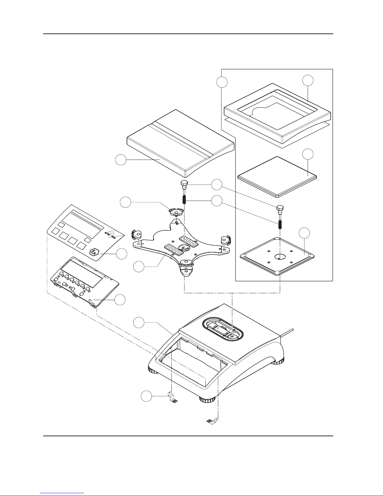
1.5 Scales with MonoBloc load cells, Ex version
7
8
3
1
2
4
5
6
9
9a
9b
9c
10
Page 29

Service Manual 21203788C 09/03 2-21
Viper M, L, D and T Scales/Viper RM, RL, RD and RT Terminals Section 2 Viper scales with small platform
Item Quantity Description Order No.
1 1 platter 7.9" x 9.5" (200 x 240mm) for 12lb scale (6kg) 21203071
2 4 pan mount (rubber cushion) 21203238
3 1 hexagon screw for load plate support –
4 1 fastener spring –
5 1 load plate support 7.9" x 9.5" (200 x 240mm) –
6 1 housing VIPER with small platform –
7 1 keypad overlay Chapter 2
8 1 mounting plate and display unit (digital PCB and display compl.) Chapter 2
9 For 6lb (3kg) model only:
9a 1 draft shield and screen 21203849
9b 1 platter 6.5" x 6.5" (165 x 165mm) 00225158
9c 1 load plate support 16.5" x 6.5" (165 x 165mm) –
10 2 EMC clamp 21203480
* included in the fasteners set (chapter 3)
– not available as spare part
Page 30
2-22 09/03 Service Manual 21203788C
Section 2 Viper scales with small platform Viper M, L, D and T Scales/Viper RM, RL, RD and RT Terminals
Scales with MonoBloc load cells, Ex version (continued)
1
2
5
4
3
6
17
9
7
13
10
12
8
11
16
14
13
15
Page 31

Service Manual 21203788C 09/03 2-23
Viper M, L, D and T Scales/Viper RM, RL, RD and RT Terminals Section 2 Viper scales with small platform
Item Quantity Description Order No.
1 4 adjustable foot ∅ 1.7" (44mm)/ M10 x 0.75mm 21203109
2 6 countersunk Torx screw M4 x 10 *
3 1 bottom plate for small platform model –
4 4 cylinder head Torx screw M4 x 12 *
5 4 flange washer 4.3 x 9 –
61 weighing modules (load cell and analog PCB):
weighing module 3002 Ex for 6lb scale (3kg) 21204011
weighing module 6001 Ex for 12lb scale (6kg) 21204012
7 1 cell PCB cable Ex 21203990
8 1 wire harness Ex 21203732
9 2 spring clip * 21203166
10 1 analog PCB Viper Ex MonoBloc 21203576
11 1 grounding screw EX 21050066
12 1 A/D cable 4.3" (110 mm), for small platform model 21203164
13 2 connection cable Ex 4 pins, for small platform model 21203852
14 1 connector plate Ex –
15 4 raised cheese head Torx screw M4 x 6 *
16 2 raised cheese head Torx screw M4 x 8 with tooth lock washer –
17 1 level bubble 11101335
* included in the fasteners set (chapter 3)
– not available as spare part
Page 32

2-24 09/03 Service Manual 21203788C
Section 2 Viper scales with small platform Viper M, L, D and T Scales/Viper RM, RL, RD and RT Terminals
2 Display units
2.1 Viper M display unit (not including Ex version)
1
2
3
4
5
7
6
Page 33

Service Manual 21203788C 09/03 2-25
Viper M, L, D and T Scales/Viper RM, RL, RD and RT Terminals Section 2 Viper scales with small platform
Item Quantity Description Order No.
1 1 keypad overlay for Viper M small platform model 21203440
2 1 display mounting plate for Viper M (always order together with item 1) 21203120
3 1 LCD for Viper M 21203134
4 1 back-light unit for Viper M 21203136
51 digital PCB Viper M
1)
VIPER DIG M digital PCB for scales with strain gauge load cell
2)
21203098
VIPER MB DIG digital PCB with FLASH Memory chip (soldered)
for scales with MonoBloc load cell
3)
21204025-MBM
6 1 EPROM with scale program for Viper M scales with strain gauge load cell 21203583
7 1 retaining screw *
* included in the fasteners set (chapter 3)
1)
without LCD and back-light unit (these parts must be ordered separately)
2)
without EPROM (must be ordered separately)
3)
the digital PCB with FLASH memory chip is always supplied with scale-specific software. The designation “MBM” following
the order number specifies the scale software that is is loaded into the FLASH Memory chip prior to shipping.
Page 34

2-26 09/03 Service Manual 21203788C
Section 2 Viper scales with small platform Viper M, L, D and T Scales/Viper RM, RL, RD and RT Terminals
2.2 Viper EX M display unit
1
2
3
4
5
7
6
8
8
Page 35

Service Manual 21203788C 09/03 2-27
Viper M, L, D and T Scales/Viper RM, RL, RD and RT Terminals Section 2 Viper scales with small platform
Item Quantity Description Order No.
1 1 keypad overlay for Viper M small platform model 21203440
2 1 display mounting plate for Viper Ex 21203734
3 1 LCD for Viper M 21203134
4 1 back-light unit for Viper M 21203136
5 1 VIPER Ex DIG digital PCB
1)
21203593
61 EPROM with scale program:
EPROM for Viper M scales with strain gauge load cell 21203583
EPROM for Viper M scales with MonoBloc load cell 21203584
7 1 retaining screw *
8 1 set of blank labels Viper Ex 22007836
* included in the fasteners set (chapter 3)
1)
supplied without software, LCD and back-light unit (these parts must be ordered separately)
Page 36

2-28 09/03 Service Manual 21203788C
Section 2 Viper scales with small platform Viper M, L, D and T Scales/Viper RM, RL, RD and RT Terminals
2.3 Viper L display unit
1
2
3
4
5
7
6
Page 37

Service Manual 21203788C 09/03 2-29
Viper M, L, D and T Scales/Viper RM, RL, RD and RT Terminals Section 2 Viper scales with small platform
Item Quantity Description Order No.
1 1 keypad overlay for Viper L small platform model 21203441
2 1 display mounting plate for Viper L (always order together with item 1) 21203491
3 1 LCD for Viper L/D 21203687
4 1 back-light unit for Viper L/D 21203137
51 digital PCB Viper L
1)
VIPER DIG L digital PCB for scales with strain gauge load cell
2)
21203097
VIPER MB DIG digital PCB with FLASH Memory chip (soldered)
for scales with MonoBloc load cell
3)
21204025-MBL
6 1 EPROM with scale program for Viper L scales with strain gauge load cell 21203588
7 1 retaining screw *
* included in the fasteners set (chapter 3)
1)
without LCD and back-light unit (these parts must be ordered separately)
2)
without EPROM (must be ordered separately)
3)
the digital PCB with FLASH memory chip is always supplied with scale-specific software. The designation “MBL” following the
order number specifies the scale software that is is loaded into the FLASH Memory chip prior to shipping.
Page 38

2-30 09/03 Service Manual 21203788C
Section 2 Viper scales with small platform Viper M, L, D and T Scales/Viper RM, RL, RD and RT Terminals
2.4 Viper D display unit
1
2
4
5
6
7
3
Page 39

Service Manual 21203788C 09/03 2-31
Viper M, L, D and T Scales/Viper RM, RL, RD and RT Terminals Section 2 Viper scales with small platform
Item Quantity Description Order No.
1 1 keypad overlay for Viper D small platform model 21203442
2 1 display mounting plate for Viper D (always order together with items 1 and 3) 21203448
3 1 pressure sensitive membrane for numeric keypad (15 keys)
1)
21203439
4 1 LCD for Viper L/D 21203687
5 1 back-light unit for Viper L/D 21203137
61 digital PCB Viper D with FLASH Memory chip (soldered)
2)
VIPER DIG D digital PCB for scales with strain gauge load cell
3)
21203524-STD
VIPER DIG D digital PCB for scales with MonoBloc load cell
3)
21203524-MBD
7 1 retaining screw *
* included in the fasteners set (chapter 3)
1)
always order together with item 1
2)
supplied without LCD and back-light unit (these parts must be ordered separately)
3)
the digital PCB with FLASH memory chip is always supplied with scale-specific software. The designations “STD” and “MBD”
following the order number specify the scale software that is is loaded into the FLASH Memory chip prior to shipping.
Page 40

2-32 09/03 Service Manual 21203788C
Section 2 Viper scales with small platform Viper M, L, D and T Scales/Viper RM, RL, RD and RT Terminals
2.5 Viper T display unit
1
2
3
4
7
5
6
7
Page 41

Service Manual 21203788C 09/03 2-33
Viper M, L, D and T Scales/Viper RM, RL, RD and RT Terminals Section 2 Viper scales with small platform
Item Quantity Description Order No.
1 1 keypad overlay for Viper T small platform model 21203129
2 1 pressure sensitive keypad membrane for numeric keypad (25 keys) 21203501
3 1 display mounting plate for Viper T (always order together with items 1 and 2) 21203507
4 1 spacer plate 21255046
5 1 LCD module 240 x 64 dots CCFL 21203515
61 digital PCB:
Viper T (counting scale) 21203996
SQC 16 21203772
Smart Remote 21203997
7 5 retaining screw *
* included in the fasteners set (chapter 3)
Page 42

2-34 09/03 Service Manual 21203788C
Section 2 Viper scales with small platform Viper M, L, D and T Scales/Viper RM, RL, RD and RT Terminals
3 Fasteners set
The fasteners set comprises all the standard components (screws and washers) required for service work on Viper scales and
terminals, plus the spring clips that hold the analog PCB in place.
Quantity Description Order No.
1 fasteners set: 21203404
20 countersunk Torx screw M3 x 8 –
20 countersunk Torx screw M3 x 10 –
20 countersunk Torx screw M6 x 30 –
50 countersunk Torx screw M4 x 10 –
10 countersunk Torx screw M4 x 12 –
20 button head Torx screw M3 x 6 –
30 button head Torx screw M4 x 12 –
30 button head Torx screw M5 x 12 –
20 wide flange washer 4.3 x 20 –
20 wide flange washer 5.3 x 20 –
20 countersunk Torx screw M6 x 16 –
20 spring clip –
50 raised cheese head Torx screw M4 x 6 –
10 screw lock –
10 Torx oval head tapping screw 2.9 x 13 –
Page 43

Contents Page
1 Scales ............................................................................................................................................. 3-2
1.1 Scales with strain gauge load cells (not including Ex version) ................................................................ 3-2
1.2 Scales with strain gauge load cell and IP65 protection .......................................................................... 3-8
1.3 Scales with strain gauge load cells, Ex version ..................................................................................... 3-12
1.4 Scales with MonoBloc load cells (not including Ex version) ................................................................... 3-16
1.5 Scales with MonoBloc load cells, Ex version ........................................................................................ 3-20
2 Display units.................................................................................................................................... 3-24
2.1 Viper M display unit (not including Ex version) ..................................................................................... 3-24
2.2 Viper EX M display unit ...................................................................................................................... 3-26
2.3 Viper L display unit ............................................................................................................................ 3-28
2.4 Viper D display unit ........................................................................................................................... 3-30
2.5 Viper T display unit ............................................................................................................................ 3-32
3 Fasteners set ................................................................................................................................... 3-34
Repair: see Section 5
Section 3
Viper scales with large platform
Page 44

3-2 09/03 Service Manual 21203788C
Section 3 Viper scales with large platform Viper M, L, D and T Scales/Viper RM, RL, RD and RT Terminals
1 Scales
1.1 Scales with strain gauge load cells
(not including Ex version)
2
3
4
1
6
7
5
8
Page 45

Service Manual 21203788C 09/03 3-3
Viper M, L, D and T Scales/Viper RM, RL, RD and RT Terminals Section 3 Viper scales with large platform
Item Quantity Description Order No.
1 1 platter 9.5" x 13.8" (240 x 350mm) 21203072
2 4 rubber cushion (1 piece)
1)
21203073
3 2 countersunk Torx screw M6 x 30 *
4 1 pan support plate 9.5" x 13.8" (240 x 350mm) 21203075
5 1 housing, VIPER with large platform –
6 1 keypad overlay Subsection 2
7 1 mounting plate and display unit (digital PCB with LCD and back-light unit) Subsection 2
8 2 EMC clamp 21203480
* included in the fasteners set (chapter 3)
– not available as spare part
1)
New rubber cushions have a hole in the surface to assist with assembly. A pin can be used to insert the cushion into the
corresponding drilled hole in the pan support plate. Earlier rubber cushions did not have this assembly aid.
Page 46

3-4 09/03 Service Manual 21203788C
Section 3 Viper scales with large platform Viper M, L, D and T Scales/Viper RM, RL, RD and RT Terminals
Scales with strain gauge load cells (continued)
11
1
2
3
5
4
8
9
16
13
14
17
18
10
6
19c
19d
19a
19b
19
7
12
15
25
22
23
24
14
26
27
20
21
20
14
21
26
27
Optional analog interface
Page 47

Service Manual 21203788C 09/03 3-5
Viper M, L, D and T Scales/Viper RM, RL, RD and RT Terminals Section 3 Viper scales with large platform
Item Quantity Description Order No.
1 4 adjustable foot ∅ 2.2" (55mm)/M10 x 0.75mm 21203110
2 11 countersunk Torx screw M4 x 10 *
3 1 bottom plate for large platform model –
4 4 button head Torx screw M5 x 12 *
5 4 wide flange washer 5.3 x 20 *
6 4 overload spring **
7 1 overload stop adjustment screw (with specific production series only) **
8 2 countersunk Torx screw M6 x 16 *
9 1 overload plate for large platform model –
10 1 load cell with cable (certifiable)
(Note: only “LC...” load cells are available as spare parts!)
Weighing range 24lb (12kg):
C20MRL or (21203151)
LC0785-20-MRV 21203885
Weighing range 75lb (30kg):
C50MRL or (21203152)
LC0785-50-MRV 21203886
Weighing range 120lb (60kg):
C100MRL or (21203153)
LC0785-100-MRV 21203887
11 1 bench AC adapter:
US version, internal (always order together with item 16) 21203122
US version for scales with rechargeable battery and Viper T scales 21255102
12 2 spring clip * 21203166
13 1 analog PCB Viper DMS 21203092
14 1 RS cable 18.1" (460mm) 21203168
15 1 A/D cable 11.8" (300mm) for large platform model 21203167
16 1 adhesive patch for AC adapter or battery 21203184
17 1 RS connector plate for Viper M/L/D (various types, depending on the equipment) –
18 4 raised cheese head Torx screw M4 x 6 *
19 For scales with with rechargeable battery only:
19a 1 rechargeable battery 12V/2,2Ah (always order together with item 16) 21203232
19b 1 battery cable (charging PCB – battery) 21203231
19c 1 charging circuit print 21204033
19d 1 connection cable (charging PCB – analog PCB) 21203233
Page 48

3-6 09/03 Service Manual 21203788C
Section 3 Viper scales with large platform Viper M, L, D and T Scales/Viper RM, RL, RD and RT Terminals
Scales with strain gauge load cells (continued)
11
1
2
3
5
4
8
9
16
13
14
17
18
10
6
19c
19d
19a
19b
19
7
12
15
25
22
23
24
14
26
27
20
21
20
14
21
26
27
Optional analog interface
Page 49

Service Manual 21203788C 09/03 3-7
Viper M, L, D and T Scales/Viper RM, RL, RD and RT Terminals Section 3 Viper scales with large platform
20 1 PCB RS option (2 x RS232C), standard with Viper T 21203476
21 1 connection cable RS option 15" (380mm) 21203490
22 1 PCB optional analog interface 21203383
23 1 EPROM with interface software (for optional analog interface)
EPROM for Viper L and D analog interface 21203915
EPROM for Viper T analog interface 21255318
24 1 connection cable for optional analog interface 9.9" (250mm) 21203604
25 1 level bubble 21203204
26 1 PS2 cable 18.1"/460mm, (keyboard connection, for Viper T only) 21204107
27 1 connector plate Viper T for 3 RS interfaces and 1 keyboard cable: –
standard scale: 1x PCB RS Option, 1x RS cable 18.1", 1x PS2 cable
scale with optional analog interface: 3x RS cable 18.1", 1x PS2 cable
* included in the fasteners set (chapter 3) ** see section 4 “Replacing the load cell” – not available as spare part
Page 50

3-8 09/03 Service Manual 21203788C
Section 3 Viper scales with large platform Viper M, L, D and T Scales/Viper RM, RL, RD and RT Terminals
1.2 Scales with strain gauge load cell
and IP65 protection
8
1
2
3
4
5
6
7
9
Page 51

Service Manual 21203788C 09/03 3-9
Viper M, L, D and T Scales/Viper RM, RL, RD and RT Terminals Section 3 Viper scales with large platform
Item Quantity Description Order No.
1 1 packing for cover plate 21203235
2 1 cover plate –
3 2 countersunk Torx screw M3 x 8 *
4 1 flange D = 100mm –
5 1 diaphragm 21203077
6 1 flange D = 58mm –
7 3 countersunk Torx screw M3 x 10 *
8 4 countersunk Torx screw M3 x 8 *
9 2 EMC clamp 21203480
* included in the fasteners set (chapter 3)
– not available as spare part
Note: Parts of the scale not numbered in the illustration are included in the normal version (chapter 1.1).
Page 52

3-10 09/03 Service Manual 21203788C
Section 3 Viper scales with large platform Viper M, L, D and T Scales/Viper RM, RL, RD and RT Terminals
Scales with strain gauge load cells and IP65 protection (continued)
1
6
2
7
6
3
5
4
8
10
9
11
Page 53

Service Manual 21203788C 09/03 3-11
Viper M, L, D and T Scales/Viper RM, RL, RD and RT Terminals Section 3 Viper scales with large platform
Item Quantity Description Order No.
1 1 bottom plate for large platform model IP65 version 21203512
2 1 RS connector plate IP65 version (various types, depending on the equipment) –
3 1 air supply/extraction filter 21203860
4 1 packing for RS connector plate 21203236
5 6 raised cheese head Torx screw M4 x 6 *
6 1 RS cable 460mm IP65 21203717
7 1 PCB RS option (2 x RS232C) IP65 21255081
8 1 pressure equalizer 21203611
9 1 pressure equalizer tube LA 21203862
10 1 adhesive patch for pressure equalizer 21203184
11 1 level bubble 21203204
* included in the fasteners set (chapter 3)
– not available as spare part
Note: Parts of the scale not numbered in the illustration are included in the normal version (chapter 1.1).
Page 54

3-12 09/03 Service Manual 21203788C
Section 3 Viper scales with large platform Viper M, L, D and T Scales/Viper RM, RL, RD and RT Terminals
1.3 Scales with strain gauge load cells, Ex version
2
3
4
1
6
7
5
8
Page 55

Service Manual 21203788C 09/03 3-13
Viper M, L, D and T Scales/Viper RM, RL, RD and RT Terminals Section 3 Viper scales with large platform
Item Quantity Description Order No.
1 1 platter 9.5" x 13.8" (240 x 350mm) 21203072
2 4 rubber cushion (1 piece)
1)
21203073
3 2 countersunk Torx screw M6 x 30 *
4 1 pan support plate 9.5" x 13.8" (240 x 350mm) 21203075
5 1 housing, VIPER with large platform –
6 1 keypad overlay Subsection 2
7 1 mounting plate and display unit (digital PCB with LCD and back-light unit) Subsection 2
8 2 EMC clamp 21203480
* included in the fasteners set (chapter 3)
– not available as spare part
1)
New rubber cushions have a hole in the surface to assist with assembly. A pin can be used to insert the cushion into the
corresponding drilled hole in the pan support plate. Earlier rubber cushions did not have this assembly aid.
Page 56

3-14 09/03 Service Manual 21203788C
Section 3 Viper scales with large platform Viper M, L, D and T Scales/Viper RM, RL, RD and RT Terminals
Scales with strain gauge load cells, Ex version (continued)
1
2
3
5
4
8
9
10
6
7
20
13
16
15
11
14
19
17
12
18
Page 57

Service Manual 21203788C 09/03 3-15
Viper M, L, D and T Scales/Viper RM, RL, RD and RT Terminals Section 3 Viper scales with large platform
Item Quantity Description Order No.
1 4 adjustable foot ∅ 2.2" (55mm)/M10 x 0.75mm 21203110
2 11 countersunk Torx screw M4 x 10 *
3 1 bottom plate for large platform model –
4 4 button head Torx screw M5 x 12 *
5 4 wide flange washer 5.3 x 20 *
6 4 overload spring **
7 1 overload stop adjustment screw (with specific production series only) **
8 2 countersunk Torx screw M6 x 16 *
9 1 overload plate for large platform model –
10 1 load cell with cable (certifiable)
Weighing range 24lb (12kg):
LC0785-20-MRV 21203885
Weighing range 75lb (30kg):
LC0785-50-MRV 21203886
Weighing range 120lb (60kg):
LC0785-100-MRV 21203887
11 1 wire harness Ex 21203732
12 2 spring clip * 21203166
13 1 analog PCB Viper Ex DMS 21203577
14 1 grounding screw EX 21050066
15 1 A/D cable 11.8" (300mm) for large platform model 21203167
16 1 connection cable Ex 4 pins, for large platform model 21203733
17 1 connector plate Ex –
18 4 raised cheese head Torx screw M4 x 6 *
19 2 raised cheese head Torx screw M4 x 8 with tooth lock washer –
20 1 level bubble 21203204
* included in the fasteners set (chapter 3) ** see section 4 “Replacing the load cell” – not available as spare part
Page 58

3-16 09/03 Service Manual 21203788C
Section 3 Viper scales with large platform Viper M, L, D and T Scales/Viper RM, RL, RD and RT Terminals
1.4 Scales with MonoBloc load cells (not including Ex version)
2
3
4
1
6
7
5
8
Page 59

Service Manual 21203788C 09/03 3-17
Viper M, L, D and T Scales/Viper RM, RL, RD and RT Terminals Section 3 Viper scales with large platform
Item Quantity Description Order No.
1 1 platter 9.5" x 13.8" (240 x 350mm) 21203072
2 4 pan mount (rubber cushion) 21203238
3 2 countersunk screw M6 x 30 *
4 1 load plate support 9.5" x 13.8" (240 x 350mm) –
5 1 housing VIPER with large platform –
6 1 keypad overlay Chapter 2
7 1 mounting plate and display unit (digital PCB and display compl.) Chapter 2
8 2 EMC clamp 21203480
* included in the fasteners set (chapter 3)
– not available as spare part
Page 60

3-18 09/03 Service Manual 21203788C
Section 3 Viper scales with large platform Viper M, L, D and T Scales/Viper RM, RL, RD and RT Terminals
Scales with MonoBloc load cells (continued)
10
1
2
3
5
4
15
12
13
16
17
6
7
8
18c
18d
18a
18b
18
9
11
14
21
19
20
19
13
20
22
23
Page 61

Service Manual 21203788C 09/03 3-19
Viper M, L, D and T Scales/Viper RM, RL, RD and RT Terminals Section 3 Viper scales with large platform
Item Quantity Description Order No.
1 4 adjustable foot ∅ 2.2" (55mm)/M10 x 0.75mm 21203110
2 11 countersunk Torx screw M4 x 10 *
3 1 bottom plate for large platform model –
4 8 cylinder head Torx screw M5 x 12 *
5 1 overload plate –
6 1 overload stop: adjustment screw –
7 1 overload stop: arrestment screw –
81 weighing modules (load cell and analog PCB):
weighing module 32001 for 24lb and 75lb scales (12kg and 30kg) 11102687
9 1 cell cable MB-LA with ferrite ring 21203290
10 1 bench AC adapter:
US version, internal (always order together with item 15) 21203122
US version for scales with rechargeable battery and Viper T scales 21255102
11 2 spring clip * 21203166
12 1 analog PCB Viper MonoBloc 21203100
13 1 RS cable 18.1" (460mm) 21203168
14 1 A/D cable 11.8" (300mm), for large platform model 21203167
15 1 adhesive patch for AC adapter or battery 21203184
16 1 RS connector plate for Viper M/L/D (various types, depending on the equipment) –
17 4 raised cheese head Torx screw M4 x 6 *
18 For scales with rechargeable battery only:
18a 1 rechargeable battery 12V/2,2Ah (always order together with item 15) 21203232
18b 1 battery cable (charging PCB – battery) 21203231
18c 1 charging circuit print 21204033
18d 1 connection cable (charging PCB – analog PCB) 21203233
19 1 PCB RS option (2 x RS232C), standard with Viper T 21203476
20 1 connection cable RS option 15" (380mm) 21203490
21 1 level bubble 11101335
22 1 PS2 cable 18.1"/460mm, (keyboard connection, for Viper T only) 21204107
23 1 connector plate Viper T for 3 RS interfaces and 1 keyboard cable –
(1x PCB RS Option, 1x RS cable 18.1", 1x PS2 cable)
* included in the fasteners set (chapter 3)
– not available as spare part
Page 62

3-20 09/03 Service Manual 21203788C
Section 3 Viper scales with large platform Viper M, L, D and T Scales/Viper RM, RL, RD and RT Terminals
1.5 Scales with MonoBloc load cells, Ex version
2
3
4
1
6
7
5
8
Page 63

Service Manual 21203788C 09/03 3-21
Viper M, L, D and T Scales/Viper RM, RL, RD and RT Terminals Section 3 Viper scales with large platform
Item Quantity Description Order No.
1 1 platter 9.5" x 13.8" (240 x 350mm) 21203072
2 4 pan mount (rubber cushion) 21203238
3 2 countersunk screw M6 x 30 *
4 1 load plate support 9.5" x 13.8" (240 x 350mm) –
5 1 housing VIPER with large platform –
6 1 keypad overlay Chapter 2
7 1 mounting plate and display unit (digital PCB and display compl.) Chapter 2
8 2 EMC clamp 21203480
* included in the fasteners set (chapter 3)
– not available as spare part
Page 64

3-22 09/03 Service Manual 21203788C
Section 3 Viper scales with large platform Viper M, L, D and T Scales/Viper RM, RL, RD and RT Terminals
Scales with MonoBloc load cells, Ex version (continued)
1
2
3
5
4
6
7
8
19
12
9
11
15
18
16
10
14
13
17
Page 65

Service Manual 21203788C 09/03 3-23
Viper M, L, D and T Scales/Viper RM, RL, RD and RT Terminals Section 3 Viper scales with large platform
Item Quantity Description Order No.
1 4 adjustable foot ∅ 2.2" (55mm)/M10 x 0.75mm 21203110
2 11 countersunk Torx screw M4 x 10 *
3 1 bottom plate for large platform model –
4 8 cylinder head Torx screw M5 x 12 *
5 1 overload plate –
6 1 overload stop: adjustment screw –
7 1 overload stop: arrestment screw –
81 weighing modules (load cell and analog PCB):
weighing module 32001 Ex for 24lb and 75lb scales (12kg and 30kg) 21204013
9 1 cell PCB cable Ex, for large platform model 21203851
10 1 wire harness Ex 21203732
11 2 spring clip * 21203166
12 1 analog PCB Viper Ex MonoBloc 21203576
13 2 connection cable Ex 4 pins, for large platform model 21203733
14 1 A/D cable 11.8" (300mm), for large platform model 21203167
15 1 grounding screw EX 21050066
16 1 connector plate Ex –
17 4 raised cheese head Torx screw M4 x 6 *
18 2 raised cheese head Torx screw M4 x 8 with tooth lock washer –
19 1 level bubble 11101335
* included in the fasteners set (chapter 3)
– not available as spare part
Page 66

3-24 09/03 Service Manual 21203788C
Section 3 Viper scales with large platform Viper M, L, D and T Scales/Viper RM, RL, RD and RT Terminals
2 Display units
2.1 Viper M display unit (not including Ex version)
1
2
3
4
5
7
6
Page 67

Service Manual 21203788C 09/03 3-25
Viper M, L, D and T Scales/Viper RM, RL, RD and RT Terminals Section 3 Viper scales with large platform
Item Quantity Description Order No.
1 1 keypad overlay for Viper M large platform model 21203443
2 1 display mounting plate for Viper M (always order together with item 1) 21203120
3 1 LCD for Viper M 21203134
4 1 back-light unit for Viper M 21203136
51 digital PCB Viper M
1)
VIPER DIG M digital PCB for scales with strain gauge load cell
2)
21203098
VIPER MB DIG digital PCB with FLASH Memory chip (soldered)
for scales with MonoBloc load cell
3)
21204025-MBM
6 1 EPROM with scale program for Viper M scales with strain gauge load cell 21203583
7 1 retaining screw *
* included in the fasteners set (chapter 3)
1)
without LCD and back-light unit (these parts must be ordered separately)
2)
without EPROM (must be ordered separately)
3)
the digital PCB with FLASH memory chip is always supplied with scale-specific software. The designation “MBM” following
the order number specifies the scale software that is is loaded into the FLASH Memory chip prior to shipping.
Page 68

3-26 09/03 Service Manual 21203788C
Section 3 Viper scales with large platform Viper M, L, D and T Scales/Viper RM, RL, RD and RT Terminals
2.2 Viper EX M display unit
1
2
3
4
5
7
6
8
8
Page 69

Service Manual 21203788C 09/03 3-27
Viper M, L, D and T Scales/Viper RM, RL, RD and RT Terminals Section 3 Viper scales with large platform
Item Quantity Description Order No.
1 1 keypad overlay for Viper M large platform model 21203443
2 1 display mounting plate for Viper Ex 21203734
3 1 LCD for Viper M 21203134
4 1 back-light unit for Viper M 21203136
5 1 VIPER Ex DIG digital PCB
1)
21203593
61 EPROM with scale program:
EPROM for Viper M scales with strain gauge load cell 21203583
EPROM for Viper M scales with MonoBloc load cell 21203584
7 1 retaining screw *
8 1 set of blank labels Viper Ex 22007836
* included in the fasteners set (chapter 3)
1)
supplied without software, LCD and back-light unit (these parts must be ordered separately)
Page 70

3-28 09/03 Service Manual 21203788C
Section 3 Viper scales with large platform Viper M, L, D and T Scales/Viper RM, RL, RD and RT Terminals
2.3 Viper L display unit
1
2
3
4
5
7
6
Page 71

Service Manual 21203788C 09/03 3-29
Viper M, L, D and T Scales/Viper RM, RL, RD and RT Terminals Section 3 Viper scales with large platform
Item Quantity Description Order No.
1 1 keypad overlay for Viper L large platform model 21203444
2 1 display mounting plate for Viper L (always order together with item 1) 21203491
3 1 LCD for Viper L/D 21203687
4 1 back-light unit for Viper L/D 21203137
51 digital PCB Viper L
1)
VIPER DIG L digital PCB for scales with strain gauge load cell
2)
21203097
VIPER MB DIG digital PCB with FLASH Memory chip (soldered)
for scales with MonoBloc load cell
3)
21204025-MBL
6 1 EPROM with scale program for Viper L scales with strain gauge load cell 21203588
7 1 retaining screw *
* included in the fasteners set (chapter 3)
1)
without LCD and back-light unit (these parts must be ordered separately)
2)
without EPROM (must be ordered separately)
3)
the digital PCB with FLASH memory chip is always supplied with scale-specific software. The designation “MBL” following the
order number specifies the scale software that is is loaded into the FLASH Memory chip prior to shipping.
Page 72

3-30 09/03 Service Manual 21203788C
Section 3 Viper scales with large platform Viper M, L, D and T Scales/Viper RM, RL, RD and RT Terminals
2.4 Viper D display unit
1
2
4
5
6
7
3
Page 73

Service Manual 21203788C 09/03 3-31
Viper M, L, D and T Scales/Viper RM, RL, RD and RT Terminals Section 3 Viper scales with large platform
Item Quantity Description Order No.
1 1 keypad overlay for Viper D large platform model 21203445
2 1 display mounting plate for Viper D (always order together with items 1 and 3) 21203448
3 1 pressure sensitive membrane for numeric keypad (15 keys)
1)
21203439
4 1 LCD for Viper L/D 21203687
5 1 back-light unit for Viper L/D 21203137
61 digital PCB Viper D with FLASH Memory chip (soldered)
2)
VIPER DIG D digital PCB for scales with strain gauge load cell
3)
21203524-STD
VIPER DIG D digital PCB for scales with MonoBloc load cell
3)
21203524-MBD
7 1 retaining screw *
* included in the fasteners set (chapter 3)
1)
always order together with item 1
2)
supplied without LCD and back-light unit (these parts must be ordered separately)
3)
the digital PCB with FLASH memory chip is always supplied with scale-specific software. The designations “STD” and “MBD”
following the order number specify the scale software that is is loaded into the FLASH Memory chip prior to shipping.
Page 74

3-32 09/03 Service Manual 21203788C
Section 3 Viper scales with large platform Viper M, L, D and T Scales/Viper RM, RL, RD and RT Terminals
2.5 Viper T display unit
1
2
3
4
7
5
6
7
Page 75

Service Manual 21203788C 09/03 3-33
Viper M, L, D and T Scales/Viper RM, RL, RD and RT Terminals Section 3 Viper scales with large platform
Item Quantity Description Order No.
1 1 keypad overlay for Viper T large platform model 21203132
2 1 pressure sensitive keypad membrane for numeric keypad (25 keys) 21203501
3 1 display mounting plate for Viper T (always order together with items 1 and 2) 21203507
4 1 spacer plate 21255046
5 1 LCD module 240 x 64 dots CCFL 21203515
61 digital PCB:
Viper T (counting scale) 21203996
SQC 16 21203772
Smart Remote 21203997
7 5 retaining screw *
* included in the fasteners set (chapter 3)
Page 76

3-34 09/03 Service Manual 21203788C
Section 3 Viper scales with large platform Viper M, L, D and T Scales/Viper RM, RL, RD and RT Terminals
3 Fasteners set
The fasteners set comprises all the standard components (screws and washers) required for service work on Viper scales and
terminals, plus the spring clips that hold the analog PCB in place.
Quantity Description Order No.
1 fasteners set: 21203404
20 countersunk Torx screw M3 x 8 –
20 countersunk Torx screw M3 x 10 –
20 countersunk Torx screw M6 x 30 –
50 countersunk Torx screw M4 x 10 –
10 countersunk Torx screw M4 x 12 –
20 button head Torx screw M3 x 6 –
30 button head Torx screw M4 x 12 –
30 button head Torx screw M5 x 12 –
20 wide flange washer 4.3 x 20 –
20 wide flange washer 5.3 x 20 –
20 countersunk Torx screw M6 x 16 –
20 spring clip –
50 raised cheese head Torx screw M4 x 6 –
10 screw lock –
10 Torx oval head tapping screw 2.9 x 13 –
Page 77

Repair: see section 6
Contents Page
1 Terminals: spare parts and exploded view drawings .......................................................................... 4-2
1.1 Viper RM terminal .............................................................................................................................. 4-2
1.2 Viper RL terminal ............................................................................................................................... 4-4
1.3 Viper RD terminal .............................................................................................................................. 4-6
1.4 Viper RT terminal ............................................................................................................................... 4-8
2 OptionPac ........................................................................................................................................ 4-12
3 Small parts set ................................................................................................................................ 4-14
4 Upgrade kits .................................................................................................................................... 4-15
4.1 Upgrade kits for Viper RM, RL and RD terminals .................................................................................... 4-15
4.1.1 “Analog Interface Option Viper RL/RD” upgrade kit ................................................................................. 4-15
4.1.2 “AccuPac Viper RM/RL/RD” upgrade kit ................................................................................................ 4-16
4.2 Upgrade kits for Viper RT terminal........................................................................................................ 4-17
4.2.1 “Analog Interface Option Viper RT” upgrade kit ...................................................................................... 4-17
4.2.2 “USB Interface Viper RT” upgrade kit .................................................................................................... 4-17
4.2.3 “Ethernet Interface Viper RT” upgrade kit ............................................................................................... 4-18
4.2.4 “AccuPac Viper RT” upgrade kit ........................................................................................................... 4-18
4.3 Certification set for Viper terminals and scales ...................................................................................... 4-18
Section 4
Viper terminals
Page 78

4-2 09/03 Service Manual 21203788C
Section 4 Viper terminals Viper M, L, D and T Scales/Viper RM, RL, RD and RT Terminals
1 Terminals: spare parts and exploded view drawings
1.1 Viper RM terminal
1
3
23
22
5
4
6
7
8
910
12
14
15
16
17
18
13
19
20
21
2
24
26
25
27b
27a
11
Page 79

Service Manual 21203788C 09/03 4-3
Viper M, L, D and T Scales/Viper RM, RL, RD and RT Terminals Section 4 Viper terminals
Item Quantity Designation Part no.
1 1 base plate with seal attached 21255118
2 4 rubber foot 00200068
3 8 countersunk screw M4 x 8 Torx T20 *
4 1 AC adapter 10W USA/Japan version 21255102
5 1 adhesive tape for AC adapter 21203184
6 1 seal for terminal rear panel 21255012
7 1 connector plate for 2 interfaces (RS232C/load cell) 22010041
8 1 countersunk screw M4 x 12 Torx T20 *
9 5 fillister head screw M4 x 8 Torx T20 *
10 1 RS232C interface IP65 with cable (soldered) 21203717
11 2 dust cover for interfaces 11101560
12 1 keypad overlay Viper RM 22010046
13 1 display mounting plate BC (always order together with item 12) 21255041
14 1 LC display SW 21203134
15 1 backlighting SW 21203136
16 1 digital board Viper DIG M 21203098
17 1 EPROM with software for Viper RM 21203583
18 2 Torx oval head tapping screw 2.9 x 13 *
19 1 analog board 7k 21255054
20 1 fastening clamp for analog board * 21203166
21 1 A/D cable 300 mm 21203167
22 1 EMC clamp short 21203480
23 1 EMC clamp long 21255047
24 4 screw lock *
25 1 EMC clamp for analog board 22007948
26 1 load cell connection cable with Sub D-socket and plug for analog board 22010055
27 – 9-pin Sub-D connector (for connecting the load cell to the terminal): ––––––
27a 1 Sub-D standard housing (dismantled) 22007870
27b 1 pin base 22007869
* Included in small parts set (section 3).
Page 80

4-4 09/03 Service Manual 21203788C
Section 4 Viper terminals Viper M, L, D and T Scales/Viper RM, RL, RD and RT Terminals
1.2 Viper RL terminal
Option
Connector plate for optional
analog interface
1
3
23
22
5
4
7
910
12
14
15
16
17
18
13
19
20
21
7a
8
2
24
25
6
26
9
8
24
26
10
27b
27a
11
11
Page 81

Service Manual 21203788C 09/03 4-5
Viper M, L, D and T Scales/Viper RM, RL, RD and RT Terminals Section 4 Viper terminals
Item Quantity Designation Part no.
1 1 base plate with seal attached 21255118
2 4 rubber foot 00200068
3 8 countersunk screw M4 x 8 Torx T20 *
4 1 AC adapter 10W USA/Japan version 21255102
5 1 adhesive tape for AC adapter 21203184
6 1 seal for terminal rear panel 21255012
71 standard: connector plate for 2 interfaces (RS232C/load cell) 22010041
7a 1 option: connector plate for 3 interfaces (RS232C/load cell/analog interface option) 22010043
8 1 countersunk screw M4 x 12 Torx T20 *
9 5 fillister head screw M4 x 8 Torx T20 *
10 1 RS232C interface IP65 with cable (soldered)
1)
21203717
11 2 dust cover for interfaces 11101560
12 1 keypad overlay Viper RL 22010047
13 1 display mounting plate RL (always order together with item 12) 22010038
14 1 LC display FC 21203687
15 1 backlighting BC/FC 21203137
16 1 digital board Viper DIG L 21203097
17 1 EPROM with software for Viper RL 21203588
18 2 Torx oval head tapping screw 2.9 x 13 *
19 1 analog board 7k 21255054
20 1 fastening clamp for analog board * 21203166
21 1 A/D cable 300 mm 21203167
22 1 EMC clamp short 21203480
23 1 EMC clamp long 21255047
24 4 screw lock *
25 1 EMC clamp for analog board 22007948
26 1 load cell connection cable with Sub D-socket and plug for analog board 22010055
27 – 9-pin Sub-D connector (for connecting the load cell to the terminal): ––––––
27a 1 Sub-D standard housing (dismantled) 22007870
27b 1 pin base 22007869
* Included in small parts set (section 3).
1)
If an analog interface option is built into the OptionPac (see chapter 2), a second cable of this type is used to connect the
analog interface option board to the connector plate of the terminal (item 7a above).
Page 82

4-6 09/03 Service Manual 21203788C
Section 4 Viper terminals Viper M, L, D and T Scales/Viper RM, RL, RD and RT Terminals
1.3 Viper RD terminal
Option
Connector plate for optional
analog interface
1
3
23
22
5
4
12
15
16
17
18
14
19
20
21
13
2
25
7
910
8
24
6
26
27b
27a
7a
9
8
24
26
10
11
11
Page 83

Service Manual 21203788C 09/03 4-7
Viper M, L, D and T Scales/Viper RM, RL, RD and RT Terminals Section 4 Viper terminals
Item Quantity Designation Part no.
1 1 base plate with seal attached 21255118
2 4 rubber foot 00200068
3 8 countersunk screw M4 x 8 Torx T20 *
4 1 AC adapter 10W USA/Japan version 21255102
5 1 adhesive tape for AC adapter 21203184
6 1 seal for terminal rear panel 21255012
71 standard: connector plate for 2 interfaces (RS232C/load cell) 22010041
7a 1 option: connector plate for 3 interfaces (RS232C/load cell/analog interface option) 22010043
8 1 countersunk screw M4 x 12 Torx T20 *
9 5 fillister head screw M4 x 8 Torx T20 *
10 1 RS232C interface IP65 with cable (soldered)
1)
21203717
11 2 dust cover for interfaces 11101560
12 1 keypad overlay Viper RD 22010048
13 1 numeric membrane keypad (always order together with item 12) 21203439
14 1 display mounting plate RD (always order together with items 12 and 13) 22010039
15 1 LC display FC 21203687
16 1 backlighting BC/FC 21203137
17 1 digital board Viper DIG D (incl. soldered FLASH Memory chip with software) 21203524-STD
18 2 Torx oval head tapping screw 2.9 x 13 *
19 1 analog board 7k 21255054
20 1 fastening clamp for analog board * 21203166
21 1 A/D cable 300 mm 21203167
22 1 EMC clamp short 21203480
23 1 EMC clamp long 21255047
24 4 screw lock *
25 1 EMC clamp for analog board 22007948
26 1 load cell connection cable with Sub D-socket and plug for analog board 22010055
27 – 9-pin Sub-D connector (for connecting the load cell to the terminal): ––––––
27a 1 Sub-D standard housing (dismantled) 22007870
27b 1 pin base 22007869
* Included in small parts set (section 3).
1)
If an analog interface option is built into the OptionPac (see chapter 2), a second cable of this type is used to connect the
analog interface option board to the connector plate of the terminal (item 7a above).
Page 84

4-8 09/03 Service Manual 21203788C
Section 4 Viper terminals Viper M, L, D and T Scales/Viper RM, RL, RD and RT Terminals
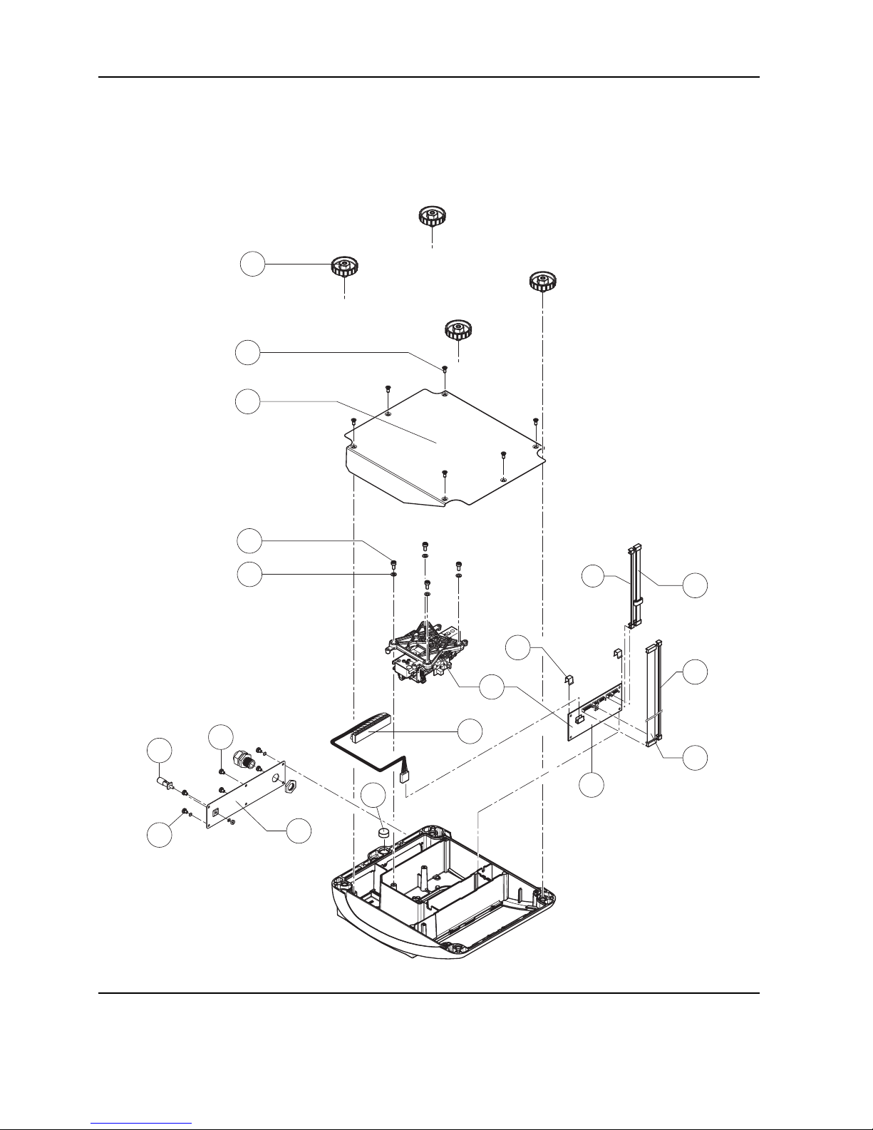
1.4 Viper RT terminal
1
3
5
4
26
27
29
18
2
28
6
9
8
16
31
7
17
11
12
10
13
32b
32a
9
8
16
31
7a
17
10
13
15 a
12
9
8
16
31
7
17
10
13
14 a
12
19
20
22
21
24
23
30
30
30
14 b
24
25
USB option Ethernet option
Page 85

Service Manual 21203788C 09/03 4-9
Viper M, L, D and T Scales/Viper RM, RL, RD and RT Terminals Section 4 Viper terminals
Item Quantity Designation Part no.
1 1 base plate with seal attached 21255118
2 4 rubber foot 00200068
3 8 countersunk screw M4 x 8 Torx T20 *
4 1 AC adapter 10W USA/Japan version 21255102
5 1 adhesive tape for AC adapter 21203184
6 1 seal for terminal rear panel 21255012
71 standard: connector plate for 3 x RS232C/PS2/load cell
1)
22010040
7a 1 option: connector plate for 2 x RS232C/Ethernet/PS2/load cell 22010042
8 1 countersunk screw M4 x 12 Torx T20 *
9 5 fillister head screw M4 x 8 Torx T20 *
Standard interfaces:
10 1 RS232C interface IP65 with cable (soldered)
2)
21203717
11 1 board with 2x RS232C IP65 (requires connecting cable item 12) 21255081
12 1 connecting cable for 2 RS interfaces 21203490
13 1 PS2 cable 18.1"/460mm (keyboard connection) 21204107
14 USB option (upgrade kit see chapter 4.2.2)
14a 1 board USB option (1 Sub-D socket for RS232C / 1 Sub-D connector for USB)
3)
21204114
14b 1 USB cable (with Sub-D and USB type B sockets) 21204031
15 1 Ethernet option (requires connector plate item 7a) (upgrade kit see chapter 4.2.3):
15a: 1 board Ethernet option (1x RS232C /1 x Ethernet RJ45)
3)
21204027
16 4 dust cover for interfaces 11101560
17 1 dust cover for PS2 interface 22010058
18 1 keypad overlay Viper RT 22010049
19 1 numeric keypad membrane (25 keys) (always order together with item 18) 21203501
20 1 display mounting plate RT/SC (always order together with items 18 and 19) 21255043
21 1 spacer plate 21255046
22 1 LCD module 240 x 64 dots CCFL 21203515
23 2 Torx oval head tapping screw 2.9 x 13 *
24 1 digital board Viper T/RT (incl. soldered FLASH Memory chip with software) 21203996
25 5 fillister head screw M3 x 6 Torx T10 *
26 1 analog board 7k 21255054
27 1 fastening clamp for analog board * 21203166
28 1 EMC clamp for analog board 22007948
29 1 A/D cable 300 mm 21203167
continues on next page
Page 86

4-10 09/03 Service Manual 21203788C
Section 4 Viper terminals Viper M, L, D and T Scales/Viper RM, RL, RD and RT Terminals
Viper RT terminal (continued)
1
3
5
4
26
27
29
18
2
28
6
9
8
16
31
7
17
11
12
10
13
32b
32a
9
8
16
31
7a
17
10
13
15 a
12
9
8
16
31
7
17
10
13
14 a
12
19
20
22
21
24
23
30
30
30
14 b
24
25
USB option Ethernet option
Page 87

Service Manual 21203788C 09/03 4-11
Viper M, L, D and T Scales/Viper RM, RL, RD and RT Terminals Section 4 Viper terminals
30 8 screw lock *
31 1 load cell connection cable with Sub D-socket and plug for analog board
1)
22010055
32 – 9-pin Sub-D connector (for connecting the load cell to the terminal): ––––––
32a 1 Sub-D standard housing (dismantled) 22007870
32b 1 pin base 22007869
* Included in small parts set (section 3).
1)
Is also used with analog interface option and USB option.
2)
If an analog interface option is built into the OptionPac (see chapter 2), a second cable of this type is used to connect the
analog interface option board to the connector plate of the terminal (item 7 above).
3)
replaces the standard interface board (2 x RS232C), part no. 21255081. The standard connecting cable (part no.
21203490) can be used with the optional interface board. However, if an analog interface option is present the “ETH/USB
option” cable (part no. 22010154) must be used instead of the standard connecting cable (part no. 21203490). This cable
is included in the respective upgrade kits (see chapters 4.2.2 and 4.2.3).
Page 88

4-12 09/03 Service Manual 21203788C
Section 4 Viper terminals Viper M, L, D and T Scales/Viper RM, RL, RD and RT Terminals
2 OptionPac
1
3
7
8
9
10
11
12
17
16
15
14
4
5
13
6
2
18
19
Page 89

Service Manual 21203788C 09/03 4-13
Viper M, L, D and T Scales/Viper RM, RL, RD and RT Terminals Section 4 Viper terminals
Item Quantity Designation Part no.
1 1 base plate with seal attached 21255118
2 4 rubber foot 00200068
3 8 countersunk screw M4 x 8 Torx T20 *
4 4 fillister head screw M5 x 12 *
5 1 charging circuit board for battery 21255052
6 2 fastening clamp for charging circuit board * 21203166
7 1 connecting cable charging circuit – analog board 21203233
8 1 battery cable 21203231
9 1 battery 12V/2.2Ah (always order together with item 10) 21203232
10 2 adhesive tape for battery 21255260
11 1 seal for back panel OptionPac 21255013
12 1 back panel without openings 21255003
13 1 analog interface option board (Viper RL, RD and RT only) 21203383
14 4 tapping screw M3 x 6 (Viper RL, RD and RT only) 21050008
15 1 EPROM with interface software for analog interface (Viper RL, RD and RT only)
EPROM for Viper RL and RD analog interface 21203915
EPROM for Viper RT analog interface 21255318
16 1 cable for analog option (Viper RL, RD and RT only) 21203604
17 1 seal (between OptionPac and Terminal) 21255011
18 5 fillister head screw M4 x 8 Torx T20 *
19 1 countersunk screw M4 x 10 Torx T20 *
* Included in small parts set (section 3)
Page 90

4-14 09/03 Service Manual 21203788C
Section 4 Viper terminals Viper M, L, D and T Scales/Viper RM, RL, RD and RT Terminals
3 Small parts set
The fasteners set comprises all the standard components (screws, washers. etc.) required for service work on Viper scales and
terminals.
Quantity Description Order No.
1 fasteners set: 21203404
20 countersunk Torx screw M3 x 8 –
20 countersunk Torx screw M3 x 10 –
20 countersunk Torx screw M6 x 30 –
50 countersunk Torx screw M4 x 10 –
10 countersunk Torx screw M4 x 12 –
20 button head Torx screw M3 x 6 –
30 button head Torx screw M4 x 12 –
30 button head Torx screw M5 x 12 –
20 wide flange washer 4.3 x 20 –
20 wide flange washer 5.3 x 20 –
20 countersunk Torx screw M6 x 16 –
20 spring clip –
50 raised cheese head Torx screw M4 x 6 –
10 screw lock –
10 Torx oval head tapping screw 2.9 x 13 –
Page 91

Service Manual 21203788C 09/03 4-15
Viper M, L, D and T Scales/Viper RM, RL, RD and RT Terminals Section 4 Viper terminals
4 Upgrade kits
Installed Viper RL, RD and RT terminals can be subsequently upgraded with upgrade kits. The respective kits contain all the
necessary parts.
4.1 Upgrade kits for Viper RM, RL and RD terminals
The following upgrade kits are exclusively designed for Viper RM, RL and RD terminals.
4.1.1 “Analog Interface Option Viper RL/RD” upgrade kit
This upgrade kit allows connection of a second, analog weighing platform to a Viper RL or RD terminal.
Quantity Designation Part no.
1 Upgrade kit “Analog Interface Option Viper RL/RD” comprising: 22010143
1 OptionPac cpl. 21255117
4 round head screw M5 x 12 Torx 22005232
5 round head screw M4 x 6 Torx 22003003
1 screw DIN7500 M4 x 10 Torx 22003002
1 back panel without openings 21255003
1 analog interface option board 21203383
EPROM with interface software RL/RD 21203915
1 cable for analog option 21203604
1 RS232C interface IP65 with cable (soldered) 21203717
4 tapping screw M3 x 6 21050008
1 connector plate for 3 interfaces (RS232C/load cell/analog interface option) 22010043
2 screw lock 21203570
1 Sub-D standard housing (dismantled) 22007870
1 pin base 22007869
1 dust cover for interfaces 11101560
1 flat ribbon cable clamp 21255122
1 type plate Viper Terminal (sticker) 22010059
1 additional plate (sticker with interface designation) 22010143
Drawings of spare parts see chapters 1 and 2.
Page 92

4-16 09/03 Service Manual 21203788C
Section 4 Viper terminals Viper M, L, D and T Scales/Viper RM, RL, RD and RT Terminals
4.1.2 “AccuPac Viper RM/RL/RD” upgrade kit
This upgrade kit enables the Viper RM, RL and RD terminals to be operated without being connected to the power supply.
Quantity Designation Part no.
1 Upgrade kit “AccuPac” comprising: 2210144
1 OptionPac cpl. 21255117
4 round head screw M5 x 12 Torx 22005232
5 round head screw M4 x 6 Torx 22003003
1 screw DIN7500 M4 x 10 Torx 22003002
1 back panel without openings 21255003
1 battery cable 21203231
2 adhesive tape for battery 21255260
1 battery 12V/2.2Ah 21203232
1 connecting cable charging circuit – analog board 21203233
2 fastening clamp for charging circuit board 21203166
1 charging circuit board for battery 21255052
1 flat ribbon cable clamp 21255122
Drawings of spare parts see chapter 2.
Page 93

Service Manual 21203788C 09/03 4-17
Viper M, L, D and T Scales/Viper RM, RL, RD and RT Terminals Section 4 Viper terminals
4.2 Upgrade kits for Viper RT terminal
The following upgrade kits are exclusively designed for the Viper RT terminal.
4.2.1 “Analog Interface Option Viper RT” upgrade kit
This upgrade kit allows connection of a second, analog weighing platform to a Viper RL or RD terminal.
Quantity Designation Part no.
1 Upgrade kit “Analog Interface Option Viper RT” comprising: 22010145
1 OptionPac cpl. 21255117
4 round head screw M5 x 12 Torx 22005232
5 round head screw M4 x 6 Torx 22003003
1 screw DIN7500 M4 x 10 Torx 22003002
1 back panel without openings 21255003
1 analog interface option board 21203383
EPROM with interface software RT 21255318
1 cable for analog option 21203604
2 RS232C interface IP65 with cable (soldered) 21203717
4 tapping screw M3 x 6 21050008
1 Sub-D standard housing (dismantled) 22007870
1 pin base 22007869
1 flat ribbon cable clamp 21255122
1 type plate Viper Terminal (sticker) 22010059
1 additional plate (sticker with interface designation) 22010145
Drawings of spare parts see chapters 1 and 2.
4.2.2 “USB Interface Viper RT” upgrade kit
This upgrade supplements replaces the existing RS232C interface “COM2” with a USB interface (Universal Serial Bus).
Quantity Designation Part no.
1 Upgrade kit “USB Interface Viper RT” comprising: 22010147
1 board USB option (slave) IP65 (Sub-D socket RS232C / Sub-D connector for USB) 21204114
1 CD-ROM with USB drivers for Microsoft Windows
®
22010158
1 USB cable (with Sub-D and USB type B sockets) 21204031
1 cable ETH/USB option (required only if analog interface option is present) 22010154
1 additional plate (sticker with interface designation) 22010147
Drawings of spare parts see chapter 1.4.
Page 94

4-18 09/03 Service Manual 21203788C
Section 4 Viper terminals Viper M, L, D and T Scales/Viper RM, RL, RD and RT Terminals
4.2.3 “Ethernet Interface Viper RT” upgrade kit
This upgrade supplements replaces the existing RS232C interface “COM2” with an Ethernet interface.
Quantity Designation Part no.
1 Upgrade kit “Ethernet Interface Viper RT” comprising: 22010148
1 connector plate for 2 x RS232C/Ethernet/PS2/load cell 22010042
1 spacer for Ethernet interface 22008017
1 hexagon nut M3 DIN934 22008019
1 washer M3 DIN125 22008020
1 board Ethernet option (1x RS232C /1 x Ethernet RJ45) 21204027
1 cable ETH/USB option (required only if analog interface option is present) 22010154
1 additional plate (sticker with interface designation) 22010148
Drawings of spare parts see chapter 1.4.
4.2.4 “AccuPac Viper RT” upgrade kit
This upgrade kit enables the Viper RT terminal to be operated without being connected to the power supply.
This upgrade kit is not yet available
4.3 Certification set for Viper terminals and scales
This upgrade kit enables an authorized W & M inspector to properly seal a Viper weighing system after certification.
Quantity Designation Part no.
1 Upgrade kit “Viper certification set ” comprising: 21203903
1 securing plate 21203485
1 type plate Viper Terminal (sticker) 22010059
3 capstan headed screw DIN404 00205949
Page 95

Contents Page
1 Important information....................................................................................................................... 5-2
1.1 Safety and environment...................................................................................................................... 5-2
1.2 Tools and working aids...................................................................................................................... 5-2
1.3 Work instructions .............................................................................................................................. 5-2
2 Replacing the keypad overlay ........................................................................................................... 5-3
3 Replacing the AC adapter ................................................................................................................. 5-3
4 Replacing the battery ....................................................................................................................... 5-3
5 Replacing the charging PCB.............................................................................................................. 5-4
6 Replacing the analog PCB ................................................................................................................ 5-4
7 Replacing the display mounting plate, display unit and digital PCB..................................................... 5-5
7.1 Preliminary work ............................................................................................................................... 5-5
7.2 Replacing the display mounting plate .................................................................................................. 5-5
7.3 Replacing the liquid crystal display (LCD) or the back-light unit .............................................................. 5-5
7.4 Replacing the digital PCB ................................................................................................................... 5-6
7.5 Final reassembly ............................................................................................................................... 5-6
8 Replacing the software (Viper M and L scales with strain gauge load cells only) ................................. 5-7
9 Replacing the load cell ..................................................................................................................... 5-8
9.1 Replacing a strain gauge load cell ...................................................................................................... 5-8
9.2 Replacing the MonoBloc load cell ....................................................................................................... 5-10
9.2.1 Replacing the MonoBloc load cell of scales with small platforms ............................................................ 5-10
9.2.2 Replacing the MonoBloc load cell of scales with large platforms ............................................................. 5-11
Section 5
Repair of Viper scales
Page 96

5-2 09/03 Service Manual 21203788C
Section 5 Repair of Viper scales Viper M, L, D and T Scales/Viper RM, RL, RD and RT Terminals
1 Important information
This section describes how to change individual components of the Viper scales. When doing this, please refer to the exploded
view drawings and spare parts lists in sections 2 and 3. Important: After replacing components, a functional check of the scale
must always be carried out.
1.1 Safety and environment
The following instructions must be observed for all repairs:
– Disconnect the scale from the power supply before starting repair work!
– The scale contains electronic components which can be damaged by electro-
static discharges. You must therefore always wear a grounded wriststrap
when performing repair work! Grounded wriststraps can be purchased from
specialist electronics dealers.
– Defective components must be disposed of according to the instructions in
section 1!
• Servicing work in explosion hazard zones is strictly prohibited. Ignition power
could inadvertently be generated, causing an explosion. Servicing work should
therefore only be undertaken in secure areas. The location in which the scale
is installed must be declared by the system operator to be safe for the duration of
the repair work. If no such declaration is available, the scale must be switched off
and disconnected from the power supply and moved to a safe area.
• The scales can also be disconnected and reconnected to the power supply in
potentially explosive environments provided that the power supply has first been
switched off.
1.2 Tools and working aids
– Screwdrivers: Torx T10, T20, T25, and T30; Phillips 5 mm; flat type size 0 and 4
– Torque wrench up to 10 Nm
– Wrench heads Torx T25, T30, and hex 17 mm
– Open-end wrench, size 20
– Feeler gauge
– Carpet knife (“cutter”)
– Grounded wriststrap (as protection against electrostatic discharges)
– Weights of class M1 or F1
1.3 Work instructions
Take great care when inserting and tightening screws into holes tapped directly into the aluminum casting: After inserting the
screw, always turn it first about 1 turn counterclockwise until it engages in the existing thread, and only then screw it tight! Do
not tighten the screw too much, since this may damage the thread in the aluminum casting!
Page 97

Service Manual 21203788C 09/03 5-3
Viper M, L, D and T Scales/Viper RM, RL, RD and RT Terminals Section 5 Repair of Viper scales
2 Replacing the keypad overlay
Notes for Viper explosion proof (Ex) scales: To prevent electrostatic charging of the keypad overlay, the display
insert has a metallized coating. Since this coating is detached when the keypad overlay is removed, the keypad
overlay on these scales can only be replaced in conjunction with the display insert, the specification plate and the
“Ex” sticker (see chapter 7).
• Lift up the defective keypad overlay (if necessary carefully prying it up with a knife) and gently peel it off the scale. Note: take
care that the specification label is not damaged when the membrane is removed!
• Carefully clean display mounting plate, keypad membrane (Viper T) and window (removing all traces of adhesive).
• Make sure that the specification label is in its correct position (must be visible through the window in the keypad overlay),
then peel off the protective film from the new membrane and carefully affix the latter to the display mounting plate. Press the
keypad overlay down uniformly.
3 Replacing the AC adapter
Note: The AC adapter has a fuse as overcurrent protection. For safety reasons this fuse cannot be replaced, and the AC
adapter must therefore be replaced completely if the fuse blows. This applies only to scales that are connected directly to
the AC power line (without rechargeable battery and external AC adapter).
• Unscrew the adjustable feet and remove them.
• Undo the bottom plate retaining screws, removing them and the plate itself.
• Disconnect the AC adapter cable from the analog PCB.
• Remove the AC adapter (held on by an adhesive patch) from the wall of the housing . If necessary, carefully insert a flat blade
(knife or screwdriver) between adapter and housing and pry them apart. Remove all traces of adhesive from the housing.
• Undo the 4 screws holding the blanking plate in place (rear panel of scale) and remove the plate.
• Slide the AC adapter power cord grommet out of the blanking plate. Remove the AC adapter from the scale.
• Place the new AC adapter in the scale and fix it in place with the adhesive patch.
• Locate the power cord grommet (with its closed side facing up!) in the center of the blanking plate slot, then press the
grommet down thoroughly. This requires a fair amount of force which is intended as it ensures proper IP protection. Caution:
Never use a hammer or similar tool for pushing the grommet into place because this may damage the wires! Once the
grommet is properly located in the slot you may fasten the blanking plate.
Note for scales with IP65 protection: Check that the seal of the blanking plate is still correctly fastened to the housing. If it
is not, the seal must be replaced as follows: Remove the existing seal from the housing so as to leave no trace. Clean and
degrease the surface to which it was fastened. Carefully affix the new seal to the housing in exactly the right position.
• Plug the AC adapter output cable onto the analog PCB, then replace the bottom plate and the adjustable feet.
4 Replacing the battery
Note: This procedure is only required for scales that have a built-in rechargeable battery and an external AC adapter.
• Unscrew the adjustable feed screws and remove them.
• Undo the bottom plate retaining screws, removing them and the plate itself.
• Undo the screws holding the RS connector plate in place (rear panel of scale) and remove the plate.
• Slide the charging PCB out from the guide and remove both plugs on the PCB (connection cable to battery or analog PCB).
• Remove the battery from the wall of the housing (held in place by the adhesive strip). If necessary, carefully insert a flat blade
(knife or screwdriver) between the battery and housing and pry them apart. Remove all traces of adhesive from the housing.
• Remove the battery from the scale and disconnect the cable to the charging PCB.
Page 98

5-4 09/03 Service Manual 21203788C
Section 5 Repair of Viper scales Viper M, L, D and T Scales/Viper RM, RL, RD and RT Terminals
• Plug the cable to the charging PCB into the new battery (+ = red cable, – = blue cable).
• Attach the adhesive patch to the wall of the housing, remove its protective foil, place the battery in the scale and press it
against the wall of the housing.
• Attach both plugs with connectors to the charging PCB and slide the PCB back it into the guide.
• Replace the RS connector plate and secure with the screws.
Note for scales with IP65 protection: Check that the seal of the RS connector plate is still correctly fastened to the housing.
If it is not, the seal must be replaced as follows: Remove the existing seal from the housing so as to leave no trace. Clean and
degrease the surface to which it was fastened. Carefully affix the new seal to the housing in exactly the right position.
• Check the connections of all cables: The cables must lie in the correct slots of the housing, to ensure they are not pinched by
the bottom plate.
• Replace the bottom plate and the adjustable feet.
5 Replacing the charging PCB
Note: This procedure is only required for scales with a built-in battery. Before fitting the new charging PCB, check that the
correct AC adapter for battery operation is present (see spare parts lists in sections 2 and 3). If not, the AC adapter must also
be replaced.
• Undo the screws holding the rear panel of the scale and remove the panel.
• Slide the PCB out from the guide and remove both plugs on the PCB (connection cable to battery and analog PCB).
• Attach both plugs with connectors to the (new) charging PCB and slide it into the guide.
• Replace the rear panel and secure with the 4 screws.
Check that the seal of the rear panel is still correctly fastened to the housing. If it is not, the seal must be replaced as follows:
Remove the existing seal from the housing so as to leave no trace. Clean and degrease the surface to which it was fastened.
Carefully affix the new seal to the housing in exactly the right position.
6 Replacing the analog PCB
Note: For scales with MonoBloc load cells the entire weighing module is usually replaced as its components (load cell and
analog PCB) are a matching set: The analog PCB contains all temperature compensation data of the load cell (TK data). If only
the analog PCB is to be replaced, then please note the following: A printout with the TK data of the load cell should be included
in every scale. If this is not the case then this data must be printed out before the analog PCB is replaced. Otherwise the TK data
cannot be loaded into the new analog PCB (see section 7)!
Viper Ex scales also require the PSU power supply unit in order to print out and restore TK data. If this is not available, the entire
weighing module must be replaced.
• Unscrew the adjustable feet and remove them.
• Undo the bottom plate retaining screws, removing them and the plate itself.
• Disconnect load cell cable, connecting cable to the digital PCB and the AC adapter output cable from the analog PCB.
• Pull off the two spring clips from the analog PCB and remove it.
• Fit the new analog PCB and fix it in place with the spring clips.
• Connect the load cell cable, the A/D cable from the digital PCB and the AC adapter output cable to the analog PCB.
• Replace the bottom plate and the adjustable feet.
Note
: After replacing the analog PCB all scale data plus all user settings must be re-entered (see section 5)! The scale must first
be calibrated and a linearization and recalibration carried out as required. For scales with MonoBloc load cells the temperature
compensation data of the load cell must first be loaded into the new analog PCB via computer (see section 7).
Page 99

Service Manual 21203788C 09/03 5-5
Viper M, L, D and T Scales/Viper RM, RL, RD and RT Terminals Section 5 Repair of Viper scales
7 Replacing the display mounting plate, display unit and digital PCB
The display mounting plate is located underneath the keypad overlay and is located in the scale housing by 6 snaps. The
display unit comprises the digital PCB, the liquid crystal display (LCD) and the back-light unit (on the Viper T the lighting is
integrated into the LCD module). It is held in place on the mounting plate by snaps and one screw. The digital PCB is connected
to the analog PCB and the RS232C interface by two ribbon cables (on Viper D and T scales there is an additional cable for the
keypad).
7.1 Preliminary work
• Unscrew the adjustable feet and remove them.
• Undo the bottom plate retaining screws, removing them and the plate itself.
• Viper M, L und D: Remove both EMC clamps. Undo the retaining screw which fastens the display unit to the mounting plate.
Pull back the two front cantilever snaps holding the display unit to release it, raise the front edge of the display unit and
withdraw it from the rear snaps. Disconnect the RS232 cable and the connecting cable to the analog PCB from the digital PCB
(on Viper D scales also remove the cable of the numeric keypad membrane). Remove the display unit.
• Viper T: Unfasten the 5 screws holding the digital PCB to the scale housing. Detach all cable connections from the digital PCB
and PCB. Unfasten the mounting screw fixing the LCD module to the display insert. Push the front retaining clips on the LCD
module forward slightly, swivel the module up and pull it out from the rear brackets.
7.2 Replacing the display mounting plate
Note: In order to replace the display mounting plate, the keypad overlay must be removed. This cannot be reused and must also
be replaced. On Viper D and T scales the pressure sensitive membrane for the keypad must be replaced at the same time as it
cannot be removed from the display mounting plate without damage.
• Remove keypad overlay (chapter 2).
• Push the 3 cantilever snaps at the front edge of the display mounting plate inwards to release the plate and remove it to the
front.
• Insert the new display mounting plate into the aperture so that it clicks into place. Note: On Viper Ex scales the window on
the display insert is covered with a conductive, transparent film. Do not touch this film otherwise fingerprints will remain
visible. If necessary clean the film by wiping it gently with a soft antistatic cloth.
• Viper D and T scales only: peel off the protective film from the new keypad membrane and carefully affix the latter to the
display mounting plate.
• Apply the new self-adhesive keypad overlay (chapter 2).
7.3 Replacing the liquid crystal display (LCD) or the back-light unit
The following steps apply only to Viper M, L and D scales. On Viper T scales the entire LCD module must be replaced
where applicable (see chapter 7.1 for dismantling instructions).
• Place the display unit with the digital PCB downwards on a conductive CMOS film.
• Disconnect the backlighting ribbon cable from the digital PCB.
• Carefully insert a flat blade screwdriver (size 4) between the digital PCB and the back-light unit immediately adjacent to the
connectors.
• With the screwdriver pry the liquid crystal display and the back-light unit out of the socket strips. When doing this, lever the
shaft of the screwdriver against the edge of the digital PCB. Never lever the tip of the screwdriver against the surface of the
Page 100

5-6 09/03 Service Manual 21203788C
Section 5 Repair of Viper scales Viper M, L, D and T Scales/Viper RM, RL, RD and RT Terminals
PCB, as this could damage the latter!
• Remove the upper protective cover of the back-light unit.
• Place the new back-light unit onto the digital PCB (it snaps into place on the board).
• Remove the upper and lower protective cover of the LCD.
• Carefully place the LCD onto the back-light unit and ensure that the connector pins are correctly aligned with the socket strips.
When correctly positioned, the ends of the LCD and back-light unit are flush. Use a flat object such as a ruler to exert a
uniform pressure on the LCD and gently push it home.
• Push the back-light unit ribbon cable connector onto the digital PCB pins.
7.4 Replacing the digital PCB
The following steps apply only to Viper M, L and D scales. On Viper T scales the digital PCB and the LCD are separate units
that can be replaced individually (see section 7.1 for dismantling instructions).
• Remove the LCD and back-light unit as described in the previous chapter.
• Remove the EPROM from its socket (Viper M and L scales with strain gauge load cells only). With Viper D scales and all
scales with MonoBolc load cells the entire digital PCB inlcuding the soldered Flash Memory chip must be replaced if
downloading the scale software via a computer fails for any reason (see section 7).
• Fit LCD and back-light unit onto the new digital PCB (chapter 7.3). Fit the EPROM (Viper M and L scales with strain gauge
load cells only); see the notes in chapter 8.
7.5 Final reassembly
• Connect the RS232 cable and the cable from the analog PCB to the digital PCB (on Viper D scales also connect the cable of
the numeric keypad membrane).
• Engage the display unit or the LCD module (Viper T) under the rear snaps of the display mounting plate and then lower its
front edge until it snaps into place. Fit the retaining screw.
Caution: On the Viper M the LC display is only held in the connector strip on one side. Because of this, for assembly the PCB,
the display, and the backlighting must be held together with the hand, otherwise the backlighting may come out of the drilled
holes in the PCB and be displaced!
• Install both EMC clamps (does not apply to Viper T).
• Viper T scales only: Attach all cables to the digital PCB and secure the board to the scale housing with the 5 screws.
• Replace the bottom plate and adjustable feet.
 Loading...