

Page 1
Operator Manual
METTLER TOLEDO
Viper EX M and Viper EX M MB Scales
On
O
ff
Zero
Tare
Print
Units
Clear
C
Page 2
Overview of your Viper EX M / Viper EX M MB scale
Rear view Scale specifications
Overview
Display
Keypad
O
n
Off
Zero
Tare
Print
Units
Clear
C
On
Off
Zero Tare Print
Units Clear
C
Max: 6 kg d = 0.001 kg
Max: 12 lb d = 0.002 lb
1
2
3
5
7
91012
13 14
15
17
18 19 20 21
22
23
24252627
28 29
4
6
8
kg
tbz
P
CS
NET
12
C
om
16
11
Page 3

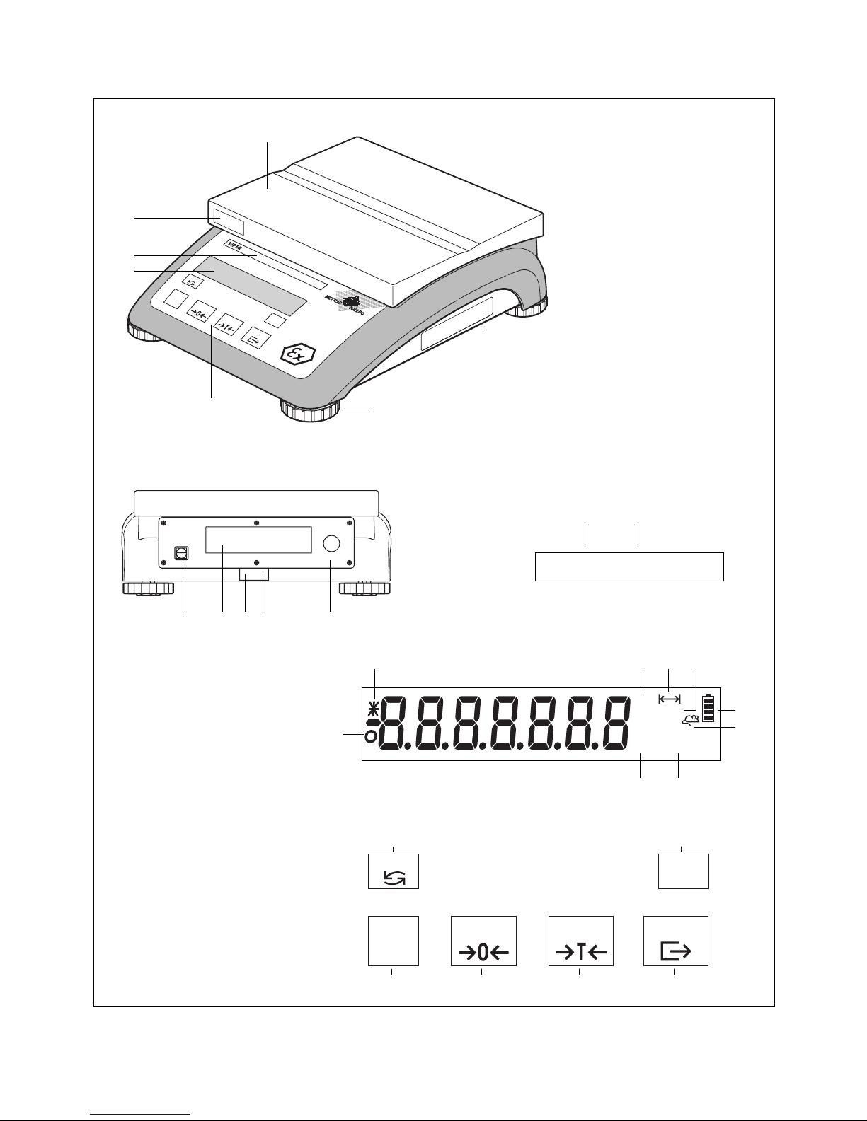
Overview
1 Keypad
2 Display
3 Scale specifications (see detailed illustration)
4 “MonoBloc” label (if applicable)
5 Platter (6lb version with small platter and draft shield)
6 Ex rating plate
7 Leveling feet
Rear view
8 Opening for cable gland
– power cable from PSUx power unit
– power/data cable from PSU power unit
9 Level indicator
10 Hole for antitheft device (accessory)
11 Type plate/certification plate
12 Grounding screw
Scale specifications (adhesive label)
13 Maximum load (in kg and lb)
14 Readability (display increment, in kg and lb)
Display
15 Unit for piece-counting (has no function)
16 Weighing units
17 Stability detector
18 Information mode indicator (has no function)
19 Data transfer (lights up while data is transmitted or
received via the interface)
20 Weighing range (has no function)
21 Net weight symbol
22 Internal battery charge status (has no function)
23 “Dynamic weighing” indicator (has no function)
Keypad
24 Transmits the weighing result to a connected device
(computer, printer, etc.) via the interface. If held down,
calls up the setup mode, and when working in setup,
functions as the “Yes” key to accept an option.
25 Tares the weighing container on the scale and sets the
display to zero. When working in setup, this key is
used as the “No” key to reject an option.
26 Sets the display to zero. When working in setup, this
key can be used to navigate backward. Each time the
key is pressed, the previous setup item is shown.
27 Switches the balance on and off. This key does not
function while working in setup mode.
28 Switches between the two weighing units specified in
setup.
29 Clears the current tare weight. When working in setup,
this key can be used to jump to the end of the setup for
rapid exit from the setup mode.
Page 4

Contents
4
Contents
1 Setting up the scale ....................................................................................................................................... 6
1.1 Unpacking and checking the delivered items ...................................................................................................... 6
1.2 Safety and environment.................................................................................................................................... 6
1.3 Selecting a location and leveling the scale ......................................................................................................... 7
1.4 Connecting the power supply and grounding cable ............................................................................................. 8
2 Weighing ....................................................................................................................................................... 9
2.1 Switching on/off and setting to zero ...................................................................................................................9
2.2 Simple weighing ............................................................................................................................................. 9
2.3 Weighing with tare ........................................................................................................................................ 10
2.4 Taring options............................................................................................................................................... 11
2.4.1 Multiple taring ............................................................................................................................................... 11
2.4.2 Automatic taring ............................................................................................................................................ 11
2.4.3 Automatic tare clearance ................................................................................................................................11
2.5 Recording the weighing result .........................................................................................................................11
3 Setup .......................................................................................................................................................... 12
3.1 Calling up the setup mode and entering the password ....................................................................................... 12
3.2 Setup structure ..............................................................................................................................................12
3.3 Working with the setup mode ......................................................................................................................... 13
3.4 Scale settings (“SCALE” block)........................................................................................................................ 15
3.4.1 Selecting the weighing units (“Units”) .............................................................................................................. 15
3.4.2 Settings for taring (“Tare”) ..............................................................................................................................16
3.4.3 Settings for zeroing (“Zero”)............................................................................................................................ 17
3.4.4 Adaptation to surrounding conditions (“Filter”) .................................................................................................. 18
3.4.5 Resetting the scale settings to the factory settings (“Scale Reset”) ....................................................................... 18
3.5 Scale settings (“TERMINAL” block) .................................................................................................................. 18
3.5.1 Settings for the display (“Device”) ................................................................................................................... 19
3.5.2 Settings for authorizing access to the setup mode (“Access”) ............................................................................. 19
3.6 Settings for the interface (“COMMUNICATION” block) ......................................................................................... 20
3.6.1 Selecting the communication mode (“Mode”) ................................................................................................... 21
3.6.2 Setting the communication parameters (“Parameters”) ...................................................................................... 22
3.6.3 Settings for the printed reports, or tickets (“Format”) .......................................................................................... 23
3.6.4 Settings for data transfer (“Control”) ................................................................................................................ 24
3.6.5 Resetting the communication settings (“Communication Reset”) ......................................................................... 24
3.7 Printing out the settings (“DIAGNOSTICS” block) ............................................................................................... 25
3.8 Saving the settings and quitting the setup mode (“END” block) ........................................................................... 26
3.9 Setup overview.............................................................................................................................................. 27
Page 5

Contents
5
4 Additional important information................................................................................................................... 28
4.1 SICS interface commmands ............................................................................................................................ 28
4.1.1 Preconditions for communication between scale and computer .......................................................................... 28
4.1.2 SICS standard commands supported by Viper................................................................................................... 28
4.2 “TOLEDO Continuous” mode ...........................................................................................................................29
4.2.1 “TOLEDO Continuous” output format ................................................................................................................29
4.2.2 “TOLEDO Continuous” commands ................................................................................................................... 30
4.3 Warning and error messages.......................................................................................................................... 30
4.4 Cleaning instructions ..................................................................................................................................... 31
5 Technical data and accessories..................................................................................................................... 32
5.1 Technical data .............................................................................................................................................. 32
5.2 Dimensions ..................................................................................................................................................33
5.3 Interface specifications ...................................................................................................................................34
5.4 Accessories .................................................................................................................................................. 34
5.5 Standards and directives ................................................................................................................................34
5.5.1 Safety regulations .......................................................................................................................................... 34
5.5.2 FCC Compliance ........................................................................................................................................... 35
5.5.3 Canadian Radio Interference Regulations ......................................................................................................... 35
5.6 Control Drawing Viper Ex 21204099............................................................................................................... 36
5.7 Installation Drawing Viper Ex Canada 21204100 ............................................................................................. 37
Page 6
Chapter 1: Setting up the scale
6
1 Setting up the scale
Please read these operating instructions carefully and follow them exactly! If you find that any items are missing or incorrect, or if
you have any other problems with your scale, please contact your authorized METTLER TOLEDO representative.
1.1 Unpacking and checking the delivered items
Remove the scale and accessories from the packaging. Check that all items have been delivered. The package should include:
– Viper scale
– Platter (and draft shield on 6lb version)
– Operating instructions (this document)
– Labels for noting the weighing range and readability after setting
– Special accessories per packing list (if applicable)
1.2 Safety and environment
To ensure safe, environmentally compatible operation of your scale, please observe the following:
The scale is designed for operation in hazardous areas Class I, Division 1, Groups A, B, C, D. However, for
this purpose the scale must be connected to a certified METTLER TOLEDO power supply unit:
– PSUx power supply unit (if not using the data interface)
– PSU power supply unit (if using the data interface)
The installation instructions for the respective power supply unit must always be observed and followed.
The regulations for operating equipment in hazardous areas must always be observed and followed.
Never undo the fastening screws of the load plate support under the platter!
Never insert a rigid object under the load plate support when the platter is removed.
Do not open the scale by undoing the screws in the base.
Use only the recommended accessories and peripherals.
Treat the scale carefully. It is a precision instrument. Avoid knocking the platter or placing excessively heavy
loads on it.
Important if the Viper scale will be used in food processing areas: Those parts of the scale which may come
into contact with food have a smooth surface and are easy to clean. The materials used do not shatter and
contain no harmful substances.
Because of the danger of static charge, a protective cover may only be used if it is made from anti-static
material.
When disposing of the scale, observe the applicable environmental regulations.
Page 7
Chapter 1: Setting up the scale
7
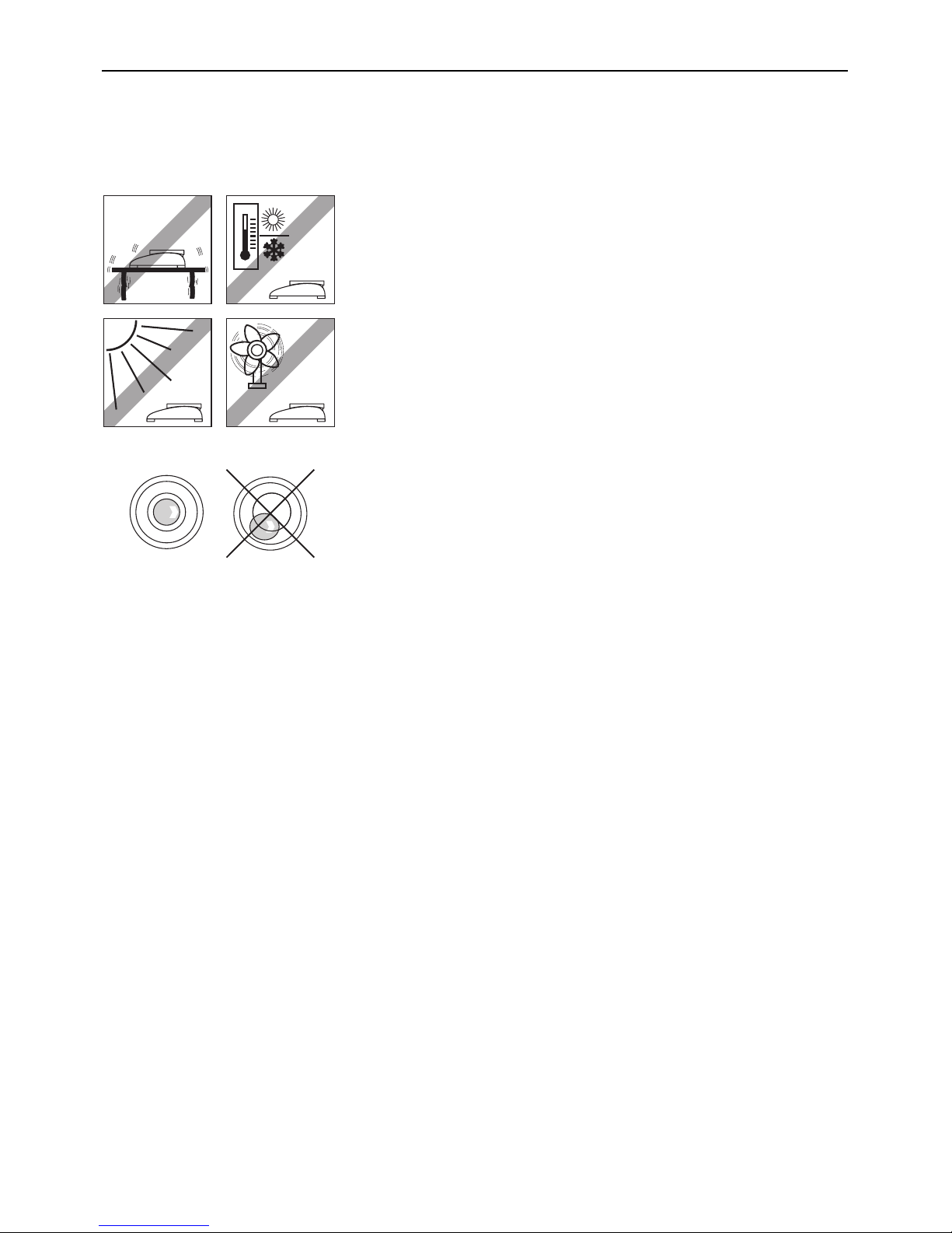
1.3 Selecting a location and leveling the scale
Choosing the proper location for your scale will guarantee high weighing accuracy!
Choose a stable, vibration-free, flat surface (this is especially important for highresolution scales and balances with METTLER TOLEDO MonoBloc technology). This
surface must be able to safely bear the weight of the fully loaded scale.
Pay attention to environmental conditions.
Avoid:
– direct sunlight
– strong drafts (e.g. from fans or air conditioning)
– excessive temperature fluctuations
– the use of radio equipment in close proximity to the scale.
Adjust the scale horizontally by turning the leveling feet. If there is a level indicator, the
air bubble must lie inside the inner circle.
Major changes of geographical location
Each scale is adjusted by the manufacturer for the local gravitational conditions (geo
value) of the geographical zone to which the instrument is shipped. If there is a major
change of geographical location, this adjustment must be corrected by a service
technician, or the scale must be readjusted. Certified scales must also be recertified in
accordance with applicable regulations for certification.
Page 8
Chapter 1: Setting up the scale
8
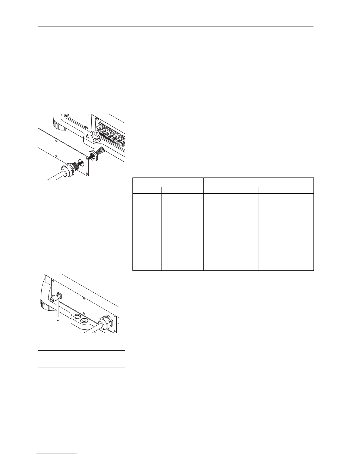
1.4 Connecting the power supply and grounding cable
To ensure protection against explosions, the scale may only be operated with either the PSUx or PSU power supply unit, and must
be connected to the building ground by a cable with a cross section of 1–4 mm2.
Important: When making the connection, always observe and follow the separate installation instructions for the PSUx or PSU power
supply unit respectively.
To connect the cable of the power supply unit and the grounding cable proceed as
follows:
Unscrew the screws in the back plate and remove the back plate.
Fasten the screwed connector on the blue cable of the power supply unit to the back plate
with the locking nut.
Connect the nine-core cable to the screw terminals of the scale according to the following
table.
Scale Power supply unit
No. Function PSUx PSU
1U1 white white
2 GND yellow yellow
3U2 green green
4 GND brown brown
5 Ubl gray black
6 TXD+ red red
7 TXD– blue blue
8 RXD– –– pink
9 RXD+ –– gray
10 NC black ––
11 NC pink ––
Replace the back plate and fasten it with the screws. When doing so, take care not to
trap any wires.
Using a cable with a cross section of 1–4 mm2 connect the grounding screw on the back
of the scale to the building ground. Make sure the grounding cable is correctly connected
to the scale and the building ground.
Powering up the scale initiates a display test in which all the segments and then the
software version are briefly displayed. Once the decimal zero appears in the display,
the scale is ready to operate.
For maximum possible precision, the scale must be adjusted/calibrateed by a service
technician after installing it. Note: Certified scales must be adjusted by an authorized
organization. Please consult your dealer.
=000
¬
Page 9
Chapter 2: Weighing
9
2Weighing
This chapter explains how you switch the scale on and off, adjust the zero setting, tare the scale, carry out weighings, and record
weighing results.
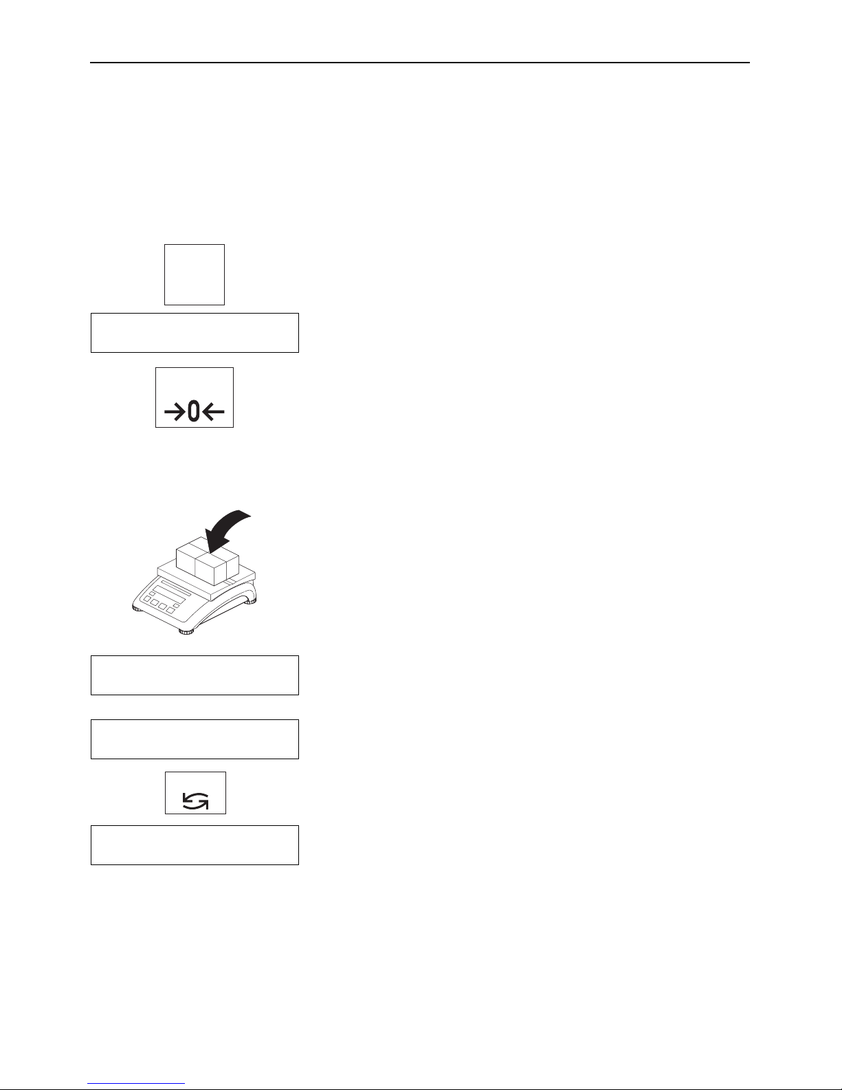
2.1 Switching on/off and setting to zero
You switch the scale on and off by pressing the «On/Off» key.
After it has been switched on, the scale carries out a display test. When the weight
display appears, the scale is ready for weighing and is automatically set to zero.
Note: If necessary, you can use the «Zero» key to set the scale to zero at any time.
On
Off
=000
¬
Zero
2.2 Simple weighing
Place the weighing sample on the platter.
Wait until the stability detector (small ring at left-hand edge of display) goes off and
then ...
... read the weighing result.
You can use the «Units» key at any time to switch between the two weight units
preselected in setup.
• (642
¬
(644
¬
Units
*921∆
Page 10
Chapter 2: Weighing
10
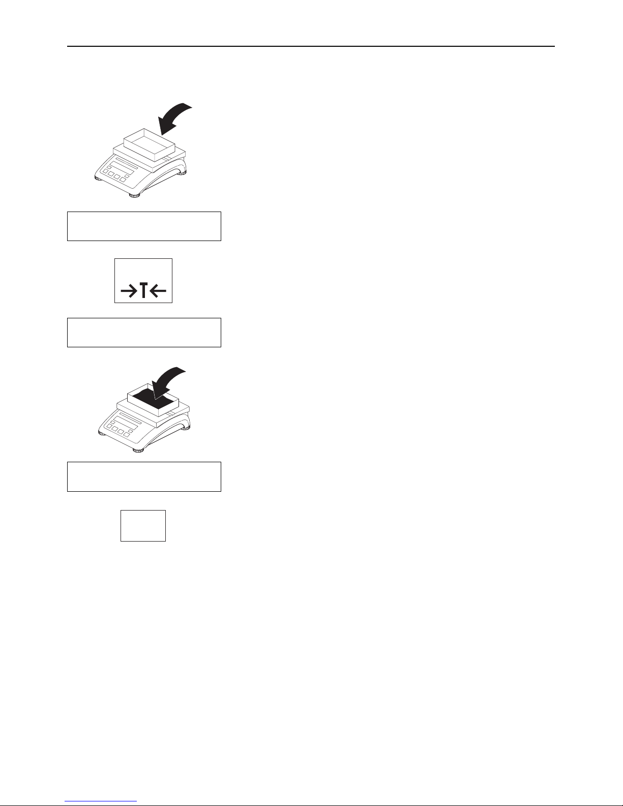
2.3 Weighing with tare
Place the empty weighing container or the packaging material on the platter.
The display shows the weight of the container on the pan.
Press the «Tare» key to tare the scale.
The zero display and the “NET” (net weight) symbol appear. Note: If the automatic taring
function has been activated in setup (Section 3.4.2), it is not necessary to press the
«Tare» key.
Place the weighing sample on the platter ...
... and read the result (net weight of the weighing sample).
When you have completed the weighing, press the «Clear» key to clear the weighing
result and the tare memory. The scale is now ready for the next weighment.
=223
¬
B/G
=000
¬
NET
ç653
¬
NET
Clear
C
Tare
Page 11

Chapter 2: Weighing
11
4.876 lb G
0.223 lb T
4.653 lb NET
2.4 Taring options
At the factory, the scale is set so that taring is carried out using the «Tare» key as described in the previous section. However, other
taring options can be activated in setup (Section 3.4.2); these are described below.
2.4.1 Multiple taring
If the “Chain tare” function is activated, you can re-tare the scale at any time by pressing the «Tare» key. Each time the key is pressed,
the value in the tare memory is overwritten with the current weight value. This allows you to place an additional weighing container
on the pan at any time and tare it. Note: On noncertified scales, this function is activated at the factory; on certified scales, this function
is not available.
If the “Chain tare” function has been switched off in setup, only one single taring is allowed for each weighing operation. If you
nevertheless attempt to tare the scale a second time, the error message “No” appears. You can only tare again after the current
weighing result has been cleared with the «Clear» key or the display has been reset to zero using the «Zero» key.
2.4.2 Automatic taring
If the “Autotare” function is activated, the scale automatically interprets the first weight placed on the pan as the tare weight. When
weighing is complete and all items have been removed from the platter, after a few seconds, the tare value is cleared and the scale
is ready for the next taring and weighment. Note: The “Autotare” function is turned off at the factory. On noncertified scales, it can
be activated in setup; on certified scales, this function is not available.
2.4.3 Automatic tare clearance
If this function is activated, the tare value is automatically cleared when the weighing container is removed from the platter, provided
that a weighment has previously been carried out. Note: At the factory, automatic tare clearance is turned off. This function can only
be activated in setup if the automatic taring function is turned off.
2.5 Recording the weighing result
Pressing the «Print» key transmits the current weighing result via the interface to the
peripheral device (printer, computer). At the factory the interface is configured for connection of a printer. Refer to Section 3.6 for information about configuring the interface.
The example on the left shows a record of a weighment with tare. “G” indicates the gross
weight, “T” the tare, and “NET” the net weight.
Page 12
Chapter 3: Setup
12
3 Setup
You can use the setup mode to change the settings of the scale and to activate functions. This makes it possible to adapt the scale
to your individual weighing needs. To prevent incorrect operation during day-to-day work, setup is reserved for the supervisor and
can only be accessed with a password (Exception: Parts of the “Terminal” block can be accessed by the user, see Section 3.5.2).
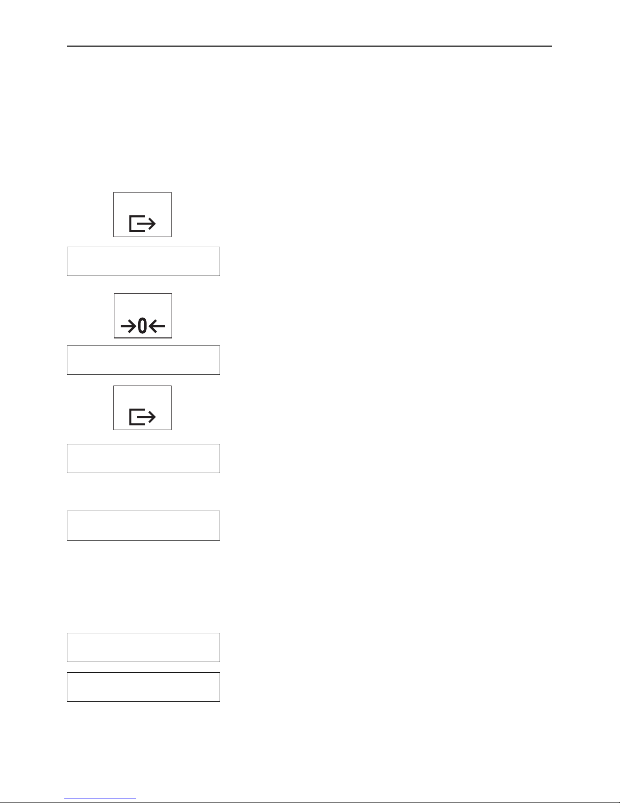
3.1 Calling up the setup mode and entering the password
Press the «Print» key and hold it down until ...
... the prompt to enter the password appears.
The password comprises a series of keystrokes. At the factory, the password for the
supervisor has been set to «Zero» «Zero» «Zero». We recommend you to replace this
password with one of your own as soon as possible (Section 3.5.2).
To call up the setup mode using the password set at the factory, briefly press the «Zero»
key three times.
Each keystroke you enter is shown in the display as a double horizontal dash.
Confirm the password with the «Print» key.
If you entered the password correctly, the first main block of the setup now appears.
Note:
– Enter the password as soon as you are prompted with “Code”; otherwise, the scale
returns to normal operation after a few seconds.
– If the password you entered is incorrect, an error message (“no”) appears, and
shortly after this you will be prompted to reenter the password.
– If you do not operate any key for approximately 3 minutes, the scale automatically
returns to weighing mode.
Zero
3x
CodE
≠≠≠
SCALE
- - no - - -
SCALE
3.2 Setup structure
The setup of the Viper scale is divided into 5 main blocks, each of which has a number of subblocks.
The first main block of the setup contains scale-specific settings (Section 3.4).
The second main block of the setup contains settings for the scale terminal and for
access authorizations (Section 3.5).
Print
tErMinL
Print
Page 13

Chapter 3: Setup
13
In the third main block, you can specify the settings for the interface (Section 3.6).
The fourth main block can be used to print out the settings (Section 3.7).
In the fifth main block, you can save your settings and quit the setup (Section 3.8).
You will find a complete overview of the setup mode in Section 3.9.
COMM
diAGnOS
End
3.3 Working with the setup mode
To work with the setup you use the following keys:
In the setup you use the «Print» key to confirm that you wish to accept a proposed option
(entry to a setup block or selection of a particular setting). This key has the meaning
“YES”.
You use the «Tare» key to reject a proposed option (entry to a setup block or selection
of a particular setting). This key has the meaning “NO”.
You use the «Zero» key to move back through the setup. Each time you press the key
it calls up the previous setup block.
The «Clear» key takes you directly to the end of the setup, where you can decide whether
you want to save the changes before you quit the setup mode.
Example
In the following example you want to turn off the backlighting of the display. This setting
is in the main block “Terminal” (the complete path to this setting is: Terminal –> Device
–> Backlight –> On/Off).
When you enter the setup, the first main block is displayed.
Now press the «Tare» (“No”) key repeatedly until the block appears in which you wish
to make a setting (in this example the main block “Terminal”).
Press the «Print» key. By doing so, you confirm that you want to enter the selected setup
block.
○○○○○○○○○○○○○○
Zero
Clear
C
SCALE
tErMinL
Print
Print
Tare
Tare
Page 14

Chapter 3: Setup
14
The first subblock of the “Terminal” appears.
Since the setting you want to change is in this block, press the «Print» (“Yes”) key.
The first subblock of the “Device” block appears in the display.
Since the desired setting is not in this block, press the «Tare» (“No”) key.
The second subblock of the “Device” setup is displayed. It is in this block that you make
the setting for the backlighting.
Press the «Print» key to enter this setup block.
The current setting for backlighting appears in the display. At the factory, backlighting
of the display is turned on (“On”).
Press the Tare» (“No”) key to switch the backlighting off.
The new setting is displayed.
Confirm the new setting (“OFF”) with the «Print» key. The backlighting is immediately
turned off.
Since you do not wish to make any more settings in setup at present, now press the
«Clear» key ...
... and you arrive at the last block in the setup.
Press the «Print» (“YES”) key to confirm that you wish to quit the setup mode.
You are now asked whether you wish to save the changed setting.
Press the «Print» (“Yes”) key to save the new setting and ...
... the scale returns to weighing mode. (If you do not wish to save the changed settings,
press the «Tare» (“No”) key instead, and the scale continues to use the former settings).
dEViCE
SLEEP
b-LiGht
On
OFF
End
SAVE ?
Clear
C
Print
Tare
Tare
Print
Print
Print
Print
Page 15

Chapter 3: Setup
15
3.4 Scale settings (“SCALE” block)
You use this block to make scale-specific settings. These include specifying weighing units, defining settings for taring and zeroing,
as well as special filter settings to adapt the scale to its environmental conditions.
The “SCALE” main block contains the following subblocks:
Selects the weighing units (Section 3.4.1)
Defines settings for taring (Section 3.4.2)
Defines settings for zeroing (Section 3.4.3)
Adapts the scale to environmental conditions (Section 3.4.4)
Resets the settings in the “SCALE” block to the factory settings (Section 3.4.5)
SCALE
3.4.1 Selecting the weighing units (“Units”)
In the “Units” block, you specify the weighing units with which your Viper scale should
operate. This block contains the following two subblocks:
In this subblock, you specify the weighing unit which should be displayed as standard.
The units available are shown at left. The factory setting is “lb”.
Note: On certified scales, the settings “g” and “oz” are not available.
In this subblock, you specify the second weighing unit which in weighing mode will be
displayed when you press the «Units» key.
The units available are the same as the standard weighing units, but with the additional
setting “OFF” (no second weighing unit). The factory setting is “kg”. On certified scales
the settings “g” and “oz” are also not available as second weighing units.
diSPLAY
lb
g
kg
oz
2nd
OFF
lb
g
kg
oz
UnitS
UnitS
tArE
2Ero
FiLtEr
SrESEt?
Page 16

Chapter 3: Setup
16
3.4.2 Settings for taring (“Tare”)
On
Pb - tArE
OFF
In the “Tare” block, you specify settings which control how your scale tares. This block
contains the following four subblocks:
In this subblock (“Pushbutton Tare”), you can activate or deactivate the «Tare» key:
The «Tare» key is active. This is the factory setting.
The «Tare» key is inactive; if it is pressed, no taring takes place.
In this subblock, you specify whether multiple taring (“Chain tare”) during a weighing
operation is allowed. Note: On certified scales, this block is not available!
The scale can be re-tared at any time. Each time the key is pressed, the value in the tare
memory is overwritten with the current weight value. This is the factory setting.
For each weighing operation, only one taring is allowed. Re-taring is only possible after
the current weighing result is cleared with the «Clear» key or the display is set to zero
with the «Zero» key.
In this subblock, you can turn the autotare function on or off.
The autotare function is turned off; taring is done manually using the «Tare» key. This
is the factory setting.
The autotare function is turned on. The scale automatically interprets the first weight
placed on the scale as the tare.
In this subblock, you specify whether the tare should be automatically cleared (“Auto
Clear Tare”). Note: This block is not avilable if the autotare function is active!
Automatic tare clearance is turned off. The current tare value is cleared with the «Clear»
key or by retaring. This is the factory setting.
The tare value is automatically cleared when the weighing container is removed from
the scale, provided that a weighing has been carried out.
On
ChAin
OFF
On
A-tArE
OFF
On
ÅCL - tr
OFF
tArE
Page 17

Chapter 3: Setup
17
OFF
3.4.3 Settings for zeroing (“Zero”)
In the “Zero” block, you specify the settings for zeroing the scale. This block contains
the following three subblocks:
In this subblock (“Autozero Mode”), you can turn automatic zeroing on and off and
specify how it operates. The autozero function automatically corrects the zero point of
the scale and thereby compensates for minor soiling of the platter. The following settings
are available:
Automatic zeroing is only active when no tare is present. This prevents small changes
in weight (e.g. when dispensing small quantities into a weighing container) from being
automatically compensated and the display being set to zero. This is the factory setting.
Automatic zeroing is always active.
Automatic zeroing is turned off.
In this subblock (“Auto Capture”), you can specify whether the scale should automa-
tically zero when it is turned on, and set the allowable zeroing range. If the weight on
the platter is within the selected range, the display is set to zero when the scale is
switched on; otherwise, an error message appears. The following settings are available:
Zeroing range at switch-on: ±10% of scale capacity. This is the factory setting.
Automatic zeroing of the scale at switch-on is deactivated.
Zeroing range at switch-on: ±2% of scale capacity.
In this subblock (“Pushbutton Zero”, not available on certified scales), you can use
the «Zero» key to set zeroing on and off and to set the allowable zero range. If the weight
on the platter is within the selected range, when the «Zero» key is pressed the display
is set to zero; otherwise, an error message appears. The following settings are possible:
Zeroing range: ±10% of scale capacity. This is the factory setting for noncertified
scales.
Zeroing range: +20% /–2 % of scale capacity.
Zeroing with the «Zero» key is deactivated.
Zeroing range: ±2% of scale capacity.
2Ero
OFF
GrOSS
GrS - nEt
A2M
2
$
10
$
A-CAPt
OFF
2
$
10
$
Pb - 2ErO
20
$
Page 18

Chapter 3: Setup
18
3.5 Scale settings (“TERMINAL” block)
In this main block, you can specify scale-specific settings. These include settings for the display, and for authorizing access to the
setup mode.
The “TERMINAL” main block contains the following subblocks:
Settings for the display (Section 3.5.1)
Settings for authorizing access to the setup mode (Section 3.5.2)
tErMinL
dEViCE
ACCESS
3.4.4 Adaptation to surrounding conditions (“Filter”)
You can use the “Filter” block to adapt your scale to the surrounding conditions (vibration, drafts). This block contains no subblocks; you arrive immediately at the following
settings:
Setting for normal surrounding conditions. This is the factory setting. The scale
operates at medium speed.
Setting for unstable surroundings. The scale operates more slowly than with the factory
setting, but is less sensitive to external disturbance.
Setting for very stable and stable surroundings. The scale operates very fast, but is
more sensitive to external disturbance.
FiLtEr
LO
MEd
hiGh
3.4.5 Resetting the scale settings to the factory settings (“Scale Reset”)
You can use the “S-Reset” (“Scale Reset”) block to reset all the settings in the “SCALE”
block to the factory settings.
To reset the settings, press the «Print» (“Yes”) key. If you do not wish to reset the
settings, press the «Tare» (“No”) key instead.
You are asked again whether you really want to reset the settings in the “SCALE” block.
If you want to reset, press the «Print» (“Yes”) key again. Otherwise, press the «Tare»
(“No”) key. This is your last chance to cancel the reset.
When you press the «Print» key as confirmation, all the settings in the “SCALE” block
are reset and the scale immediately operates with the factory settings.
SrESEt?
SurE?
Print
Print
Page 19

Chapter 3: Setup
19
3.5.1 Settings for the display (“Device”)
In the “Device” block, you can specify settings for the display. This block contains the
following two subblocks:
The setting in this subblock (“Sleep”) does not have any effect for Viper EX M and EX M
MB scales.
In this subblock (“Backlight”), you can switch the backlighting of the display on and
off:
Backlighting of the display is switched on. This is the factory setting.
Backlighting of the display is switched off.
OFF
SLEEP
dEViCE
On
OFF
b-LiGht
On
3.5.2 Settings for authorizing access to the setup mode (“Access”)
In the “Access” block, you specify authorizations and passwords for the setup mode.
This block contains the following two subblocks:
In this subblock (“User”), you can specify whether the operator should have access to
a part of the setup:
The operator has restricted access to the setup mode, specifically to the “TERMINAL”
block with the settings for energy-saving mode and backlighting. This is the factory
setting.
The operator has no access to the setup mode.
In this subblock (“Codes”), you can specify your own supervisor password for access
to the setup mode. Proceed as follows:
Call up the “Codes” block with the «Print» (“Yes”) key and ...
OFF
uSEr
ACCESS
On
COdES
SuPr - Cd
Page 20

Chapter 3: Setup
20
3.6 Settings for the interface (“COMMUNICATION” block)
Your scale has a built-in current loop interface which the PSU power supply unit converts into a user-selectable interface (refer to
the installation instructions for the PSU power supply unit). This main block is where you specify the settings for this interface.
The “COMMUNICATION” main block contains the following subblocks:
Selects the communication mode (Section 3.6.1)
Settings for the communication parameters (Section 3.6.2)
Settings for printed reports (Section 3.6.3)
Settings for data transmission (Section 3.6.4)
Resetting “COMMUNICATION” block to the factory settings (Section 3.6.5)
COMM
ModE
PArAMS
FOrMAt
COntrOL
CrESEt?
... you will be prompted to enter your new password. Enter the sequence of keystrokes
you wish to use as your password. You can use up to 6 keys. Important: The «Print»
key cannot be used in the password! Do not press this key, as it is used to terminate
input and confirm the new password!
Each keystroke is symbolized in the display by two double horizonal dashes. Confirm
the new password by pressing the «Print» (“Yes”) key.
You will now be prompted to enter the password again. Retype the new password and
confirm it again with the «Print» (“Yes”) key.
Definition of the password is now complete, and the next time you attempt to enter the
setup mode you will be asked for it. Important: Make a note of your password! If you
forget it, the service technician will have to define a new supervisor password before you
can use the setup again!
EntEr
≠≠≠≠≠≠
rEtYPE
Page 21

Chapter 3: Setup
21
3.6.1 Selecting the communication mode (“Mode”)
In the “Mode” block, you specify how your Viper scale should communicate through the
interface. This block contains the following two subblocks:
In this subblock, you specify the format in which data should be output through the
interface. This depends on the device you have connected to the interface.
The following settings are available:
Data output to a printer. This is the factory setting. Note: If you select this setting, a
further block with settings for the report printout is also available (Section 3.6.3).
The weight value is continuously transmitted through the interface in TOLEDO format
(“Continuous Weight”). This setting can be used to record weighing results on a computer.
The “TOLEDO Continuous Format” is explained in Chapter 4.2.
Bidirectional communication with an external device using MT-SICS commands. This
setting can be used to control the Viper scale from a computer. Refer to Section 4.1 for
information about the SICS interface commands.
In this block, you can make settings for the input line of the interface.
Important: This subblock is only available if the setting you selected in the preceding
“Output” block uses only the output line of the interface: These settings are “Print” or
“Continuous Weight”. With these settings, the input line can be used separately. (This
is not possible with the “SICS” setting, because this mode is bidirectional and therefore
also uses the input line of the interface). You can, for example, connect a printer but still
send commands from a PC to the scale through the same interface. (This requires a Tpiece which allows connection of the two devices and separates the input and output
lines of the interface).
The following settings are available:
The input line of the interface is used for the software handshake (Xon/Xoff protocol).
This setting must be used if the connected device requires a software handshake. This
is the factory setting.
The input line of the interface is not used.
The input side of the interface is used to receive commands in TOLEDO format (see
chapter 4.2.2).
OutPut
ModE
COnt - Wt
Print
SiCS
inPut
OFF
HOn.HOFF
COMMAnd
Page 22

Chapter 3: Setup
22
PAritY
ChECSuM
On
OFF
3.6.2 Setting the communication parameters (“Parameters”)
In the “Parameters” block, you specify the communication parameters for the interface.
Important: Make sure that these parameters are set to the same values on the external
device (printer, PC) which is connected to the scale. This block contains the following
three subblocks:
The “Baud” subblock is used to set the data transmission rate of the interface.
The available settings are shown at left.
The factory setting is 9600 baud.
The “Parity” subblock is used to specify the number of data bits and the parity.
The available settings are shown below:
7 data bits, even parity. This is the factory setting.
7 data bits, no parity.
8 data bits, no parity.
7 data bits, odd parity.
In the “Checksum” subblock, you specify whether the integrity of the values transmitted
through the interface should be verified by means of a checksum. Important: This sub-
block is only available if you have set the communication mode to “Continuous Weight”
(Section 3.6.1). The following settings are available:
Data validation turned off. This is the factory setting.
Data validation turned on.
bAud
PArANS
9600
300
600
2400
1200
4800
19200
7 nO P
7 EVEn
8 nO P
7 Odd
Page 23

Chapter 3: Setup
23
○○○○○○○
3.6.3 Settings for the printed reports, or tickets (“Format”)
In the “Format” block, you can specify the settings for printing reports.
Important: This block is only available if you have set the communication mode to
“Print” (Section 3.6.1). This block contains the following eight subblocks:
In the “Line Format” subblock, you specify how the printout should be formatted. The
following settings are available:
Multi-line printing. Each value in the report is printed on a separate line. This is the
factory setting.
Single-line printing. Several values (e.g. net weight, tare, and gross weight) are printed
on a single line.
A report can contain a maximum of 6 data fields. You use subblocks “Field 1” to “Field 6”
to specify which data should be printed on the report.
In each of the 6 blocks “Field 1” to “Field 6” the following settings are available:
The gross weight is printed on the report (factory setting for data field 1).
The tare weight is printed on the report (factory setting for data field 2).
The net weight is printed on the report (factory setting for data field 3).
The current weight value (“Display”) is printed on the report.
Instead of the value of the data field being printed on the report, blanks (“Spaces”) are
inserted in its place. This setting is useful if there is a particular data field you do not
wish to print out, but all the other fields should still be printed in the same positions.
The data field is not printed out (“Not Used”, factory setting for printing fields 4 to 6).
In contrast to the previous setting (“Spaces”) where blanks are inserted, printing of the
field is suppressed. The next field follows directly after the preceding field.
In this subblock (“Line Feed”), you can insert additional empty lines between the
reports, for example to leave space for adding handwritten notes to the printed values.
You can insert from 0 to 9 empty lines. The factory setting is “0” (no additional lines
are printed).
Ln FOr
FOrMAt
SinGLE
MuLti
FiELd - 1
FiELd - 6
○○○○
tArE
GrOSS
nEt
diSP
Not.uSEd
SPACES
Ln - FEEd
0
9
Page 24

Chapter 3: Setup
24
3.6.4 Settings for data transfer (“Control”)
In the “Control” block you specify the conditions under which data should be transmitted
through the interface. This block contains the following two subblocks:
In this subblock (“Auto Print”), you specify whether the data should be transmitted automatically or by pressing a key.
Automatic data transmission is switched off. The data is only transmitted when the
«Print» key is pressed. This is the factory setting.
The data is automatically transmitted as soon as the weighing result ist stable. Note:
This function is not available with early Viper M scales.
In this subblock (“Print Interlock”), you specify whether data can be transmitted only
once, or several times, during a single weighing operation. The following settings can
be selected:
An unlimited number of data transmissions is allowed per weighing operation. Data is
transmitted each time the «Print» key is pressed. This is the factory setting.
Data can only be transmitted again when the platter is completely empty or the «Clear»
key has been pressed.
A-Print
COntrOL
intrLOC
OFF
On
OFF
On
In the “C-Reset” (“Communication Reset”) block, you can reset all the settings in the
“COMMUNICATION” block to the factory settings.
To reset the settings, press the «Print» (“Yes”) key. If you do not wish to reset the settings,
press «Tare» (“No”) instead.
You are asked again whether you really want to reset the settings in the “COMMUNICATION” block.
If you want to reset, press the «Print» (“Yes”) key again. Otherwise press the «Tare»
(“No”) key. This is your last chance to cancel the reset.
When you press the «Print» key as confirmation, all the settings in the “COMMUNICATION” block are reset and the scale immediately operates with the factory settings.
CrESEt?
SurE?
3.6.5 Resetting the communication settings (“Communication Reset”)
Print
Print
Page 25

Chapter 3: Setup
25
3.7 Printing out the settings (“DIAGNOSTICS” block)
In this main block you can print out your settings on a printer.
The “DIAGNOSTICS” main block has only one subblock:
Print the settings.
To print out the settings on a printer, press the «Print» key.
Shown below is an example of a printout with the factory settings.
diAGnOS
LiSt
Print
Sw. ver M-1.00
SCALE
SNR : 99
MEtrOLO : nOnE
buiLd
CAP : 6.000 lb
rESOLu : 0.002 lb
GEO : 16
UNIT
DiSPLAy : lb
2nd : kg
tArE
Pb-tArE : On
ChAin : On
A-tArE : OFF
A.CL-tr : OFF
ZErO
AZM : GrOSS
A-CAPt : 10 %
Pb-ZErO : 10 %
FiLtEr : MEd
tErMinL
dEViCE
SLEEP : OFF
b-LiGht : On
ACCESS
uSEr : On
SuPEr : On
COMM
MOdE
OutPut : Print
inPut : XOn.XOFF
PArAMS
bAud : 9600
PArity : 8 no P
ChECSuM : OFF
FOrMAt
Ln FOr : MuLti
FiELd-1 : GrOSS
FiELd-2 : tArE
FiELd-3 : nEt
FiELd-4 : nOt.uSEd
FiELd-5 : nOt.uSEd
FiELd-6 : nOt.uSEd
Ln-FEEd : 0
COntrOL
A-Print : OFF
intrLOC : OFF
▼
Page 26

Chapter 3: Setup
26
3.8 Saving the settings and quitting the setup mode (“END” block)
In the last main block, you can save your settings and quit the setup mode. Note: Whenever you press the «Clear» key at any point
in setup, you return directly to this block.
To save your settings and quit the setup mode, proceed as follows:
Press the «Print» (“Yes”) key to confirm that you want to quit the setup mode.
You are then asked whether you want to save the changed settings.
Press the «Print» (“Yes”) key to save the settings, or if you want to reject the changes
you have made, press the «Tare» (“No”) key instead.
The scale then returns to weighing mode.
End
SAVE ?
=000
¬
Print
Print
Page 27

Chapter 3: Setup
27
3.9 Setup overview
Shown below is an overview of the complete setup mode of your Viper EX M or EX M MB scale. The factory settings are marked with an
asterisk (*).
Level 1 Level 2 Level 3 Level 4
SCALE Units Displayed lb*, g, kg, oz
1)
2nd lb, g, kg*, oz
1)
Tare Pushbutton On*, Off
Chain Tare
2)
On*, Off
Auto Tare On, Off*
Auto Clear Tare On, Off*
Zero Auto Zero Mode (AZM) Off, Gross*, Gross/Net
Auto Capture ±2%, ±10%*, Off
Pushbutton Zero ±2%, ±10%*, +20/–2%, Off
Filtering Low, Medium*, High
SCALE Reset Sure?
TERMINAL Device Sleep no effect
Backlight On*, Off
Access User On*, Off
Codes Supervisor Code
4)
–> Enter code
–> Retype code
COMMUNICATION Mode Output Print*, Cont. Weight, SICS
Input
5)
Command, Handshake*, Off
Parameters Baud 300, 600, 1200, 2400, 4800, 9600*, 19200
Bits/Parity 7/even*, 7/none, 8/none, 7/odd
Checksum
6)
On, Off*
Format
7)
Line Multiple*, Single
Field 1 Gross*, Tare, Net, Display, Spaces, Not Used
Field 2 Gross, Tare*, Net, Display, Spaces, Not Used
Field 3 Gross, Tare, Net*, Display, Spaces, Not Used
Field 4 Gross, Tare, Net, Display, Spaces, Not Used*
Field 5 Gross, Tare, Net, Display, Spaces, Not Used*
Field 6 Gross, Tare, Net, Display, Spaces, Not Used*
Extra Line Feeds 0*, 1, 2, 3, 4, 5, 6, 7, 8, 9
Control Auto Print On, Off*
Print Interlock On, Off*
COMM Reset Sure?
DIAGNOSTICS List
END Save?
1) On certified scales only “lb” and “kg” are available.
2) On certified scales this block is not available.
3) Factory setting for battery-operated scales.
4) Factory setting for the supervisor code is «Zero» «Zero» «Zero».
5) This block is not available if “SICS” has been selected in the “Output” block.
6) This block is only available if “Continuous Weight” has been set in the “Output” block.
7) This block is only available if “Print” has been set in the “Output” block.
Page 28

Chapter 4: Additional important information
28
4 Additional important information
In this chapter, you will find information about the interface commands, error messages, and cleaning your scale.
4.1 SICS interface commmands
Your scale can be configured, queried, and operated from a computer via the RS232C interface of the PSU power supply unit.
4.1.1 Preconditions for communication between scale and computer
For communication between the scale and a computer, the following preconditions must be fulfilled:
– The scale must be connected to the PSU power supply unit.
– The PSU power supply unit must be connected by a suitable cable to the RS232C interface of a PC (see section 5.4).
– The interface of the scale must be set to “SICS” mode (Section 3.6.1).
– The computer must have a terminal program (e.g. “Hyper Terminal”) installed on it.
– The communication parameters (data transmission rate, bits, and parity) in the computer terminal program must be set to the
same values as on the scale (Section 3.6.2).
4.1.2 SICS standard commands supported by Viper
Your scale supports the METTLER TOLEDO Standard Interface Command Set (MT-SICS). You will find detailed information about
the interface commands in the MT SICS Reference Manual (available in English only, ME-705184). The following SICS standard
commands are implemented:
Command Response Description
I0 I0_B_x1 Send list of implemented SICS commands
I1 I1_A_“x1”_“x2”_“x3”_“x4”_“x5” Inquiry of SISC level and versions
I2 I2_A_“text” Inquiry of scale data
I3 I3_A_“text” Inquiry of scale software version and type definition
I4 I4_A_“text” Inquiry of serial number
S S_S_WeightValue_Unit Send the current stable net weight value
SI S_S_WeightValue_Unit Send the current net weight value immediately
SIR S_S_WeightValue_Unit Send the net weight value repeatedly
Z Z_A Zero the scale
ZI ZI_D Zero the scale immediately
@ I4_A_“text” Reset the scale
D_“text” D_A Write text into scale display
DW DW_A Switch main display to weight mode
D_x see MT SICS Reference Manual
SR_PresetValue_Unit see MT SICS Reference Manual
T T_S_WeightValue_Unit Tare
TA TA_A_TareWeightValue_Unit Inquiry of the tare weight value
TAC TAC_A Clear tare value
TI TI_S_WeightValue_Unit Tare immediately
Page 29

Chapter 4: Additional important information
29
Character Status
2
Field 1
3
Field 2
4
11234567891011121314151617518
6
Data
S
T
X
S
W
A
S
W
B
S
W
C
M
S
D
————
L
S
D
M
SD—
———
L
S
D
CRC
H
K
Table Notes: MSD Most significant digit
LSD Least significant digit
1. STX: ASCII start of text character, hex value 02.
2. SWA, SWB, and SWC: Status Words A, B, and C. See below.
3. Field 1: In weight mode, this will be six digits of displayed weight data
including leading zeroes. No decimal point in field. In count mode, this
will be six digits of count (no leading zeroes) when the scale is in the count
mode or six spaces if not in the count mode.
4. Field 2: In weight mode, this will be six digits of tare weight data including
leading zeroes. No decimal point in field. In count mode, this will always
be six zeroes.
5. CR: ASCII carriage return, hex value 0D.
6. CHK: Optional checksum character defined as the 2's compliment of the
low 7 order bits of the binary sum of all characters preceding the
checksum.
Status Word A Bit Definitions (N/A = not applicable)
Status Bit
Function Selection 6 5 4 3 2 1 0
Decimal
Point
or
Dummy
Zero
X00
X0
X
0.X
0.0X
0.00X
0.000X
0.0000X
01
N/A
0
0
0
0
1
1
1
1
0
0
1
1
0
0
1
1
0
1
0
1
0
1
0
1
Display
Increment
Size
X1
X2
X5
0
1
1
1
0
1
N/A
Status Word B Bit Definitions Status Word C Bit Definitions
Function/Value Bit Function/Value Bit
Gross/Net: Net = 1
Negative = 1
Over Capacity = 1
Motion = 1
Lb/Kg: Kg = 1
1
Powerup = 1
0
1
2
3
4
5
6
0
0
0
Print Request = 1
Expanded Weight Mode = 1
1
Manual Tare Kg Only = 1
0
1
2
3
4
5
6
4.2 “TOLEDO Continuous” mode
4.2.1 “TOLEDO Continuous” output format
This section contains an explanation of the structure of “TOLEDO Continuous Output Format”.
Page 30

Chapter 4: Additional important information
30
î_no_ï
òãnoãô
NOtion
ããnoãã
4.3 Warning and error messages
In this section you will find general error messages together with instructions for correcting their causes.
Overload
Reduce the load on the scale or reduce the preload.
Underload
Place the platter on the scale and ensure it can move freely.
Result not stable
This message always appears if the scale has not yet become stable (when zeroing,
taring, etc.) so it is not a true error message. If the balance still does not become stable
after a long time, the “Motion” message described below appears.
Stability not possible (“Motion”)
While zeroing or taring, stability was not attained even after a long time.
1. Ensure that the surroundings are stable.
2. Ensure that the platter can move freely.
3. Change the filter setting (Section 3.4.4).
Function not allowed
The requested function could not be executed. This is usually because an attempt was
made to execute the function at a time when it is not allowed.
Zeroing not possible
Make sure that zeroing is being performed in the allowed range and not with overload
or underload.
гггггг
î____ï
неееем
4.2.2 “TOLEDO Continuous” commands
In “TOLEDO Continuous” mode (selectable in the menu:
Communication – [Port 1/2] – Mode – Input – Command
), your scale
supports the input commands listed below. Important: Each command must be terminated with Carriage Return (<CR>).
P <CR> Prints out the current result (equivalent to the «Print» key)
T <CR> Tares the scale (equivalent to the «Tare» key)
Z <CR> Zeroes the display (equivalent to the «Zero» key)
C <CR> Clears the current value (equivalent to the «Clear» or «C» key)
T
x.xxx
<CR> Specifies the tare (
x.xxx
= tare weight)
Page 31

Chapter 4: Additional important information
31
Err 6
Err 53
Not calibrated/adjusted
Disconnect the PSU or PSUx power supply unit from the power supply and then
reconnect it. If the message appears again, have the scale calibrated/adjusted by a
service technician.
EAROM checksum error
Disconnect the PSU or PSUx power supply unit from the power supply and then
reconnect it. If the message reappears, contact your authorized METTLER TOLEDO
representative.
4.4 Cleaning instructions
Before you start to clean your scale, disconnect it from the power supply!
Use a moist cloth (no acids, caustics, or strong solvents).
Do not use abrasive cleaning agents, they can scratch the display.
Do not clean the scale with a high-pressure cleaner or under running water.
If heavily soiled, remove the platter, protective cover (if present), and leveling feet, and
clean them separately.
Never insert a rigid object under the load plate support when the platter is removed!
Observe all applicable regulations with regard to cleaning intervals and permitted cleaning
agents.
Page 32

Chapter 5: Technical data and accessories
32
5Technical data and accessories
In this chapter you will find technical specifications for your scale, information about standards and directives, and a list of currently
available accessories.
5.1 Technical data
Functions and settings 4 weighing units (with switchover between two active units)
Filter for adaptation to environmental conditions
Automatic taring, multiple taring, automatic tare clearance
Automatic zeroing (at switch-on and during operation)
Switch-off function
Display backlighting
Display Liquid crystal display (LCD), 20 mm high with backlighting
Environmental conditions Performance is guaranteed in the following ranges:
Temperature range: 14 ... 104 °F (–10 ... +40 °C) for scales with strain gauge cells
50 ... 86 °F (+10 ... +30 °C) for scales with MonoBloc cells
Relative air humidity: 15 ... 85% rh (noncondensing)
Overvoltage category: II
Pollution degree: 2
Explosion classification Intrinsically Safe
CL I, DIV 1, GP A, B, C, D T
amb
–10 ... +40 °C , FMRC, CSA
II 2 G EEx ib IIC T4 KEMA 00 ATEX 1116X
Power supply Connect only to PSUx or PSU power supply unit!
intrinsically safe Terminal 1: Ui: 8.7 V Ii: 133 mA Pi: 1.15 W
Terminal 3: Ui: 12.6 V Ii: 42 mA Pi: 0.35 W
Terminal 5: Ui: 10.5 V Ii: 74 mA Pi: 0.78 W
Total weight Strain gauge cell MonoBloc cell
Compact model: 9.7 lb (4.4kg) 9.9 lb (4.5 kg)
Large model: 17.6lb (8.0 kg) 22.7 lb (10.3 kg)
Standard delivery package Complete scale, Operating instructions
Page 33

Chapter 5: Technical data and accessories
33
5.2 Dimensions
ABC*DE
Compact model 13.19 in 10.43in 3.94 in 9.45 in 7.87 in
(335 mm) (265mm) (100 mm) (240 mm) (200mm)
Large model 14.56in 14.17in 4.53 in 13.78 in 9.45 in
(370 mm) (360mm) (115 mm) (350 mm) (240mm)
* with leveling feet completely screwed in
FGHI
Compact model 1.81 in 10.87in 8.19 in 8.46 in
(46 mm) (276 mm) (208 mm) (215 mm)
Large model 2.05in 12.24 in 12.01in 12.24 in
(52 mm) (311 mm) (305 mm) (311 mm)
C
B
D
A
E
HI
G
F
Page 34

Chapter 5: Technical data and accessories
34
5.3 Interface specifications
The scale is equipped with a current loop interface as standard, which in the PSU power supply unit is electrically isolated and
converted into a user-selectable voltage interface (e.g. according to EIA RS-232C, CCITT V24/V.28). Further details together with pin
assignments will be found in the separate installation instructions for the PSU power supply unit.
5.4 Accessories
You can order the following accessories from your authorized METTLER TOLEDO representative:
Accessory Art. no.
Power supply / interface unit PSU / Viper Ex
Antitheft device with bolts 00229175
Antitheft device (steel cord with lock) 00590101
Interface cables for peripheral devices (computer, printer, etc.) see current price-list.
5.5 Standards and directives
Your Viper EX M or Viper EX M MB scale conforms to the standards and directives stated below.
5.5.1 Safety regulations
The manufacturer of this product declares with sole responsibility that the product to which this declaration relates conforms to the
following standards:
Scale line: Viper EX M, Viper EX M MB
Designation Tested according to standard
FM Standard Class No. 3600
FM Standard Class No. 3610 Intrinsically Safe Apparatus
IEC/EN61326-1 Emission Kl. B (FCC, Part 15, Class A)
C22.2 No. 0-M91 General Requirements, CEC, Part II
C22.2 No. 142-M1987 Process Control Equipment
C22.2 No. 157-92 Intrinsically Safe and Non-incendive Equipment
IEC/EN61326-1 Emission Kl. B (CAN/CSA C108.6-91) Emission
FM
APPROVED
Ex ia
Page 35

Chapter 5: Technical data and accessories
35
5.5.2 FCC Compliance
This equipment has been tested and found to comply with the limits for a Class A digital device, pursuant to both Part 15 of the FCC
Rules and the radio interference regulations of the Canadian Department of Communications. These limits are designed to provide
reasonable protection against harmful interference when the equipment is operated in a commercial environment. This equipment
generates, uses, and can radiate radio frequency energy and, if not installed and used in accordance with the instruction manual,
may cause harmful interference to radio communications. Operation of this equipment in a residential area is likely to cause harmful
interference, in which case the user will be required to correct the interference at his own expense.
5.5.3 Canadian Radio Interference Regulations
ICES-001 Notice for Industrial, Scientific and Medical Radio Frequency Generators:
This ISM apparatus meets all requirements of the Canadian Interference-Causing Equipment Regulations.
Please note that this requirement is only for generators which operate at over 10 000 Hz.
Avis de l’ICES-001, générateurs de radiofréquences dans le domaine industriel, scientifique et médical:
Cet appareil ISM (industriel, scientifique et médical) satisfait à toutes les exigences définies par la réglementation canadienne en
matière d’équipements générant des perturbations radioélectriques.
Veuillez noter qu’il s’agit d’une exigence concernant uniquement les générateurs fonctionnant au-delà de 10 000 Hz.
Page 36

Chapter 5: Technical data and accessories
36
5.6 Control Drawing Viper Ex 21204099
not connected
1
2
3
4
5
6
7
8
9
10
11
Rev. 0, 14.08.2002
Hazardous (classified) location Class I, Div. 1, Groups A,B,C,D Unclassified location
VIPER EX SW
VIPER EX SW MB
VIPER EX M
VIPER EX MB
PSUx/230V
Installation
Drawing:
22006397
U1
GND
U2
GND
U BL
TxD +
TxD –
RxD –
RxD +
N.C.
N.C.
grounding screw
Notes for using the intrinsically safe scales Type Viper Ex:
• Install the scale Type Viper Ex in a hazardous location classified Class I, Division 1, Groups A,B,C,D (or
Zone 1 to European Standards).
•Temperature range: –10 °C to +40 °C.
The useful temperature range of the scale can be restricted in regard to its weighing specifications.
• Installation shall be in accordance with national standards for hazardous locations. In the US, follow the
National Electric Code ANSI/NFPA 70, and ANSI/NFPA RP12.6 “Installation of Intrinsically Safe Systems
for Hazardous (Classified) Locations.
• Warning: substitution of components may impair intrinsic safety.
• No revisions shall be made to this drawing without prior authorization from KEMA or Factory Mutual.
• The connection to the building ground shall be made by using the grounding screw in the backplate of
the scale.
• The Viper Ex must be connected to a power supply unit with approved intrinsically safe outputs and with
mating safety parameters (entity concept).
Viper Ex intrinsically safe input parameters
Viper Ex
pin 1 to pin 2 or 4
pin 3 to pin 2 or 4
pin 5 to pin 2 or 4
pin 6 to pin 7
pin 9 to pin 8
pin 10, pin 11
Ui
8.7 V
12.6 V
10.5 V
15.0 V
15.0 V
Li
0
0
0
0
0
Ci
111 nF
111 nF
1 nF
1 nF
1 nF
Pi
1.15 W
0.53 W
0.78 W
0.36 W
0.36 W
li
133 mA
42 mA
74 mA
24 mA
24 mA
ME-21204099
METTLER TOLEDO
Control Drawing Viper Ex 21204099
PSU
Control
Drawing:
22006477
PSUx/120V
Control Drawing:
22006399
Note: Use either PSUx or PSU
Page 37

Chapter 5: Technical data and accessories
37
5.7 Installation Drawing Viper Ex Canada 21204100
not connected / pas raccordé
1
2
3
4
5
6
7
8
9
10
11
Rev. 0, 14.08.2002
Hazardous (classified) location
Emplacement dangereux
Class I, Div. 1, Groups A,B,C,D
Non-classified location
Emplacement non classifié
VIPER EX SW
VIPER EX SW MB
VIPER EX M
VIPER EX MB
PSUx
Installation
Drawing /
Dessin
d’installation:
22006401
U1
GND
U2
GND
U BL
TxD +
TxD –
RxD –
RxD +
N.C.
N.C.
grounding screw
poste de mise à terre
Notes:
• Installation shall be in accordance with the Canadian Electrical Code Part 1, Appendix F.
“Recommended Installation of Intrinsically Safe Systems for Hazardous (Classified) Locations”.
•No revisions shall be made to this drawing without prior CSA authorization.
• Warning: substitution of components may impair intrinsic safety.
• Install the scale Type Viper Ex in a hazardous area Class I, Division 1, Groups A,B,C,D
•Temperature range: –10 °C to +40 °C. The useful temperature range of the scale can be restricted in regard to its
weighing specifications.
•The connection to the building ground shall be made by using the grounding screw in the back plate of the scale.
•The Viper Ex must be connected to a power supply unit with CSA certified intrinsically safe outputs with mating
safety parameters (entity concept).
Notes:
•Toute installation doit être conforme au Code Canadien d’Electricité, partie 1, annexe F, “Installation recommandée
de systèmes de sécurité intrinsèque en emplacement dangereux”.
•Ce dessin ne doit pas être révisé sans autorisation préalable de CSA.
•Avertissement: la substitution de composants peut compromettre la sécurité intrinsèque.
• La balance Viper Ex peut être installée en zone dangereuse de Classe I, Division 1, Groupes A,B,C,D
• Limites de température: –10 °C à +40 °C. Ces limites peuvent être restreintes grâce aux spécifications de fonctionnement.
• La connexion à la mise à terre du bâtiment s’effectue par le poste de mise à terre au dos du boîtier.
• La balance Viper Ex doit être raccordée à une alimentation dont les sorties sont certifiées en sécurité intrinsèque
par CSA. Les valeurs de raccordement doivent correspondre aux valeurs d’entrée indiquées ci-dessus.
Viper Ex intrinsically safe input parameters / valeurs de raccordement à sécurité intrinsèque
Viper Ex
pin 1 to pin 2 or 4
pin 3 to pin 2 or 4
pin 5 to pin 2 or 4
pin 6 to pin 7
pin 9 to pin 8
pin 10, pin 11
Ui
8.7 V
12.6 V
10.5 V
15.0 V
15.0 V
Li
0
0
0
0
0
Ci
111 nF
111 nF
1 nF
1 nF
1 nF
Pi
1.15 W
0.53 W
0.78 W
0.36 W
0.36 W
li
133 mA
42 mA
74 mA
24 mA
24 mA
ME-21204100
METTLER TOLEDO
Installation Drawing Viper Ex Canada 21204100
Page 38

Page 39

Page 40

To protect your METTLER TOLEDO product’s future:
METTLER TOLEDO service assures the quality, measuring accuracy and
preservation of value of all METTLER TOLEDO products for years to come.
Please send for full details about our attractive terms of service.
Thank you.
Subject to technical changes and availability of the accessories
supplied with the instruments.
Printed on 100% chlorine-free paper.
Because we care.
© Mettler-Toledo GmbH 2002 21204001 Printed in the USA 0209/2.28
METTLER TOLEDO
Scales & Systems
1900 Polaris Parkway
Columbus, Ohio 43240
USA
*P21204001*
 Loading...