

Page 1
User Manual
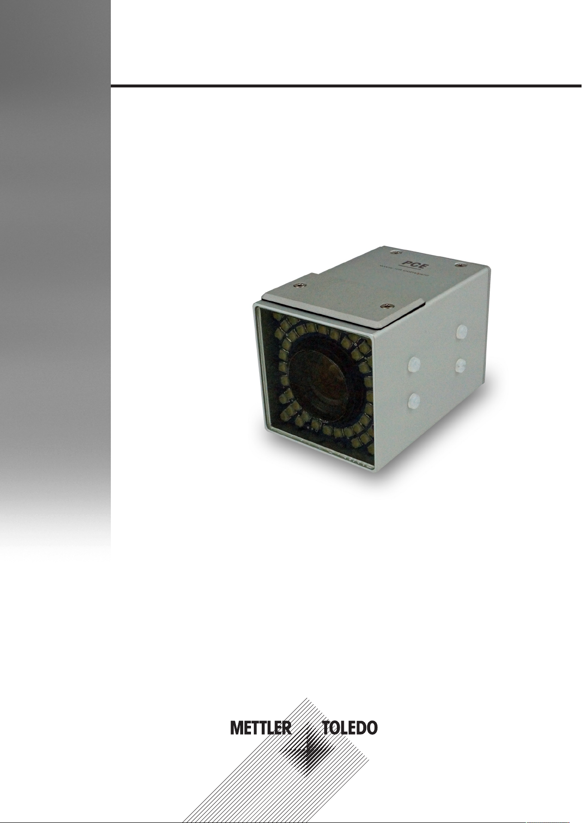
Smart Camera SMC - Series 3
Document Version D
Page 2

Intentionally left blank
2 / 30 Smart Camera SMC - Series 3 - User Manual - Document Version D
Page 3

Table of Contents
1 Introduction 5
1.1 Intended Audience........................................................................................................ 5
1.2 Intended Use and Foreseeable Misuse ............................................................................ 5
1.3 Original Language ....................................................................................................... 5
1.4 Formatting and Meaning............................................................................................... 5
1.5 Contacting METTLER TOLEDO Service............................................................................. 5
1.6 Warranty .................................................................................................................... 6
1.7 Additional Documentation............................................................................................. 6
2 Important Safety Information 7
2.1 Safety Labels and Notice Labels .................................................................................... 7
2.2 General Protective Procedures ....................................................................................... 8
2.3 Safety Information for Various Activities........................................................................... 9
2.4 Special Hazards .......................................................................................................... 10
2.1.1 Hazard Notifications ...................................................................................... 7
2.1.1.1 Definitions of Signal Words ...................................................................... 7
2.1.1.2 Meaning of Hazard Alert Symbols.............................................................. 7
2.1.2 Mandatory Procedures................................................................................... 8
2.1.3 Notice.......................................................................................................... 8
2.1.4 Note ............................................................................................................ 8
2.3.1 Transporting and Moving the Equipment .......................................................... 9
2.3.2 Installing...................................................................................................... 9
2.3.3 Operating the Equipment and Monitoring the Inspection Process......................... 9
2.3.4 Testing and Verifying the Equipment ................................................................ 9
2.3.5 Maintaining, Cleaning and Sanitizing the Equipment ......................................... 9
2.4.1 Electricity ..................................................................................................... 10
2.4.2 Strobe Lights ................................................................................................ 10
2.4.3 Lights and Laser Sensors ............................................................................... 10
3 Equipment Description 11
3.1 Function ..................................................................................................................... 11
3.2 Equipment Overview SMC Series 3................................................................................. 11
3.3 Field of View and Reading Distance ............................................................................... 12
3.4 Center of Camera Image ............................................................................................... 14
4 Installation 15
5 Operation 16
5.1 Operating the SMC ....................................................................................................... 16
5.2 Triggering the SMC Manually......................................................................................... 16
6 Maintenance 17
7 Cleaning 18
7.1 General Cleaning Procedure.......................................................................................... 18
7.2 Cleaning Components Made of Aluminum ...................................................................... 19
7.3 Cleaning the Glass Plate............................................................................................... 19
8 Troubleshooting 20
9 Disposal 21
10 Technical Data 22
10.1 SMC Series 3............................................................................................................... 22
Smart Camera SMC - Series 3 - User Manual - Document Version D 3 / 30
Page 4

Intentionally left blank
4 / 30 Smart Camera SMC - Series 3 - User Manual - Document Version D
Page 5

1 Introduction
1.1 Intended Audience
This User Manual is for all personnel who do the following tasks:
• Setting up a product and changing a product
• Operating the equipment
• Cleaning the equipment
1.2 Intended Use and Foreseeable Misuse
In this manual, the METTLER TOLEDO vision solution, including all of its components, is referred to as the
"equipment".
The equipment must only be used for the visual inspection of products, according to the procedures in this
manual. Any other use of the equipment is considered misuse.
Common foreseeable misuses include the following:
• Replacing or modifying parts without approval from METTLER TOLEDO
• Operating the equipment beyond the limits of the technical specifications
• Not obeying the instructions and safety notes described in this manual
• Disabling the safety devices
• Using the equipment to capture images of persons
1.3 Original Language
The original manual is written in English. If you are reading a translated version of this manual, and you
also need the English original manual, you can ask METTLER TOLEDO to supply it. If you have a question
about the intended meaning of any translated text, consult the original English-language manual.
1.4 Formatting and Meaning
The formats used in this manual have determined meanings. If they are used they denote the following:
Format Meaning
PC
'apostrophes' Names of fields, checkboxes, modes, parameters
<angle brackets> wildcard for tab names of devices (individual names
Bold
Menu Paths, Buttons at the screen surface, fixed tab
names, names of screens and dialogs
can be assigned)
UI texts
1.5 Contacting METTLER TOLEDO Service
Contact your authorized METTLER TOLEDO Service representative about the following products and services:
• Installation
• Integration
• Start-up support
• Commissioning
• Performance verification and audit services to certify that your equipment is maintaining its performance
levels
• Certified, genuine parts
• Emergency repairs and support
• Service contracts customized to your needs
• Customer training
For more information, contact your local and authorized METTLER TOLEDO Service representative using the
link below (and, if necessary, select the applicable country):
http://www.mt.com/contact
Smart Camera SMC - Series 3 - User Manual - Document Version D 5 / 30
Page 6

When you contact the Service Department, have the following information available, if applicable:
• METTLER TOLEDO order number and date
• Equipment name, model, or type
• Serial number
• Production line name
• Software version
• Precise wording of the displayed error message or detailed fault description
• Pictures or videos of the part or problem
1.6 Warranty
For information on warranty, refer to the official METTLER TOLEDO terms and conditions at
http://www.mt.com/us/en/home/site_content/legal/commercial_terms.html.
1.7 Additional Documentation
For details on the individual SMC software refer to the following manuals on www.mt.com/pce-manuals:
• User Manual on SMC OCV software
• User Manual on SMC JData Trans 3.0 software
• User Manual on SMC Color Product Control software
6 / 30 Smart Camera SMC - Series 3 - User Manual - Document Version D
Page 7
2 Important Safety Information
All information related to safety in this manual is important. The information in this chapter is general. There
is other important safety information that you must read throughout the manual.
Important Safety Message
Read and understand all the safety information in the following sections as
well as the safety messages in the rest of this manual.
If you do not follow the safety information and messages, this may lead to property
damage and personal injury up to and including death.
2.1 Safety Labels and Notice Labels
The ISO3864 safety labels are installed at potentially hazardous areas on the equipment. They give special
safety-related notifications. The locations of these labels are given in the drawings supplied with your
equipment. There are three types of safety labels:
• Hazard notifications
• Mandatory procedures
• Prohibitive procedures
Additionally, NOTICE labels may appear on your equipment.
The meanings of the different kinds of labels are explained in the following sections.
Before you transport, install, operate or work on the equipment, find out about the location and meanings of
the labels. Maintain the labels so that they are clear of obstructions and are readable. Do not remove any
labels. Replace any label that is no longer readable.
2.1.1 Hazard Notifications
A hazard notification consists of the following:
• Hazard alert symbol (yellow triangle with black symbol)
• Signal word (DANGER , WARNING , or CAUTION )
• Special notifications related to the hazard (as required)
The signal word labels are attached next to the hazard alert symbol labels on the equipment.
2.1.1.1 Definitions of Signal Words
Signal words describe the level of risk of a particular hazard. The color of the safety label background
indicates the risk, as shown in the following table. The definitions of the signal words are based upon the
ISO3864 definitions.
DANGER (red): This signal word indicates an imminently hazardous situation which,
if not avoided, will result in death or serious injury.
WARNING (orange): This signal word indicates a potentially hazardous situation
which, if not avoided, could result in death or serious injury.
CAUTION (yellow): This signal word indicates a potentially hazardous situation
which, if not avoided, could result in minor or moderate injury.
2.1.1.2 Meaning of Hazard Alert Symbols
The following hazard alert symbols may be installed on your equipment.
Cutting
Impact
Smart Camera SMC - Series 3 - User Manual - Document Version D 7 / 30
Page 8
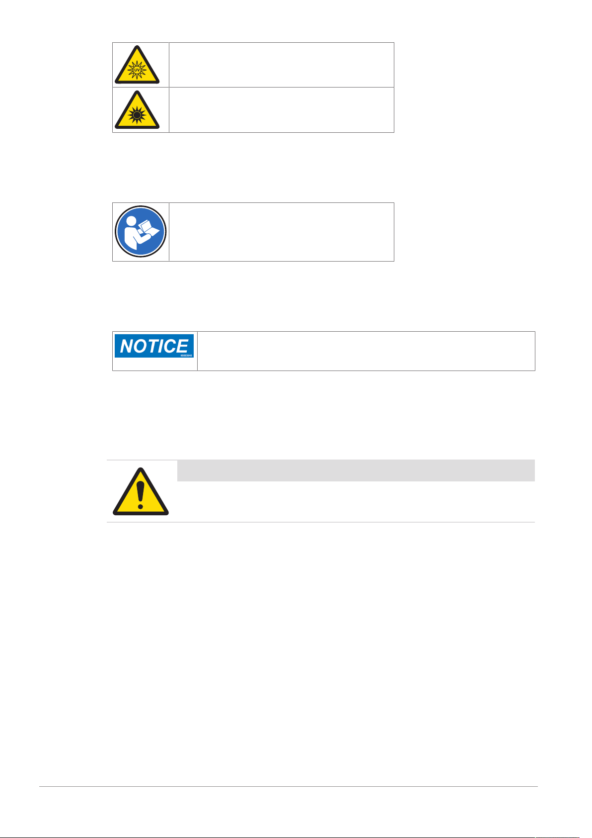
UV light
Optical radiation
2.1.2 Mandatory Procedures
Mandatory procedures alert personnel to special, required actions. The round labels have blue backgrounds
and white symbols. The symbols describe the required action. The following table lists the mandatory
procedures labels which may be installed on your equipment.
Read the manual
2.1.3 Notice
The word NOTICE does not give safety information. It is still an important word to inform you of activities
that may harm the equipment or other property. The following definition is based upon the ANSIZ535
definition.
NOTICE (blue): This indicates important information that is not related to personal
injury which, if ignored, could result in damage to the equipment, damage to
property, malfunctions, erroneous results, or loss of data.
2.1.4 Note
The word NOTE: does not give safety information. It indicates useful supplementary information, hints, and
tips.
2.2 General Protective Procedures
Important Safety Message
Make sure that all personnel who work on or near the equipment are capable
of performing all operations in a safe way.
• Keep the manual in a convenient location near the equipment. Replace the manual if it becomes lost or
damaged.
• Wear Personal Protective Equipment (PPE) in accordance with your plant's safety procedures.
• Understand the hazards of the equipment and the risks related to those hazards before working on or
near the equipment.
• Obey all safety procedures of the local plant.
• Do not wear loose clothing, jewelry, long hair, or anything that can become entangled with the
equipment.
• Be careful around the equipment to avoid hitting your head, arms, or other body parts against the
equipment. Be careful if the equipment is over your head.
• Be careful not to trip over cables or other parts of the equipment.
• Do not move quickly in the area around the equipment.
• Do not climb, hang onto, or use any of the part of the equipment as a support.
• If there is a safety-related malfunction when you are operating the equipment, press the emergency stop
device. Tell the responsible supervisor, and follow the applicable steps approved by your company to fix
the malfunction.
8 / 30 Smart Camera SMC - Series 3 - User Manual - Document Version D
Page 9

2.3 Safety Information for Various Activities
Important Safety Message
Read and understand all parts of the manual before using or working on any
equipment.
The following sections list safety information for particular activities or groups of activities. Refer to the
correct sections in the manual for more detailed instructions.
2.3.1 Transporting and Moving the Equipment
• Only transport or move the equipment if you have the applicable training as defined by your company.
• Your company has sole responsibility for the safe moving and transporting of the equipment.
• Use safe moving procedures during transporting to maintain stability and to prevent the equipment from
tipping or falling.
• Disconnect the electrical supply, the pneumatic supply, and the communication cables before you move
the equipment.
• Use the correct lifting devices. If you use a forklift, lift the equipment at the correct lift points as shown by
the blue lift point labels.
• Blue lift point labels are placed on the equipment to show recommended locations for lifting. These lift
point locations were tested with the manufacturer's forklift trucks. A qualified rigger must make sure that
the lift points are correct for your lifting equipment.
• When you lift the equipment by hand, obey the safe lifting procedures of your company.
2.3.2 Installing
Only install the equipment if you have the applicable training as defined by your company.
2.3.3 Operating the Equipment and Monitoring the Inspection Process
• Before beginning operation, make sure that the area is safe.
• Know the location and effect of each emergency stop button that controls the equipment.
• Do not operate the equipment without protective guards and doors in place.
• Do not reach into path of the products when any conveyors are in motion.
• Do not reach into the area around any sorting device, when the equipment is turned on.
• Make sure the safety circuit is working correctly.
• Do regular inspections of the equipment.
• If there is a fault or change in the equipment behavior, stop the equipment and inform responsible
personnel.
2.3.4 Testing and Verifying the Equipment
Only do testing and verifying of the equipment if you have applicable training as defined by your company.
2.3.5 Maintaining, Cleaning and Sanitizing the Equipment
• Remove all power from the equipment before doing any work.
• Keep the equipment in good working order.
• Follow a preventative maintenance program.
• Replace parts when needed.
• Obey the lockout tagout (LOTO) procedures of the plant.
• Test (validate) the safety circuit after parts are replaced.
• Only use METTLER TOLEDO approved spare parts and accessories.
• Do not make any unauthorized modifications to the equipment.
• Replace safety labels if damaged, missing, or unreadable.
Smart Camera SMC - Series 3 - User Manual - Document Version D 9 / 30
Page 10

• Do a visual check of the equipment at least once during a shift to identify any visual damage or faults.
Report any equipment changes to the responsible supervisor immediately.
• When required for a hygienic production environment, do regular sanitizing of the equipment according
to your company's procedures.
• After cleaning or sanitizing, check all cables, connectors, and pneumatic hoses for leakage, loose
connections, rub marks and damage. Tighten, repair, or replace any faulty cables and air tubing, as
necessary.
2.4 Special Hazards
The following sections describe special instructions for equipment that may have special hazards.
2.4.1 Electricity
• Only work on the electrical systems if you have the applicable electrical training as defined by your
company.
• Keep all electrical enclosure doors closed. If the doors have locks on them, keep them locked.
• Remove all power from the equipment before doing any work.
2.4.2 Strobe Lights
• Strobe lights can cause seizures in individuals with photosensitive epilepsy.
• Individuals with photosensitive epilepsy must not operate the equipment.
• Do not operate the equipment when excessively fatigued or after consuming alcohol.
• Do not look directly at the lights, especially at close distances.
• Avoid placing the equipment in areas with reduced lighting.
• If lights are inside of an enclosure, do not open the enclosure doors when lights are flashing.
2.4.3 Lights and Laser Sensors
• Do not stare directly at any lights or lasers.
• Avoid prolonged exposure to ultraviolet (UV) light, infrared (IR) light, and lasers.
10 / 30 Smart Camera SMC - Series 3 - User Manual - Document Version D
Page 11
3 Equipment Description
3.1 Function
An SMC (Smart Camera) is a camera that sequentially reads pre-printed information from various
packaging surfaces such as labels, bottles, or cartons. The SMC can check both the presence and the
quality of the printed information.
For every product that arrives at the camera, the SMC captures an image. After capturing the image, the
software calculates the characteristics of the product and compares it to reference samples that the user has
taught-in before. In case that one or more of the compared values exceed the set tolerances, the product is
evaluated as 'bad'.
SMCs can process image data on their integrated signal processor. As opposed to PC-based cameras
(such as the HRC) which capture an image and send the result to a connected PC for evaluation, SMCs use
their installed software to evaluate the image by themselves. The user can define an "area of interest" in an
image with so-called control windows and teach the camera how to interpret the information from that
image.
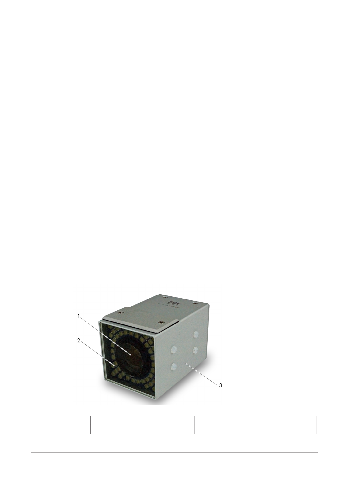
3.2 Equipment Overview SMC Series 3
Components
The hardware of the SMC comprises the following components:
• Housing
• Lens
• Internal illumination
• Mounting block
• Connectors and interfaces
• Status LEDs
• Manual trigger
• Integrated signal processor
• Main board
• Flash memory
• Optical component
In case that the internal illumination is not sufficient, external illumination can be mounted to the SMC by
means of mounting brackets.
SMC Type 330
1
3
Lens
Housing
2
Internal illumination
NOTE: The details of the SMC design may differ dependent on the actual SMC camera type.
Smart Camera SMC - Series 3 - User Manual - Document Version D 11 / 30
Page 12
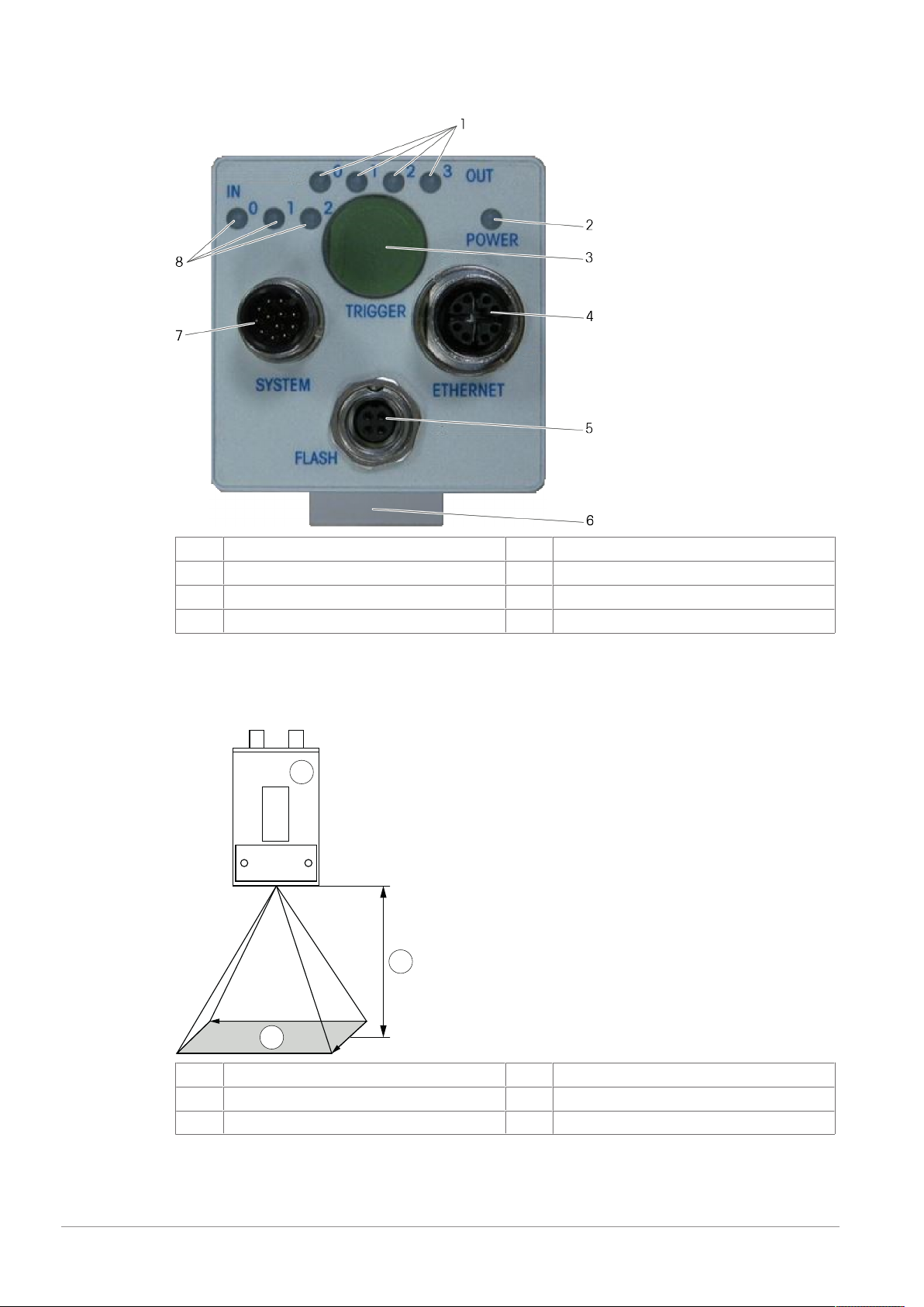
Connections and Interfaces
3
2
1
x
y
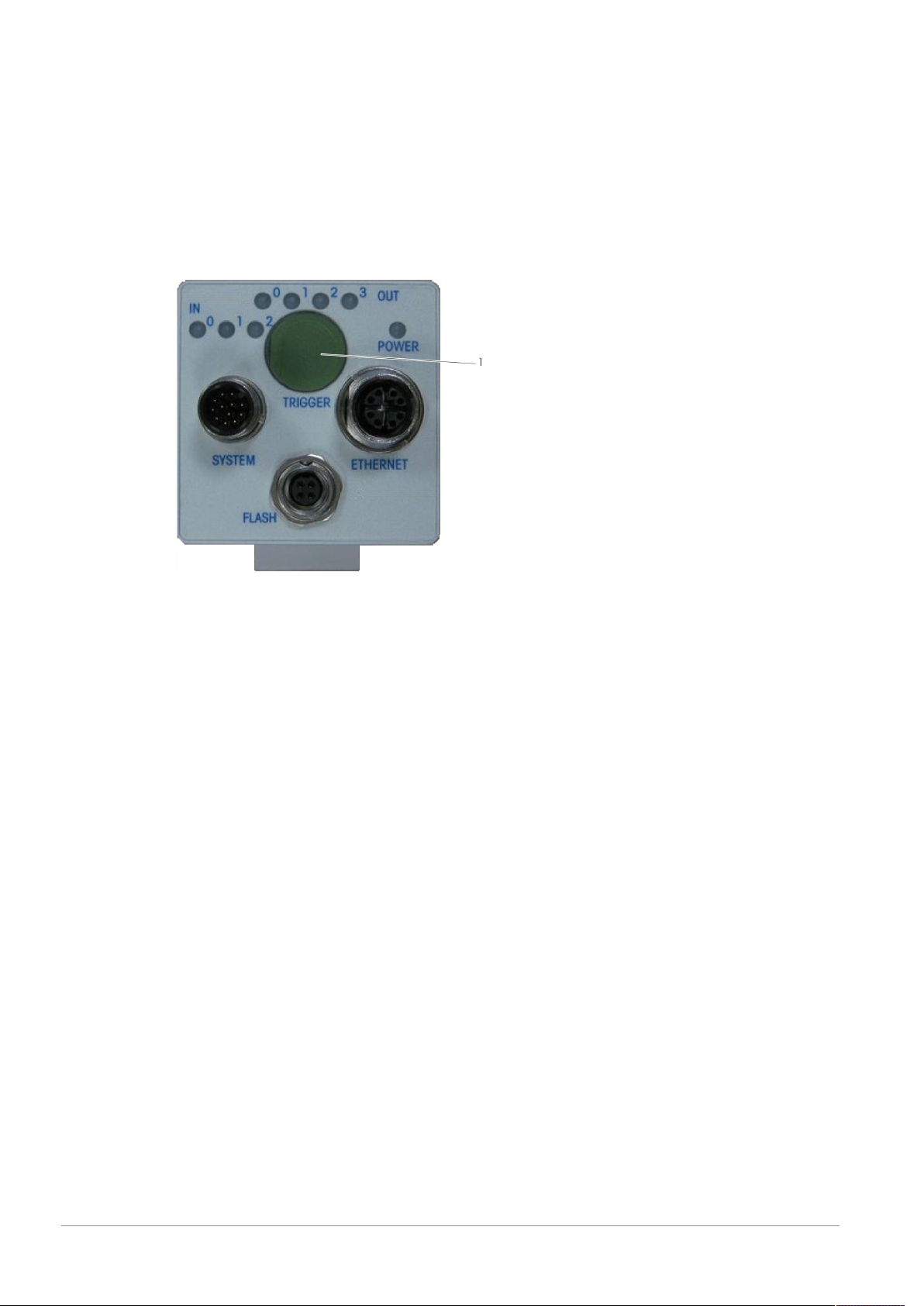
The following picture shows the available connectors and interfaces at the back of the SMC.
1
3
5
7
LED indication for outputs
Button for manual triggering
Connector for external illumination
System connector
2
4
6
8
LED indication for power supply
Ethernet connector
Plastic mounting block
LED indication for inputs
3.3 Field of View and Reading Distance
The image below shows the field of view of the SMC with regard to the SMC housing and the reading
distance.
1
3
SMC
2
Field of view x x axis
Reading distance
y y axis
For the SMC Type320 and Type330, four different lens types are available. The reading distance and the
field of view depend on the lens.
12 / 30 Smart Camera SMC - Series 3 - User Manual - Document Version D
Page 13
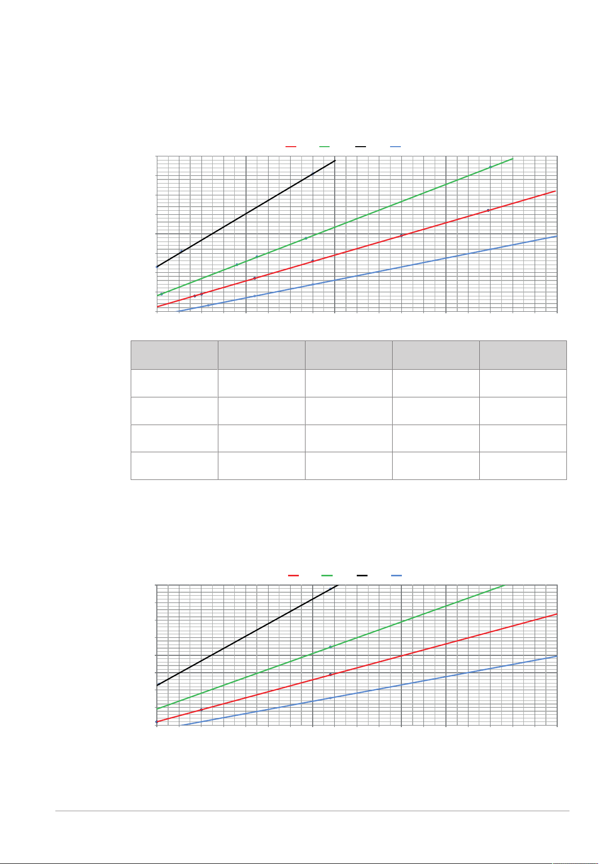
The SMC Type310 features a mini lens that cannot be adjusted. Focal length, field of view, and reading
50
100
150
200
250
300
350
400
450
50 60 70 80 90 100 110 120 13 0 140 150 160 170 180 190 200 210
220 230
12mm 16mm 25mm 8mm
Field of view width (dx) in mm
Reading distance (f) in mm
50
100
150
200
250
300
350
400
450
50 60 70 80 90 100 110 120 130 140 150 160 170 180 19 0 200 210 220 230
12mm 16mm 2 5mm 8mm
Field of view width (dx) in mm
Reading distance (f) in mm
distance are fixed.
Field of View and Reading Distance · SMC Type320
• y axis: Reading distance (f) in mm
• x axis: Field of view width (dx) in mm
Lens Reading distance
range
Reading distance
standard
Field of view range Field of view
8 65 to 210 90 73x55 to
200x150
12 90 to 310 135 67x50 to
200x150
16 191 to 422 191 95x64 to
200x150
25 165 to 405 319 50x38 to
120x90
All dimensions in mm or mm² respectively
Field of View and Reading Distance · SMC Type330
• y axis: Reading distance (f) in mm
• x axis: Field of view width (dx) in mm
standard
95x71
95x71
95x71
95x71
Smart Camera SMC - Series 3 - User Manual - Document Version D 13 / 30
Page 14
Lens Reading distance
1
2
3
27.5 27.5
27.59 27.5
range
Reading distance
standard
Field of view range Field of view
8 38 to 329 128 51x40 to
301x226
12 94 to 488 193 70x51 to
300x225
16 64 to 542 273 35.5x25 to
247x185
25 167 to 536 438 51x38 to
156x117
All dimensions in mm or mm² respectively
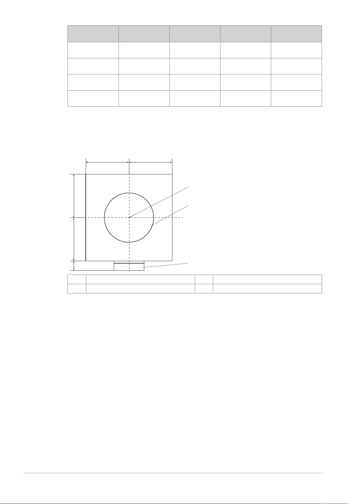
3.4 Center of Camera Image
The image below shows the center of the camera image with regard to the camera housing.
All dimensions are given in mm.
standard
128x96
128x96
128x96
128x96
1
3
Center of camera image
Plastic mounting block
2
Lens
14 / 30 Smart Camera SMC - Series 3 - User Manual - Document Version D
Page 15
4 Installation
DANGER
Electrocution or serious personal injury due to faulty installation
Improperly performing the electrical installation can cause electrocution.
Only qualified personnel may engage the hazardous area (including the electrical
cabinet) and only when appropriate personal protective equipment is used. If the
equipment does not have a power plug, the equipment must only be connected by a
qualified electrician in accordance with national and local electrical codes.
CAUTION
Personal injury or damage to the equipment
The equipment and its software have to be installed by adequately trained personnel only.
For details on the installation refer to the Technical Manual or contact METTLER TOLEDO.
Smart Camera SMC - Series 3 - User Manual - Document Version D 15 / 30
Page 16
5 Operation
5.1 Operating the SMC
The SMC is set-up and operated by means of the respective software. See chapter [Additional Documentation}Page6] for details.
5.2 Triggering the SMC Manually
Manual triggering may be necessary, for example, to capture a test image.
1 To manually trigger the SMC, push the button (1) at the back of the SMC.
ð The SMC captures an image.
2 Check the result in the software. If the image quality is poor, contact your Supervisor to adjust the optical
settings.
16 / 30 Smart Camera SMC - Series 3 - User Manual - Document Version D
Page 17

6 Maintenance
CAUTION
Personal injury or damage to the equipment
The equipment and its components have to be maintained by adequately trained
personnel only. For details on the maintenance refer to the Technical Manual or contact
METTLER TOLEDO.
Smart Camera SMC - Series 3 - User Manual - Document Version D 17 / 30
Page 18
7 Cleaning
7.1 General Cleaning Procedure
Regular cleaning is very important to keep good system operation. When cleaning your equipment follow
these steps in consultation with your Supervisor (if applicable):
1 Ensure that the production is stopped.
2 Switch off the equipment. If applicable, isolate the equipment from the electrical power supply. Follow
LOTO.
3 Let the equipment cool down.
4 Cover electrical equipment and other surrounding equipment that may get damaged by the cleaning
process.
5 Clean the equipment following the instructions in the Cleaning chapters.
6 After cleaning, ensure that all labels are available and readable. Replace any worn or missing labels.
7 Return the equipment to its normal operation condition. Follow LOTO. Before you restart the equipment,
make sure that all safety devices are back in their original positions and correctly fastened. For example,
if you removed any guards for cleaning, make sure that you reinstall them.
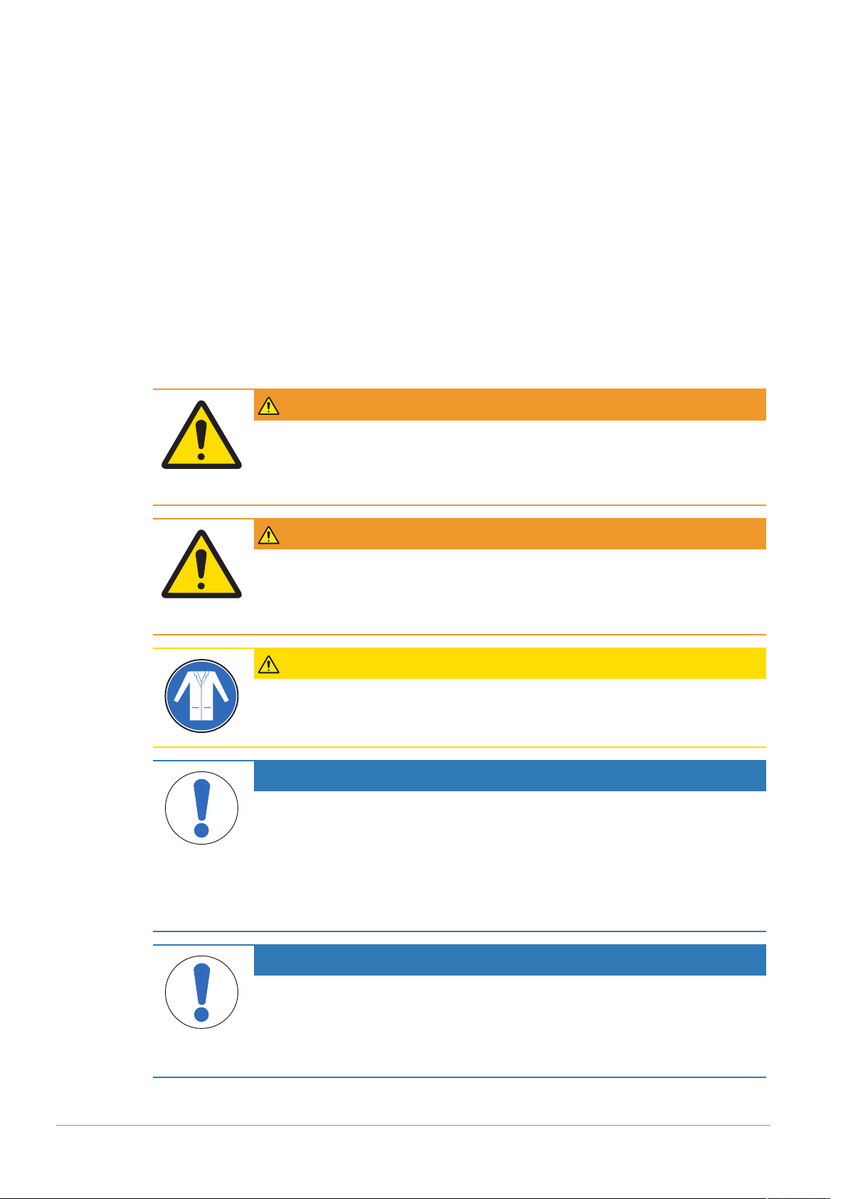
WARNING
Personal injury due to non-compliance to company-specific LOTO
LOTO (Lockout-Tagout) procedures may differ from company to company. Before starting
to work at the equipment inform yourself about the LOTO procedure at the company or
plant.
WARNING
Personal injury and damage to the equipment due to hot parts
During operation, some parts of the equipment may get hot. To avoid personal injury and
damage to the equipment, let the equipment cool down to room temperature before
handling the equipment (e.g. cleaning or maintenance).
CAUTION
Personal damage due to detergents
Wear sufficient protective clothing and hand protection as recommended by the
manufacturer of any detergents used.
NOTICE
Damage due to careless cleaning
The equipment components are made of different materials that have to cleaned using
different detergents. Only use the detergents given in the respective chapter. Do not use
pure alcohol, concentrated acid, or lye.
To prevent water from entering the equipment make sure that all doors and enclosures are
securely closed.
Do not use a high-pressure jet to hose down the equipment.
NOTICE
Damage to products due to unsuitable cleaning and sanitizing procedures
Depending on the products processed in your application (for example, anti-cancer drugs
or food), cleaning and sanitizing may be subject to special regulations. Ensure to be
informed about any relevant regulations and procedures concerning your specific application.
18 / 30 Smart Camera SMC - Series 3 - User Manual - Document Version D
Page 19

7.2 Cleaning Components Made of Aluminum
In general, components made of aluminum are anodized to protect them against corrosion. During
anodization, an invisible, resistant layer of aluminum oxide is created that protects the equipment.
Depending on the operational use and the conditions in the working environment, the equipment can
become dirty to some extent. The most common causes are fine iron particles in the air, active gases, the
accumulation of sediments, and the build-up of salts.
Overview
Interval 1x per day
Required tools and
working materials
1 Observe the steps explained in the chapter [General Cleaning Procedure}Page18].
2 Clean the aluminum components using a slightly wet cloth without applying too much pressure. Change
the cloth several times. This prevents the surface from being scratched by dust particles in the cloth.
3 Wash off any residues with a suitable amount of warm water.
4 Dry the equipment using a cloth without applying too much pressure.
• Warm water
• Several soft, lint-free cloths
7.3 Cleaning the Glass Plate
The plate at the front of the camera is made of glass.
Overview
Interval 1x per week
Required tools and
working materials
• Mild glass cleaner or mild solution of soap and water
• Soft, lint-free cloth
1 Observe the steps explained in the chapter [General Cleaning Procedure}Page18].
2 Clean the glass plate at the camera front using a cloth and a suitable detergent.
3 Dry the glass plate using a cloth.
Smart Camera SMC - Series 3 - User Manual - Document Version D 19 / 30
Page 20
8 Troubleshooting
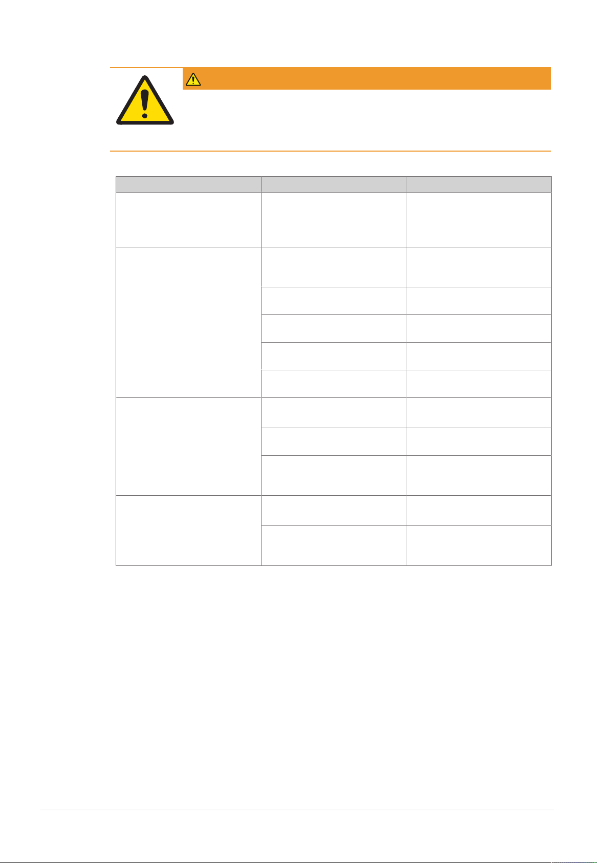
WARNING
Personal injury due to inadequate qualification
Before attempting any corrective action, be sure that the person doing the action has been
trained on the equipment and has read the entire manual. Failure to do so can result in
injury and/or property damage.
Errors and Malfunctions at the SMC
Error/Malfunction Probable Cause Solution
Equipment does not start. No power supply or power supply
not sufficient.
Faulty electrical connection of
equipment.
Image quality is poor. Faulty optical settings. Capture a test image. Contact your
Unsuitable mounting position of
the SMC.
External illumination is not
sufficient.
Faulty alignment of external illumination.
Faulty electrical connection of
external illumination.
Bad products are not detected. Glass plate is covered or dirty. Remove any obstructions.
Faulty electrical connection of
equipment.
Faulty optical settings. Capture a test image. Contact your
Good products are evaluated as
bad.
Glass plate is covered or dirty. Remove any obstructions.
Faulty optical settings. Capture a test image. Contact your
Contact your Supervisor.
Supervisor to adjust the optical
settings.
Contact your Supervisor.
Contact your Supervisor.
Contact your Supervisor.
Contact your Supervisor.
Clean the glass plate.
Contact your Supervisor.
Supervisor to adjust the optical
settings.
Clean the glass plate.
Supervisor to adjust the optical
settings.
20 / 30 Smart Camera SMC - Series 3 - User Manual - Document Version D
Page 21

9 Disposal
In conformance with the European Directive 2012/19/EU on Waste Electrical and
Electronic Equipment (WEEE) this device may not be disposed of in domestic waste. This
also applies to countries outside the EU, per their specific requirements.
Please dispose of this product in accordance with local regulations at the collecting point
specified for electrical and electronic equipment. If you have any questions, please contact
the responsible authority or the distributor from which you purchased this device. Should
this device be passed on to other parties, the content of this regulation must also be
related.
Smart Camera SMC - Series 3 - User Manual - Document Version D 21 / 30
Page 22

10 Technical Data
10.1 SMC Series 3
Specifications
Technical Data of SMC Series 3
Housing Aluminum (anodized)
Protection of housing IP65
Power supply 24VDC, min. 20V, max. 28V,
Image processing Internally, with special machine vision processor
Inputs 3 inputs 24VDC, max. 28V permanent
Outputs 4 Outputs 24VDC, type PNP
Interface Ethernet 100/1000Mbit/s, LAN
Interface RS-232
Illumination White LEDs in flash operation
Standard lens C-Mount, 12mm focal length
Camera inclination angle 0-10 degrees in relation to vertical and product horizontal
Environmental conditions
at transport and storage
Environmental conditions
at operation
Weight approx. 430g
Current during start up: max. about 1A,
Current during operation: about 150mA
Response threshold:
High: about >13V
Low: about <7V
Max. 100mA permanent, max. 400mA peak
Short-circuit-proof, protected against overload and protected against external
voltage
Other available lenses: 8mm, 16mm, 25mm
-20°C (-4°F) to +80°C (+176°F),
Max. humidity 90%, non-condensing
0°C (+32°F) to +50°C (+122°F),
Max. humidity 80%, non-condensing
Specification SMC Type 310 SMC Type 320 SMC Type 330
Resolution
(widthxheight) in pixels
Standard reading
distance f and corresponding field of view
FoV
Acquisition time 9ms 24ms 12ms
Acquisition time plus
processing time
Housing • Straight
736x480 1600x1200 2048x1536
f=95mm
FoV=47mmx 30mm
40ms 65ms 60ms
• Size 25
• 55mmx 55mmx
72mm
f=90mm
FoV=95mmx 71mm
• Straight
– Size 21
– 55mmx
55mmx 91mm
• 90°
– Size 23
– 80mmx
60mmx
100mm
f=128mm
FoV=128mmx 96mm
• Straight
• Size 24
• 55mmx 55mmx
100mm
22 / 30 Smart Camera SMC - Series 3 - User Manual - Document Version D
Page 23
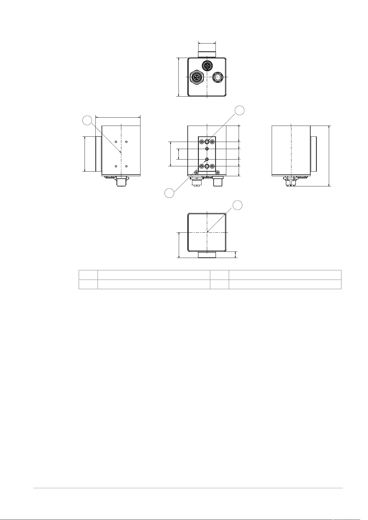
Dimensional Drawing SMC Type 310
25
55
50
64
87
0
23
33
48
58
72
15
35
36.5
9
1
2
3
4
Housing size 25
1
3
Optional mounting position
2x M4x0.7
2
4
2x M6x1
Center of camera picture
Smart Camera SMC - Series 3 - User Manual - Document Version D 23 / 30
Page 24
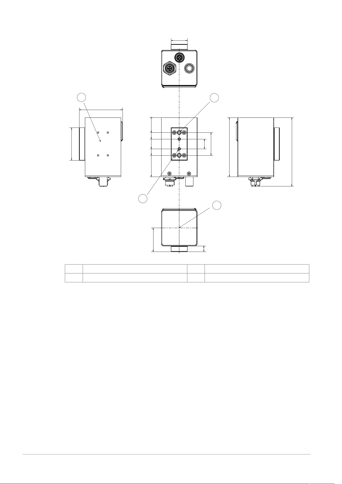
Dimensional Drawing SMC Type 320
25
0
23
67
33
48
58
91
9
15
50
35
91
36.5
105.5
1
2
3
4
Housing size 21
1
3
Optional mounting position
2x M4x0.7
2
4
2x M6x1
Center of camera picture
24 / 30 Smart Camera SMC - Series 3 - User Manual - Document Version D
Page 25
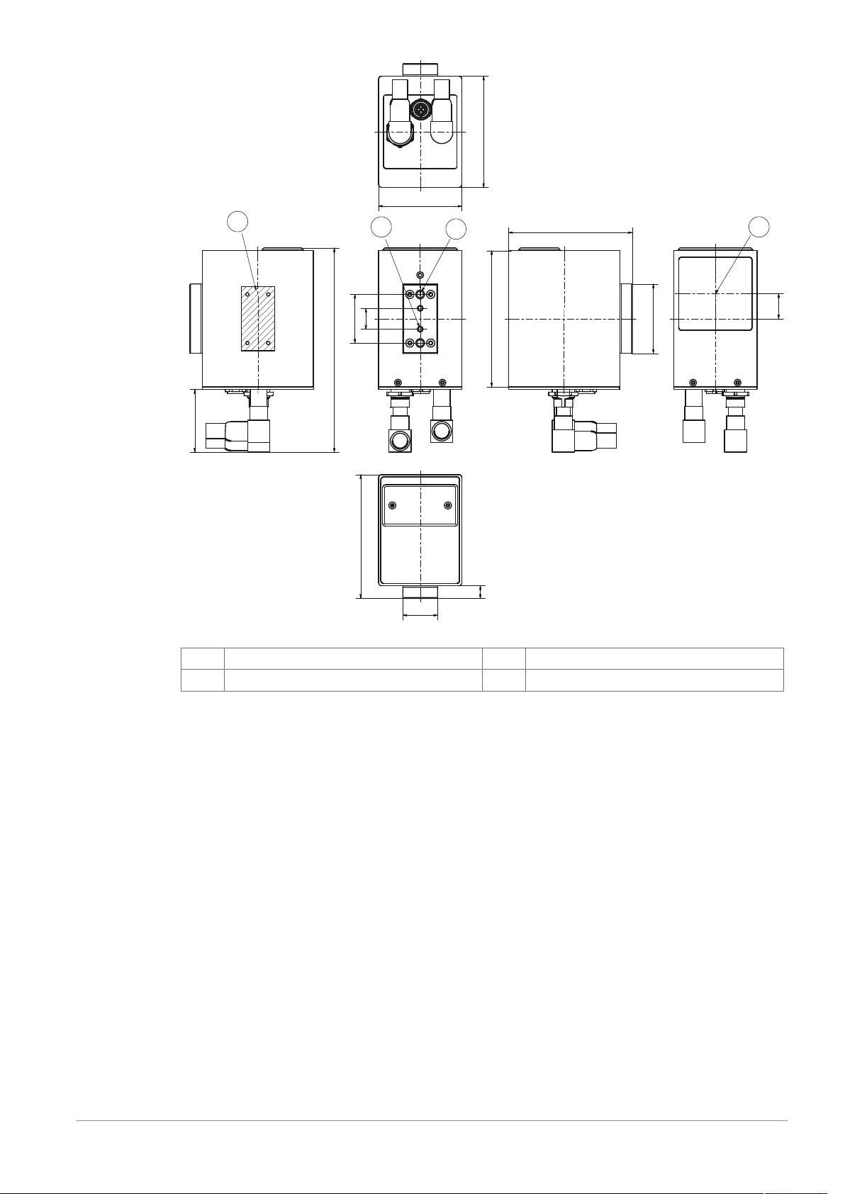
80
50
98
35
15
147
45
89
9
18
60
89
25
1
2
3
4
Housing size 23
1
3
Optional mounting position
2x M6x1
2
4
2x M4x0.7
Center of camera picture
Smart Camera SMC - Series 3 - User Manual - Document Version D 25 / 30
Page 26
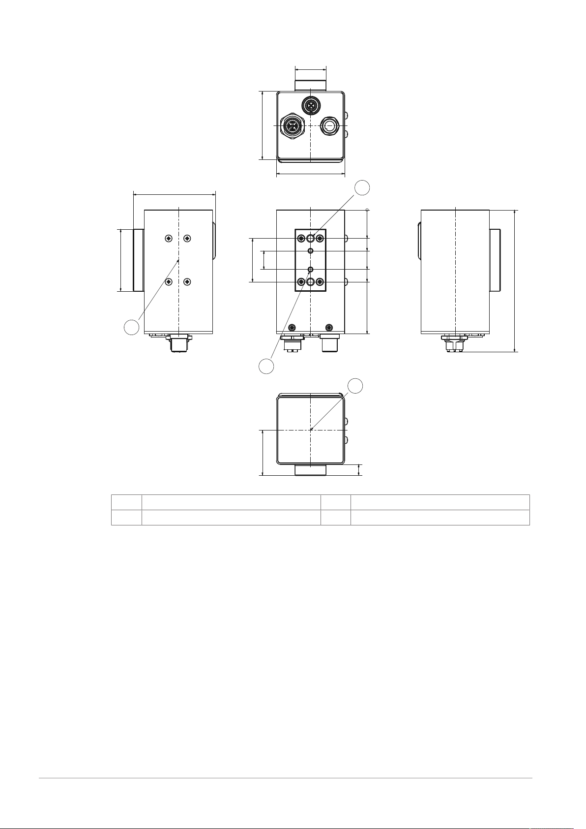
Dimensional Drawing SMC Type 330
25
55
0
23
33
48
58
100
67
55
15
35
36.5
115
50
9
1
2
3
4
Housing size 24
1
3
Optional mounting position
2x M4x0.7
2
4
2x M6x1
Center of camera picture
26 / 30 Smart Camera SMC - Series 3 - User Manual - Document Version D
Page 27
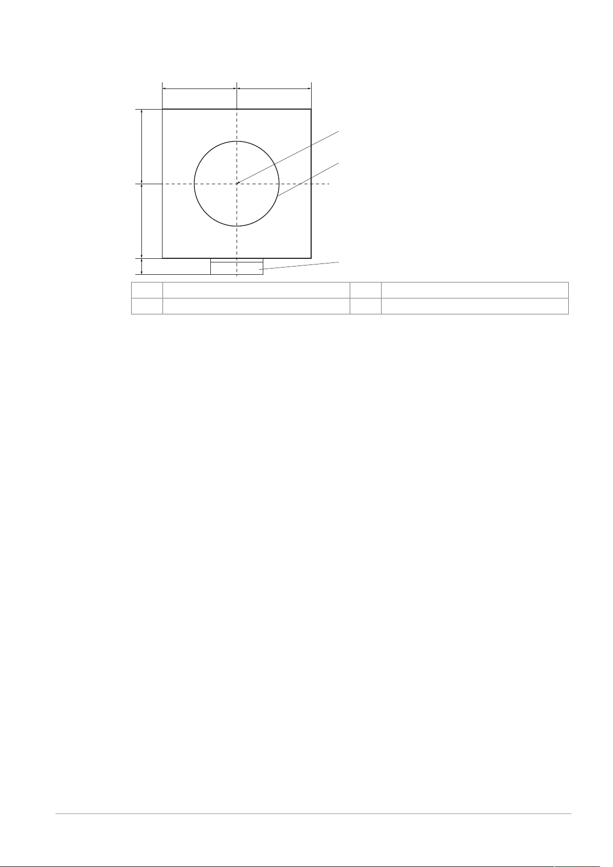
Center of Image with regard to Housing Dimensions
1
2
3
27.5 27.5
27.59 27.5
The following drawing shows the center of image in relation to the housing dimensions.
1
3
Center of image
Plastic mounting block
2
Lens
Smart Camera SMC - Series 3 - User Manual - Document Version D 27 / 30
Page 28

Intentionally left blank
28 / 30 Smart Camera SMC - Series 3 - User Manual - Document Version D
Page 29

Intentionally left blank
Smart Camera SMC - Series 3 - User Manual - Document Version D 29 / 30
Page 30
Pharmacontrol Electronic GmbH
Harzstraße 1
64646 Heppenheim, Germany
Tel. +49 6252 6736 0
Fax +49 6252 6736 111
www.mt.com
Subject to technical changes.
© Pharmacontrol Electronic GmbH 03/2019
Smart Camera SMC - Series 3 - User Manual - Document Version D
www.mt.com/pce
For more information
 Loading...