

Page 1
Operation Manual
Multi-parameter Transmitter M800
Transmitter Multi-parameter M800
52 121 825 D
Page 2

© 05/2019 Mettler-Toledo GmbH, Process Analytics
Subject to technical changes.
Printed in Switzerland. 52 121 825 D
Page 3

Transmitter M800 3
Operation Manual
Multi-parameter
Transmitter M800
© 05/2019 Mettler-Toledo GmbH, CH-8606 Greifensee, Switzerland Transmitter M800
Printed in Switzerland 52 121 825 D
Page 4

Transmitter M800 4
© 05/2019 Mettler-Toledo GmbH, CH-8606 Greifensee, Switzerland Transmitter M800
Printed in Switzerland 52 121 825 D
Page 5

Transmitter M800 5
Content
1 Introduction __________________________________________________________________________________________ 11
2 Safety instructions _____________________________________________________________________________________ 13
2.1 Denitionofequipment
and documentation symbols and designations ________________________________________________________________ 13
2.2 Correct disposal of the unit ________________________________________________________________________ 14
3 Unit overview _________________________________________________________________________________________ 15
3.1 Overview _______________________________________________________________________________________ 15
3.1.1 1-Channel Version ________________________________________________________________________ 15
3.1.2 2-Channel and 4-Channel Version ____________________________________________________________ 16
3.2 Display ________________________________________________________________________________________ 17
3.2.1 Start Screen _____________________________________________________________________________ 17
3.2.2 Activation Menu Screen ____________________________________________________________________ 17
3.3 Graphic Trend Measurement ________________________________________________________________________ 18
3.3.1 Activation Trend Display Screen ______________________________________________________________ 18
3.3.2 Settings for Trend Display Screen _____________________________________________________________ 19
3.3.3 Deactivation Trend Display Screen ____________________________________________________________ 19
3.4 Control / Navigation _______________________________________________________________________________ 20
3.4.1 Menu Structure ___________________________________________________________________________ 20
3.4.2 Operating Elements _______________________________________________________________________ 21
3.4.3 Entry of Data ____________________________________________________________________________ 21
3.4.4 Selection Menus __________________________________________________________________________ 21
3.4.5 ”Save changes” Dialog ____________________________________________________________________ 21
3.4.6 Security Passwords _______________________________________________________________________ 22
3.4.7 Display ________________________________________________________________________________ 22
4 Installation instruction __________________________________________________________________________________ 23
4.1 Unpackingandinspectionofequipment _______________________________________________________________ 23
4.2 Mounting 1/2 DIN Versions (PC housing) _____________________________________________________________ 24
4.2.1 Dimensions 1/2 DIN Version (PC housing) _____________________________________________________ 24
4.2.2 Mounting Procedure – 1/2 DIN Version (PC housing) _____________________________________________ 25
4.2.3 1/2 DIN Version (PC housing) – Panel Mounting ________________________________________________ 26
4.2.4 1/2 DIN Version – Wall Mounting ____________________________________________________________ 26
4.2.5 1/2 DIN Version (PC housing) – Pipe Mounting _________________________________________________ 27
4.3 Mounting Stainless Steel Version _____________________________________________________________________ 28
4.3.1 Dimensions Stainless Steel Version ___________________________________________________________ 28
4.3.2 Mounting Procedure – Stainless Steel Version ___________________________________________________ 29
4.3.3 Stainless Steel Version – Wall Mounting _______________________________________________________ 30
4.3.4 Stainless Steel Version – Pipe Mounting _______________________________________________________ 30
4.4 Electrical Connection ______________________________________________________________________________ 31
4.5 TerminalDenition _______________________________________________________________________________ 32
4.5.1 M800 1-Channel _________________________________________________________________________ 32
4.5.1.1 InPro8000 Series Turbidity Sensor __________________________________________________ 33
4.5.2 M800 2-Channel _________________________________________________________________________ 34
4.5.3 M800 4-Channel _________________________________________________________________________ 35
4.5.4 M800 1-Channel: TB2 – Conductivity 2e/4e Analog Sensors _______________________________________ 36
4.5.5 M800 1-Channel: TB2 – pH/ORP Analog Sensors _______________________________________________ 36
4.5.6 M800 1-Channel: TB2 – Oxygen Analog Sensors ________________________________________________ 37
4.5.7 M800 2- and 4-Channel: TB2 and TB4 – Terminal Assignment for Optical Oxygen, CO
d4e and 5000TOCi ISM Sensors ____________________________________________________________________ 38
4.5.8 M800 2- and 4-Channel: TB2 and TB4 – Terminal Assignment for pH, Amp. Oxygen, Cond 4e, CO
Sensors 39
4.5.9 M800 1-Channel: TB3 – Terminal Assignment for Optical Oxygen, CO
hi, UniCond2e and UniCond4e ISM Sen-
2
sors 40
4.5.10 M800 1-Channel: TB3 – Terminal Assignment for pH and Turbidity ISM Sensors ________________________ 41
4.5.11 M800 2- and 4-Channel Water:
TB3 – Terminal Assignment for Flow Sensors ___________________________________________________________ 41
4.6 Connection of Flow Sensor _________________________________________________________________________ 42
4.6.1 Flow Sensor Input Wiring Kit ________________________________________________________________ 42
4.6.2 Kit Contents _____________________________________________________________________________ 42
4.6.3 Flow sensor wiring for Compatible Sensors _____________________________________________________ 42
4.6.4 Wiringfor”HIGH”typeowsensors __________________________________________________________ 43
4.6.5 Wiringfor”LOW”typeowsensors ___________________________________________________________ 45
4.6.6 Wiringfor”TYPE2”owsensors _____________________________________________________________ 45
hi, UniCond2e, UniCon-
2
and O3 ISM
2
© 05/2019 Mettler-Toledo GmbH, CH-8606 Greifensee, Switzerland Transmitter M800
Printed in Switzerland 52 121 825 D
Page 6

Transmitter M800 6
5 Placing transmitter in, or out, of service ___________________________________________________________________ 46
5.1 Placing transmitter in service _______________________________________________________________________ 46
5.2 Placing transmitter out of service ____________________________________________________________________ 46
6 Guided Setup _________________________________________________________________________________________ 47
7 Calibration ___________________________________________________________________________________________ 48
7.1 Sensor Calibration ________________________________________________________________________________ 48
7.2 Calibration of UniCond2e and UniCond4e Sensors (ISM Sensors only) _______________________________________ 48
7.2.1 Conductivity Calibration of UniCond2e and UniCond4e Sensors _____________________________________ 48
7.2.1.1 One-Point Calibration ____________________________________________________________ 50
7.2.1.2 Two-Point Calibration ____________________________________________________________ 51
7.2.1.3 Process Calibration _____________________________________________________________ 52
7.2.2 Temperature Calibration of UniCond2e Sensors and UniCond4e Sensors ______________________________ 53
7.2.2.1 One-Point Calibration ____________________________________________________________ 53
7.2.2.2 Two-Point Calibration ____________________________________________________________ 54
7.3 Calibration of Cond2e Sensors or Cond4e Sensors ______________________________________________________ 56
7.3.1 One-Point Calibration _____________________________________________________________________ 56
7.3.2 Two-Point Calibration _____________________________________________________________________ 57
7.3.3 Process Calibration _______________________________________________________________________ 57
7.4 pH Calibration ___________________________________________________________________________________ 58
7.4.1 One-Point Calibration _____________________________________________________________________ 58
7.4.2 Two-Point Calibration _____________________________________________________________________ 59
7.4.3 Process Calibration _______________________________________________________________________ 60
7.5 ORP Calibration of pH Sensors ______________________________________________________________________ 60
7.6 Calibration of Amperometric Oxygen Sensors ___________________________________________________________ 61
7.6.1 One-Point Calibration _____________________________________________________________________ 61
7.6.2 Process Calibration _______________________________________________________________________ 62
7.7 Calibration of Optical Oxygen Sensors (ISM Sensors only) _________________________________________________ 63
7.7.1 One-Point Calibration _____________________________________________________________________ 63
7.7.2 Two-Point Calibration _____________________________________________________________________ 64
7.7.3 Process Calibration _______________________________________________________________________ 64
7.8 Calibration of Dissolved Carbon Dioxide Sensors (ISM Sensors only) ________________________________________ 65
7.8.1 One-Point Calibration _____________________________________________________________________ 65
7.8.2 Two-Point Calibration _____________________________________________________________________ 66
7.8.3 Process Calibration _______________________________________________________________________ 66
7.9 Calibration of Thermal Conductivity CO
(C02 high) Sensors (ISM Sensors only) _______________________________ 67
2
7.9.1 One-Point Calibration ______________________________________________________________________ 67
7.9.2 Process Calibration _______________________________________________________________________ 68
7.10 Calibration of O
Sensors (ISM Sensors only) ___________________________________________________________ 68
3
7.10.1 One-Point Calibration ______________________________________________________________________ 69
7.10.2 Process Calibration _______________________________________________________________________ 70
7.11 Calibration of Flow Sensors (ISM Sensors only) _________________________________________________________ 71
7.11.1 One-Point Calibration _____________________________________________________________________ 71
7.11.2 Two-Point Calibration _____________________________________________________________________ 72
7.12 Turbidity Calibration (InPro8000 Series) ______________________________________________________________ 73
7.12.1 Multi-Point Calibration _____________________________________________________________________ 74
7.12.2 Process Calibration _______________________________________________________________________ 75
7.12.3 In-Situ Calibration ________________________________________________________________________ 76
7.12.4 Manual Calibration (Edit) __________________________________________________________________ 78
7.13 Turbidity Calibration (InPro8600i) ___________________________________________________________________ 78
7.13.1 Process Calibration _______________________________________________________________________ 79
7.14 SensorVerication ________________________________________________________________________________ 80
7.15 Edit Calibration Constants for Flow Sensors ____________________________________________________________ 80
7.16 UniCond2e Electronics Calibration ___________________________________________________________________ 81
7.17 Meter Calibration _________________________________________________________________________________ 81
7.17.1 Resistance (Analog Sensors only) ____________________________________________________________ 81
7.17.2 Temperature (Analog Sensors only) ___________________________________________________________ 83
7.17.3 Voltage _________________________________________________________________________________ 83
7.17.4 Current _________________________________________________________________________________ 84
7.17.5 Rg ____________________________________________________________________________________ 84
7.17.6 Rr _____________________________________________________________________________________ 84
7.17.7 Flow meter calibration _____________________________________________________________________ 85
7.18 FlowMeterVerication ____________________________________________________________________________ 86
7.19 Analog Output Calibration __________________________________________________________________________ 86
7.20 Analog Input Calibration ___________________________________________________________________________ 87
7.21 Maintenance ____________________________________________________________________________________ 87
© 05/2019 Mettler-Toledo GmbH, CH-8606 Greifensee, Switzerland Transmitter M800
Printed in Switzerland 52 121 825 D
Page 7

Transmitter M800 7
8 Conguration _________________________________________________________________________________________ 88
8.1 Measurement ___________________________________________________________________________________ 88
8.1.1 Channel Setup ___________________________________________________________________________ 88
8.1.2 Derived Measurements ____________________________________________________________________ 90
8.1.2.1 % Rejection measurement ________________________________________________________ 90
8.1.2.2 Calculated pH (Power Plant Applications only) ________________________________________ 90
8.1.2.3 Calculated CO
(Power plant applications only) ________________________________________ 91
2
8.1.3 Display Mode ____________________________________________________________________________ 91
8.1.4 Parameter related Settings __________________________________________________________________ 92
8.1.4.1 Conductivity Settings _____________________________________________________________ 92
8.1.4.2 pH Settings ____________________________________________________________________ 93
8.1.4.3 Settings for Oxygen Measurement Based on Amperometric Sensors _________________________ 94
8.1.4.4 Settings for Oxygen Measurement Based on Optical Sensors ______________________________ 95
8.1.4.5 Dissolved Carbon Dioxide Settings __________________________________________________ 96
8.1.4.6 Settings for Thermal Conductivity Dissolved CO
Measurement (CO2 hi) _____________________ 97
2
8.1.4.7 Settings for TOC Measurement _____________________________________________________ 97
8.1.4.8 Settings for Flow Measurement _____________________________________________________ 98
8.1.4.9 Settings for Turbidity Sensors (InPro8000 Series) ______________________________________ 98
8.1.4.10 Settings for Turbidity Sensors (InPro8600i) ___________________________________________ 98
8.1.4.11 Deionization Capacity (DI-Cap™) __________________________________________________ 99
8.1.5 Concentration Curve Table _________________________________________________________________100
8.2 Temperature Source (Analog Sensors only) ___________________________________________________________100
8.3 Analog Outputs _________________________________________________________________________________ 101
8.4 Set Points _____________________________________________________________________________________ 102
8.5 ISM Setup (ISM Sensors only) _____________________________________________________________________ 103
8.5.1 Sensor Monitor __________________________________________________________________________ 103
8.5.2 CIP Cycle Limit __________________________________________________________________________ 105
8.5.3 SIP Cycle Limit __________________________________________________________________________ 106
8.5.4 AutoClave Cycle Limit ____________________________________________________________________ 107
8.5.5 DLI Stress Adjustment ____________________________________________________________________ 107
8.5.6 SAN Cycle Parameters ____________________________________________________________________ 108
8.5.7 Reset Counters for UniCond2e Sensors _______________________________________________________ 108
8.5.8 Set Calibration Interval for UniCond2e Sensors _________________________________________________ 109
8.6 General Alarm __________________________________________________________________________________ 109
8.7 ISM / Sensor Alarm ______________________________________________________________________________ 109
8.8 Clean ________________________________________________________________________________________ 110
8.9 Display Setup __________________________________________________________________________________ 110
8.10 Digital Inputs ___________________________________________________________________________________ 111
8.11 System _______________________________________________________________________________________ 111
8.12 PID Controller __________________________________________________________________________________ 112
8.13 Service _______________________________________________________________________________________ 116
8.13.1 Set Analog Outputs ______________________________________________________________________ 116
8.13.2 Read Analog Outputs
_____________________________________________________________ 116
8.13.3 Read Analog Inputs ______________________________________________________________________ 116
8.13.4 Set Relay ______________________________________________________________________________ 116
8.13.5 Read Relay ____________________________________________________________________________ 116
8.13.6 Read Digital Inputs ______________________________________________________________________ 116
8.13.7 Memory _______________________________________________________________________________ 117
8.13.8 Display _______________________________________________________________________________ 117
8.13.9 Calibrate TouchPad ______________________________________________________________________117
8.13.10 Channel Diagnostic ______________________________________________________________________117
8.14 Technical Service _______________________________________________________________________________117
8.15 User Management _______________________________________________________________________________ 118
8.16 Reset _________________________________________________________________________________________ 118
8.16.1 System Reset ___________________________________________________________________________ 118
8.16.2 Reset Sensor Calibration for Optical DO Sensors ________________________________________________ 119
8.16.3 Reset Sensor Calibration for UniCond2e Sensors ________________________________________________ 119
8.16.4 Reset Total Flow _________________________________________________________________________ 119
8.16.5 Reset for CO
hi Measurement ______________________________________________________________ 120
2
8.16.6 Reset for Turbidity Sensor __________________________________________________________________120
8.17 RS485 Output __________________________________________________________________________________ 120
8.17.1 PrinterOutputConguration ________________________________________________________________ 121
8.17.2 DataLogConguration ___________________________________________________________________ 121
8.18 USB Measurement Interface _______________________________________________________________________ 122
© 05/2019 Mettler-Toledo GmbH, CH-8606 Greifensee, Switzerland Transmitter M800
Printed in Switzerland 52 121 825 D
Page 8

Transmitter M800 8
9 ISM ________________________________________________________________________________________________ 123
9.1 iMonitor _______________________________________________________________________________________ 123
9.2 Messages _____________________________________________________________________________________ 124
9.3 ISM Diagnostics ________________________________________________________________________________ 124
9.3.1 pH/ORP, Oxygen, O
and Cond4e Sensors ____________________________________________________ 125
3
9.3.2 UniCond2e and UniCond4e Sensors _________________________________________________________ 125
9.4 Calibration Data ________________________________________________________________________________ 126
9.4.1 Calibration Data for All ISM Sensors excluding UniCond2e and UniCond4e ___________________________ 126
9.4.2 Calibration Data for UniCond2e and UniCond4e Sensors _________________________________________ 127
9.5 Sensor Info ____________________________________________________________________________________ 127
9.6 HW / SW Version _______________________________________________________________________________128
9.7 Log Book _____________________________________________________________________________________ 128
10 Wizards _____________________________________________________________________________________________ 129
10.1 Set Wizard ____________________________________________________________________________________ 129
10.2 Access to Wizards ______________________________________________________________________________ 129
11 Maintenance _________________________________________________________________________________________ 130
11.1 Front panel cleaning _____________________________________________________________________________ 130
12 Software History ______________________________________________________________________________________ 130
12.1 M800 Process _________________________________________________________________________________ 130
12.2 M800 Water ___________________________________________________________________________________130
13 Troubleshooting ______________________________________________________________________________________131
13.1 Cond (resistive) Error messages /
Warning- and Alarm list for analog sensors _________________________________________________________________131
13.2 Cond (resistive) Error messages /
Warning- and Alarm list for ISM sensors ____________________________________________________________________ 132
13.3 pH Error messages / Warning- and Alarm list __________________________________________________________132
13.3.1 pH sensors except dual membrane pH electrodes _______________________________________________ 132
13.3.2 Dual membrane pH electrodes (pH / pNa) ____________________________________________________ 133
13.3.3 ORP messages _________________________________________________________________________ 133
13.4 Amperometric O
Error messages /
2
Warning- and Alarm list ________________________________________________________________________________134
13.4.1 High level oxygen sensors _________________________________________________________________ 134
13.4.2 Low level oxygen sensors _________________________________________________________________ 134
13.4.3 Trace oxygen sensors ____________________________________________________________________135
13.5 Warning- and Alarm Indication _____________________________________________________________________ 135
13.5.1 Warning Indication_______________________________________________________________________135
13.5.2 Alarm Indication _________________________________________________________________________ 136
14 Ordering Information __________________________________________________________________________________ 137
14.1 Transmitter Overview _____________________________________________________________________________ 137
14.2 Accessories and Spare Parts _______________________________________________________________________ 137
15 Specications ________________________________________________________________________________________ 138
15.1 Generalspecications ____________________________________________________________________________ 138
15.2 Electricalspecications ___________________________________________________________________________ 142
15.3 Mechanicalspecications _________________________________________________________________________ 143
15.3.1 Polycarbonate (PC) Versions _______________________________________________________________ 143
15.3.2 Stainless Steel Versions ___________________________________________________________________143
15.4 Environmentalspecications ______________________________________________________________________ 143
15.5 ExClassication ________________________________________________________________________________ 144
15.5.1 M800 4-Channel and 2-Channel versions ____________________________________________________ 144
15.5.2 Type plate M800 1-Channel versions ________________________________________________________145
16 Warranty ____________________________________________________________________________________________ 146
© 05/2019 Mettler-Toledo GmbH, CH-8606 Greifensee, Switzerland Transmitter M800
Printed in Switzerland 52 121 825 D
Page 9

Transmitter M800 9
17 Buffer tables _________________________________________________________________________________________ 147
17.1 Standard pH buffers _____________________________________________________________________________ 147
17.1.1 Mettler-9 _______________________________________________________________________________147
17.1.2 Mettler-10 _____________________________________________________________________________148
17.1.3 NIST Technical Buffers ____________________________________________________________________148
17.1.4 NIST standard buffers (DIN and JIS 19266: 2000–01) __________________________________________ 149
17.1.5 Hach buffers ___________________________________________________________________________ 149
17.1.6 Ciba (94) buffers ________________________________________________________________________ 150
17.1.7 Merck Titrisole, Riedel-de-Haën Fixanale _____________________________________________________150
17.1.8 WTW buffers ___________________________________________________________________________ 151
17.1.9 JIS Z 8802 buffers _______________________________________________________________________ 151
17.2 Dual membrane pH electrode buffers ________________________________________________________________ 152
17.2.1 Mettler-pH / pNa buffers (Na+ 3.9M) _________________________________________________________ 152
© 05/2019 Mettler-Toledo GmbH, CH-8606 Greifensee, Switzerland Transmitter M800
Printed in Switzerland 52 121 825 D
Page 10

Transmitter M800 10
© 05/2019 Mettler-Toledo GmbH, CH-8606 Greifensee, Switzerland Transmitter M800
Printed in Switzerland 52 121 825 D
Page 11

Transmitter M800 11
1 Introduction
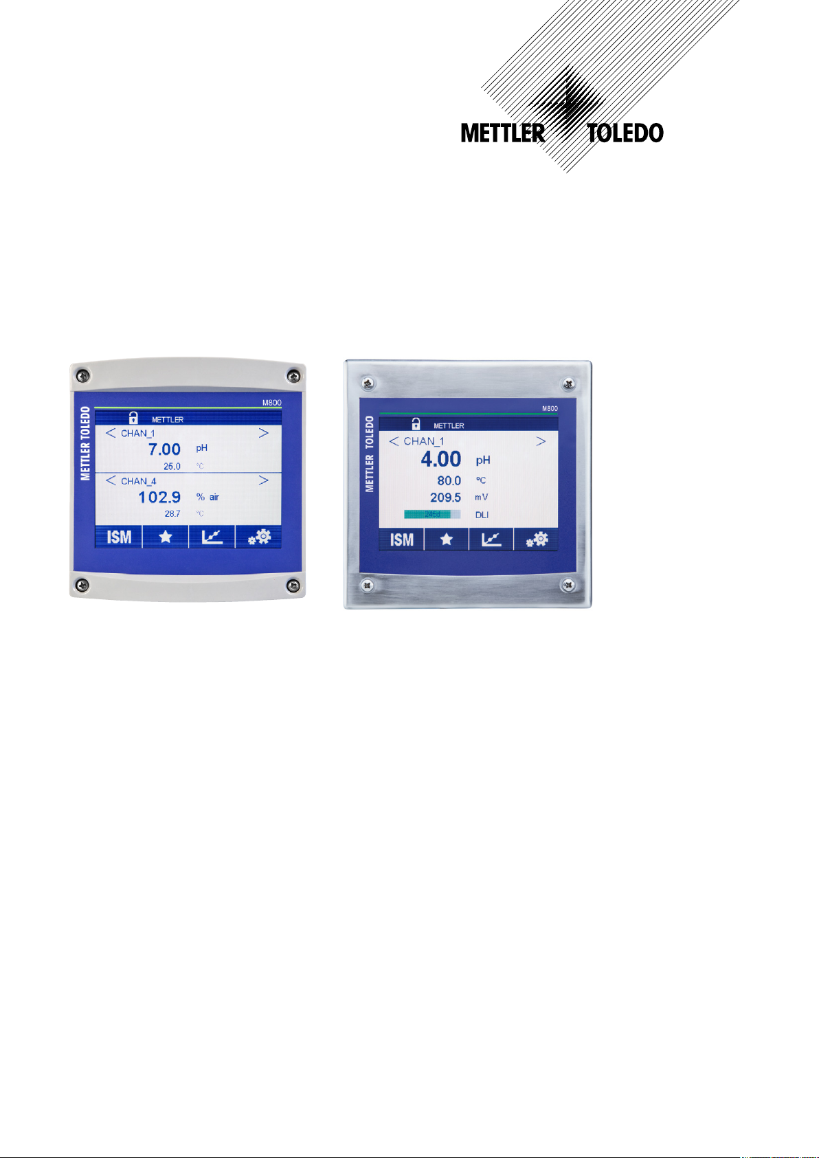
Statement of Intended Use – The M800 Multi-parameter transmitter is an online process instrument for measuring various properties of fluids and gases. These include conductivity, dissolved
oxygen, O2 gas, dissolved ozone, dissolved carbon dioxide, pH / ORP, flow and turbidity. The
M800 is available in different versions. The version indicates the amount of measurement parameters which can be covered and the kind of parameter. The version are indicated through
there part numbers on the label of the transmitter.
The M800 version with hygienic, polished stainless steel housing allows application in the field
of biotechnology, food processing and in the pharmaceutical industry.
M800 parameter fit guide for 2-channel and 4-channel version
These versions are compatible with the following (digital) ISM and flow sensors.
1)
Parameter
Water Process
2-channel 4-channel 2-channel 4-channel
pH/ORP • • • •
pH/pNa – – • •
UniCond 2-e • • • •
Conductivity 4-e • • • •
Amp. Dissolved Oxygen
– / • / –
3)
– / • / –
3)
• / • / •
2)
• / • / •
ppm / ppb / trace
Amp. Oxygen gas
– / • / – 3) – / • / –
3)
• / • / •
2)
• / • / •
ppm / ppb / trace
Optical Dissolved Oxygen •
Dissolved Carbon Dioxide
3)
– – • •
3)
•
2), 4)
•
•
(InPro5000i)
hi (InPro5500i) – – •
CO
2
4)
•
TOC • • – –
Dissolved Ozone • • – –
Flow • • – –
1) Process models are provided with PC housing or stainless steel housing
2) INGOLD sensors
3) THORNTON sensors
4) 2-channel: An opt. dissolved sensor or a CO
Optical dissolved sensors and CO
hi sensors have to be connected to channel 2 and / or to channel 4.
2
hi sensor has to be connected to channel 2. 4-channel:
2
2)
2)
2), 4)
4)
© 05/2019 Mettler-Toledo GmbH, CH-8606 Greifensee, Switzerland Transmitter M800
Printed in Switzerland 52 121 825 D
Page 12

Transmitter M800 12
M800 parameter fit guide for 1-channel version
These version is compatible with the following (digital) ISM and analog sensors.
1)
Parameter
Process 1-channel
Analog ISM
pH/ORP • •
pH/pNa – •
UniCond 2-e / UniCond 4-e – / – • / •
Conductivity 2-e /
• / • – / •
Conductivity 4-e
Amp. Dissolved Oxygen
• / • / •
2)
• / • / •
2)
ppm / ppb / trace
Amp. Oxygen gas
• / • / •
2)
• / • / •
2)
ppm / ppb / trace
Optical Dissolved Oxygen – •
Dissolved Carbon Dioxide
– •
2)
(InPro5000i)
hi (InPro5500i) – •
CO
2
Turbidity • (backscatter) •
1) Process models are provided with PC housing or stainless steel housing
2) INGOLD sensors
A colored touch screen conveys measuring data and setup information. The menu structure allows the operator to modify all operational parameters by using the touch screen. A menu-lockout feature, with password protection, is available to prevent the unauthorized use of the meter.
The M800 Multi-parameter transmitter can be configured to use up to eight analog and / or up to
eight relay outputs for process control.
TheM800Multi-parametertransmitterisequippedwithaUSBcommunicationinterface.Thisinterface provides up- and download capabilities of the transmitter configuration via a Personal
Computer (PC).
This description corresponds to the firmware release, version 1.2. Changes are taking place
constantly, without prior notification.
© 05/2019 Mettler-Toledo GmbH, CH-8606 Greifensee, Switzerland Transmitter M800
Printed in Switzerland 52 121 825 D
Page 13

Transmitter M800 13
2 Safety instructions
This manual includes safety information with the following designations and formats.
2.1 Denitionofequipment
and documentation symbols and designations
WARNING: POTENTIAL FOR PERSONAL INJURY.
a
CAUTION: Possible instrument damage or malfunction.
a
NOTE: Important operating information.
h
On the transmitter or in this manual text indicates: Caution and / or other possible hazard includ-
ing risk of electric shock (refer to accompanying documents).
a
The following is a list of general safety instructions and warnings. Failure to adhere to these in-
structionscanresultindamagetotheequipmentand/orpersonalinjurytotheoperator.
a
– The M800 Transmitter should be installed and operated only by personnel familiar with
thetransmitterandwhoarequalifiedforsuchwork.
– The M800 Transmitter must only be operated under the specified operating conditions
(see chapter 15 “Specifications”).
– Repair of the M800 Transmitter must be performed by authorized, trained personnel only.
– With the exception of routine maintenance, cleaning procedures, as described in this manu-
al, the M800 Transmitter must not be tampered with or altered in
any manner.
– Mettler-Toledo accepts no responsibility for damage caused by unauthorized modifications
to the transmitter.
– Follow all warnings, cautions, and instructions indicated on and supplied with this product.
– Installequipmentasspecifiedinthisinstructionmanual.Followappropriatelocalandna-
tional codes.
– Protective covers must be in place at all times during normal operation.
– Ifthisequipmentisusedinamannernotspecifiedbythemanufacturer,theprotectionpro-
vided by it against hazards may be void.
WARNINGS:
– Installationofcableconnectionsandservicingofthisproductrequireaccesstoshockhazard
voltage levels.
– Main power and relay contacts wired to a separate power source must be disconnected be-
fore servicing.
– Switchorcircuitbreakershallbeincloseproximitytotheequipmentandwithineasyreach
oftheOPERATOR;itshallbemarkedasthedisconnectingdevicefortheequipment.
– Main power must employ a switch or circuit breaker as the disconnecting device for the
equipment.
– Electrical installation must be in accordance with the National Electrical Code and / or any
other applicable national or local codes.
© 05/2019 Mettler-Toledo GmbH, CH-8606 Greifensee, Switzerland Transmitter M800
Printed in Switzerland 52 121 825 D
Page 14

Transmitter M800 14
NOTE: RELAY CONTROL ACTION
h
NOTE: PROCESS UPSETS
h
NOTE: This is a 4-wire-product with an active 4–20 mA analog output.
h
theM800Transmitterrelayswillalwaysde-energizeonlossofpower,equivalenttonormal state, regardless of relay state setting for powered operation. Configure any control
system using these relays with fail-safe logic accordingly.
Because process and safety conditions may depend on consistent operation of this transmitter, provide appropriate means to maintain operation during sensor cleaning, replacement, or sensor or instrument calibration.
Please do not supply power to terminal 3 to 10 of TB1 and terminal 1 to 8 of TB3.
2.2 Correct disposal of the unit
When the transmitter is finally removed from service, observe all local environmental regulations
for proper disposal.
© 05/2019 Mettler-Toledo GmbH, CH-8606 Greifensee, Switzerland Transmitter M800
Printed in Switzerland 52 121 825 D
Page 15
Transmitter M800 15
3 Unit overview
The M800 models are available as follows:
– in 1/2 DIN case size in polycarbonate
– in stainless steel.
The M800 1/2 DIN polycarbonate versions are suitable for panel-, wall- or pipe mount. The
M800 stainless steel versions are suitable for wall- or pipe mount.
3.1 Overview
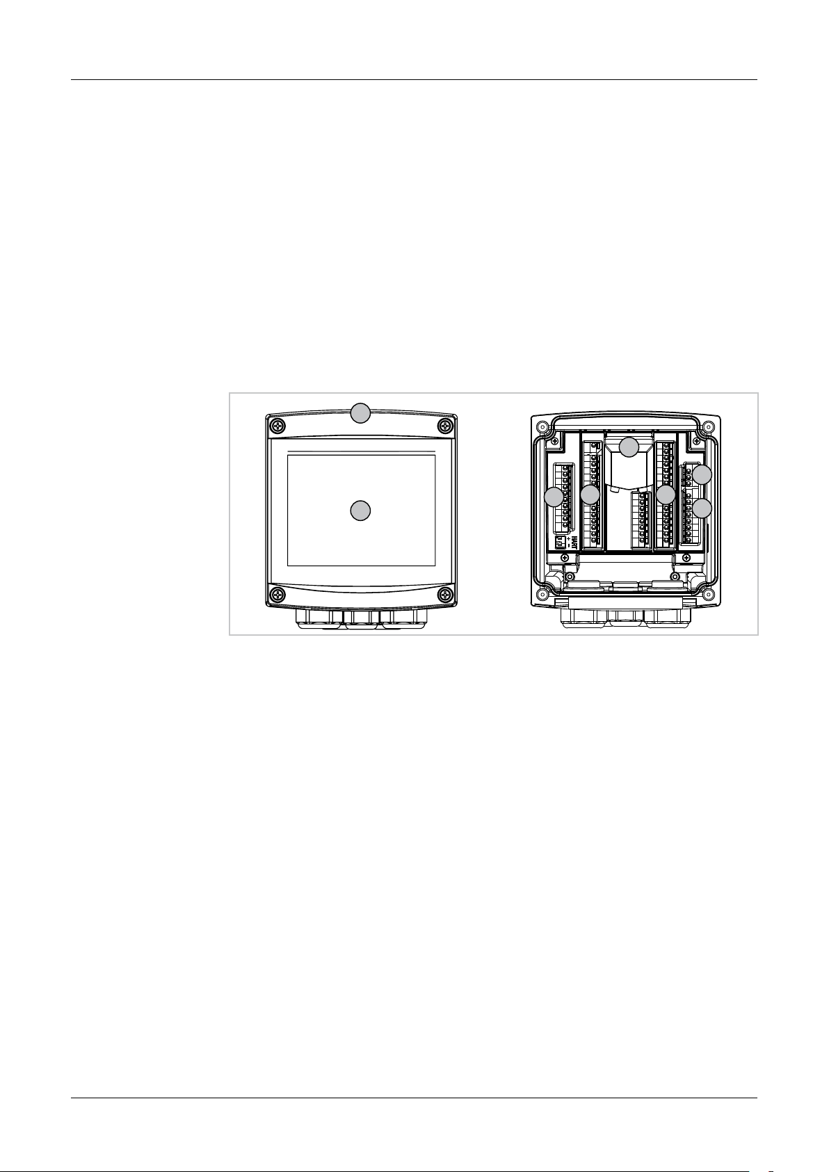
3.1.1 1-Channel Version
1
METTLER TOLEDO
M800
TB1
6 6
5
TB2
2
7
RECEIVER
TB3
TB4
EMITTER
TB5
3
4
Fig. 1: Overview 1-channel version
1 Housing, polycarbonate or stainless steel
2 VGA screen
3 Power supply terminals
4 Relay output terminals
5 Analog output / Digital input terminals
6 Sensor input terminals
7 Connection Turbidity sensor (InPro8000 Series)
© 05/2019 Mettler-Toledo GmbH, CH-8606 Greifensee, Switzerland Transmitter M800
Printed in Switzerland 52 121 825 D
Page 16
Transmitter M800 16
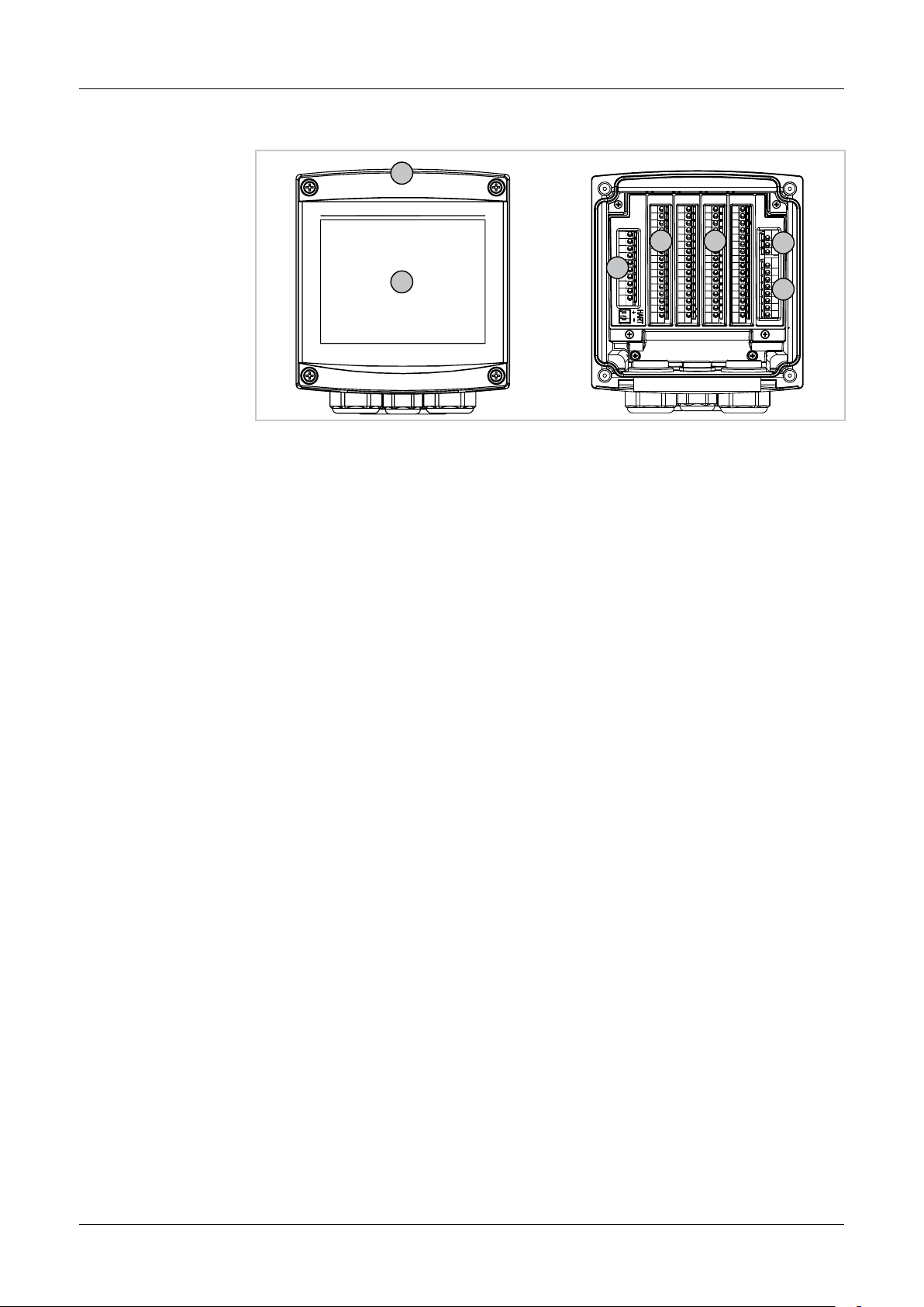
3.1.2 2-Channel and 4-Channel Version
1
TB2
M800
METTLER TOLEDO
2
Fig. 2: Overview 1-channel version
1 Housing, polycarbonate or stainless steel
2 VGA screen
3 Power supply terminals
4 Relay output terminals
5 Analog output / Digital input terminals
6 Sensor input terminals
TB1
5
TB3 TB4 TB5
6 6
TB6
3
4
© 05/2019 Mettler-Toledo GmbH, CH-8606 Greifensee, Switzerland Transmitter M800
Printed in Switzerland 52 121 825 D
Page 17
Transmitter M800 17
3.2 Display
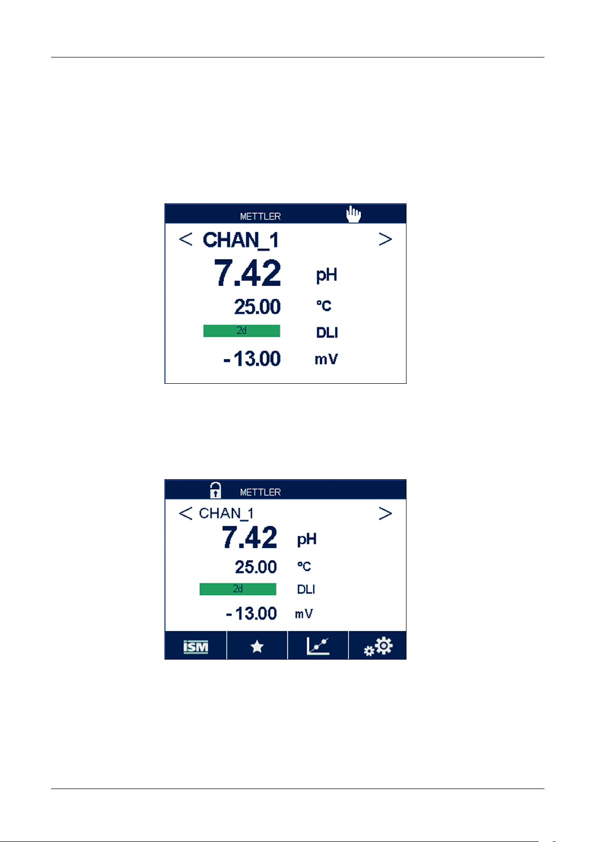
3.2.1 Start Screen
After starting the M800, the following Start Screen (logout screen) is shown automatically. To re-
turn form the Menu Screen to the Start Screen press s. The M800 will return automatically after
240 seconds from the Menu Screen or any configuration screen to the Start Screen if the user
has not pressed the touch screen.
3.2.2 Activation Menu Screen
While the M800 shows the Start Screen (logout screen) touch the display to activate the Menu
Screen. To return to the Menu Screen from other menus press H.
© 05/2019 Mettler-Toledo GmbH, CH-8606 Greifensee, Switzerland Transmitter M800
Printed in Switzerland 52 121 825 D
Page 18
Transmitter M800 18
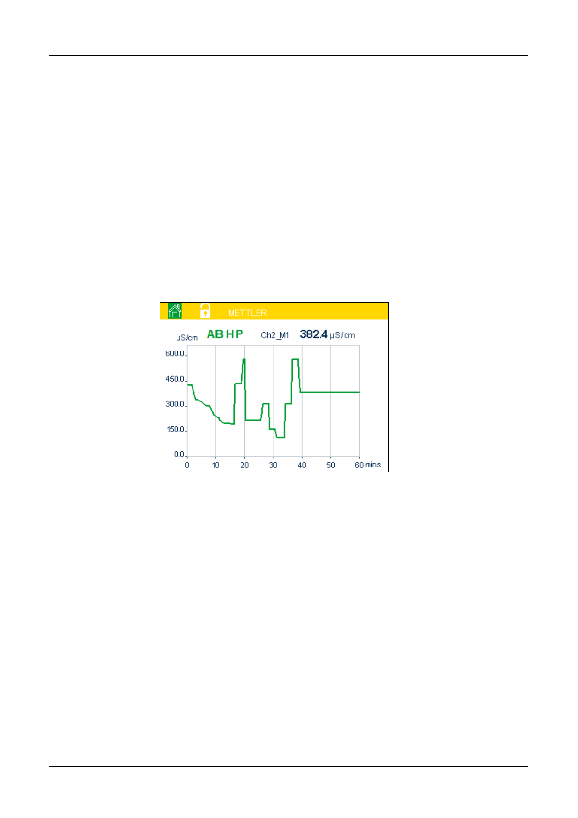
3.3 Graphic Trend Measurement
Any single measurement may be displayed as a trend measurement over time. Measurement
values will be indicated by a value on the Y-axis and time elapsed on the X-axis of the graph
displayed. An actual measurement for the selected value will also be displayed numerically
above the graphic trend display. The measurement value is refreshed once per second.
Graphic trending will only display the data within maximum/minimum range. Out of range values or invalid values will not be displayed. The Y-axis will display the maximum value unit with
its range; X-axis unit uses “mins” for minutes for measurements less than one hour and “hrs” for
one day. 4 scales for X/Y-axis. The maximum value on Y-axis is one decimal place.
3.3.1 Activation Trend Display Screen
While the M800 displays the Menu Screen, touch any measurement value line of the display
screen twice (1-chan, 2-chan, 4-meas, 8-meas) to activate the trend display for that measurement.
If a sensor is disconnected/connected a pop-up window come up; after closing the window, it
will go back to the Menu Screen.
Red/yellow bar on top line will display for any message occurring during trending. ‘H’, ‘P’,”AB”
will display when this channel is in hold or process.
© 05/2019 Mettler-Toledo GmbH, CH-8606 Greifensee, Switzerland Transmitter M800
Printed in Switzerland 52 121 825 D
Page 19

Transmitter M800 19
3.3.2 Settings for Trend Display Screen
For setting configurations, touch any area of the graphic trend display to go to the pop-up window of this measurement parameter. Settings are at the default values. However, these settings
may be changed when options are available, as needed.
Time: Option button. For graphic display time (X-axis)
1-h (default value)
1-day
NOTE: 1 h means: 1 meas storage/15 seconds, totally 240 measurements for 1h. 1 day
h
means: 1 meas storage/6 minutes, totally 240 measurements for 1 day;
Range: Option button
Default(default value)
Individual
When “Default” modes are set for the maximum or minimum value, this indicates the full measurement range for this unit. A Max or Min button is not displayed. If setting is selectable, the
user can set maximum and minimum settings manually.
Max: Edit button.
Maximum value of this unit on Y-axis. xxxxxx, floating decimal point.
Min: Edit button.
Minimum value of this unit on Y-axis. xxxxxx, floating decimal point.
Max Value > Min Value
NOTE: Settings for Y-and Y-axis and the corresponding measurement values are stored the trans-
h
mitters memory. A power down returns to default settings.
3.3.3 Deactivation Trend Display Screen
Press H in activated graphic trend screen to return to Menu Screen.
NOTE: If a sensor is disconnected/connected a pop-up window come up; after closing the win-
h
dow, it will go back to the Menu Screen.
© 05/2019 Mettler-Toledo GmbH, CH-8606 Greifensee, Switzerland Transmitter M800
Printed in Switzerland 52 121 825 D
Page 20
Transmitter M800 20
3.4 Control / Navigation
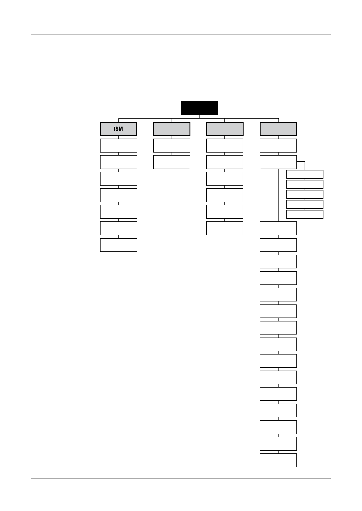
3.4.1 Menu Structure
Below is the structure of the M800 menu tree:
Menu Screen
M800
iMonitor
Messages
ISM Diagnostics
Calibration Data
Sensor Info
HW/SW Version
Log Book
S
Wizard
Favorite 1…4
Set Wizard
c
Calibration
Calibrate Sensor
Calibrate
Electronics
Calibrate Meter
Calibrate
Analog Outputs
Calibrate
Analog Inputs
Maintenance
C
Configuration
Guided Setup
Measurement
Temperature Source
Analog Outputs
Set Points
ISM Setup
General Alarm
ISM/Sensor Alarm
Channel Setup
Display Mode
Parameter Setting
Concentration
Curve Table
Clean
Display Setup
Digital Inputs
System
PID Controller
Service
Tech Service
User Management
Reset
RS485 Output
© 05/2019 Mettler-Toledo GmbH, CH-8606 Greifensee, Switzerland Transmitter M800
Printed in Switzerland 52 121 825 D
Page 21

Transmitter M800 21
3.4.2 Operating Elements
Operating element Description
F
s
S
c
C
H
c
p
< >
e
Enter Menu screen
Enter Start screen
Enter ISM menu
Enter Favorite menu
Enter Calibration menu
EnterCongurationmenu
Return to Menu screen (see chapter 3.2.2 “Activation Menu Screen”)
Enter next-lower menu level, here e.g. iMonitor, Messages or ISM Diagnostics
Return to next-higher menu level
Change between pages within one menu level
2-channel and 4-channel: Change between the channels
Conrmvaluesandselectedoptions.PressESCandthechangesarenot
stored.
3.4.3 Entry of Data
The M800 displays a keypad for modifying values. Press the e button and the transmitter will
store the value. Press the ESC button to exit the keypad without changing data.
NOTE: For some values, the units can be modified. In this case the keypad shows a button with
h
NOTE: For some entries letters and/or numbers can be used. In this case the keypad shows a
h
a U. To select another unit for the entered value on the keypad press the U button. To return
again press the 0–9 button.
button ‘A,a,0’. Press this button to change between capital letters, small letters and numbers on
the keypad.
3.4.4 Selection Menus
Somemenusrequireaselectionofaparameter/data.Inthiscasethetransmitterdisplaysa
pop up window. Press the according field to select the value. The pop-up window will be closed
and the selection will be stored.
3.4.5 ”Save changes” Dialog
If the M800 brings up the ”Save changes” dialog there are the following options. No will discard
the entered values, Yes will save changes made and Cancel will bring you back to continue
configuring.
© 05/2019 Mettler-Toledo GmbH, CH-8606 Greifensee, Switzerland Transmitter M800
Printed in Switzerland 52 121 825 D
Page 22

Transmitter M800 22
3.4.6 Security Passwords
The M800 Transmitter allows a security lock-out of various menus. If the security lock-out
feature of the transmitter has been enabled, a security password must be entered to allow access to the menu. See chapter 8.15 “User Management”.
3.4.7 Display
NOTE: In the event of an alarm or other error conditions the M800 Transmitter will display a
h
NOTE: During calibrations, clean, Digital In with Analog Output / Relay / USB in HOLD state, a
h
flashing bar graph on the display. This bar graph will remain until the condition that caused it
has been cleared (see chapter 13.5 “Warning- and Alarm Indication”).
flashing ”H” (HOLD) will appear in the upper right corner of the display for the corresponding
channel. This symbol will remain for 20 sec., after end of calibration. This symbol will remain
for 20 seconds until after the calibration or clean is completed. This symbol will also disappear
when Digital In is deactivated.
© 05/2019 Mettler-Toledo GmbH, CH-8606 Greifensee, Switzerland Transmitter M800
Printed in Switzerland 52 121 825 D
Page 23

Transmitter M800 23
4 Installation instruction
4.1 Unpackingandinspectionofequipment
Inspect the shipping container. If it is damaged, contact the shipper immediately for instructions.
Do not discard the box.
If there is no apparent damage, unpack the container. Be sure all items shown on the packing
list are present.
If items are missing, notify Mettler-Toledo immediately.
© 05/2019 Mettler-Toledo GmbH, CH-8606 Greifensee, Switzerland Transmitter M800
Printed in Switzerland 52 121 825 D
Page 24
Transmitter M800 24
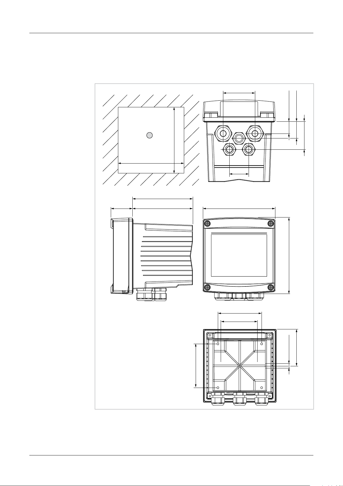
66 mm/2.59"
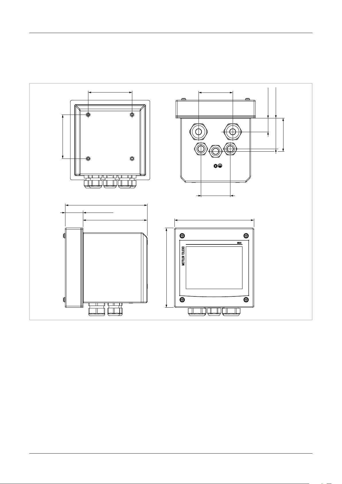
4.2 Mounting 1/2 DIN Versions (PC housing)
4.2.1 Dimensions 1/2 DIN Version (PC housing)
25 mm/0.98”
35 mm/1.38”
+0.5 mm
+0.02"
5.39"
137 mm
58 mm/2.28”
40 mm/
1.58"
137 mm
5.39"
1
+0.5 mm
+0.02"
45 mm/
1.77"
170 mm/6.69"
125 mm/4.92"
METTLER TOLEDO
35 mm/
1.38"
150 mm/5.9"
90 mm/3.54"
80 mm/3.15"
M800
158 mm/6.22"
6 mm/0.236"
75 mm/2.95"
90 mm/3.54"
Fig. 3: Dimensions 1/2 DIN version (PC housing)
1 Dimensions for panel coutout
© 05/2019 Mettler-Toledo GmbH, CH-8606 Greifensee, Switzerland Transmitter M800
Printed in Switzerland 52 121 825 D
Page 25

Transmitter M800 25
1
2
3
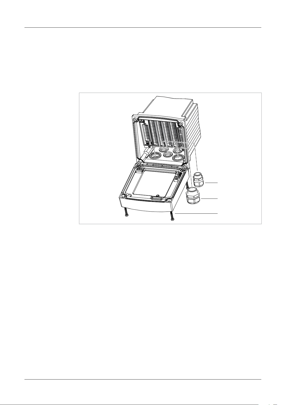
4.2.2 Mounting Procedure – 1/2 DIN Version (PC housing)
1/2 DIN versions transmitters are designed for the following mounting versions: panal mount,
wall mount or pipe mount. For wall mount the integral rear cover is used.
Optional hardware accessories are available that allow for panel- or pipe-mount.
Refer to section „14.2 Accessories and Spare Parts“.
Assembly
Fig. 4: Assembly – 1/2 DIN version (PC housing)
1 1 piece M25 x 1.5 cable gland
2 4 pieces M20 x 1.5 cable glands
3 4 pieces screws
General:
– Orient the transmitter so that the cable grips face downward.
– Wiring routed through the cable grips shall be suitable for use in wet locations.
– In order to provide IP66 enclosure ratings, all cable glands must be in place. Each cable
gland must be filled using a UL rated cable marked “wet”, “wet location” or “outdoor”, measuring0.36”(6.6mm)orlargerdiameter,employedwithinthespecifiedstrainreliefclamping range. Do not use metal conduit.
– Tightenthescrewsofthefrontpanelwithatighteningtorqueof2Nm.
© 05/2019 Mettler-Toledo GmbH, CH-8606 Greifensee, Switzerland Transmitter M800
Printed in Switzerland 52 121 825 D
Page 26
Transmitter M800 26
4.2.3 1/2 DIN Version (PC housing) – Panel Mounting
To insure a good seal, the panel or door must be flat and have a smooth finish. Textured or
rough surfaces are not recommended and may limit the effectiveness of the gasket seal provided.
1. Make cutout in panel. For dimensions refer to 4.2.1 “Dimensions 1/2 DIN Version (PC
housing)”.
– Be sure surface surrounding cutout is clean, smooth and free of burrs.
2. Slide face gasket around transmitter from the back of the unit.
3. Place transmitter into cutout hole. Be sure there are no gaps between the transmitter
and panel surface.
4. Place the two mounting brackets on either side of the transmitter as shown.
5. While holding transmitter firmly into the cutout hole, push the mounting brackets toward
the backside of panel.
6. Once secure, use a screwdriver to tighten the brackets against the panel. In order to pro-
vide IP66 environmental enclosure rating, the two clamps provided shall be securely tight-
enedtocreateanadequatesealbetweenthepanelenclosureandtransmitter.
– Face gasket will compress between transmitter and panel.
a
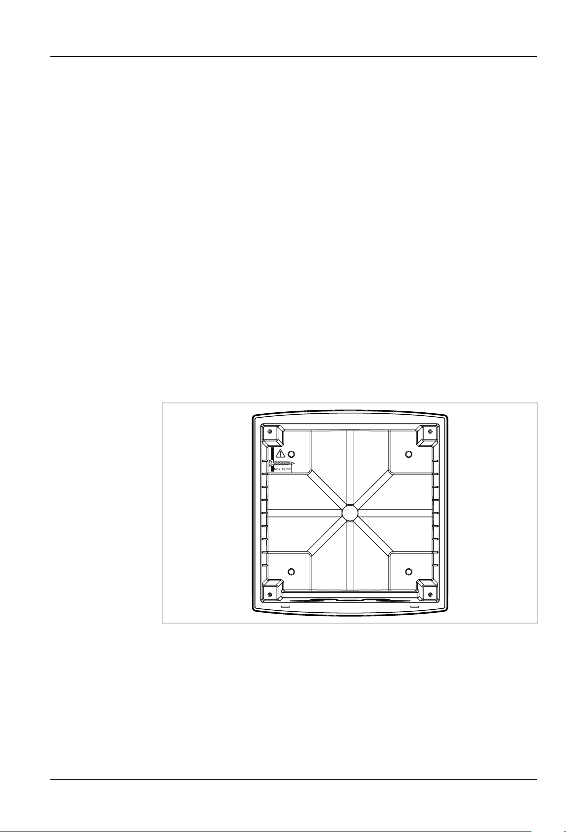
4.2.4 1/2 DIN Version – Wall Mounting
DANGER! Mortal danger by electric shock or risk of electrical shock:Themaximumscrew-in
depthofthemountingholesinthehousingis12mm(0.47inch).Donotexceedmaximum
screw-in depth.
Fig. 5: Maximum screw-in depth
© 05/2019 Mettler-Toledo GmbH, CH-8606 Greifensee, Switzerland Transmitter M800
Printed in Switzerland 52 121 825 D
Page 27
Transmitter M800 27
∅ 40 … ∅ 60 mm
1. Mount wall mounting kit to the housing. Do not exceed maximum screw-in depth.
2. Mount wall mounting kit with the housing to the wall.
Attach to wall using appropriate mounting hardware for wall surface. Be sure it is level and
securely fastened and the installation adheres to any and all clearance dimensions re-
quiredfortransmitterserviceandmaintenance.Orientthetransmittersothatthecable
grips are facing downward.
Fig. 6: Wall mounting with wall mounting kit – 1/2 DIN version (PC housing)
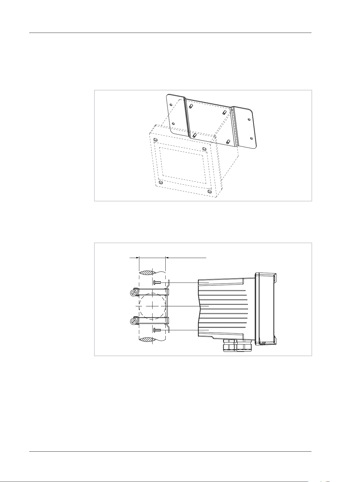
4.2.5 1/2 DIN Version (PC housing) – Pipe Mounting
∅ 1.57 … ∅ 2.36"
Fig. 7: Pipe mounting – 1/2 DIN version (PC version)
– Use only manufacturer-supplied components for pipe-mounting the M800 transmitter. See
section „14.2 Accessories and Spare Parts“ for ordering information.
– Tightenthefixingscrewswithatighteningtorqueof2to3Nm.
© 05/2019 Mettler-Toledo GmbH, CH-8606 Greifensee, Switzerland Transmitter M800
Printed in Switzerland 52 121 825 D
Page 28
Transmitter M800 28
90 mm/3.54"
90 mm/3.54" 70 mm/2.76"
4.3 Mounting Stainless Steel Version
4.3.1 Dimensions Stainless Steel Version
28 mm/1.10"
63 mm/2.48"
68 mm/2.68"
60 mm/2.36"
168 mm/6.61"
37 mm/1.46"
131 mm/5.16"
163 mm/6.42"
163 mm/6.42"
Fig. 8: Dimensions stainless steel version
© 05/2019 Mettler-Toledo GmbH, CH-8606 Greifensee, Switzerland Transmitter M800
Printed in Switzerland 52 121 825 D
Page 29
Transmitter M800 29
1
2
3
4.3.2 Mounting Procedure – Stainless Steel Version
Stainless steel versions transmitters are designed for the following mounting versions: wall
mount or pipe mount. For wall mount the integral rear cover is used.
Optional hardware accessories are available that allow for pipe-mount.
Refer to section „14.2 Accessories and Spare Parts“.
Assembly
Fig. 9: Assembly – stainless steel version
1 1 piece M25 x 1.5 cable gland
2 4 pieces M20 x 1.5 cable glands
3 4 pieces screws
General:
– Orient the transmitter so that the cable grips face downward.
– Wiring routed through the cable grips shall be suitable for use in wet locations.
– In order to provide IP66 enclosure ratings, all cable glands must be in place. In order to pro-
vide IP66 enclosure ratings, all cable glands must be in place. Each cable gland must be
filled using a UL rated cable marked “wet”, “wet location” or “outdoor”, measuring 0.36”
(6.6mm)orlargerdiameter,employedwithinthespecifiedstrainreliefclampingrange.Do
not use metal conduit.
© 05/2019 Mettler-Toledo GmbH, CH-8606 Greifensee, Switzerland Transmitter M800
Printed in Switzerland 52 121 825 D
Page 30

Transmitter M800 30
∅ 40 … ∅ 60 mm
4.3.3 Stainless Steel Version – Wall Mounting
1. Mount wall mounting kit to the housing. Do not exceed maximum screw-in depth.
2. Mount wall mounting kit with the housing to the wall.
Attach to wall using appropriate mounting hardware for wall surface. Be sure it is level and
securely fastened and the installation adheres to any and all clearance dimensions re-
quiredfortransmitterserviceandmaintenance.Orientthetransmittersothatthecable
grips are facing downward.
Fig. 10: Wall mounting with wall mounting kit – stainless steel version (PC housing)
4.3.4 Stainless Steel Version – Pipe Mounting
∅ 1.57 … ∅ 2.36"
Fig. 11: Pipe mounting – stainless steel version
– Use only manufacturer-supplied components for pipe-mounting the M800 transmitter. See
section „14.2 Accessories and Spare Parts“ for ordering information.
© 05/2019 Mettler-Toledo GmbH, CH-8606 Greifensee, Switzerland Transmitter M800
Printed in Switzerland 52 121 825 D
Page 31

Transmitter M800 31
4.4 Electrical Connection
DANGER! Mortal danger by electric shock:Poweroffinstrumentduringelectricalconnection.
a
NOTE: This is a 4-wire-product with an active 4–20 mA analog output.
h
Do not supply power to the analog output terminals (Aout). These are terminals 3 to 10
of TB1 and additionally, for 2-channel and 4-channel version terminals 1 to 8 of TB3.
The terminals are placed inside the housing.
AllM800transmittersaredesignedtooperatefroma20to30VDCora100to240VAC
powersource.Refertospecificationsforpowerrequirementsandratingsandsizepowerwiring
accordingly.
The terminals are suitable for single wires and flexible leads with a wire cross-section from
0.2 mm2 up to 1.5 mm2, (16–24 AWG).
1. Switch off supply voltage.
2. Connect mains supply as follows:
– 20to30VDC:N (–) for Neutral and L (+) for Line
1-channel versions to terminal TB5, 2-channel or 4-channel versions to terminal TB6
– 100to240VAC:N for Neutral and L for Line
1-channel versions to terminal TB5, 2-channel or 4-channel versions to terminal TB6.
3. For stainless steel version: Connect protective earth to the PE terminal according to Fig. 12
on Page 31. The cross-section of the PE wire must be above 0.8 mm
4. Connect sensor, analog output signals, digital input signals and relay output signals ac-
cording to chapter „4.5 Terminal Definition“.
5. For stainless steel version: Secure that the internal ground wiring between housing and
front cover is securely connected.
2
(18 AWG).
a
DANGER! Mortal danger by electric shock:Forstainlesssteelhousingconnect protective earth
to the PE terminal. Secure that the internal ground wiring between housing and front cover is
securely connected.
2
1
Fig. 12: Connection of protective earth to PE terminal and internal ground wiring
1 PE terminal for protective earth
2 Terminal for internal ground wiring between housing and front cover
© 05/2019 Mettler-Toledo GmbH, CH-8606 Greifensee, Switzerland Transmitter M800
Printed in Switzerland 52 121 825 D
Page 32

Transmitter M800 32
4.5 TerminalDenition
4.5.1 M800 1-Channel
Power connections: N (–) for Neutral and L(+) for Line for 20 to 30 VDC. N for Neutral and L for
Linefor100to240VAC.
For stainless steel version: Connect protective earth to the PE terminal according to Fig. 12 on
Page 31.
Terminal number TB1 TB2 TB3 TB4 TB5
L (+)
N (–)
Ground
1 DI1+ 1-Wire AI1+ Relay1_NC
2 DI1– GND5V AI1- Relay1_COM
3 Aout1+ RS485B DI4+ Relay2_NO
4 Aout1– RS485A DI4– Relay2_COM
5 Aout2+ GND5V DI5+ Relay3_NO
6 Aout2– 5V DI5– Relay3_COM
7 Aout3+ 24V DI6+ Relay4_NO
8 Aout3– GND24V DI6– Relay4_COM
9 Aout4+ n. a. Relay5_NO n. a.
10 Aout4– n. a. Relay5_COM n. a.
11 n. a. n. a. Relay6_NO n. a.
12 n. a. n. a. Relay6_COM n. a.
13 n. a. n. a. Relay7_NO n. a.
14 n. a. n. a. Relay7_COM n. a.
15 n. a. n. a. Relay8_NC n. a.
16 n. a. n. a. Relay8_COM n. a.
For analog
sensors sensorspecific.
For ISM sensors
not used.
TB2
TB1
RECEIVER
TB3
TB4
TB5
EMITTER
NO: normally open (contact open if un-actuated).
NC: normally closed (contact closed if un-actuated).
n.a. not available
NOTE: This is a 4-wire-product with an active 4–20 mA analog output.
h
© 05/2019 Mettler-Toledo GmbH, CH-8606 Greifensee, Switzerland Transmitter M800
Printed in Switzerland 52 121 825 D
Please do not supply power to terminal no. 3 to 10 of TB1.
Page 33

Transmitter M800 33
4.5.1.1 InPro8000 Series Turbidity Sensor
Use the two connections labeled EMITTER and RECEIVER for connecting METTLER TOLEDO
InPro8000sensorsonly.Patchcordsareavailableupto170m(558ft)inlength.Mismatching the two ends of a sensor cable is not possible. Only hand-screwed fixing of the two SMA
connectors of the sensor cable on the transmitter connectors is recommended.
CAUTION: Do not cut or shorten fiber optic cables. Cutting of fiber optic cables and assembly of
a
SMAconnectorsrequirespecialtools.Whereitisdesiredtouseshorterpatchcables,consult
your METTLER TOLEDO supplier.
See the appropriate sensor instruction manual for detailed information regarding installation and
specific use of fiber optic sensors.
© 05/2019 Mettler-Toledo GmbH, CH-8606 Greifensee, Switzerland Transmitter M800
Printed in Switzerland 52 121 825 D
Page 34

Transmitter M800 34
4.5.2 M800 2-Channel
Power connections: N (–) for Neutral and L (+) for Line for 20 to 30 VDC. N for Neutral and L
forLinefor100to240VAC.
For stainless steel version: Connect protective earth to the PE terminal according to Fig. 12 on
Page 31.
Terminal
number
1 DI1+ DI2+ Aout5+ AI1+ Relay1_NC
2 DI1– DI2– Aout5– AI1- Relay1_COM
3 Aout1+ 1-Wire_Ch1 Aout6+ DI4+ Relay2_NO
4 Aout1– GND5V_Ch1 Aout6– DI4– Relay2_COM
5 Aout2+ RS485B_Ch1 Aout7+ DI5+ Relay3_NO
6 Aout2– RS485A_Ch1 Aout7– DI5– Relay3_COM
7 Aout3+ GND5V_Ch1 Aout8+ DI6+ Relay4_NO
8 Aout3– 5V_Ch1 Aout8- DI6– Relay4_COM
9 Aout4+ 24V_Ch2 Ain_Ch3 Relay5_NO n. a.
10 Aout4– GND24V_Ch2 AJ_Ch3 Relay5_COM n. a.
11 n. a. 1-Wire_Ch2 5V_Ch3 Relay6_NO n. a.
12 n. a. GND5V_Ch2 GND5V_Ch3 Relay6_COM n. a.
13 n. a. RS485B_Ch2 Bin_Ch4 Relay7_NO n. a.
14 n. a. RS485A_Ch2 BJ_Ch4 Relay7_COM n. a.
15 n. a. GND5V_Ch2 5V_Ch4 Relay8_NO n. a.
16 n. a. 5V_Ch2 GND5V_Ch4 Relay8_COM n. a.
TB1
TB2
(ISM Ch1,2)
TB3 TB4 TB5 TB6
L (+)
N (–)
Ground
Not installed
TB2 TB3
TB1
TB4
TB5
TB6
NO: normally open (contact open if un-actuated).
NC: normally closed (contact closed if un-actuated).
n.a. not available
NOTE: This is a 4-wire-product with an active 4–20 mA analog output.
h
Please do not supply power to terminal no. 3 to 10 of TB1 and 1 to 8 of TB3.
© 05/2019 Mettler-Toledo GmbH, CH-8606 Greifensee, Switzerland Transmitter M800
Printed in Switzerland 52 121 825 D
Page 35

Transmitter M800 35
4.5.3 M800 4-Channel
Power connections: N (–) for Neutral and L (+) for Line for 20 to 30 VDC. N for Neutral and L
forLinefor100to240VAC.
For stainless steel version: Connect protective earth to the PE terminal according to Fig. 12 on
Page 31.
Terminal
number
1 DI1+ DI2+ Aout5+ DI3+ AI1+ Relay1_NC
2 DI1– DI2– Aout5– DI3– AI1- Relay1_COM
3 Aout1+ 1-Wire_Ch1 Aout6+ 1-Wire_Ch3 DI4+ Relay2_NO
4 Aout1– GND5V_Ch1 Aout6– GND5V_Ch3 DI4– Relay2_COM
5 Aout2+ RS485B_Ch1 Aout7+ RS485B_Ch3 DI5+ Relay3_NO
6 Aout2– RS485A_Ch1 Aout7– RS485A_Ch3 DI5– Relay3_COM
7 Aout3+ GND5V_Ch1 Aout8+ GND5V_Ch3 DI6+ Relay4_NO
8 Aout3– 5V_Ch1 Aout8- 5V_Ch3 DI6– Relay4_COM
9 Aout4+ 24V_Ch2 Ain_Ch5 24V_Ch4 Relay5_NO n. a.
10 Aout4– GND24V_Ch2 AJ_Ch5 GND24V_Ch4 Relay5_COM n. a.
11 n. a. 1-Wire_Ch2 5V_Ch5 1-Wire_Ch4 Relay6_NO n. a.
12 n. a. GND5V_Ch2 GND5V_Ch5 GND5V_Ch4 Relay6_COM n. a.
13 n. a. RS485B_Ch2 Bin_Ch6 RS485B_Ch4 Relay7_NO n. a.
14 n. a. RS485A_Ch2 BJ_Ch6 RS485A_Ch4 Relay7_COM n. a.
15 n. a. GND5V_Ch2 5V_Ch6 GND5V_Ch4 Relay8_NC n. a.
16 n. a. 5V_Ch2 GND5V_Ch6 5V_Ch4 Relay8_COM n. a.
TB1
TB2
(ISM Ch1,2)
TB3
TB4
(ISM Ch3,4)
TB5 TB6
L (+)
N (–)
Ground
TB2
TB3 TB4 TB5
TB1
TB6
NO: normally open (contact open if un-actuated).
NC: normally closed (contact closed if un-actuated).
n.a. not available
NOTE: This is a 4-wire-product with an active 4–20 mA analog output.
h
Please do not supply power to terminal no. 3 to 10 of TB1 and 1 to 8 of TB3.
© 05/2019 Mettler-Toledo GmbH, CH-8606 Greifensee, Switzerland Transmitter M800
Printed in Switzerland 52 121 825 D
Page 36

Transmitter M800 36
4.5.4 M800 1-Channel: TB2 – Conductivity 2e/4e Analog Sensors
Cond 4-E or 2-E
Terminal Function Color
1
2
3
4
5
6
7
8
9
10
11
12
13
14
15
16
Cnd inner1
Not used –
Cnd outer1
Cnd outer1 –
Not used –
Cnd outer2 –
Cnd inner2
Cnd outer2 (GND)
Not used –
Not used –
Not used –
RTD ret/GND bare shield
RTD sense red
RTD green
Not used –
5V output –
1)
1)
2)
2)
white
white/blue
blue
black
1) ForthirdpartyCond2esensorsajumperbetween1and3mayberequired.
2) ForthirdpartyCond2esensorsajumperbetween7and8mayberequired.
4.5.5 M800 1-Channel: TB2 – pH/ORP Analog Sensors
pH Redox (ORP)
Terminal Function Color 1
1
2
3
4
5
6
7
8
9
10
11
12
13
14
15
16
Glass transparent Platinum transparent
Not used – – –
Not used – – –
Not used – – –
Not used – – –
Reference red Reference red
Reference
Solution GND
2)
– Reference
2)
blue
Not used –
Shield (GND) green/yellow Shield (GND) green/yellow
Not used – – –
RTD ret/GND white – –
RTD sense – – –
RTD green
Not used – – –
5 V output – – –
1)
3)
Function Color
2)
Solution GND
–
2)
–
1) Grey wire not used.
2) Install jumper between 7 and 8 for ORP sensors and pH electrodes without SG.
3) Blue wire for electrode with SG.
© 05/2019 Mettler-Toledo GmbH, CH-8606 Greifensee, Switzerland Transmitter M800
Printed in Switzerland 52 121 825 D
Page 37

Transmitter M800 37
4.5.6 M800 1-Channel: TB2 – Oxygen Analog Sensors
InPro6800 InPro6900 InPro6950
Terminal Function Color Color Color
1
2
3
4
5
6
7
8
9
10
11
12
13
14
15
16
Not used – – –
Not used – – –
Anode red red red
Anode –
Reference –
1)
1)
1)
–
1)
–
–
blue
Not used – – –
Not used – – –
Guard – grey grey
Cathode transparent transparent transparent
Shield (GND) green/yellow green/yellow green/yellow
Not used – – –
NTC ret (GND) white white white
Not used – – –
NTC green green green
Not used – – –
5 V output – – –
1) Install jumper between 4 and 5 for InPro6800 and InPro6900.
© 05/2019 Mettler-Toledo GmbH, CH-8606 Greifensee, Switzerland Transmitter M800
Printed in Switzerland 52 121 825 D
Page 38

Transmitter M800 38
4.5.7 M800 2- and 4-Channel: TB2 and TB4 – Terminal
Assignment for Optical Oxygen, CO
hi, UniCond2e,
2
UniCond4e and 5000TOCi ISM Sensors
TB2
(ISM Ch1,2)
Terminal Function Function
1 DI2+ DI6+ – – –
2 DI2– DI6- – – –
3 1-Wire_Ch1 1-Wire_Ch3 – – –
4 GND5V_Ch1 GND5V_Ch3 – – –
5 RS485B_Ch1 RS485B_Ch3 – – black
6 RS485A_Ch1 RS485A_Ch3 – – red
7 GND5V_Ch1 GND5V_Ch3 – – white
8 5V_Ch1 5V_Ch3 – – blue
9 24V_Ch2 24V_Ch4 grey brown –
10 GND24V_Ch2 GND24V_Ch4 blue black –
11 1-Wire_Ch2 1-Wire_Ch4 – – –
12 GND5V_Ch2 GND5V_Ch4 green/yellow grey –
13 RS485B_Ch2 RS485B_Ch4 brown blue black
14 RS485A_Ch2 RS485A_Ch4 pink white red
15 GND5V_Ch2 GND5V_Ch4 – yellow white
16 5V_Ch2 5V_Ch4 – – blue
TB4
(ISM Ch3,4)
Optical Oxygen 1), CO2 hi
VP8 cables
wire color
5-pin cables
wire color
UniCond2e
1)
UniCond4e 2),
5000TOCi
Cables
wire color
2),
1) One O2 optical or thermal conductivity CO2 sensor can be connected to plug TB2 and TB4.
2) Transparent wire not connected.
© 05/2019 Mettler-Toledo GmbH, CH-8606 Greifensee, Switzerland Transmitter M800
Printed in Switzerland 52 121 825 D
Page 39

Transmitter M800 39
4.5.8 M800 2- and 4-Channel: TB2 and TB4 – Terminal
Assignment for pH, Amp. Oxygen, Cond 4e, CO
O
ISM Sensors
3
TB2
(ISM Ch1,2)
Terminal Function Function Cables wire color
1 DI2+ DI6+ –
2 DI2– DI6– –
3 1-Wire_Ch1 1-Wire_Ch3 transparent (cable core)
4 GND5V_Ch1 GND5V_Ch3 red
5 RS485B_Ch1 RS485B_Ch3 –
6 RS485A_Ch1 RS485A_Ch3 –
7 GND5V_Ch1 GND5V_Ch3 –
8 5V_Ch1 5V_Ch3 –
9 24V 24V –
10 GND24V GND24V –
11 1-Wire_Ch2 1-Wire_Ch4 transparent (cable core)
12 GND5V_Ch2 GND5V_Ch4 red
13 RS485B_Ch2 RS485B_Ch4 –
14 RS485A_Ch2 RS485A_Ch4 –
15 GND5V_Ch2 GND5V_Ch4 –
16 5V_Ch2 5V_Ch4 –
TB4
(ISM Ch3,4)
pH, Amp. Oxygen,
Cond 4e, CO2 and O
and
2
3
© 05/2019 Mettler-Toledo GmbH, CH-8606 Greifensee, Switzerland Transmitter M800
Printed in Switzerland 52 121 825 D
Page 40

Transmitter M800 40
4.5.9 M800 1-Channel: TB3 – Terminal Assignment for
Optical Oxygen, CO
hi, UniCond2e and UniCond4e
2
ISM Sensors
TB3 Optical Oxygen, CO2 hi
Terminal Function
1 1-Wire – – –
2 GND5V – yellow –
3 RS485B brown blue black
4 RS485A pink white red
5 GND5V green/yellow grey white
6 5V – – blue
7 24V grey brown –
8 GND24V blue black –
9 Not used – – –
10 Not used – – –
11 Not used – – –
12 Not used – – –
13 Not used – – –
14 Not used – – –
15 Not used – – –
16 Not used – – –
VP8 cables
wire color
5-pin cables
wire color
UniCond2e 1),
UniCond4e
Cables
wire color
1)
1) Transparent wire not connected.
© 05/2019 Mettler-Toledo GmbH, CH-8606 Greifensee, Switzerland Transmitter M800
Printed in Switzerland 52 121 825 D
Page 41

Transmitter M800 41
4.5.10 M800 1-Channel: TB3 – Terminal Assignment for pH and Turbidity ISM Sensors
TB3
Terminal Function
1 1-Wire transparent (cable core)
2 GND5V red green/yellow
3 RS485B – green
4 RS485A – yellow
5 GND5V – –
6 5V – –
7 24V – brown
8 GND24V – white
9 Not used – –
10 Not used – –
11 Not used – –
12 Not used – –
13 Not used – –
14 Not used – –
15 Not used – –
16 Not used – –
pH, Amp. Oxygen, CO2
and Cond 4e
Cables:
wire color
Turbidity (InPro8600i/D1,
InPro8600i/D3)
Cables:
wire color
1) Transparent wire not connected.
4.5.11 M800 2- and 4-Channel Water: TB3 – Terminal Assignment for Flow Sensors
TB3
Terminal Transmitter Function
1 Aout5+ –
2 Aout5- –
3 Aout6+ –
4 Aout6- –
5 Aout7+ –
6 Aout7- –
7 Aout8+ –
8 Aout8- –
9 Ain_Ch3 / Ain_Ch5 Flow Pulse Input
10 AJ_Ch3 / AJ_Ch5 + 10 VDC
11 5V_Ch3 / 5V_Ch5 + 5 VDC
12 GND5V_Ch3 / GND5V_Ch5 Ground
13 Ain_Ch4 / Ain_Ch6 Flow Pulse Input
14 AJ_Ch4 / AJ_Ch6 + 10 VDC
15 5V_Ch4 / 5V_Ch6 + 5 VDC
16 GND5V_Ch4 / GND5V_Ch6 Ground
Flow hi, Flow lo, Flow
Type2
© 05/2019 Mettler-Toledo GmbH, CH-8606 Greifensee, Switzerland Transmitter M800
Printed in Switzerland 52 121 825 D
Page 42

Transmitter M800 42
4.6 Connection of Flow Sensor
The M800 Transmitter is designed to operate with various types of sensors. These sensors re-
quiredifferentwiringconfigurations.Listedbelowareinstructionsforwiringthevarioustypesof
sensors offered by METTLER TOLEDO Thornton for use with this transmitter. Please consult the
factory for assistance if attempting to wire sensors not offered by METTLER TOLEDO Thornton as
some sensors may not be compatible.
4.6.1 Flow Sensor Input Wiring Kit
This kit contains components that may be needed at input terminals to condition sensor signals.
Refer to the following sections or to the instruction manual for wiring details.
4.6.2 Kit Contents
This kit contains the following items:
− 4xWirenuts
− 4x10KohmresistorsforusewithBurket8020and8030typesensors,andGFSignet
2500-series sensors.
− 4x1KohmresistorsforusewithDataIndustrial200-seriesandFluidyneinsertiontype
sensors.
− 4x0.33uF,50VcapacitorsforusewithBerket8020and8030typesensors,DataIndustrial
200-series and 4000-series sensors, GF Signet 2500-series sensors, Sanitary Turbine-Type
sensors, Fluidyne insertion type sensors and Racine Federated (Formerly Asahi/America) vortex-style sensors.
4.6.3 Flow sensor wiring for Compatible Sensors
The following sections provide wiring information to properly connect various compatible flow
sensors to the M800 Transmitter. When using the Configuration menu of the transmitter to setup
the flow sensor, the first prompt asks to select the TYPE of flow sensor being connected.
There are three choices as follows:
High: All flow sensors described in Section 4.4.4
Low: P515 Signet flow sensors only, described in section 4.4.5
Type 2: Asahi flow sensors, described in Section 4.4.6
© 05/2019 Mettler-Toledo GmbH, CH-8606 Greifensee, Switzerland Transmitter M800
Printed in Switzerland 52 121 825 D
Page 43

Transmitter M800 43
4.6.4 Wiringfor”HIGH”typeowsensors
The following wiring information is used when connecting (Burkert 8020 and 8030 type) inline
Hall effect 5VDC, flow sensors. THORNTON models 33901 thru 33935.
THORNTON 33901-33935
58 034 601 - 58 034 635
Pulse output
L+
L–
Burkert 8020, 8030
Hall-Effect Sensor
Type: high
0.33uF
10K
Extension cable not provided. Use 2-conductor twisted pair with shield, 22 AWG (Belden 8451
orequivalent),1,000ft(305m)maximumlength.
The following wiring information is used when connecting Badger (formerly Data Industrial
200-Series) forward-swept paddlewheel type flow sensors.
THORNTON models 33142 thru 33145 and 33159 thru 33162 and 33273.
TB 3
9 Ain_Ch5
10 AJ_Ch5
11 5V_Ch5
12 GND5V_Ch5
M800 transmitter
THORNTON 33142-33145
Red
Black
Shield
(formerly Data Industrial 200 Series)
Badger
Flow Sensors
Type: High
58 034 201 - 58 034 204
0.33uF
1K
TB 3
9 Ain_Ch5
10 AJ_Ch5
11 5V_Ch5
12 GND5V_Ch5
M800 transmitter
Extension cable provided with sensor. Use 2-conductor twisted pair with shield 20 AWG
(Belden9320orequivalent)toextendlengthto2000ft(610m)max.
The following wiring information is used when connecting Badger (formerly Data Industrial
4000-Series) forward-swept paddlewheel type flow sensors.
THORNTON models 33174 thru 33177 and 33171 and 33172.
THORNTON 33174-33177, 33171, 33172
58 034 207 - 58 034 211, 58 034 226
Clear
Red
Black
Shield
(formerly Data Industrial 4000 Series)
Badger
Flow Sensors
Type: High
0.33uF
TB 3
9 Ain_Ch5
10 AJ_Ch5
11 5V_Ch5
12 GND5V_Ch5
M800 transmitter
20 ft (6.1 m) extension cable provided with sensor. Use 3-conductor with shield,
20AWG(Belden9364orequivalent)toextendlengthto2000ft(610m)maximum.
© 05/2019 Mettler-Toledo GmbH, CH-8606 Greifensee, Switzerland Transmitter M800
Printed in Switzerland 52 121 825 D
Page 44

Transmitter M800 44
The following wiring information is used when connecting (GF Signet 2500-Series) Hall Effect
paddlewheel type flow sensors. THORNTON models 33282, 33285, 33287, 33298 thru
33305.
THORNTON 33282, 33285, 33287, 33298 - 33305
58 034 227, 58 034 230, 58 034 232 - 58 034 240
TB 3
9 Ain_Ch5
10 AJ_Ch5
11 5V_Ch5
12 GND5V_Ch5
M800 transmitter
Signet 2507, 2536, 2540
Hall-Effect Sensor
Type: high
Red
Black
Shield
0.33uF
10K
25 ft (7.6 m) extension cable provided with sensor. Use 2-conductor with shield,
22AWG(Belden8451orequivalent)toextendlengthto1000ft(305m)maximum.
The following wiring information is used when connecting Sanitary Turbine type flow sensors.
THORNTON models 33336 thru 33377 (Hoffer) and 33441 thru 33450 (Sponsler).
THORNTON 3336-33348, 33376, 33377
58 034 270 - 58 034 282, 58 034 303, 58 034 304
TB 3
9 Ain_Ch5
10 AJ_Ch5
11 5V_Ch5
12 GND5V_Ch5
M800 transmitter
Hoffer Turbine Sensors
Type: High
White
Red
Black
Shield
0.33uF
20 ft (6.1 m) extension cable provided with sensor. Use 3-conductor with shield,
20AWG(Belden9364orequivalent)toextendlengthto3000ft(915m)maximum.
THORNTON 33441-33450
Sponsler Turbine Sensor
Type: High
58 034 516 - 58 034 525
Orange
Red
Black
Shield
0.33uF
TB 3
9 Ain_Ch5
10 AJ_Ch5
11 5V_Ch5
12 GND5V_Ch5
M800 transmitter
20 ft (6.1 m) extension cable provided with sensor. Use 3-conductor with shield,
20AWG(Belden9364orequivalent)toextendlengthto3000ft(915m)maximum.
© 05/2019 Mettler-Toledo GmbH, CH-8606 Greifensee, Switzerland Transmitter M800
Printed in Switzerland 52 121 825 D
Page 45

Transmitter M800 45
The following wiring information is used when connecting Spirax Sarco/Emco flow (formerly
Fluidyne) insertion type flow sensors. THORNTON models 33358 thru 33375.
THORNTON 33358 - 33375
Spirax Sarco/Emco flow
(formerly Fluidyne)
Insertion Vortex Sensor
Type: High
58 034 285 - 58 034 302
(+)
(–)
Shield
0.33uF
1K
TB 3
9 Ain_Ch5
10 AJ_Ch5
11 5V_Ch5
12 GND5V_Ch5
M800 transmitter
Extension cable not provided. Use 2-conductor twisted pair with shield, 20 AWG (Belden 9320
orequivalent),2000ft(610m)maximumlength.
4.6.5 Wiringfor”LOW”typeowsensors
The following wiring information is used when connecting (GF Signet 515) type flow sensors.
THORNTON models 33189, 33193, 33195, 33196, and 33229.
THORNTON 33189, 33193, 33195, 33196, 33229
58 034 215 , 58 034 219, 58 034 221, 58 034 222, 58 034 224
TB 3
Red
Black
Shield
Signet 515 Sensor
Type: low
9 Ain_Ch5
10 AJ_Ch5
11 5V_Ch5
12 GND5V_Ch5
M800 transmitter
Extension cable not provided. Use 2-conductor twisted pair with shield, 22 AWG (Belden 8451
orequivalent,200ft(61m)maximumlength.
4.6.6 Wiringfor”TYPE2”owsensors
The following wiring information is used when connecting Racine Federated (formerly Asahi/
America) vortex flow sensors. THORNTON models 33308 to 33335.
THORNTON 33308-33335
58 034 242 - 58 034 265
TB 3
9 Ain_Ch5
10 AJ_Ch5
11 5V_Ch5
12 GND5V_Ch5
M800 transmitter
Racine Federated
(formerly Asahi/America)
Vortex Sensor
Type: 2
Signal
(+)Power
(-)Ground
0.33uF
Extensioncablenotprovided.Use3-conductorwithshield,20AWG(Belden9364orequivalent), 1000 ft (305 m) maximum length.
© 05/2019 Mettler-Toledo GmbH, CH-8606 Greifensee, Switzerland Transmitter M800
Printed in Switzerland 52 121 825 D
Page 46

Transmitter M800 46
5 Placing transmitter in, or out, of service
5.1 Placing transmitter in service
After connecting the transmitter to power supply circuit, it will be active as soon as the circuit is
powered.
a
5.2 Placing transmitter out of service
First disconnect the unit from the main power source, then disconnect all remaining electrical
connections. Remove the unit from the panel. Use the installations instruction in this manual as
reference for dis-assembling mounting hardware.
All transmitter settings stored in memory are non volatile.
© 05/2019 Mettler-Toledo GmbH, CH-8606 Greifensee, Switzerland Transmitter M800
Printed in Switzerland 52 121 825 D
Page 47

Transmitter M800 47
6 Guided Setup
PATH: H \ CONFIG \ Guided Setup
NOTE: Please do not use Guided Setup menu after configuration of the transmitter, because
h
NOTE: If the guided setup for a flow sensor has been selected, the calibration factor of the sensor
h
some of the settings (i.e. analog output configuration) will be set to default values again.
See the following explanation to get more details about the different settings for the guided setup.
Select the desired Channel for the guided setup and in the same line the parameter.
If Auto is selected, M800 Transmitter automatically recognizes the type of sensor. The channel
can also be fixed to a certain measurement parameter, depending on the type of trans mitter. For
detailed information refer to chapter 8.1.1 “Channel Setup”.
Press the corresponding button to measurement M1 to configure the measurement. For detailed
information about the configuration options refer to chapter 8.1.1 “Channel Setup”.
from the sensor label or certificate can be entered. Therefore press the Cal Factor button. For sensor types High and Low slope and offset can be entered. In case of sensor Type 2 the slope followed by a table of K and F values can be entered.
Assign the corresponding output signal Aout’X’ to the measurement by pressing Yes. For detailed information about the configuration of the analog output signal refer to chapter 8.3 “Analog Outputs”.
Enter the Min Value, that corresponds with start point of the analog output range.
Enter the Max Value , that corresponds with end point of the analog output signal.
Additional settings can be done by navigating to the next page of the menu.
Assigning the corresponding Set Point’X’ to the measurement by pressing Yes. For detailed in-
formation about the configuration of the set point refer to chapter 8.4 “Set Points”.
Select the Type for the setpoint.
The type of the setpoint can be High, Low, Between, Outside or Off. An ”Outside” setpoint will
cause an alarm condition whenever the measurement goes above its high limit or below its low
limit. A ”Between” setpoint will cause an alarm condition to occur whenever the measurement is
between its high and low limits.
NOTE: If the type of set point is not Off additional settings can be done. See the following de-
h
scription.
According to the selected type of set point, value(s) according to the limit(s) can be entered.
Select the desired relay that will be activated if the defined conditions are reached through the
parameter SP Relay. If the chosen relay is used for another task, the transmitter shows a message on the screen that there is a Relay Conflict.
To escape the menu of the settings for Guided Setup press p. To return to the Menu Screen (see
chapter 3.2 “Display”) press H. The M800 will bring up the Save Changes dialog.
© 05/2019 Mettler-Toledo GmbH, CH-8606 Greifensee, Switzerland Transmitter M800
Printed in Switzerland 52 121 825 D
Page 48

Transmitter M800 48
7 Calibration
For the menu structure refer to chapter 3.4.1 “Menu Structure”.
PATH: H \ Cal
NOTE: During calibration, the outputs for the corresponding channel will default to be held at
h
NOTE: ISM sensors: “Adjust” detects deviations and readjusts the sensor. Calibration is per-
h
their current values until 20 seconds after the calibration menu is exited. A flashing H appears in
the upper right corner of the display while outputs are held. Refer to chapter 8.3 “Analog Outputs” and chapter 8.4 “Set Points” to change the HOLD output status.
formed and calculated values are stored in the sensor. “Calibrate” detects deviations and does
not readjust the sensor. Calibration is not performed, but calculated values are stored in the sensor.
Analog sensors: “SaveCal” performs calibration.The actual values can be viewed as long as the
sensor is connected.
7.1 Sensor Calibration
PATH: H \ Cal \ Calibrate Sensor
Select the desired channel (Chan) for calibration.
NOTE:Duringsensorcalibration,theoutputswilldefaulttheircurrentvaluesuntil20secondsaf-
h
ter the calibration menu is exited. A flashing H appears in the upper right corner of the display
while outputs are held. Refer to chapter 8.3 “Analog Outputs” and chapter 8.4 “Set Points” to
change the HOLD output status.
See the following explanation to get more details about the calibration options and procedure.
7.2 Calibration of UniCond2e and UniCond4e Sensors (ISM Sensors only)
7.2.1 Conductivity Calibration of UniCond2e and UniCond4e Sensors
The M800 provides the ability to perform a one-point, two-point or process conductivity or resistivity calibration for 2e-sensors and 4e-sensors.
NOTE: When performing calibration on a conductivity sensor, results will vary depending on the
h
© 05/2019 Mettler-Toledo GmbH, CH-8606 Greifensee, Switzerland Transmitter M800
Printed in Switzerland 52 121 825 D
method,calibrationapparatusand/orqualityofreferencestandardsusedtoperformthecalibration.
Page 49

Transmitter M800 49
NOTE: For measuring tasks the temperature compensation for the application as defined
h
through the parameter settings for conductivity will be considered and not the temperature compensation selected through the calibration procedure (see also chapter 8.1.4.1 “Conductivity
Settings”; PATH: H \ CONFIG \ Meas \ Parameter Setting).
Enter the menu Calibrate Sensor (see chapter 7.1 “Sensor Calibration”; PATH: H \ Cal \ Calibrate
Sensor) and choose the desired channel for calibration.
The following menus can be called up:
Unit: Choose between the units for conductivity (S/cm) and resistivity (Ω-cm).
Method: Select the desired calibration procedure. Available are 1-point, 2-point or process
calibration.
Options: The desired compensation mode for the calibration process can be selected.
Choices are “None”, ”Standard”, “Light 84”, “Std 75 °C”, ”Linear 25°C”, ”Linear
20°C”, “Glycol.5”, “Glycol1”, “Cation”, “Alcohol” and “Ammonia”.
None does not make any compensation of the measured conductivity value. The uncompen-
sated value will be displayed and proceeded.
Standard compensation includes compensation for non-linear high purity effects as well as
conventional neutral salt impurities and conforms to ASTM standards D1125 and
D5391.
Light 84 compensation matches the high purity water research results of Dr. T.S. Light pub-
lished in 1984. Use only if your institution has standardized on that work.
Std 75 °C compensation is the Standard compensation algorithm referenced to 75 °C. This
compensation may be preferred when measuring Ultrapure Water at an elevated temperature (Resistivity of ultrapure water compensated to 75 °C is
2.4818 Mohm-cm.)
Linear 25 °C compensation adjusts the reading by a coefficient or factor expressed as %/°C
(deviation from 25 °C). Use only if the solution has a well-characterized linear temperature coefficient. The factory default setting is 2.0% /°C.
2.4818 Mohm-cm.)
Linear 20 °C compensation adjusts the reading by a coefficient or factor expressed as %/°C
(deviation from 20 °C). Use only if the solution has a well-characterized linear temperature coefficient. The factory default setting is 2.0% /°C.
Glycol.5 compensation matches the temperature characteristics of 50% ethylene glycol in
water. Compensated measurements using this solution may go above
18 Mohm-cm.
Glycol1 compensation matches the temperature characteristics of 100% ethylene glycol.
Compensated measurements may go well above 18 Mohm-cm.
Cation compensation is used in power industry applications measuring the sample after a
cation exchanger. It takes into account the effects of temperature on the dissociation of
pure water in the presence of acids.
Alcohol compensation provides for the temperature characteristics of a 75% solution of iso-
propyl alcohol in pure water. Compensated measurements using this solution may go
above 18 Mohm-cm.
Ammonia compensation is used in power industry applications for specific conductivity
measured on samples using ammonia and/or ETA (ethanolamine) water treatment. It
takes into account the effects of temperature on the dissociation of pure water in the
presence of these bases.
NOTE: If compensation mode ”Linear 25 °C” or ”Linear 20 °C” has been chosen, the coefficient
h
© 05/2019 Mettler-Toledo GmbH, CH-8606 Greifensee, Switzerland Transmitter M800
Printed in Switzerland 52 121 825 D
for the adjustment of the reading can be modified. In this case an additional input field will be
displayed.
The changes are valid until the calibration mode has been escaped. After the values defined in
the configuration menu are valid again.
Page 50

Transmitter M800 50
7.2.1.1 One-Point Calibration
Select calibration procedure 1-Point (see chapter 7.2.1 “Conductivity Calibration of UniCond2e
and UniCond4e Sensors”). With 2e-sensors or 4e-sensors a one-point calibration is always performed as a slope calibration. The following procedure shows the calibration with a 2e-sensor.
The calibration with a 4e-sensor works respectively.
Press the button Cal for starting calibration.
Place the electrode in the reference solution and press Next button.
The second value displayed on the screen is the value being measured by the transmitter and
sensor in units selected by the user.
Press the input field for Point1 to enter the value for the calibration point. The M800 displays a
keypad for modifying the value. Press the e button and the transmitter will take over the value.
NOTE: To select another unit for the entered value on the keypad press the U button. To return
h
again press the 0-9 button.
The screen shows the entered value for the reference solution (1st line) and the measured value
of the M800 (2nd line).
Press the Next button to start the calculation of the calibration results.
The display shows the value for the slope and the offset as the result of the calibration.
The calibration values are stored in the calibration history and taken over (press button SaveCal)
or discarded (press button Cancel).
Use the Back button to go one step back in the calibration procedure.
If ”SaveCal” is chosen, the message ”Calibration Saved Successfully!” is displayed. In either
case you will see the message ”Please re-install sensor”. After pressing the Done button the
M800 returns to the calibration menu for the sensor.
© 05/2019 Mettler-Toledo GmbH, CH-8606 Greifensee, Switzerland Transmitter M800
Printed in Switzerland 52 121 825 D
Page 51

Transmitter M800 51
7.2.1.2 Two-Point Calibration
Select calibration procedure 2-Point. With 4e-sensors a two-point calibration is always
performed as an offset and slope calibration. The following procedure shows the calibration with
a 4e-sensor.
Press the button Cal for starting calibration.
Place the electrode in the first reference solution and press Next button.
CAUTION: Rinse sensors with a high-purity water solution between calibration points to prevent
contamination of the reference solutions.
The second value displayed on the screen is the value being measured by the transmitter and
sensor in the units selected by the user.
Press the input field for Point1 to enter the calibration point. The M800 displays a keypad for
modifying the value. Press the e button to accept the value.
NOTE: To select another unit for the entered value on the keypad press the U button. To return
h
again press the 0-9 button.
The screen shows the entered value for the first reference solution (1st line) and the measured
value of the M800 (2nd line).
Press the Next button to go on with the calibration.
Place the electrode in the second reference solution and press Next button.
The second value displayed on the screen is the value being measured by the transmitter and
sensor in the units selected by the user.
Press the input field for Point2 to enter the calibration point. The M800 displays a keypad for
modifying the value. Press the e button to accept the value.
NOTE: To select another unit for the entered value on the keypad press the U button. To return
h
© 05/2019 Mettler-Toledo GmbH, CH-8606 Greifensee, Switzerland Transmitter M800
Printed in Switzerland 52 121 825 D
again press the 0–9 button.
Page 52

Transmitter M800 52
The screen shows the entered value for the second reference solution (1st line) and the mea-
sured value of the M800 (2nd line).
Press the Next button to start the calculation of the calibration results.
The display shows the value for the slope and the offset as the result of the calibration.
The calibration values are stored in the calibration history. To save (press button SaveCal) or to
discard (press button Cancel).
Use the Back button to go one step back in the calibration procedure.
If ”SaveCal” is chosen, the message ”Calibration Saved Successfully!” is displayed. In either
case you will see the message ”Please re-install sensor”. After pressing the Done button the
M800 returns to the calibration menu for the sensor.
7.2.1.3 Process Calibration
Select calibration procedure Process (see chapter 7.2.1 “Conductivity Calibration of UniCond2e
and UniCond4e Sensors”). With 2e-sensors or 4e-sensors a process calibration is always performed as a slope calibration. The following procedure shows the calibration with a 2e-sensor.
The calibration with a 4e-sensor works respectively.
Press the button Cal for starting calibration.
Take a sample and press the e button to store the current measuring value. To show the ongo-
ing calibration process, P is blinking in the Start and Menu screen if the related channel is selected in the display.
After determining the conductivity value of the sample, press the calibration icon in the Menu
Screen (see chapter 3.4.2 “Operating Elements”) again.
Press the input field for Point1 and enter the conductivity value of the sample. Press the Next
button to start the calculation of the calibration results.
© 05/2019 Mettler-Toledo GmbH, CH-8606 Greifensee, Switzerland Transmitter M800
Printed in Switzerland 52 121 825 D
Page 53

Transmitter M800 53
The display shows the value for the slope and the offset as the result of the calibration.
The calibration values are stored in the calibration history. To save (press button SaveCal) or to
discard (press button Cancel).
Use the Back button to go one step back in the calibration procedure.
If ”SaveCal” is chosen, the message ”Calibration Saved Successfully!” is displayed. After press-
ing the Done button the M800 returns to the Menu Screen.
7.2.2 Temperature Calibration of UniCond2e Sensors and UniCond4e Sensors
The M800 provides the ability to perform a one-point or two-point calibration for the temperature
sensor of the UniCond2e and UniCond4e.
Enter the menu Calibrate Sensor (see chapter 7.1 “Sensor Calibration”; PATH: H \ Cal \ Calibrate
Sensor) and choose the desired channel for calibration.
The following menus can be called up:
Unit: Choose between the units °C and °F.
Method: Select the desired calibration procedure. Available are 1-point and 2-point calibration.
7.2.2.1 One-Point Calibration
Select calibration procedure 1-Point. With 2e-sensors or 4e-sensors a one-point temperature
calibration can be performed as a slope or offset calibration. The following procedure shows the
calibration with a 2e-sensor. The calibration with a 4e-sensor works respectively.
Press the right input field for the parameter Method. Choose Slope or Offset calibration through
pressing the corresponding field.
Press the button Cal for starting calibration.
© 05/2019 Mettler-Toledo GmbH, CH-8606 Greifensee, Switzerland Transmitter M800
Printed in Switzerland 52 121 825 D
Page 54

Transmitter M800 54
Place the electrode in the reference solution and press Next button.
The second value displayed on the screen is the value being measured by the transmitter and
sensor.
Press the input field for Point1 to enter the value for the calibration point. The M800 displays a
keypad for modifying the value. Press the e button to accept the value.
The screen shows the entered value for the reference solution (1st line) and the measured value
of the M800 (2nd line).
Press the Next button to start the calculation of the calibration results.
The display shows the value for the slope and the offset as the result of the calibration.
The calibration values are stored in the calibration history. To save (press button SaveCal) or to
discard (press button Cancel).
Use the Back button to go one step back in the calibration procedure.
If ”SaveCal” is chosen, the message ”Calibration Saved Successfully!” is displayed. In either
case you will see the message ”Please re-install sensor”. After pressing the Done button the
M800 returns to the calibration menu for the sensor.
7.2.2.2 Two-Point Calibration
Select calibration procedure 2-Point (see chapter 7.2.2 “Temperature Calibration of UniCond2e
Sensors and UniCond4e Sensors”). With 2e-sensors or 4e-sensor a two-point calibration is always performed as an offset and slope calibration. The following procedure shows the calibration with a 2e-sensor. The calibration with a 4e-sensor works respectively.
Press the button Cal for starting calibration.
Place the electrode in the first reference solution and press Next button.
© 05/2019 Mettler-Toledo GmbH, CH-8606 Greifensee, Switzerland Transmitter M800
Printed in Switzerland 52 121 825 D
Page 55

Transmitter M800 55
The second value displayed on the screen is the value being measured by the transmitter and
sensor in the units selected by the user.
Press the input field for Point1 to enter the calibration point. The M800 displays a keypad for
modifying the value. Press the e button and to accept the value.
The screen shows the entered value for the first reference solution (1st line) and the measured
value of the M800 (2nd line).
Press the Next button to go on with the calibration.
Place the electrode in the second reference solution and press Next button.
The second value displayed on the screen is the value being measured by the transmitter and
sensor in the units selected by the user.
Press the input field for Point2 to enter the calibration point. The M800 displays a keypad for
modifying the value. Press the e button and to accept the value.
The screen shows the entered value for the second reference solution (1st line) and the mea-
sured value of the M800 (2nd line).
Press the Next button to start the calculation of the calibration results.
The display shows the value for the slope and the offset as the result of the calibration.
The calibration values are stored in the calibration history. To save (press button SaveCal) or to
discard (press button Cancel).
Use the Back button to go one step back in the calibration procedure.
If ”SaveCal” is chosen, the message ”Calibration Saved Successfully!” is displayed. In either
case you will see the message ”Please re-install sensor”. After pressing the Done button the
M800 returns to the calibration menu for the sensor.
© 05/2019 Mettler-Toledo GmbH, CH-8606 Greifensee, Switzerland Transmitter M800
Printed in Switzerland 52 121 825 D
Page 56

Transmitter M800 56
7.3 Calibration of Cond2e Sensors or Cond4e Sensors
PATH: H \ Cal \ Calibrate Sensor
The M800 provides the ability to perform a one-point, two-point or process conductivity or resistivity calibration for 2e-sensors and 4e-sensors.
NOTE: When performing calibration on a conductivity sensor, results will vary depending on the
h
NOTE: For measuring tasks the temperature compensation for the application as defined
h
method,calibrationapparatusand/orqualityofreferencestandardsusedtoperformthecalibration.
through the parameter settings for conductivity will be considered and not the temperature compensation selected through the calibration procedure (see also chapter 8.1.4.1 “Conductivity
Settings”).
The following menus can be called up:
Unit: Between the units for conductivity and resistivity can be chosen.
Method: Select the desired calibration procedure, 1-point, 2-point or process calibration.
Options: Select the desired temperature compensation mode for the calibration process.
NOTE: If compensation mode ”Linear 25 °C” or ”Linear 20 °C” has been chosen, the coefficient
h
for the adjustment of the reading can be modified.
The changes are valid until the calibration mode has been exited. After the values defined in the
configuration menu are valid again.
7.3.1 One-Point Calibration
With 2e-sensors or 4e-sensors a one-point calibration is always performed as a slope calibration. The following procedure shows the calibration with a 2e-sensor. The calibration with a 4esensor works respectively.
Press the button Cal for starting calibration.
Place the electrode in the reference solution and press Next button.
Enter the value for the calibration point (Point1).
Press the Next button to start the calculation of the calibration results.
The display shows the value for the slope and the offset as the result of the calibration.
For ISM sensors press the Adjust button to perform the calibration and store the calculated values in the sensor. Press the Calibrate button to store the calculated values in the sensor. Calibration is not performed. Press the Cancel button to terminate the calibration.
For analog sensors press the SaveCal button to perform the calibration. The calculated values
can be viewed as long as the sensor is connected to the transmitter. Press the Cancel button to
terminate the calibration.
If ”Adjust”, ”Calibrate” or “SaveCal” is chosen, the message ”Calibration Saved Successfully!” is
displayed. In either case you will see the message ”Please re-install sensor”.
© 05/2019 Mettler-Toledo GmbH, CH-8606 Greifensee, Switzerland Transmitter M800
Printed in Switzerland 52 121 825 D
Page 57

Transmitter M800 57
7.3.2 Two-Point Calibration
With 2e-sensors or 4e-sensors a two-point calibration is always performed as an offset and
slope calibration. The following procedure shows the calibration with a 2e-sensor. The calibration with a 4e-sensor works respectively.
Press the button Cal for starting calibration.
Place the electrode in the first reference solution and press Next button.
CAUTION: Rinse sensors with a high-purity water solution between calibration points to prevent
contamination of the reference solutions.
Enter the value for the first calibration point (Point1).
Press the Next button to go on with the calibration.
Place the electrode in the second reference solution and press Next button.
Enter the value for the second calibration point (Point2).
Press the Next button to start the calculation of the calibration results.
The display shows the value for the slope and the offset as the result of the calibration.
For ISM sensors press the Adjust button to perform the calibration and store the calculated values in the sensor. Press the Calibrate button to store the calculated values in the sensor. Calibration is not performed. Press the Cancel button to terminate the calibration.
For analog sensors press the SaveCal button to perform the calibration. The calculated values
can be viewed as long as the sensor is connected to the transmitter. Press the Cancel button to
terminate the calibration.
If ”Adjust”, ”Calibrate” or “SaveCal” is chosen, the message ”Calibration Saved Successfully!” is
displayed. In either case you will see the message ”Please re-install sensor”.
7.3.3 Process Calibration
With 2e-sensors or 4e-sensors a process calibration is always performed as a slope calibration.
The following procedure shows the calibration with a 2e-sensor. The calibration with a 4e-sensor works respectively.
Press the button Cal for starting calibration.
Take a sample and press the e button to store the current measuring value. To show the ongoing calibration process, P is blinking in the Start and Menu screen if the related channel is selected in the display.
After determining the conductivity value of the sample, press the calibration icon in the Menu
Screen again.
Enter the conductivity value of the sample. Press the Next button to start the calculation of the
calibration results.
The display shows the value for the slope and the offset as the result of the calibration.
© 05/2019 Mettler-Toledo GmbH, CH-8606 Greifensee, Switzerland Transmitter M800
Printed in Switzerland 52 121 825 D
Page 58

Transmitter M800 58
For ISM sensors press the Adjust button to perform the calibration and store the calculated values in the sensor. Press the Calibrate button to store the calculated values in the sensor. Calibration is not performed. Press the Cancel button to terminate the calibration.
For analog sensors press the SaveCal button to perform the calibration. The calculated values
can be viewed as long as the sensor is connected to the transmitter. Press the Cancel button to
terminate the calibration.
If ”Adjust”, ”Calibrate” or “SaveCal” is chosen, the message ”Calibration Saved Successfully!” is
displayed. In either case you will see the message ”Please re-install sensor”.
7.4 pH Calibration
PATH: H \ Cal \ Calibrate Sensor
For pH sensors, the M800 Transmitter features one-point, two-point or process calibration with
9presetbuffersetsormanualbufferentry.Buffervaluesreferto25°C.Tocalibratetheinstrument with automatic buffer recognition, you need a standard pH buffer solution that matches one
of these values. Please select the correct buffer table before using automatic calibration (see
chapter 17 “Buffer tables”). The stability of the sensor signal during calibration can be checked
by the user or automatically by the transmitter (see chapter 8.1.4.2 “pH Settings”).
NOTE: For dual membrane pH electrodes (pH/pNa) only buffer Na+ 3.9M (see chapter 17.2.1
h
“Mettler-pH / pNa buffers (Na+ 3.9M)”) is available.
The following menus can be called up:
Unit: Select pH.
Method: Select the desired calibration procedure, 1-point, 2-point or process calibration.
Options: Thebufferusedforthecalibrationandtherequiredstabilityofthesensorsignaldur-
ing the calibration can be selected (see also chapter 8.1.4.2 “pH Settings”). The
changes are valid until the calibration mode has been escaped. After the values defined in the configuration menu are valid again.
7.4.1 One-Point Calibration
With pH sensors a one-point calibration is always performed as an offset calibration.
Press the button Cal for starting calibration.
Place the electrode in the buffer solution and press the Next button.
The display shows the buffer the transmitter has recognized Point 1 and the measured value.
The M800 checks the stability of the measuring signal and proceeds as soon as the signal is
sufficiently stable.
NOTE: If option Stability is set to Manual press ‘Next’ after the measuring signal is stable enough
h
© 05/2019 Mettler-Toledo GmbH, CH-8606 Greifensee, Switzerland Transmitter M800
Printed in Switzerland 52 121 825 D
to go on with the calibration.
The transmitter shows the value for the slope and the offset as the result of the calibration.
Page 59

Transmitter M800 59
For ISM sensors press the Adjust button to perform the calibration and store the calculated values in the sensor. Press the Calibrate button to store the calculated values in the sensor. Calibration is not performed. Press the Cancel button to terminate the calibration.
For analog sensors press the SaveCal button to perform the calibration. The calculated values
can be viewed as long as the sensor is connected to the transmitter. Press the Cancel button to
terminate the calibration.
If ”Adjust”, ”Calibrate” or “SaveCal” is chosen, the message ”Calibration Saved Successfully!” is
displayed. In either case you will see the message ”Please re-install sensor”.
7.4.2 Two-Point Calibration
With pH sensors a two-point calibration is always performed as calibration of slope and offset.
Press the Cal button to start calibration.
Place the electrode in buffer solution 1 and press Next button.
The display shows the buffer the transmitter has recognized Point 1 and the measured value.
The M800 checks the stability of the measuring signal and proceeds as soon as the signal is
sufficiently stable.
NOTE: If option Stability is set to Manual press ‘Next’ after the measuring signal is stable enough
h
NOTE: If option Stability is set to Manual press ‘Next’ after the measuring signal is stable enough
h
to go on with the calibration.
The transmitter prompts you to place the electrode in the second buffer solution.
Press the Next button to proceed with the calibration.
The display shows the buffer the transmitter has recognized Point 2 and the measured value.
The M800 checks the stability of the measuring signal and proceeds as soon as the signal is
sufficiently stable.
to go on with the calibration.
The transmitter shows the value for the slope and the offset as the result of the calibration.
For ISM sensors press the Adjust button to perform the calibration and store the calculated values in the sensor. Press the Calibrate button to store the calculated values in the sensor. Calibration is not performed. Press the Cancel button to terminate the calibration.
For analog sensors press the SaveCal button to perform the calibration. The calculated values
can be viewed as long as the sensor is connected to the transmitter. Press the Cancel button to
terminate the calibration.
If ”Adjust”, ”Calibrate” or “SaveCal” is chosen, the message ”Calibration Saved Successfully!” is
displayed. In either case you will see the message ”Please re-install sensor”.
© 05/2019 Mettler-Toledo GmbH, CH-8606 Greifensee, Switzerland Transmitter M800
Printed in Switzerland 52 121 825 D
Page 60

Transmitter M800 60
7.4.3 Process Calibration
With pH sensors a process calibration is always performed as an offset calibration.
Press the Cal button to start calibration.
Take a sample and press the e button to store the current measuring value. To show the ongoing calibration process, P is blinking in the Start and Menu Screen if the related channel is selected in the display.
After determining the pH value of the sample, press the calibration icon in the Menu Screen again.
Enter the pH value of the sample. Press the Next button to start the calculation of the calibration
results.
The display shows the value for the slope and the offset as the result of the calibration.
For ISM sensors press the Adjust button to perform the calibration and store the calculated values in the sensor. Press the Calibrate button to store the calculated values in the sensor. Calibration is not performed. Press the Cancel button to terminate the calibration.
For analog sensors press the SaveCal button to perform the calibration. The calculated values
can be viewed as long as the sensor is connected to the transmitter. Press the Cancel button to
terminate the calibration.
If ”Adjust”, ”Calibrate” or “SaveCal” is chosen, the message ”Calibration Saved Successfully!” is
displayed. In either case you will see the message ”Please re-install sensor”.
7.5 ORP Calibration of pH Sensors
PATH: H \ Cal \ Calibrate Sensor
For pH sensors with solution ground based on ISM technology the M800 Transmitter gives the
option to make, in addition to the pH calibration, an ORP calibration.
NOTE: In case of choosing ORP calibration the parameters defined for pH (see chapter 8.1.4.2
h
“pH Settings”) will not be considered. For pH sensors, the M800 Transmitter features one-point
calibration for ORP.
The following menus can be called up:
Unit: Select ORP through pressing the corresponding field.
Method: 1-Point calibration is displayed.
Press the button Cal for starting calibration.
Enter the value for calibration point 1 (Point1).
Press the Next button to start the calculation of the calibration results.
The display shows the value for the slope and the offset as the result of the calibration.
© 05/2019 Mettler-Toledo GmbH, CH-8606 Greifensee, Switzerland Transmitter M800
Printed in Switzerland 52 121 825 D
Page 61

Transmitter M800 61
For ISM sensors press the Adjust button to perform the calibration and store the calculated values in the sensor. Press the Calibrate button to store the calculated values in the sensor. Calibration is not performed. Press the Cancel button to terminate the calibration.
For analog sensors press the SaveCal button to perform the calibration. The calculated values
can be viewed as long as the sensor is connected to the transmitter. Press the Cancel button to
terminate the calibration.
If ”Adjust”, ”Calibrate” or “SaveCal” is chosen, the message ”Calibration Saved Successfully!” is
displayed. In either case you will see the message ”Please re-install sensor”.
7.6 Calibration of Amperometric Oxygen Sensors
PATH: H \ Cal \ Calibrate Sensor
The M800 provides the ability to perform a one-point or process calibration for amperometric
oxygen sensors.
NOTE: Before air calibration, for highest accuracy, enter the barometric pressure and relative hu-
h
midity, as described in chapter 8.1.4.3 “Settings for Oxygen Measurement Based on Amperometric Sensors”.
The following menus can be called up:
Unit: Between several units for DO and O2 gas can be chosen.
Method: Select the desired calibration procedure, 1-point or process calibration.
Options: In case the method 1-point has been chosen the calibration pressure, relative humidi-
ty and - for slope calibration - the stability mode for the sensor signal during the calibration can be selected. For the method Process the values for the process pressure,
calibration pressure and the parameter ProcCalPress can be modified. See also chapter 8.1.4.3 “Settings for Oxygen Measurement Based on Amperometric Sensors”. The
changes are valid until the calibration mode has been escaped. After the values defined in the configuration menu are valid again.
7.6.1 One-Point Calibration
A one-point calibration of oxygen sensors is always either a one-point slope (i.e. with air) or a
zero (offset) calibration. A one-point slope calibration is done in air and a one-point offset calibration is done at 0 ppb oxygen. A one-point zero dissolved oxygen calibration is available but
not normally recommended since zero oxygen is very hard to achieve. A zero-point calibration is
only recommended if high accuracy at low oxygen level (below 5% air) is needed.
Choose Slope or Offset calibration through pressing the corresponding field.
Press the button Cal for starting calibration.
NOTE: If the polarization voltage for the measuring mode and calibration mode is different, the
h
© 05/2019 Mettler-Toledo GmbH, CH-8606 Greifensee, Switzerland Transmitter M800
Printed in Switzerland 52 121 825 D
transmitter will wait 120 seconds before starting the calibration. In this case the transmitter will
also go after the calibration for 120 seconds to the HOLD Mode, before returning to the measuring mode again.
Page 62

Transmitter M800 62
Place the sensor in air or the calibration gas and press Next button
Enter the value for the calibration point (Point1).
The M800 checks the stability of the measuring signal and proceeds as soon as the signal is
sufficiently stable.
NOTE: If option Stability is set to Manual press ‘Next’ after the measuring signal is stable enough
h
NOTE: For an offset calibration the Auto mode is not available. If Auto mode has been chosen
h
to go on with the calibration.
and afterwards slope calibration has been changed to offset calibration, the transmitter will perform the calibration in Manual mode.
The transmitter shows the value for the slope and the offset as the result of the calibration.
For ISM sensors press the Adjust button to perform the calibration and store the calculated values in the sensor. Press the Calibrate button to store the calculated values in the sensor. Calibration is not performed. Press the Cancel button to terminate the calibration.
For analog sensors press the SaveCal button to perform the calibration. The calculated values
can be viewed as long as the sensor is connected to the transmitter. Press the Cancel button to
terminate the calibration.
If ”Adjust”, ”Calibrate” or “SaveCal” is chosen, the message ”Calibration Saved Successfully!” is
displayed. In either case you will see the message ”Please re-install sensor”.
7.6.2 Process Calibration
A process calibration of oxygen sensors is always either a slope or an offset calibration.
Choose Slope or Offset calibration through pressing the corresponding field.
Press the Cal button to start calibration.
Take a sample and press the e button to store the current measuring value. To show the ongoing calibration process, P is blinking in the Start and Menu screen if the related channel is selected in the display.
After determining the oxygen value of the sample, press the calibration icon in the Menu Screen
again.
Enter the oxygen value of the sample. Press the Next button to start the calculation of the calibration results.
The display shows the value for the slope and the offset as the result of the calibration.
For ISM sensors press the Adjust button to perform the calibration and store the calculated values in the sensor. Press the Calibrate button to store the calculated values in the sensor. Calibration is not performed. Press the Cancel button to terminate the calibration.
For analog sensors press the SaveCal button to perform the calibration. The calculated values
can be viewed as long as the sensor is connected to the transmitter. Press the Cancel button to
terminate the calibration.
If ”Adjust”, ”Calibrate” or “SaveCal” is chosen, the message ”Calibration Saved Successfully!” is
displayed.
© 05/2019 Mettler-Toledo GmbH, CH-8606 Greifensee, Switzerland Transmitter M800
Printed in Switzerland 52 121 825 D
Page 63

Transmitter M800 63
7.7 Calibration of Optical Oxygen Sensors (ISM Sensors only)
PATH: H \ Cal \ Calibrate Sensor
Oxygen calibration for optical sensors can be performed as a two-point, process or, depending
on the sensor model connected to the transmitter, also as a one-point calibration.
NOTE: Before air calibration, for highest accuracy, enter the barometric pressure and relative hu-
h
midity, as described in chapter 8.1.4.4 “Settings for Oxygen Measurement Based on Optical
Sensors”.
The following menus can be called up:
Unit: Between several units can be chosen. The units are displayed during the calibration.
Method: Select the desired calibration procedure, 1-point, 2-point or process calibration.
Options: In case the method 1-point has been chosen the calibration pressure, relative humidi-
ty and the stability mode for the sensor signal during the calibration can be selected.
For the method Process the values for the process pressure, calibration pressure, the
parameter ProcCalPress and the mode of the process calibration can be modified.
See also chapter 8.1.4.4 “Settings for Oxygen Measurement Based on Optical Sensors”. The changes are valid until the calibration mode has been escaped. After the
values defined in the configuration menu are valid again.
7.7.1 One-Point Calibration
Typically a one-point calibration is done in air. Nevertheless other calibration gases and solutions are possible.
The calibration of an optical sensor is always a calibration of the phase of the fluorescence signal towards the internal reference. During a one-point calibration the phase in this point is measured and extrapolated over the measuring range.
Press the button Cal for starting calibration.
Place the sensor in air or the calibration gas and press Next button
Enter the value for the calibration point (Point1).
The M800 checks the stability of the measuring signal and proceeds as soon as the signal is
sufficiently stable.
NOTE: If option Stability is set to Manual press ‘Next’ after the measuring signal is stable enough
h
to go on with the calibration.
The transmitter shows the value for the phase of the sensor at 100% air (P100) and at 0% air
(P0) as the result of the calibration.
Press the Adjust button to perform the calibration and store the calculated values in the sensor.
Press the Calibrate button to store the calculated values in the sensor. Calibration is not performed. Press the Cancel button to terminate the calibration.
If ”Adjust” or ”Calibrate” are chosen, the message ”Calibration Saved Successfully!” is displayed.
In either case you will see the message ”Please re-install sensor”.
© 05/2019 Mettler-Toledo GmbH, CH-8606 Greifensee, Switzerland Transmitter M800
Printed in Switzerland 52 121 825 D
Page 64

Transmitter M800 64
7.7.2 Two-Point Calibration
The calibration of an optical sensor is always a calibration of the phase of the fluorescence signal towards the internal reference. A two-point calibration is a combination of first a calibration
in air (100%) where a new phase P100 is measured and then a calibration in nitrogen (0%)
where a new phase P0 is measured. This calibration routine gives the most accurate calibration
curve over the whole measuring range.
Press the Cal button to start calibration.
Place the sensor in air or the calibration gas and press Next button
Enter the value for the first calibration point (Point1).
The M800 checks the stability of the measuring signal and proceeds as soon as the signal is
sufficiently stable.
NOTE: If option Stability is set to Manual press ‘Next’ after the measuring signal is stable enough
h
to go on with the calibration.
The transmitter prompts you to change the gas.
Press the Next button to proceed with the calibration.
The M800 checks the stability of the measuring signal and proceeds as soon as the signal is
sufficiently stable.
NOTE: If option Stability is set to Manual press ‘Next’ after the measuring signal is stable enough
h
to go on with the calibration.
The transmitter shows the value for the phase of the sensor at 100% air (P100) and at 0% air
(P0) as the result of the calibration.
Press the Adjust button to perform the calibration and store the calculated values in the sensor.
Press the Calibrate button to store the calculated values in the sensor. Calibration is not performed. Press the Cancel button to terminate the calibration.
If ”Adjust” or ”Calibrate” are chosen, the message ”Calibration Saved Successfully!” is displayed.
In either case you will see the message ”Please re-install sensor”.
7.7.3 Process Calibration
Press the Cal button to start calibration.
Take a sample and press the e button to store the current measuring value. To show the ongoing calibration process, P is blinking in the start and Menu Screen if the related channel is selected in the display.
After determining the oxygen value of the sample, press the calibration icon in the Menu Screen.
Enter oxygen value of the sample. Press the Next button to start the calculation of the calibration
results.
The display shows now the values for the phase of the sensor at 100% air (P100) and at 0%
(P0) air.
© 05/2019 Mettler-Toledo GmbH, CH-8606 Greifensee, Switzerland Transmitter M800
Printed in Switzerland 52 121 825 D
Page 65

Transmitter M800 65
Press the Adjust button to perform the calibration and store the calculated values in the sensor.
Press the Calibrate button to store the calculated values in the sensor. Calibration is not performed. Press the Cancel button to terminate the calibration.
NOTE: If for process calibration Scaling has been chosen (see chapter 8.1.4.4 “Settings for Oxy-
h
gen Measurement Based on Optical Sensors”) the calibration values are not stored in the calibration history.
If ”Adjust” or ”Calibrate” are chosen, the message ”Calibration Saved Successfully!” is displayed.
7.8 Calibration of Dissolved Carbon Dioxide Sensors (ISM Sensors only)
For dissolved carbon dioxide (CO2) sensors, the M800 Transmitter features one-point,
two-point or process calibration. For the one-point or two-point calibration the solution with
pH = 7.00 and/or pH = 9.21 of the Mettler – 9 standard buffer can be used (see also chapter
8.1.4.5 “Dissolved Carbon Dioxide Settings”) or the buffer value can be entered manually.
The following menus can be called up:
Unit: Between several units for partial pressure, and dissolved carbon dioxide can be se-
lected.
Method: Select the desired calibration procedure, 1-point or process calibration.
Options: Thebufferusedforthecalibrationandtherequiredstabilityofthesensorsignaldur-
ing the calibration can be selected (see also chapter 8.1.4.5 “Dissolved Carbon Dioxide Settings”). The changes are valid until the calibration mode has been escaped.
After the values defined in the configuration menu are valid again.
7.8.1 One-Point Calibration
With CO2 sensors a one-point calibration is always performed as an offset calibration.
Press the button Cal for starting calibration.
Place the electrode in the buffer solution and press the Next button.
The display shows the buffer the transmitter has recognized Point 1 and the measured value.
The M800 checks the stability of the measuring signal and proceeds as soon as the signal is
sufficiently stable.
NOTE: If option Stability is set to Manual press ‘Next’ after the measuring signal is stable enough
h
to go on with the calibration.
The transmitter shows the value for the slope and the offset as the result of the calibration.
Press the Adjust button to perform the calibration and store the calculated values in the sensor.
Press the Calibrate button to store the calculated values in the sensor. Calibration is not performed. Press the Cancel button to terminate the calibration.
If ”Adjust” or ”Calibrate” are chosen, the message ”Calibration Saved Successfully!” is displayed.
In either case you will get the message ”Please re-install sensor”.
© 05/2019 Mettler-Toledo GmbH, CH-8606 Greifensee, Switzerland Transmitter M800
Printed in Switzerland 52 121 825 D
Page 66

Transmitter M800 66
7.8.2 Two-Point Calibration
With CO2 sensors a two-point calibration is always performed as calibration of slope and offset.
Press the Cal button to start calibration.
Place the electrode in buffer solution 1 and press Next button.
The display shows the buffer the transmitter has recognized Point 1 and the measured value.
The M800 checks the stability of the measuring signal and proceeds as soon as the signal is
sufficiently stable.
NOTE: If option Stability is set to Manual press ‘Next’ after the measuring signal is stable enough
h
to go on with the calibration.
The transmitter prompts you to place the electrode in the second buffer solution.
Press the Next button to proceed with the calibration.
The display shows the buffer the transmitter has recognized Point 2 and the measured value.
The M800 checks the stability of the measuring signal and proceeds as soon as the signal is
sufficiently stable.
NOTE: If option Stability is set to Manual press ‘Next’ after the measuring signal is stable enough
h
to go on with the calibration.
The transmitter shows the value for the slope and the offset as the result of the calibration.
Press the Adjust button to perform the calibration and store the calculated values in the sensor.
Press the Calibrate button to store the calculated values in the sensor. Calibration is not performed. Press the Cancel button to terminate the calibration.
If ”Adjust” or ”Calibrate” are chosen, the message ”Calibration Saved Successfully!” is displayed.
In either case you will see the message ”Please re-install sensor”.
7.8.3 Process Calibration
With CO2 sensors a process calibration is always performed as an offset calibration.
Press the Cal button to start calibration.
Take a sample and press the e button to store the current measuring value. To show the ongoing calibration process, P is blinking in the Start and Menu Screen if the related channel is selected in the display.
After determining the corresponding value of the sample, press the calibration icon in the Menu
Screen again.
Enter the value of the sample. Press the Next button to start the calculation of the calibration results.
The display shows the value for the slope and the offset as the result of the calibration.
Press the Adjust button to perform the calibration and store the calculated values in the sensor.
© 05/2019 Mettler-Toledo GmbH, CH-8606 Greifensee, Switzerland Transmitter M800
Printed in Switzerland 52 121 825 D
Page 67

Transmitter M800 67
Press the Calibrate button to store the calculated values in the sensor. Calibration is not performed. Press the Cancel button to terminate the calibration. If ”Adjust” or ”Calibrate” are chosen,
the message ”Calibration Saved Successfully!” is displayed.
7.9 Calibration of Thermal Conductivity CO2 (C02 high) Sensors (ISM Sensors only)
PATH: H \ Cal \ Calibrate Sensor
The M800 provides the ability to perform a one-point calibration using a reference gas (CO2)
with a known carbon dioxide partial pressure value. It offers also to perform a process calibration based on a analyzed process sample.
NOTE: The sensor is designed to measure CO2 partial pressure or concentration values accurate-
h
lyinliquidphaseonly!IngasphasethesensorwillonlyshowcorrectCO2 gas partial pressure
values in the 1-point calibration menu.
The following menus can be called up:
Unit: Between the units of CO2 pressure or concentration can be chosen.
Method/Options: Select the desired calibration procedure, 1-point or process calibration and
stability option (manual/auto).
In case the method 1-point has been chosen only the calibration pressure and the option stability mode for the sensor signal during the calibration can be selected (Sensor expects to be in a
calibration gas).
For the method Process only concentration values can be chosen as pressure or concentration
values(Sensorexpectstobeinliquids).
NOTE: With reference Gas (CO2)use1-pointcalibration.Withliquidsuseprocesscalibration.
h
When changing MembraCap always first perform a 1-point gas calibration. The changes are
valid until the calibration mode has been exited. After the values defined in the Configuration
menu are valid again.
7.9.1 One-Point Calibration
With the thermal conductivity sensor a one-point calibration is always performed as a slope cal-
ibration. Press the button Cal for starting calibration.
Expose the TC-Sensor to a reference gas of a known CO2 concentration and press Next button.
Enter the value for the calibration point (Point1) in mbar or hPa.
Press the Next button to start the calculation of the calibration results.
© 05/2019 Mettler-Toledo GmbH, CH-8606 Greifensee, Switzerland Transmitter M800
Printed in Switzerland 52 121 825 D
Page 68

Transmitter M800 68
The display shows the value for the slope and the baseline as the result of the calibration. Press
the Adjust button to perform the calibration and store the calculated values in the sensor. Press
the Calibrate button to store the calculated values in the sensor. Calibration is not performed.
Press the Cancel button to terminate the calibration.
If ”Adjust” or ”Calibrate” are chosen, the message ”Calibration Saved Successfully!” is displayed.
7.9.2 Process Calibration
With the thermal conductivity sensor a process calibration is always performed as a slope cali-
bration.
Choose process calibration and desired unit in the calibration menu.
Press the button Cal for starting calibration.
Take a sample and press the e button to store the current measuring value. To show the ongo-
ing calibration process, P is blinking in the Start and Menu screen if the related channel is selected on the display.
After determining the CO2 value of the sample, press the calibration icon in the Menu Screen
again. Enter the CO2 value of the sample.
Press the Next button to start the calculation of the calibration results.
The display shows the value for the slope and the baseline as the result of the calibration.
Press the Adjust button to perform the calibration and store the calculated values in the sensor.
Press the Calibrate button to store the calculated values in the sensor. Calibration is not performed. Press the Cancel button to terminate the calibration.
If ”Adjust” or ”Calibrate” are chosen, the message ”Calibration Saved Successfully!” is displayed.
7.10 Calibration of O3 Sensors (ISM Sensors only)
The M800 provides the ability to perform a 1-Point or process calibration for O3 sensors. Dis-
solvedOzonemustbeperformedquicklybecauseO3 decays rapidly into oxygen, especially at
warm temperatures.
Enter the menu Calibrate Sensor (see chapter 7.1 “Sensor Calibration”;
PATH: H\Cal\Calibrate Sensor) and choose the desired channel for calibration.
The following menus can be called up:
Unit: Several units for dissolved O3 can be chosen.
Method: Select the desired calibration procedure, 1-Point or process calibration.
© 05/2019 Mettler-Toledo GmbH, CH-8606 Greifensee, Switzerland Transmitter M800
Printed in Switzerland 52 121 825 D
Page 69

Transmitter M800 69
7.10.1 One-Point Calibration
Select the 1-Point calibration method. A one-point calibration of O3 sensors is always a zero
(offset) calibration
Press the button Cal for starting calibration.
Place the sensor in the calibration gas, such as air, and press the Next button.
The second value displayed on the screen is the value being measured by the transmitter and
sensor in the units selected by the user.
Press the input field for Point1 to enter the value for the calibration point. The M800 displays a
keypad for modifying the value. Press the e button to accept the value.
The screen shows the entered value for the reference solution (1st line) and the measured value
of the M800 (2nd line).
When the measuring signal is stable, press Next to continue with the calibration
The display shows the value for the slope and the offset as result of the calibration.
Press the Adjust button to perform the calibration and store the calculated values in the sensor.
Press the Calibrate button to store the calculated values in the sensor. Calibration is not performed. Press the Cancel button to terminate the calibration.
Use the Back button to go one step back in the calibration procedure
If ”Adjust” or ”Calibrate” are chosen, the message ”Calibration Saved Successfully!” is displayed.
In either case you will see the message ”Please re-install sensor”. After pressing the Done button
the M800 returns to the calibration menu.
© 05/2019 Mettler-Toledo GmbH, CH-8606 Greifensee, Switzerland Transmitter M800
Printed in Switzerland 52 121 825 D
Page 70

Transmitter M800 70
7.10.2 Process Calibration
Select the Process calibration method. A Process calibration of O3 sensors can be performed as
a slope or offset calibration.
Select the desired calibration Method.
Press Cal to start the calibration.
Take a sample and press the e button to store the current measuring value. “P” will blink in the
measurement screen indicating a Process calibration is active.
After determining the O3 value of the sample, press the calibration icon to complete the Process
calibration.
Press the input field for Point1 and enter the O3 value of the sample. Press the e button to ac-
cept the value.
Press the Next button to start the calculation of the calibration results.
The display shows the value for the slope and the offset as the result of the calibration.
Press the Adjust button to perform the calibration and store the calculated values in the sensor.
Press the Calibrate button to store the calculated values in the sensor. Calibration is not performed. Press the Cancel button to terminate the calibration.
Use the Back button to go one step back in the calibration procedure.
If ”Adjust” or ”Calibrate” are chosen, the message ”Calibration Saved Successfully!” is displayed.
After pressing the Done button the M800 returns to the Menu Screen
© 05/2019 Mettler-Toledo GmbH, CH-8606 Greifensee, Switzerland Transmitter M800
Printed in Switzerland 52 121 825 D
Page 71

Transmitter M800 71
7.11 Calibration of Flow Sensors (ISM Sensors only)
The M800 Transmitter provides the ability to perform a 1-Point or 2-Point Sensor calibration for
flow, Edit of saved calibration constants, and Verify of the flow signal. The most common method of calibration for flow sensors is to enter the calibration constants appropriate for the sensor
using the Edit function. Some users may choose to perform an in-line calibration using a 1-point
or2-pointSensorflowcalibration.Thisrequiresanexternalreferencesystem.Whenperforming
an in-line calibration on a flow sensor, results will vary depending on the methods and calibration apparatus used to perform the calibration.
Enter the menu Calibrate Sensor (see chapter 7.1 “Sensor Calibration”; PATH: H\Cal\Calibrate
Sensor) and choose the desired channel for calibration.
NOTE: The channel for Flow Type 2 cannot be selected. The M800 Transmitter allows during the
h
Guided Setup (see chapter 6 “Guided Setup”) to enter a table of K and F factors
Select the channel (4-channel models only) and the desired calibration option. Choices are
GPM, liters/minute meters3/hour, ft/sec, or meters/sec (for a 1-Point or 2-Point flow calibration),
Edit and Verify. Press [ENTER].
The following menus can be called up:
Unit: Several units for Flow can be chosen.
Method: Select the desired calibration procedure, 1-point or 2-point calibration.
7.11.1 One-Point Calibration
Select calibration method 1-Point . A one-point calibration of a Flow sensor is always a slope
calibration.
Press Cal to start the calibration.
Set the desired flow rate and press Next.
The second value displayed on the screen is the value being measured by the transmitter and
sensor in the units selected by the user.
Press the input field for Point1 to enter the value for the calibration point. The M800 displays a
keypad for modifying the value. Press the e button to accept the value.
© 05/2019 Mettler-Toledo GmbH, CH-8606 Greifensee, Switzerland Transmitter M800
Printed in Switzerland 52 121 825 D
Page 72

Transmitter M800 72
The screen shows the entered value for the reference system (1st line) and the measured value
of the M800 (2nd line).
Press the Next button to start the calculation of the calibration results.
The display shows the value for the slope and the offset as result of the calibration.
Selecting Cancel will discard the entered values and the M800 will return to the calibration
menu.
Use the Back button to go one step back in the calibration procedure.
Press SaveCal to save the calibration factors.
If “SaveCal” is chosen, ”Calibration Saved Successfully” and “Please re-install sensor” is dis-
played. After pressing the Done button the M800 returns to the calibration menu.
7.11.2 Two-Point Calibration
Select calibration method 2-Point . A 2-point calibration of a Flow sensor calculates a new slope
and offset.
Press Cal to start the calibration
Set the desired flow rate for the first point and press Next.
The second value displayed on the screen is the value being measured by the transmitter and
sensor in units selected by the user.
Press the input field for Point1 to enter the value for the calibration point. The M800 displays a
keypad for modifying the value. Press the e button to accept the value.
The screen shows the entered value for the reference system (1st line) and the measured value
of the M800 (2nd line).
Press Next to continue the calibration.
© 05/2019 Mettler-Toledo GmbH, CH-8606 Greifensee, Switzerland Transmitter M800
Printed in Switzerland 52 121 825 D
Page 73

Transmitter M800 73
Set the desired flow rate for the second point and press Next.
The second value displayed on the screen is the value being measured by the transmitter and
sensor in units selected by the user.
Press the input field for Point2 to enter the value for the calibration point. The M800 displays a
keypad for modifying the value. Press the e button to accept the value.
The screen shows the entered value for the reference system (1st line) and the measured value
of the M800 (2nd line).
Press the Next button to start the calculation of the calibration results.
The display shows the value for the slope and the offset as result of the calibration.
Selecting Cancel will discard the entered values and the M800 will return to the calibration
menu.
Use the Back button to go one step back in the calibration procedure.
Press SaveCal to save the calibration factors.
If “SaveCal” is chosen, ”Calibration Saved Successfully” and “Please re-install sensor” is dis-
played. After pressing the Done button the M800 returns to the calibration menu.
7.12 Turbidity Calibration (InPro8000 Series)
Enter the menu Calibrate Sensor (see chapter 7.1 “Sensor Calibration”;
PATH: H\Cal\Calibrate Sensor).
The following menus can be called up:
Unit: Several units for Turbidity can be chosen.
Method: Select the desired calibration procedure, Multi-Point, Process or In-Situ calibration.
© 05/2019 Mettler-Toledo GmbH, CH-8606 Greifensee, Switzerland Transmitter M800
Printed in Switzerland 52 121 825 D
Page 74

Transmitter M800 74
7.12.1 Multi-Point Calibration
Select calibration method Multi-Point. Select 2-Point, 3-Point, 4-Point or 5-Point calibration with
the other button in the line. The multi-point calibration is always performed as an offset and
slope calibration.
NOTE: The calibration always starts with the highest concentration e.g. turbidity value.
h
The following procedure shows the 2-Point calibration with two reference solutions. The 3-Point,
4-Point or 5-Point calibration works with 3, 4 or 5 reference solutions respectively.
Press the Cal button to start the calibration
Place the sensor in the reference solution with the highest concentration and press Next button.
The second value displayed on screen is the value being measured by the transmitter and sen-
sor in the units selected by the user.
Press the input field for Point2 to enter the calibration point. The M800 displays a keypad for
modifying the value. Press the e button to accept the value.
NOTE: To select another unit for the entered value on the keypad press the U button. To return
h
Place the sensor in the reference solution with the lowest concentration and press Next button.
again press the 0-9 button.
The screen shows the entered value for the reference solution (1st line) and the measured value
of the M800 (2nd line).
Press the Next button to start the calculation of the calibration results.
Press the input field for Point 1 to enter the calibration point. The M800 displays a keypad for
modifying the value. Press the e button to accept the value.
NOTE: To select another unit for the entered value on the keypad press the U button. To return
h
© 05/2019 Mettler-Toledo GmbH, CH-8606 Greifensee, Switzerland Transmitter M800
Printed in Switzerland 52 121 825 D
again press the 0-9 button.
Page 75

Transmitter M800 75
The screen shows the entered value for the reference solution (1st line) and the measured value
of the M800 (2nd line).
Press the Next button to start the calculation of the calibration results.
The display shows the value for the slope and the offset as the result of the calibration.
Press the SaveCal button to save the calibration. Press the Cancel button to terminate the calibration. Use the Back button to go one step back in the calibration procedure.
If ”SaveCal” is chosen, the message ”Calibration Saved Successfully!” is displayed. In either
case you will see the message ”Please re-install sensor”. After pressing the Done button the
M800 returns to the calibration menu for the sensor.
7.12.2 Process Calibration
Select calibration procedure Process (see chapter 7.12 “Turbidity Calibration (InPro8000 Series)”). A process calibration is performed as a slope or offset calibration.
Press the Cal button for starting calibration.
Take a sample and press the e button to store the current measuring value. To show the ongo-
ing calibration process, P is blinking in the Start and Menu screen if the related channel is selected in the display.
After determining the turbidity value of the sample, press the calibration icon in the Menu Screen
(see chapter 3.4.2 “Operating Elements”) again.
Press the input field for Point1 and enter the turbidity value of the sample. Press the Next button
to start the calculation of the calibration results.
© 05/2019 Mettler-Toledo GmbH, CH-8606 Greifensee, Switzerland Transmitter M800
Printed in Switzerland 52 121 825 D
Page 76

Transmitter M800 76
The display shows the value for the slope and the offset as the result of the calibration.
Press the SaveCal button to save the calibration. Press the Cancel button to terminate the calibration. Use the Back button to go one step back in the calibration procedure.
If ”SaveCal” is chosen, the message ”Calibration Saved Successfully!” is displayed. After press-
ing the Done button the M800 returns to the Menu Screen.
7.12.3 In-Situ Calibration
Select calibration procedure In-Situ (see chapter 7.12.1 “Turbidity Calibration”). Select 2-Point,
3-Point, 4-Point or 5-Point calibration with the other button in the line. The in-situ calibration is
always performed as an offset and slope calibration.
The following procedure shows the 2-Point calibration with two reference solutions. The 3-Point,
4-Point or 5-Point calibration works with 3, 4 or 5 reference solutions respectively
Press Options button to change the gain: Low/Low (default), Low/High or High/High.
The higher the gain the higher the risk that calibration is stopped at higher turbidity due to signal
overload. In this case restart calibration with lower gain.
Press the Cal button for starting calibration.
Take a sample and press the e button to store the current measuring value. To show the ongo-
ing calibration process, C is blinking in the Start and Menu screen if the related channel is selected in the display.
After determining the turbidity value of the sample, press the calibration icon in the Menu Screen
(see chapter 3.4.2 “Operating Elements”) again.
Press the input field for Point1 and enter the turbidity value of the sample. Press the Next button
to start the calculation of the calibration results.
© 05/2019 Mettler-Toledo GmbH, CH-8606 Greifensee, Switzerland Transmitter M800
Printed in Switzerland 52 121 825 D
Page 77

Transmitter M800 77
After determining the turbidity value of the sample, press the calibration icon in the Menu Screen
(see chapter 3.4.2 “Operating Elements”) again.
Take another sample and press the e button to store the current measuring value. To show the
ongoing calibration process, C is blinking in the Start and Menu screen if the related channel is
selected in the display.
After determining the turbidity value of the sample, press the calibration icon in the Menu Screen
(see chapter 3.4.2 “Operating Elements”) again.
Press the input field for Point2 and enter the turbidity value of the sample. Press the Next button
to start the calculation of the calibration results.
The display shows the value for the slope and the offset as the result of the calibration.
Press the SaveCal button to save the calibration. Press the Cancel button to terminate the calibration. Use the Back button to go one step back in the calibration procedure.
If ”SaveCal” is chosen, the message ”Calibration Saved Successfully!” is displayed. After press-
ing the Done button the M800 returns to the Menu Screen.
© 05/2019 Mettler-Toledo GmbH, CH-8606 Greifensee, Switzerland Transmitter M800
Printed in Switzerland 52 121 825 D
Page 78

Transmitter M800 78
7.12.4 Manual Calibration (Edit)
In the Manual Calibration mode the values for gain, slope and offset are entered directly.
Press Edit button for starting calibration.
Press the input field for Options to change the gain: Low/Low (default), Low/High or High/High.
The higher the gain the higher the risk that calibration is stopped at higher turbidity due to signal
overload. In this case restart calibration with lower gain.
Press the Next button.
Press the input field for Slope to change the slope. Press the input field for Offset to change the
offset.
The third line shows the current measured value.
Press the Save button to save the calibration. Press the Cancel button to terminate the calibration.
If ”Save” is chosen, the message ”Calibration Saved Successfully!” is displayed. After pressing
the Done button the M800 returns to the Menu Screen.
7.13 Turbidity Calibration (InPro8600i)
Enter the menu Calibrate Sensor (see chapter 7.1 “Sensor Calibration”;
PATH: H\Cal\Calibrate Sensor).
The following menus can be called up:
Unit: Several units for Turbidity can be chosen.
Method: Select Process calibration.
© 05/2019 Mettler-Toledo GmbH, CH-8606 Greifensee, Switzerland Transmitter M800
Printed in Switzerland 52 121 825 D
Page 79

Transmitter M800 79
7.13.1 Process Calibration
Select calibration procedure Process (see chapter 7.13 “Turbidity Calibration (InPro8600i)”). A
process calibration is performed as a slope or offset calibration.
Press the Cal button for starting calibration.
Take a sample and press the e button to store the current measuring value. To show the ongo-
ing calibration process, P is blinking in the Start and Menu screen if the related channel is selected in the display.
After determining the turbidity value of the sample, press the calibration icon in the Menu Screen
(see chapter 3.4.2 “Operating Elements”) again.
Press the input field for Point1 and enter the turbidity value of the sample. Press the Next button
to start the calculation of the calibration results.
The display shows the value for the slope and the offset as the result of the calibration.
Press the SaveCal button to save the calibration. Press the Cancel button to terminate the calibration. Use the Back button to go one step back in the calibration procedure.
If ”SaveCal” is chosen, the message ”Calibration Saved Successfully!” is displayed. After press-
ing the Done button the M800 returns to the Menu Screen.
© 05/2019 Mettler-Toledo GmbH, CH-8606 Greifensee, Switzerland Transmitter M800
Printed in Switzerland 52 121 825 D
Page 80

Transmitter M800 80
7.14 SensorVerication
Enter the menu Calibrate Sensor (see chapter 7.1 “Sensor Calibration”;
PATH: H \ Cal \ Calibrate Sensor) and choose the desired channel for verification
Press the Verify button to start verification.
The measured signal of the primary and the secondary measurement in basic (mostly electrical)
units are shown. The meter calibration factors are used when calculating these values.
Press the e button and the transmitter returns to the calibration menu.
7.15 Edit Calibration Constants for Flow Sensors
This function is the most commonly used calibration method for flow sensors
Enter the menu Calibrate Sensor (see chapter 7.1 “Sensor Calibration”;
PATH: H \ Cal \ Calibrate Sensor) and choose the desired channel.
Press the Edit button.
Press the input field for Slope to modify the slope value. The M800 displays a keypad for modi-
fying the value. Press the e button to accept the value.
Press the input field for Offset to modify the offset value. The M800 displays a keypad for modifying the value. Press the e button to accept the value.
Selecting Cancel will discard the entered values and the M800 will return to the calibration
menu.
Press Save to save the calibration factors.
If “Save” is chosen ”Calibration Saved Successfully” and “Please re-install sensor” is displayed.
After pressing the Done button the M800 returns to the calibration menu.
Exit Menu Calibrate Sensor.
Press p. To return to the Menu Screen press H.
© 05/2019 Mettler-Toledo GmbH, CH-8606 Greifensee, Switzerland Transmitter M800
Printed in Switzerland 52 121 825 D
Page 81

Transmitter M800 81
7.16 UniCond2e Electronics Calibration
The M800 provides the ability to calibrate or verify the electronic circuits of Unicond2e conductivitysensors.Unicond2esensorshave3resistancerangecircuitsthatrequireindividualcalibration. These measuring circuits are calibrated using the THORNTON ISM Conductivity Sensor
Calibration Module part number 58 082 305 and supplied Y-connector. Before calibration, remove the sensor from the process, rinse with deionized water and allow to completely dry. Power the transmitter and sensor at least 10 minutes prior to calibration to assure stable operating
temperature of the circuitry.
Press the Cal button.
Enter menu Calibrate Electronics.
Press the Chan_x button and select the desired channel for calibration.
Choose Verify or Cal.
Reference THORNTON ISM Conductivity Sensor Calibration Module (part number 58 082 305)
for detailed calibration and verification instructions.
7.17 Meter Calibration
Although it is not normally necessary to perform meter re-calibration unless extreme conditions
cause an out of spec operation shown by Calibration Verification, periodic verification/re-calibra-
tionmaybenecessarytomeetQ.A.requirements.Thefrequencycalibrationrequiresatwo-point
calibration.Itisrecommendedthatpointonebeatthelowendofthefrequencyrangeandpoint
two at the high end.
Press the Cal button.
Enter menu Calibrate Meter.
7.17.1 Resistance (Analog Sensors only)
Themeterisequippedwithfive(5)internalrangesofmeasurement.Eachresistancerangeand
temperature is calibrated separately, with each resistance range consisting of a two-point calibration.
Below is a table showing the resistance values for all calibration ranges.
Range Point 1 Point 2 Point 4
Resistivity 1 1.0 Mohms 10.0 Mohms –
Resistivity 2 100.0 Kohms 1.0 Mohms –
Resistivity 3 10.0 Kohms 100.0 Kohms –
Resistivity 4 1.0 Kohms 10.0 Kohms –
Resistivity 5 100 Ohms 1.0 Kohms –
Temperature 1000 Ohms 3.0 Kohms 66 Kohms
© 05/2019 Mettler-Toledo GmbH, CH-8606 Greifensee, Switzerland Transmitter M800
Printed in Switzerland 52 121 825 D
Page 82

Transmitter M800 82
Press the input field in the second line to select Resistance.
Press the Cal button.
Press the Next button to start the calibration process.
Connect source 1 to input terminals. Each resistance range consists of a two-point calibration.
Press the Next button to continue.
Press input field for Point1 to enter the calibration point. The M800 displays a keypad for modi-
fying the value. Press the e button and the transmitter will take over the value.
The second line shows the current value.
Connect source 2 to input terminals.
Press the Next button to continue.
Press input field for Point2 to enter the calibration point. The M800 displays a keypad for modi-
fying the value. Press the e button to accept the value.
The second line shows the current value.
The display shows the value for the slope and the offset as the result of the calibration.
Press the SaveCal button to save the calibration. Press the Cancel button to terminate the calibration. Use the Back button to go one step back in the calibration procedure.
If ”SaveCal” is chosen, the message ”Calibration Saved Successfully!” is displayed. After press-
ing the Done button the M800 returns to the Menu Screen.
© 05/2019 Mettler-Toledo GmbH, CH-8606 Greifensee, Switzerland Transmitter M800
Printed in Switzerland 52 121 825 D
Page 83

Transmitter M800 83
7.17.2 Temperature (Analog Sensors only)
Temperature is performed as a three point calibration. The table in section 7.17.1 shows the resistance values of these three points.
Press the input field in the second line to select Temperature.
Press the Cal button.
Connect source 1 to input terminals. Press the Next button to start the calibration process.
Press input field for Point1 to enter the calibration point. The M800 displays a keypad for modi-
fying the value. Press the e button and the transmitter will take over the value.
The second line shows the current value.
Connect source 2 to input terminals.
Press the Next button to continue.
Repeat the calibration procedure for Point2 and Point3 as for Point1.
The display shows the result of the calibration.
Press the SaveCal button to save the calibration. Press the Cancel button to terminate the calibration. Use the Back button to go one step back in the calibration procedure.
If ”SaveCal” is chosen, the message ”Calibration Saved Successfully!” is displayed. After press-
ing the Done button the M800 returns to the Menu Screen.
7.17.3 Voltage
Voltage calibration is performed as a two-point calibration.
Press the input field in the second line to select Temperature.
Press the Cal button.
© 05/2019 Mettler-Toledo GmbH, CH-8606 Greifensee, Switzerland Transmitter M800
Printed in Switzerland 52 121 825 D
Page 84

Transmitter M800 84
Connect source 1 to input terminals. Press the Next button to start the calibration process.
Press input field for Point1 to enter the calibration point. The M800 displays a keypad for modi-
fying the value. Press the e button to accept the value.
The second line shows the current value.
Connect source 2 to input terminals.
Press the Next button to continue.
Repeat the calibration procedure for Point2 and Point3 as for Point1.
The display shows the result of the calibration.
Press the SaveCal button to save the calibration. Press the Cancel button to terminate the calibration. Use the Back button to go one step back in the calibration procedure.
If ”SaveCal” is chosen, the message ”Calibration Saved Successfully!” is displayed. After press-
ing the Done button the M800 returns to the Menu Screen.
7.17.4 Current
Current calibration is performed as a two-point calibration.
Perform current calibration according to section 7.17.3 “Voltage”.
7.17.5 Rg
Rg Diagnostic calibration is performed as a two-point calibration.
Perform current calibration according to section 7.17.3 “Voltage”.
7.17.6 Rr
Rr Diagnostic calibration is performed as a two-point calibration.
Perform current calibration according to section 7.17.3 “Voltage”.
© 05/2019 Mettler-Toledo GmbH, CH-8606 Greifensee, Switzerland Transmitter M800
Printed in Switzerland 52 121 825 D
Page 85

Transmitter M800 85
7.17.7 Flow meter calibration
Press the Cal button.
Enter menu Calibrate Meter.
Press the Chan_x button and select the desired channel for calibration.
Press Cal to start the calibration process.
ConnectafrequencygeneratortothexINandxGNDterminalsandpressNext.
AdjustthefrequencygeneratortothefirstcalibrationpointandpressNext.
Press the input field for Point1 and enter the value for the calibration point. The M800 displays
a keypad for modifying the value. Press e to accept the value.
NOTE: To select another unit for the entered value on the keypad press the U button, to return to
h
the keypad press 0–9.
Press Next
AdjustthefrequencygeneratortothesecondcalibrationpointandpressNext.
Press the input field for Point2 and enter the value for the second calibration point. The M800
displays a keypad for modifying the value. Press e to accept the value.
The display shows the slope and offset values as the result of the calibration.
SaveCal: Save new calibration values and store in the calibration history
Cancel: Cancel the calibration procedure and return to Calibrate Sensor Menu.
Back: Go one step back in the calibration procedure.
Press Done to return to Calibrate menu.
© 05/2019 Mettler-Toledo GmbH, CH-8606 Greifensee, Switzerland Transmitter M800
Printed in Switzerland 52 121 825 D
Page 86

Transmitter M800 86
7.18 FlowMeterVerication
Enter Calibration Mode as described in chapter 7 “Calibration”.
Enter menu Calibrate Meter.
Press the Chan_x button and select the desired channel for calibration.
Press Verify to start the verification process.
ConnectafrequencygeneratortoxINandxGNDandpressNext.
Themeasuredfrequencyisdisplayed.
Press e to return to the calibration menu.
7.19 Analog Output Calibration
PATH: H \ CAL \ Calibrate Analog Outputs
Each analog output can be calibrated at 4 and 20 mA. Select the desired output signal for cali-
bration by pressing the #1 button for output signal 1, #2 for output signal 2, etc.
Connect an accurate milliamp meter to the analog output terminals and then adjust the 5-digit
number in the display until the milliamp meter reads 4.00 mA and repeat for 20.00 mA.
As the 5-digit number is increased the output current increases and as the number is
decreased the output current decreases. Thus coarse changes in the output current can be
made by changing the thousands or hundreds digits and fine changes can be made by changing the tens or ones digits.
After adjusting both values press the Next button to start the calculation of the calibration results.
The display shows the calibration slope and zero point as the result of the output signal calibration.
Selecting Cancel will discard the entered values. Pressing SaveCal will making the entered values the current ones.
If “SaveCal” is chosen, ”Calibration Saved Successfully” is displayed.
© 05/2019 Mettler-Toledo GmbH, CH-8606 Greifensee, Switzerland Transmitter M800
Printed in Switzerland 52 121 825 D
Page 87

Transmitter M800 87
7.20 Analog Input Calibration
PATH: H \ CAL \ Calibrate Analog Inputs
Each analog input can be calibrated at 4 and 20 mA. Select the input signal for calibration by
pressing the #1 button.
Connect an 4 mA signal to the analog input terminals. Press the Next button.
Enter the right value for the input signal (Point1).
Press the Next button to go on with the calibration.
Connect an 20 mA signal to the analog input terminals. Press the Next button.
Enter the right value for the input signal (Point2)
Press the Next button to go on with the calibration.
The display shows the calibration slope and zero point as the result of the input signal calibration.
Selecting Cancel will discard the entered values. Pressing SaveCal will making the entered values the current ones.
If “SaveCal” is chosen, ”Calibration Saved Successfully” is displayed.
7.21 Maintenance
PATH: H \ CAL \ Maintenance
The different channels of the M800 Transmitter can be switched manually into HOLD state. Furthermore a cleaning cycle can be started / stopped manually.
Select the channel, which should be set to HOLD manually.
Press Start button for Manual HOLD to activate the HOLD state for the selected channel. To deactivate the HOLD state again, press the Stop button, which is now displayed instead of the Start
button.
Press the Start button for Manual Clean to switch the cleaning relay to the state for starting a
cleaning cycle. To switch back the relay press the Stop button, which is now displayed instead
of the Start button.
© 05/2019 Mettler-Toledo GmbH, CH-8606 Greifensee, Switzerland Transmitter M800
Printed in Switzerland 52 121 825 D
Page 88

Transmitter M800 88
8 Conguration
For the menu structure refer to chapter 3.4.1 “Menu Structure”.
8.1 Measurement
PATH: H \ CONFIG \ Meas
8.1.1 Channel Setup
PATH: H \ CONFIG \ Meas \ Channel Setup
Select the Channel for the setup through pressing the button #1 for channel 1, #2 for channel 2
etc.
Press the right input field in the line of the setting for Channel. A parameter for the corresponding
channel is chosen through pressing the according field.
If Auto is selected, M800 Transmitter automatically recognizes the type of sensor. The channel
can also be fixed to a certain measurement parameter, depending on the type of trans mitter.
Measurement parameter 2-channel and 4-channel versions
Measurement parameter Type
pH / ORP = pH and ORP Water, Process
pH/pNa = pH and ORP (with pH/pNa electrode) Process
UniCond2e = 2 electrode conductivity Water, Process
UniCond4e = 4 electrode conductivity Water, Process
Cond4e = 4 electrode conductivity Water, Process
O2 hi = Dissolved oxygen or oxygen in gas (ppm) Process
O2 lo = Dissolved oxygen or oxygen in gas (ppb) Process
O2 Trace = Dissolved oxygen or oxygen in gas Process
O2 Opt = Dissolved oxygen optical Process
O2 lo THORNTON = Dissolved oxygen Water
CO2 = Dissolved carbon dioxide Process
CO2 hi = Dissolved carbon dioxide for beverages Process
TOC = Total organic carbon Water
O3 = Dissolved O3 Water
Flow hi, low, Type2 = Flow Water
© 05/2019 Mettler-Toledo GmbH, CH-8606 Greifensee, Switzerland Transmitter M800
Printed in Switzerland 52 121 825 D
Page 89

Transmitter M800 89
Measurement parameter 1-channel version, analog sensors
Measurement parameter
pH / ORP = pH and ORP
Cond2e = 2 electrode conductivity
Cond4e = 4 electrode conductivity
O2 hi = Dissolved oxygen or oxygen in gas (ppm)
Turbidity = Turbidity
Measurement parameter 1-channel version, ISM sensors
Measurement parameter
pH / ORP = pH and ORP
pH/pNa = pH and ORP (with pH/pNa electrode)
UniCond2e = 2 electrode conductivity
UniCond4e = 4 electrode conductivity
Cond4e = 4 electrode conductivity
O2 hi = Dissolved oxygen or oxygen in gas (ppm)
O2 lo = Dissolved oxygen or oxygen in gas (ppb)
O2 Trace = Dissolved oxygen or oxygen in gas
O2 Opt = Dissolved oxygen optical
CO2 = Dissolved carbon dioxide
CO2 hi = Dissolved carbon dioxide
Turbidity = Turbidity
Enter the name with a maximum length of 6 characters for the channel through pressing the input field in the line Descriptor. The name of the channel will always be displayed, if the channel
has to be selected. The name will also be displayed on the Start Screen and Menu Screen if the
Display Mode (see chapter 8.1.3 “Display Mode”) has been set to 1-channel or 2-channel.
Choose one of the measurements M1 to M6 (e.g. for measuring value M1 the left button, for
measuring M2 the right button in the corresponding line).
Select in the input field for Measurement the desired parameter to show.
h NOTE: Beside the parameters pH, O
to the measurements.
Choose Range factor of the measuring value. Not all parameters allow a modification of the
range.
The menu Resolution allows the setting of the resolution for the measurement. The accuracy of
the measurement is not effected by this setting. Possible setting are 1, 0.1, 0.01, 0.001.
Selected the menu Filter. The averaging method (noise filter) for the measurement can be selected. The options are None (default), Low, Medium, High and Special.
None = no averaging or filtering
Low =equivalenttoa3pointmovingaverage
Medium =equivalenttoa6pointmovingaverage
High =equivalenttoa10pointmovingaverage
Special = averaging depending on signal change (normally High averaging, but Low averag-
ing for large changes in input signal)
, T, etc. also the ISM values DLI, TTM and ACT can be linked
2
© 05/2019 Mettler-Toledo GmbH, CH-8606 Greifensee, Switzerland Transmitter M800
Printed in Switzerland 52 121 825 D
Page 90

Transmitter M800 90
Conductivity
Conductivity
8.1.2 Derived Measurements
The M800 enables the setup of derived measurements (total, difference, ratio) based on two
measuring values like pH, conductivity, etc. To get the derived measurements, first set up the
two primary measurements, which will be used to calculate the derived measurement. Define the
primary measurements as if they were stand-alone readings. Then choose the corresponding
unit for the derived measurement for the first channel. The M800 Transmitter will display an additional menu Other Channel to select the second channel with the corresponding measurement.
There are three additional derived measurements available for configuration with two conductivity sensors: %Rej (% Rejection), pH Cal (Calculated pH) and CO2 Cal (Calculated CO2).
8.1.2.1 % Rejection measurement
For reverse osmosis (RO) applications, percent rejection is measured with conductivity to determine the ratio of impurities removed from product or permeate water to the total impurities in the
incoming feed water. The formula for obtaining Percent Rejection is:
[1 – (Product/Feed)] X 100 = % Rejection
Where Product and Feed are the conductivity values measured by the respective sensors.
Figure a shows a diagram of an RO installation with sensors installed for Percent Rejection.
Sensor
Reverse Osmosis Membrane
B
Feed Product
Reject
NOTE: The product monitoring sensor must be on the channel that will measure percent rejec-
h
tion. If the product conductivity sensor is installed in channel 1, then percent rejection must be
measured in channel 1.
Sensor
A
Figure a: % Rejection
8.1.2.2 Calculated pH (Power Plant Applications only)
Calculated pH may be obtained very accurately from specific and cation conductivity values on
power plant samples when the pH is between 7.5 and 10.5 due to ammonia or amines and
when the specific conductivity is significantly greater than the cation conductivity. This calculation is not suitable where significant levels of phosphates are present. The M800 uses this algorithm when pH Cal is selected as a measurement.
The calculated pH must be configured on the same channel as specific conductivity. For example, set up measurement M1 on CHAN_1 to be specific conductivity, measurement M1 on
CHAN_2 to be cation conductivity, measurement M2 on CHAN_1 to be calculated pH and measurement M3 on CHAN_1 to be temperature. Set the temperature compensation mode to ”Ammonia” for measurement M1 on CHAN_1 and to ”Cation” for measurement M1 on CHAN_2.
NOTE: If operation goes outside the recommended conditions, a glass electrode pH measure-
h
© 05/2019 Mettler-Toledo GmbH, CH-8606 Greifensee, Switzerland Transmitter M800
Printed in Switzerland 52 121 825 D
ment is needed to obtain an accurate value. On the other hand, when sample conditions are
within the ranges noted above, the calculated pH provides an accurate standard for one-point
trim calibration of the electrode pH measurement.
Page 91

Transmitter M800 91
8.1.2.3 Calculated CO2 (Power plant applications only)
Carbon dioxide may be calculated from cation conductivity and degassed cation conductivity
measurements on power plant samples using tables from ASTM Standard D4519. The M800
has these tables stored in memory, which it uses when units of CO2 CAL are selected.
The calculated CO2 measurement must be configured to the same channel as cation conductivity. For example, set up measurement M1 on CHAN_1 to be cation conductivity, measurement
M1 on CHAN_2 to be degassed cation conductivity, measurement M2 on CHAN_1 to be calculated CO2 and measurement M2 on CHAN_2 to be temperature. Set the temperature compensation mode to ”Cation” for both conductivity measurements.
8.1.3 Display Mode
PATH: H \ CONFIG \ Meas \ Display Mode
Press the input field in the line of the setting for Disp Mode and choose the measuring values,
which are displayed on the Start Screen and Menu Screen.
Choose between the display of the measuring values for 1-channel, the measuring values for
2-channel, 4 measuring values (4-meas) or 8 measuring values (8-meas).
NOTE: If 1-channel or 2-channel has been chosen the measuring values, that will be displayed
h
NOTE: Beside the measurement values pH, O2, T, etc. also the ISM values DLI, TTM and ACT can
h
are defined in the menu Channel Setup (see chapter 8.1.1 “Channel Setup”). If 1-channel has
been chosen, M1 to M4 of every channel will be displayed. In case of 2-channel M1 and M2 of
every channel will be displayed.
Additional settings can be done if 4-meas or 8-meas has been selected.
Select the Page of the Start Screen or Menu Screen the measuring value will be displayed.
Choose the Line of the according page the measuring value will be displayed.
Select the Channel which should be displayed in the according line of the page through pressing the corresponding field.
Choose the measured value of the selected channel which should be displayed through the parameter Measure.
be displayed.
© 05/2019 Mettler-Toledo GmbH, CH-8606 Greifensee, Switzerland Transmitter M800
Printed in Switzerland 52 121 825 D
Page 92

Transmitter M800 92
8.1.4 Parameter related Settings
PATH: H \ CONFIG \ Meas \ Parameter Setting
Measuring and calibration parameters can be set for the parameters pH, conductivity, oxygen,
and flow
Access the menu Channel and select the channel.
Depending on the selected channel and assigned sensor the measuring and calibration parameters are displayed.
See the following explanation to get more details about the different parameter settings.
8.1.4.1 Conductivity Settings
Select measurement (M1-M6). For more information regarding measurements see chapter 8.1.1
“Channel Setup”.
If the selected measurement can be temperature compensated, the compensation method may
be selected.
NOTE: During calibration, the compensation method must also be selected. (see chapter 7.2
h
“Calibration of UniCond2e and UniCond4e Sensors (ISM Sensors only)” and chapter 7.3 “Calibration of Cond2e Sensors or Cond4e Sensors”).
Press Compen. to select the desired temperature compensation method. Choices are “None”,
”Standard”, “Light 84”, “Std 75 °C”, ”Linear 25°C”, ”Linear 20°C”, “Glycol.5”, “Glycol1”, “Cation”, “Alcohol” and “Ammonia”.
None does not make any compensation of the measured conductivity value. The uncompensated value will be displayed and proceeded.
Standard compensation includes compensation for non-linear high purity effects as well as conventional neutral salt impurities and conforms to ASTM standards D1125 and D5391.
Light 84 compensation matches the high purity water research results of Dr. T.S. Light published
in 1984. Use only if your institution has standardized on that work.
Std 75 °C compensation is the Standard compensation algorithm referenced to 75 °C. This
compensation may be preferred when measuring Ultrapure Water at an elevated temperature
(Resistivity of ultrapure water compensated to 75 °C is 2.4818 Mohm-cm.)
Linear 25 °C compensation adjusts the reading by a coefficient or factor expressed as %/°C
(deviation from 25 °C). Use only if the solution has a well-characterized linear temperature coefficient. The factory default setting is 2.0% /°C.
Linear 20 °C compensation adjusts the reading by a coefficient or factor expressed as %/°C
(deviation from 20 °C). Use only if the solution has a well-characterized linear temperature coefficient. The factory default setting is 2.0% /°C.
Glycol.5 compensation matches the temperature characteristics of 50% ethylene glycol in water.
Compensated measurements using this solution may go above 18 Mohm-cm.
Glycol1 compensation matches the temperature characteristics of 100% ethylene glycol. Compensated measurements may go well above 18 Mohm-cm.
Cation compensation is used in power industry applications measuring the sample after a cation exchanger. It takes into account the effects of temperature on the dissociation of pure water
in the presence of acids.
© 05/2019 Mettler-Toledo GmbH, CH-8606 Greifensee, Switzerland Transmitter M800
Printed in Switzerland 52 121 825 D
Page 93

Transmitter M800 93
Alcohol compensation provides for the temperature characteristics of a 75% solution of isopropyl alcohol in pure water. Compensated measurements using this solution may go above 18
Mohm-cm.
Ammonia compensation is used in power industry applications for specific conductivity measured on samples using ammonia and/or ETA (ethanolamine) water treatment. It takes into account the effects of temperature on the dissociation of pure water in the presence of these bases.
NOTE: If compensation mode ”Linear 25 °C” or ”Linear 20 °C” has been chosen, the coefficient
h
for the adjustment of the reading can be modified. In this case an additional input field will be
displayed.
Press the input field for Coef. and adjust the coefficient or factor for the compensation.
8.1.4.2 pH Settings
If a pH sensor is connected to the selected channel while during the channel setup (see chapter
8.1.1 “Channel Setup”) Auto has been chosen the parameters Buffer Tab, Stability, IP, STC and
calibration temperature as well as the displayed units for slope and/or zero point can be set or
adjusted. The same parameters will be displayed if during the channel setup not Auto but
pH/ORP has been set.
Select the buffer through the parameter Buffer Tab.
For automatic buffer recognition during calibration, select the buffer solution set that will be
used: Mettler-9, Mettler-10, NIST Tech, NIST Std = JIS Std, HACH, CIBA, MERCK, WTW,
JIS Z 8802 or None. See 17 “Buffer tables” for buffer values. If the auto buffer feature will not be
used or if the available buffers are different from those above, select None.
NOTE: For dual membrane pH electrodes (pH/pNa) buffer Na+ 3.9M (see chapter 17.2.1 “Met-
h
tler-pH / pNa buffers (Na+ 3.9M)”.
SelecttherequiredStability of the measuring signal during the calibration procedure. Choose
manual if the user will decide when a signal is stable enough to complete the calibration. Select
Low, Medium or Strict if an automatic stability control of the sensor signal during calibration
through the transmitter should be done.
If the parameter stability is set to medium (default) the signal deviation has to be less than
0.8 mV over a 20 second interval to be recognized by the transmitter as stable. The calibration
is done using the last reading. If the criteria is not met within 300 seconds then the calibration
times out and the message ”Calibration Not Done” is displayed.
Adjust the parameter IP pH.
IP is the isothermal point value (Default = 7.000 for most applications). For specific compensa-
tionrequirementsornonstandardinnerbuffervalue,thisvaluecanbechanged.
Adjust the value of the parameter STC pH/°C.
STC is the solution temperature coefficient in units of pH / °C referenced to the defined temperature. (Default = 0.000 pH/°C for most applications). For pure waters, a setting of
– 0.016 pH / °C should be used. For low conductivity power plant samples near 9 pH, a setting
of – 0.033 pH / °C should be used.
IfthevalueforSTCis≠0.000pH/°Canadditionalinputfieldforthereferencetemperaturewill
be displayed.
© 05/2019 Mettler-Toledo GmbH, CH-8606 Greifensee, Switzerland Transmitter M800
Printed in Switzerland 52 121 825 D
Page 94

Transmitter M800 94
The value for pH Ref Temperature indicates to which temperature the solution temperature compensation is referenced. The displayed value and the output signal is referenced to this temperature. Most common reference temperature is 25°C.
8.1.4.3 Settings for Oxygen Measurement Based on Amperometric Sensors
If an amperometric oxygen sensor is connected to the selected channel while during the channel
setup (see chapter 8.1.1 “Channel Setup”) Auto has been chosen the parameters CalPressure,
ProcPressure, ProcCalPress, Stability, Salinity, RelHumidity, UpolMeas and UpolCal can be set
or adjusted. The same parameters will be displayed if during the channel setup not Auto but O2
hi, O2 lo or O2 trace has been set.
Enter the value for the calibration pressure through the parameter CalPressure.
NOTE: For a modification of the unit for the calibration pressure press U on the displayed keypad.
h
Press the Option button for the parameter ProcPressure and select the how to get applying process pressure through choosing the Type.
The applied process pressure can be entered by choosing Edit or measured over the analog input of the M800 by choosing Ain_1.
If Edit has been chosen an input field for entering the value manually is displayed on the screen.
In case that Ain_1 has been selected two input fields are displayed to enter the start value (4
mA) and the end value (20 mA) of the range for the 4 to 20 mA input signal.
For the algorithm of the process calibration the applied pressure has to be defined. Select the
pressure through the parameter ProcCalPress. For the process calibration the value of the process pressure (ProcPress) or the calibration pressure (CalPress) can be used.
SelecttherequiredStability of the measuring signal during the calibration procedure. Choose
Manual if the user will decide when a signal is stable enough to complete the calibration. Select
Auto and an automatic stability control of the sensor signal during calibration through the transmitter will be done.
Additional settings can be done by navigating to the next page of the menu.
The Salinity of the measured solution can be modified.
In addition the relative humidity (button Rel.Humidity) of the calibration gas can also be entered. The allowed values for relative humidity are in the range 0% to 100%. When no humidity
measurement is available, use 50% (default value).
The polarization voltage of amperometric oxygen sensors in the measuring mode can be modified through the parameter UpolMeas. For entered values 0 mV to –550 mV the connected sensor will be set to a polarization voltage of –500mV. If the entered value is less then –550 mV,
the connected sensor will set to a polarization voltage of –674 mV.
The polarization voltage of amperometric oxygen sensors for calibration can be modified
through the parameter UpolCal. For entered values 0 mV to –550 mV the connected sensor will
be set to a polarization voltage of –500mV. If the entered value is less then –550mV, the connected sensor will set to a polarization voltage of –674mV.
NOTE: During a process calibration, the polarization voltage UpolMeas, defined for the measur-
h
© 05/2019 Mettler-Toledo GmbH, CH-8606 Greifensee, Switzerland Transmitter M800
Printed in Switzerland 52 121 825 D
ing mode, will be used.
Page 95

Transmitter M800 95
NOTE: If a one-point calibration is executed, the transmitter sends the polarization voltage, valid
h
for the calibration, to the sensor. If the polarization voltage for the measuring mode and calibration mode is different, the transmitter will wait 120 seconds before starting the calibration. In this
case the transmitter will also go after the calibration for 120 seconds to the HOLD Mode, before
returning to the measuring mode again.
8.1.4.4 Settings for Oxygen Measurement Based on Optical Sensors
If an optical oxygen sensor is connected to the selected channel while during the channel setup
(see chapter 8.1.1 “Channel Setup”) Auto has been chosen the parameters CalPressure, ProcPressure, ProcCalPress, Stability, Salinity, RelHumidity, Sample Rate, LED Mode and Toff can be
set or adjusted. The same parameters will be displayed if during the channel setup not Auto but
Optical O2 has been set.
Enter the value for the calibration pressure through the parameter CalPressure.
Press the button Option for the parameter ProcPress and select the how to get applying process
pressure through pressing the according button in the line Type.
The applied process pressure can be entered by choosing Edit or measured over the analog input of the M800 by choosing AIN_1.
If Edit has been chosen an input field for entering the value manually is displayed on the screen.
In case that AIN_1 has been selected two input fields are displayed to enter the start value
(4mA) and the end value (20 mA) of the range for the 4 to 20 mA input signal.
For the algorithm of the process calibration the applied pressure has to be defined. Select the
pressure through the parameter ProcCal. For the process calibration the value of the process
pressure (ProcPress) and the value of the calibration pressure (CalPress) can be used. Select
between Scaling and Calibration for the process calibration. If Scaling has been chosen, the calibration curve of the sensor will be untouched, but the output signal of the sensor will be scaled.
In case of calibration value <1%, the offset of the sensor output signal will be modified during
scaling, for value >1% the slope of the sensor output will be adjusted. For further information
about scaling refer to the sensor manual.
SelectingtherequiredStability of the measuring signal during the calibration procedure. Choose
Manual if the user will decide when a signal is stable enough to complete the calibration. Select
Auto and an automatic stability control of the sensor signal during calibration through the transmitter will be done.
Additional settings can be done by navigating to the next page of the menu.
The Salinity of the measured solution can be modified.
In addition the relative humidity (button Rel.Humidity) of the calibration gas can also be entered. The allowed values for relative humidity are in the range 0% to 100%. When no humidity
measurement is available, use 50% (default value).
AdjusttherequiredSample Rate of the optical sensor during measurement. The time interval
from one measuring cycle of the sensor to the next can be adjusted i.e. adapted to the application. A higher value will increase the life time of the OptoCap of the sensor.
© 05/2019 Mettler-Toledo GmbH, CH-8606 Greifensee, Switzerland Transmitter M800
Printed in Switzerland 52 121 825 D
Page 96

Transmitter M800 96
Select the LED Mode of the sensor. There are the following options.
Off: LED is permanently switched off.
On: LED is permanently switched on.
Auto: The LED is switched on as long as the measured media temperature is smaller then
Toff (see next value) or switched off through a digital input signal (see chapter 8.10
“Digital Inputs”).
NOTE: If the LED is switched off, no oxygen measurement is performed.
h
Enter the limit for the measuring temperature to switch off the LED of the sensor automatically for
the M800 through the parameter Toff.
If the media temperature is higher then Toff, the LED will switched off. The LED will be switched
on as soon as the media temperature falls below Toff –3 K. This function give the option to increase the lifetime of the OptoCap by switching off the LED during SIP or CIP cycles.
NOTE: This function is only active if the LED Mode is set to “Auto”.
h
8.1.4.5 Dissolved Carbon Dioxide Settings
If an dissolved carbon dioxide sensor is connected to the selected channel while during the
channel setup (see chapter 8.1.1 “Channel Setup”) Auto or CO2 has been chosen, the buffer
used for calibration and the parameters stability, salinity, HCO3, TotPres can be set resp. adjusted.
Select the buffer through the parameter Buffer Tab. For automatic buffer recognition during calibration, select buffer solution Mettler-9 if it will be used. If the auto buffer feature will not be used
or if the available buffer are different from Mettler-9 select None.
SelecttherequiredStability of the measuring signal during the calibration procedure. Choose
manual if the user will decide when a signal is stable enough to complete the calibration. Select
Low, Medium or Strict if an automatic stability control of the sensor signal during calibration
through the transmitter should be done.
If the unit for the measured dissolved carbon dioxide is %sat, the pressure during the calibration
resp. measurement has to be considered. This will be done by setting the parameter TotPres.
If another unit then %sat has been selected, the result will not be influenced by this parameter.
The Salinity describes the total amount of solved salts in the CO2 electrolyte of the sensor connected to the transmitter. It is a sensor specific parameter. The default value (28.00 g/L) is valid
for the InPro5000i. Do not change this parameter if the InPro 5000i will be used.
Additional settings can be done by navigating to the next page of the menu.
The parameter HCO3 describes the concentration of hydrogen carbonate in the CO2 electrolyte of
the sensor connected to the transmitter. It is also a sensor specific parameter. The default value
0.050 Mol/L is valid for the InPro5000i. Do not change this parameter if the InPro5000i will be
used.
© 05/2019 Mettler-Toledo GmbH, CH-8606 Greifensee, Switzerland Transmitter M800
Printed in Switzerland 52 121 825 D
Page 97

Transmitter M800 97
8.1.4.6 Settings for Thermal Conductivity Dissolved CO2
Measurement (CO
If during the channel setup (see chapter 8.1.1 “Channel Setup”) the parameter CO2 Hi has been
chosen, the parameters stability (manual/auto) and CO2 solubility (CO2-solubility and Temperature Factor), be set resp. adjusted.
SelecttherequiredStability of the measuring signal during the calibration procedure. Choose
manual if the user will decide when a signal is stable enough to complete the calibration. Select
Auto if an automatic stability control of the sensor signal during calibration through the transmitter should be done.
The sensor offers a choice of CO2 Solubility’s for measurement in beer, water and cola. The cola
setting is to be used with carbonated soft drinks. For other beverages the user has the possibility
to enter individual values for CO2 solubility and temperature factors.
Default values for measurement in beer (valid for temperatures – 5 … 50 °C):
CO2 solubility (A): 1.420 g/L
Temp. factor (B): 2485
Values for pure water:
CO2 solubility (A): 1.471 g/L
Temp. factor (B): 2491
Values for cola:
CO2 solubility (A): 1.345 g/L
Temp. factor (B): 2370
hi)
2
NOTE: The sensor is delivered factory calibrated and is set up to measure in beer as the default.
h
For beverages where the user knows the exact CO2 solubility and the temperature factor the
values can be changed individually.
If the user desires to evaluate the solubility (CO2-solub.) and temperature
factors (Temp.-Factor) they can be evaluated with the following formulas.
HCO2 = A * exp (B * (1 / T – 1 / 298.15))
cCO2 = HCO2 * pCO
HCO2 : Calculated CO2 Solubility (Henry constant) at measured process temp.
A: Solubility of CO2 (g / L at 25 °C)
B: Temperature factor (valid for – 5 … 50 °C)
cCO2: Calculated CO2 concentration in g/l or V/V
2
8.1.4.7 Settings for TOC Measurement
For information on how to configure parameter related settings associated with TOC measure-
ment, refer to the 5000TOCi operating manual provided with the 5000TOCi Total Organic Carbon sensor.
© 05/2019 Mettler-Toledo GmbH, CH-8606 Greifensee, Switzerland Transmitter M800
Printed in Switzerland 52 121 825 D
Page 98

Transmitter M800 98
8.1.4.8 Settings for Flow Measurement
For the dedicated flow channels, Pipe ID and Flow Cut can be adjusted
Press the input field for the value of the parameter Pipe ID. The M800 displays a keypad for
modifyingthevalue.Flowvelocitymeasurementsinft/secrequiretheinsidediameterofthepipe
(in which the sensor is installed) for calculations. Enter the precise inside diameter in inches.
Press e to accept the value.
To select the low flow cutoff, select Flow Cut. The M800 displays a keypad for modifying the
value. If the measured value is less then the entered value for Flow Cut, the M800 Transmitter
sets the measured value for flow to 0. Press e to accept the value.
8.1.4.9 Settings for Turbidity Sensors (InPro8000 Series)
The following menus can be called up:
Chanel: Turb. for turbidity sensors (InPro8000 Series) is chosen.
Customer unit: Enter customer-specific unit or description with maximum 6 characters. De-
fault is “Turb.”. The entered unit is selectable in the unit measurement list in
the measurement screen in the Channel Setup menu.
Cal Set: Select Cal Set A, B or C for current measurement calculation. In the Cal Set the
calculation factors are stored.
In the Digital Inputs menu you can assign a Cal Set to a digital input using the
Mode and Digital Inputs parameter.
8.1.4.10 Settings for Turbidity Sensors (InPro8600i)
The following menus can be called up:
Chanel: ISM for turbidity sensors (InPro8600i) is chosen.
Concentration: Enter value for Concentration.
Color Corr: Activate (On) or deactivate (Off) the color correction for InPro 8600i/D3 sen-
sors.
© 05/2019 Mettler-Toledo GmbH, CH-8606 Greifensee, Switzerland Transmitter M800
Printed in Switzerland 52 121 825 D
Page 99

Transmitter M800 99
8.1.4.11 Deionization Capacity (DI-Cap™)
Totalequivalents,ppm-gallonsorgrains: The M800 can monitor the flow rate and mineral
concentration entering a deionization vessel and infer the extent of resin capacity consumption.
By multiplying the total dissolved solids (TDS) based on conductivity times flow rate and integrating the result over time, total mineral content that has entered the deionization vessel can be
monitored.
TheM800canprovidethisinreal-timebysettingmeasurementunitstoequivalents,ppm-gallons or grains. From this and knowledge of the total ion exchange capacity of the vessel, the “%
of run” and/or anticipated time for next regeneration can be determined. This measurement re-
quiresinstallationofaflowsensorandaconductivitysensor.
To set up a deionization capacity measurement:
1. Set up the measurement for the flow sensor.
2. Set up the measurement for the conductivity sensor.
3. Set up an additional measurement for deionization capacity for the flow channel with units of
equiv,ppm-GorGrains.
4. Following the path <Config/Measurement/Parameter Setting> for the flow measurement chan-
nel, select the channel of the conductivity measurement being used for the calculation and
set the TDS factor appropriately for the water being measured as determined below.
Deionization capacity can be reset to zero, similar to total flow, using the path <Config/Reset/
Configure/Chan X/DiCap/Reset>.
Total Dissolved Solids (TDS) may be inferred and displayed based on conductivity/resistivity
data. TDS is the concentration of sodium chloride (or other conductive substance) corresponding to the measured conductivity. Salinity is the same as TDS, specifically for sodium chloride.
Both are given in units of parts per billion (ppb), parts per million (ppm) or parts per thousand
(ppk, as abbreviated on M800).
The default setting of 1.0 for the TDS Factor provides conversion based on the conductivity of
sodium chloride at 0.462 ppm per uS/cm, with non-linear corrections at very low and very high
conductivities. The TDS factor may be changed to provide accurate conversion for other compositions. It is a multiplier on the sodium chloride conversion. Values for other materials are given
in the table below (normalized to NaCl). These values adjust the TDS value for the actual conductivity of the materials in the table. Different values are needed for measurements involving ion
exchange calculations – see below.
Material TDS factor
NaCl 1.0000
KCl 1.0786
CaCl2 0.8839
CaCO3 0.8407
NaOH 0.3480
Total Dissolved Solids for ion exchange calculations are based on the conductivity and weight
ofthematerialspresentexpressedastheirionexchangeequivalentascalciumcarbonate.Fora
defined composition of neutral minerals with conductivity the same as sodium chloride, a TDS
factor of 0.856 will give readout as ppm NaCl expressed as CaCO3. For conditions of strong
base exchange, a TDS factor of 0.435 will give readout as ppm NaOH expressed as CaCO3.
© 05/2019 Mettler-Toledo GmbH, CH-8606 Greifensee, Switzerland Transmitter M800
Printed in Switzerland 52 121 825 D
Page 100

Transmitter M800 100
8.1.5 Concentration Curve Table
To specify a concentration curve for customer-specific solutions, up to 5 concentration values
can be edited in a matrix together with up to 5 temperatures. To do so the desired values are edited under the concentration curve table menu. Beside the temperature values, the conductivity
and concentration values for the corresponding temperature are edited. The concentration curve
can be selected resp. used in combination with conductivity sensors.
Enter the name with a maximum length of 6 characters for the concentration curve through
pressing the input field in the line Descriptor.
Enter the amount of desired temperature points (TempPoint) and concentration points
(ConcPoint).
The different values can be entered by navigating to the next page of the menu.
Enter the values for temperature (T1...T5), concentration (Conc1...Conc5) and the correspond-
ing conductivity through pressing the according input field. The unit for the value of the conductivity can be adjusted as well in the according input field.
NOTE: The values for the temperature have to increase from T1 to T2 to T3, etc. The values for
h
NOTE: The conductivity values at the different temperatures have to increase or decrease from
h
the concentration have to increase from Conc1 to Conc2 to Conc3, etc.
Conc1 to Conc2 to Conc3, etc. Maxima and/or minima are not permitted. If the conductivity values at T1 are increasing with the different concentrations, they have to increase also at the other
temperatures. If the conductivity values at T1 are decreasing with the different concentrations,
they have to decrease also at the other temperatures.
8.2 Temperature Source (Analog Sensors only)
PATH: H \ CONFIG \ Meas \ Temperature Source
Source: Auto(default), Pt100, Pt1000, NTC22K, Fixed
The third line shows the related temperature setting. Range: –40 to 200 °C, Default: 25 °C
© 05/2019 Mettler-Toledo GmbH, CH-8606 Greifensee, Switzerland Transmitter M800
Printed in Switzerland 52 121 825 D
 Loading...