

Page 1
Operation Manual
Multi-parameter
Transmitter M400/2(X)H, M400G/2XH
Transmitter Multiparameter M400/2(X)H, M400G/2XH
30 031 683
Page 2

© 12 / 2011 Mettler-Toledo AG, CH-8606 Greifensee, Switzerland Transmitter M400/2(X)H, M400G/2XH
Printed in Switzerland 30 031 683
Page 3

Transmitter M400/2(X)H, M400G/2XH 3
© 12 / 2011 Mettler-Toledo AG, CH-8606 Greifensee, Switzerland Transmitter M400/2(X)H, M400G/2XH
Printed in Switzerland 30 031 683
Operation Manual
Multi-parameter
Transmitter M400/2(X)H, M400G/2XH
Page 4

Transmitter M400/2(X)H, M400G/2XH 4
© 12 / 2011 Mettler-Toledo AG, CH-8606 Greifensee, Switzerland Transmitter M400/2(X)H, M400G/2XH
Printed in Switzerland 30 031 683
Page 5

Transmitter M400/2(X)H, M400G/2XH 5
© 12 / 2011 Mettler-Toledo AG, CH-8606 Greifensee, Switzerland Transmitter M400/2(X)H, M400G/2XH
Printed in Switzerland 30 031 683
Content
1 Introduction ___________________________________________________________________________________________ 9
2 Safety instructions _____________________________________________________________________________________ 10
2.1 Denition of equipment and documentation symbols and designations _______________________________________10
2.2 Correct disposal of the unit ________________________________________________________________________ 11
3 Unit overview _________________________________________________________________________________________ 12
3.1 Overview 1/2DIN _________________________________________________________________________________ 12
3.2 Control / Navigation Keys ___________________________________________________________________________ 13
3.2.1 Menu Structure ___________________________________________________________________________ 13
3.2.2 Navigation keys __________________________________________________________________________ 13
3.2.2.1 Navigating the menu tree _________________________________________________________ 13
3.2.2.2 Escape _______________________________________________________________________ 14
3.2.2.3 ENTER ________________________________________________________________________ 14
3.2.2.4 Menu _________________________________________________________________________ 14
3.2.2.5 Calibration mode _______________________________________________________________ 14
3.2.2.6 Info mode _____________________________________________________________________ 14
3.2.3 Navigation of data entry elds _______________________________________________________________14
3.2.4 Entry of data values, selection of data entry options ______________________________________________ 14
3.2.5 Navigation with u in Display ________________________________________________________________ 15
3.2.6 ”Save changes” dialog _____________________________________________________________________ 15
3.2.7 Security Passwords _______________________________________________________________________ 15
3.2.8 Display ________________________________________________________________________________15
4 Installation instruction __________________________________________________________________________________ 16
4.1 Unpacking and inspection of equipment _______________________________________________________________ 16
4.1.1 Panel cutout dimensional information – 1/2DIN models ___________________________________________ 16
4.1.2 Installation procedure _____________________________________________________________________17
4.1.3 Assembly – 1/2DIN version _________________________________________________________________ 17
4.1.4 1/2DIN version – Dimension drawings ________________________________________________________ 18
4.1.5 1/2DIN version – Pipe mounting _____________________________________________________________ 18
4.2 Connection of power supply ________________________________________________________________________ 19
4.2.1 Housing (wall mount) _____________________________________________________________________ 19
4.3 Connector PIN denition ___________________________________________________________________________ 20
4.3.1 Terminal Block (TB) Denitions ______________________________________________________________ 20
4.3.2 TB2 Conductivity 4-E/2-E Analog Sensors ______________________________________________________ 21
4.3.3 Analog Sensors __________________________________________________________________________ 21
4.3.4 TB2 Analog Oxygen Sensors ________________________________________________________________ 22
4.3.5 TB2 – ISM (Digital) Sensors ________________________________________________________________ 22
4.4 Connection of ISM (digital) sensors __________________________________________________________________ 23
4.4.1 Connection of ISM sensors for pH/ORP, Cond 4-e and amperometric oxygen measurement ________________ 23
4.4.2 TB2 – AK9 cable assignment _______________________________________________________________ 23
4.5 Connection of analog sensors ______________________________________________________________________24
4.5.1 Connection of analog sensor for pH / ORP ______________________________________________________ 24
4.5.2 TB2 – Typical wiring for analog pH/ORP sensor _________________________________________________ 25
4.5.2.1 Example 1 ____________________________________________________________________ 25
4.5.2.2 Example 2 ____________________________________________________________________ 26
4.5.2.3 Example 3 ____________________________________________________________________ 27
4.5.2.4 Example 4 ____________________________________________________________________ 28
4.5.3 Connection of analog sensor for amperometric oxygen measurement ________________________________29
4.5.4 TB2 – Typical wiring for analog sensor for Amperometric oxygen measurement _________________________ 30
5 Placing transmitter in, or out, of service ___________________________________________________________________ 31
5.1 Placing transmitter in service _______________________________________________________________________ 31
5.2 Placing transmitter out of service ____________________________________________________________________ 31
6 Quick Setup __________________________________________________________________________________________ 32
7 Sensor Calibration _____________________________________________________________________________________ 33
7.1 Enter Calibration Mode ____________________________________________________________________________ 33
7.2 Conductivity calibration for two- or four-electrode sensors _________________________________________________ 34
7.2.1 One-point sensor calibration ________________________________________________________________ 34
7.2.2 Two-point sensor calibration (four electrode sensors only) _________________________________________ 35
7.2.3 Process Calibration _______________________________________________________________________ 36
7.3 Calibration of amperometric oxygen sensors ___________________________________________________________ 36
7.3.1 One-point calibration for amperometric oxygen sensors ___________________________________________ 37
7.3.1.1 Auto mode ____________________________________________________________________ 37
7.3.1.2 Manual mode __________________________________________________________________ 38
Page 6

Transmitter M400/2(X)H, M400G/2XH 6
© 12 / 2011 Mettler-Toledo AG, CH-8606 Greifensee, Switzerland Transmitter M400/2(X)H, M400G/2XH
Printed in Switzerland 30 031 683
7.3.2 Process calibration for amperometric oxygen sensors _____________________________________________ 38
7.4 pH calibration ___________________________________________________________________________________39
7.4.1 One point calibration ______________________________________________________________________ 39
7.4.1.1 Auto mode ____________________________________________________________________ 39
7.4.1.2 Manual Mode __________________________________________________________________ 40
7.4.2 Two-point calibration _____________________________________________________________________ 40
7.4.2.1 Auto Mode _____________________________________________________________________ 40
7.4.2.2 Manual Mode __________________________________________________________________ 41
7.4.3 Process calibration _______________________________________________________________________ 42
7.4.4 mV calibration (only for analog sensors) ______________________________________________________ 42
7.4.5 ORP calibration (only for ISM sensors) _______________________________________________________43
7.5 Sensor temperature calibration (only for analog sensors) _________________________________________________ 44
7.5.1 One-Point sensor temperature calibration ______________________________________________________ 44
7.5.2 Two-Point sensor temperature calibration ______________________________________________________ 44
7.6 Edit sensor calibration constants (only for analog sensor) _________________________________________________ 45
7.7 Sensor verication ________________________________________________________________________________ 45
8 Conguration _________________________________________________________________________________________ 46
8.1 Enter conguration mode __________________________________________________________________________ 46
8.2 Measurement ___________________________________________________________________________________ 46
8.2.1 Channel Setup ___________________________________________________________________________ 46
8.2.1.1 Analog sensor __________________________________________________________________ 47
8.2.1.2 ISM sensor ____________________________________________________________________ 47
8.2.1.3 Save changes of the channel setup _________________________________________________47
8.2.2 Temperature source (only for analog sensors) __________________________________________________ 48
8.2.3 Parameter related settings __________________________________________________________________ 48
8.2.3.1 Conductivity temperature compensation ______________________________________________49
8.2.3.2 Concentration table ______________________________________________________________ 50
8.2.3.3 pH / ORP parameters _____________________________________________________________51
8.2.3.4 Parameters for oxygen measurement based on amperometric sensors ______________________ 52
8.2.4 Set averaging ____________________________________________________________________________ 53
8.3 Analog outputs __________________________________________________________________________________ 54
8.4 Set points ______________________________________________________________________________________ 55
8.5 Alarm / Clean ___________________________________________________________________________________ 56
8.5.1 Alarm __________________________________________________________________________________ 56
8.5.2 Clean __________________________________________________________________________________ 57
8.6 ISM set up (available for pH and oxygen ISM sensors) ___________________________________________________ 58
8.6.1 Sensor monitoring ________________________________________________________________________ 58
8.6.2 CIP Cycle Limit ___________________________________________________________________________ 59
8.6.3 SIP Cycle Limit ___________________________________________________________________________ 60
8.6.4 Autoclaving Cycle Limit ____________________________________________________________________ 60
8.6.5 Reset ISM counter / timer ___________________________________________________________________ 61
8.6.6 DLI stress adjustment (only for pH ISM sensors) ________________________________________________ 61
8.7 Display ________________________________________________________________________________________ 62
8.7.1 Measurement ____________________________________________________________________________ 62
8.7.2 Resolution ______________________________________________________________________________ 63
8.7.3 Backlight _______________________________________________________________________________ 63
8.7.4 Name __________________________________________________________________________________ 63
8.7.5 ISM sensor monitoring (available when ISM sensor connected) _____________________________________64
8.8 Hold analog outputs ______________________________________________________________________________64
9 System ______________________________________________________________________________________________ 65
9.1 Set Language ___________________________________________________________________________________ 65
9.2 Passwords _____________________________________________________________________________________ 65
9.2.1 Changing passwords ______________________________________________________________________ 66
9.2.2 Conguring menu access for operator _________________________________________________________ 66
9.3 Set / Clear lockout ________________________________________________________________________________ 66
9.4 Reset __________________________________________________________________________________________ 66
9.4.1 Reset system ____________________________________________________________________________ 67
9.4.2 Reset meter calibration ____________________________________________________________________67
9.4.3 Reset analog calibration ___________________________________________________________________ 67
9.5 Set date & time __________________________________________________________________________________ 67
Page 7

Transmitter M400/2(X)H, M400G/2XH 7
© 12 / 2011 Mettler-Toledo AG, CH-8606 Greifensee, Switzerland Transmitter M400/2(X)H, M400G/2XH
Printed in Switzerland 30 031 683
10 PID setup ____________________________________________________________________________________________ 68
10.1 Enter PID setup __________________________________________________________________________________69
10.2 PID auto / manual ________________________________________________________________________________ 69
10.3 Mode __________________________________________________________________________________________ 69
10.3.1 PID mode _______________________________________________________________________________ 70
10.4 Tune parameters _________________________________________________________________________________ 71
10.4.1 PID assignment & tuning ___________________________________________________________________ 71
10.4.2 Setpoint & deadband ______________________________________________________________________71
10.4.3 Proportional limits ________________________________________________________________________ 71
10.4.4 Corner points ____________________________________________________________________________ 71
10.5 PID display _____________________________________________________________________________________72
11 Service ______________________________________________________________________________________________ 73
11.1 Diagnostics _____________________________________________________________________________________ 73
11.1.1 Model / Software revision ___________________________________________________________________ 73
11.1.2 Digital input _____________________________________________________________________________73
11.1.3 Display ________________________________________________________________________________74
11.1.4 Keypad ________________________________________________________________________________ 74
11.1.5 Memory ________________________________________________________________________________ 74
11.1.6 Set OC _________________________________________________________________________________ 74
11.1.7 Read OC _______________________________________________________________________________ 75
11.1.8 Set analog outputs ________________________________________________________________________ 75
11.1.9 Read analog outputs ______________________________________________________________________ 75
11.2 Calibrate _______________________________________________________________________________________ 75
11.2.1 Calibrate meter (only for channel A) __________________________________________________________ 76
11.2.1.1 Temperature ___________________________________________________________________ 76
11.2.1.2 Current _______________________________________________________________________ 76
11.2.1.3 Voltage _______________________________________________________________________ 77
11.2.1.4 Rg diagnostic __________________________________________________________________ 77
11.2.1.5 Rr diagnostic ___________________________________________________________________ 78
11.2.1.6 Calibrate analog output signals ____________________________________________________ 78
11.2.2 Calibrate unlock __________________________________________________________________________ 79
11.3 Tech Service ____________________________________________________________________________________ 79
12 Info _________________________________________________________________________________________________ 80
12.1 Messages ______________________________________________________________________________________ 80
12.2 Calibration data _________________________________________________________________________________80
12.3 Model / Software revision ___________________________________________________________________________ 81
12.4 ISM sensor info (available when ISM sensor connected) __________________________________________________ 81
12.5 ISM sensor diagnostics (available when ISM sensor connected) ____________________________________________81
13 Maintenance __________________________________________________________________________________________ 84
13.1 Front panel cleaning ______________________________________________________________________________84
14 Troubleshooting _______________________________________________________________________________________ 85
14.1 Cond (resistive) Error messages / Warning- and Alarm list for analog sensors __________________________________ 85
14.2 Cond (resistive) Error messages / Warning- and Alarm list for ISM sensors ____________________________________ 86
14.3 pH Error messages / Warning- and Alarm list ___________________________________________________________ 86
14.3.1 pH sensors except dual membrane pH electrodes _______________________________________________ 86
14.3.2 Dual membrane pH electrodes (pH / pNa) _____________________________________________________ 87
14.3.3 ORP messages _________________________________________________________________________ 87
14.4 Amperometric O
2
Error messages / Warning- and Alarm list ________________________________________________ 88
14.4.1 High level oxygen sensors __________________________________________________________________ 88
14.4.2 Low level oxygen sensors __________________________________________________________________ 88
14.4.3 Trace oxygen sensors _____________________________________________________________________ 89
14.5 Warning- and Alarm indication on the display __________________________________________________________ 90
14.5.1 Warning indication________________________________________________________________________ 90
14.5.2 Alarm indication __________________________________________________________________________ 90
15 Accessories and Spare Parts _____________________________________________________________________________ 91
16 Specications _________________________________________________________________________________________ 92
16.1 General specications ____________________________________________________________________________ 92
16.2 Electrical specications ____________________________________________________________________________ 95
16.3 Mechanical specications __________________________________________________________________________ 95
16.4 Environmental specications _______________________________________________________________________96
17 Default table __________________________________________________________________________________________ 97
18 Warranty ____________________________________________________________________________________________102
Page 8

Transmitter M400/2(X)H, M400G/2XH 8
© 12 / 2011 Mettler-Toledo AG, CH-8606 Greifensee, Switzerland Transmitter M400/2(X)H, M400G/2XH
Printed in Switzerland 30 031 683
19 Buffer tables _________________________________________________________________________________________103
19.1 Standard pH buffers _____________________________________________________________________________ 103
19.1.1 Mettler-9 _______________________________________________________________________________103
19.1.2 Mettler-10 _____________________________________________________________________________ 104
19.1.3 NIST Technical Buffers ____________________________________________________________________104
19.1.4 NIST standard buffers (DIN and JIS 19266: 2000–01) __________________________________________ 105
19.1.5 Hach buffers ___________________________________________________________________________105
19.1.6 Ciba (94) buffers ________________________________________________________________________ 106
19.1.7 Merck Titrisole, Riedel-de-Haën Fixanale _____________________________________________________ 106
19.1.8 WTW buffers ___________________________________________________________________________ 107
19.1.9 JIS Z 8802 buffers _______________________________________________________________________107
19.2 Dual membrane pH electrode buffers ________________________________________________________________ 108
19.2.1 Mettler-pH/pNa buffers (Na+ 3.9M) __________________________________________________________108
Page 9

Transmitter M400/2(X)H, M400G/2XH 9
© 12 / 2011 Mettler-Toledo AG, CH-8606 Greifensee, Switzerland Transmitter M400/2(X)H, M400G/2XH
Printed in Switzerland 30 031 683
1 Introduction
Statement of Intended Use – The 2-wire M400 multi-parameter transmitter is a single- channel
online process instrument with HART® communication capabilities for measuring various properties of fluids and gases. These include Conductivity, Dissolved Oxygen, and pH / ORP. The M400
is available in two different levels. The level indicates the amount of measurement parameters
which can be covered. The parameters are indicated on the label on the back of the system.
The M400 is a unique mixed mode transmitter who can handle conventional sensors (analog)
or ISM sensors (digital).
M400 parameter fit guide
Parameter guide M400/2(X)H, M400G/2XH
Parameter M400/2(X)H M400G/2XH
Analog ISM Analog ISM
pH / ORP • • • •
Conductivity 2-e • – • –
Conductivity 4-e • • • •
Amp. DO ppm/ppb/trace •*/•/•/ •*/•/• •/•/•/ •/•/•
Amp. O2 gas ppm/ppb/trace – – •/–/– •/•/•
* THORNTON and INGOLD sensors
A large four line backlit Liquid Crystal Display conveys measuring data and setup information.
The menu structure allows the operator to modify all operational parameters by using keys on
the front panel. A menu-lockout feature, with password protection, is available to prevent the unauthorized use of the meter. The M400 Multi-parameter transmitter can be configured to use its
two analog and / or two open collector (OC) outputs for process control.
This description corresponds to the firmware release, version 1.0 for transmitter M400/2(X)H
and M400G/2XH. Changes are taking place constantly, without prior notification.
Page 10

Transmitter M400/2(X)H, M400G/2XH 10
© 12 / 2011 Mettler-Toledo AG, CH-8606 Greifensee, Switzerland Transmitter M400/2(X)H, M400G/2XH
Printed in Switzerland 30 031 683
2 Safety instructions
This manual includes safety information with the following designations and formats.
2.1 Denition of equipment and documentation symbols
and designations
a
WARNING: POTENTIAL FOR PERSONAL INJURY.
a
CAUTION: possible instrument damage or malfunction.
h
NOTE: Important operating information.
a
On the transmitter or in this manual text indicates: Caution and/or other possible hazard includ-
ing risk of electric shock (refer to accompanying documents)
The following is a list of general safety instructions and warnings. Failure to adhere to these
instructions can result in damage to the equipment and/or personal injury to the operator.
– The M400 Transmitter should be installed and operated only by personnel familiar with the
transmitter and who are qualified for such work.
– The M400 Transmitter must only be operated under the specified operating conditions (see
section 16 “Specifications”).
– Repair of the M400 Transmitter must be performed by authorized, trained personnel only.
– With the exception of routine maintenance, cleaning procedures or fuse replacement, as de-
scribed in this manual, the M400 Transmitter must not be tampered with or altered in any
manner.
– Mettler-Toledo accepts no responsibility for damage caused by unauthorized modifications to
the transmitter.
– Follow all warnings, cautions, and instructions indicated on and supplied with this product.
– Install equipment as specified in this instruction manual. Follow appropriate local and na-
tional codes.
– Protective covers must be in place at all times during normal operation.
– If this equipment is used in a manner not specified by the manufacturer, the protection pro-
vided by it against hazards may be impaired.
WARNINGS:
Installation of cable connections and servicing of this product require access to shock hazard
voltage levels.
Main power and OC contacts wired to separate power source must be disconnected before servicing.
Switch or circuit breaker shall be in close proximity to the equipment and within easy reach of
the OPERATOR; it shall be marked as the disconnecting device for the equipment. Main power
must employ a switch or circuit breaker as the disconnecting device for the equipment.
Electrical installation must be in accordance with the National Electrical Code and/or any other
applicable national or local codes.
Page 11

Transmitter M400/2(X)H, M400G/2XH 11
© 12 / 2011 Mettler-Toledo AG, CH-8606 Greifensee, Switzerland Transmitter M400/2(X)H, M400G/2XH
Printed in Switzerland 30 031 683
h
NOTE: PROCESS UPSETS
Because process and safety conditions may depend on consistent operation of this transmitter, provide appropriate means to maintain operation during sensor cleaning, replacement or sensor or instrument calibration.
h
NOTE: This is a 2-wire-product with two active 4–20 mA analog output.
2.2 Correct disposal of the unit
When the transmitter is finally removed from service, observe all local environmental regulations
for proper disposal.
Page 12
Transmitter M400/2(X)H, M400G/2XH 12
© 12 / 2011 Mettler-Toledo AG, CH-8606 Greifensee, Switzerland Transmitter M400/2(X)H, M400G/2XH
Printed in Switzerland 30 031 683
3 Unit overview
The M400 models are available in 1/2DIN case size. The M400 models provide an integral
IP66/NEMA4X housing for wall- or pipe mount.
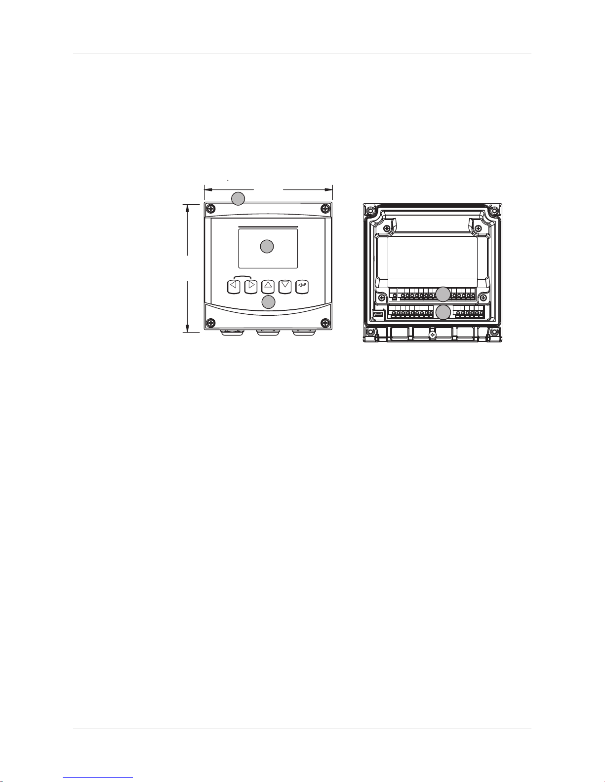
3.1 Overview 1/2DIN
5.90
[150]
5.90
[150]
EnterInfo
CalMenu
M300
1
2
3
ESC
2
1
1: Hard Polycarbonate case 1: TB1 – Input and Output Analog Signal
2: Five Tactile-Feedback Navigation Keys 2: TB2 – Sensor Signal
3: Four-line LCD Display
Page 13
Transmitter M400/2(X)H, M400G/2XH 13
© 12 / 2011 Mettler-Toledo AG, CH-8606 Greifensee, Switzerland Transmitter M400/2(X)H, M400G/2XH
Printed in Switzerland 30 031 683
3.2 Control / Navigation Keys
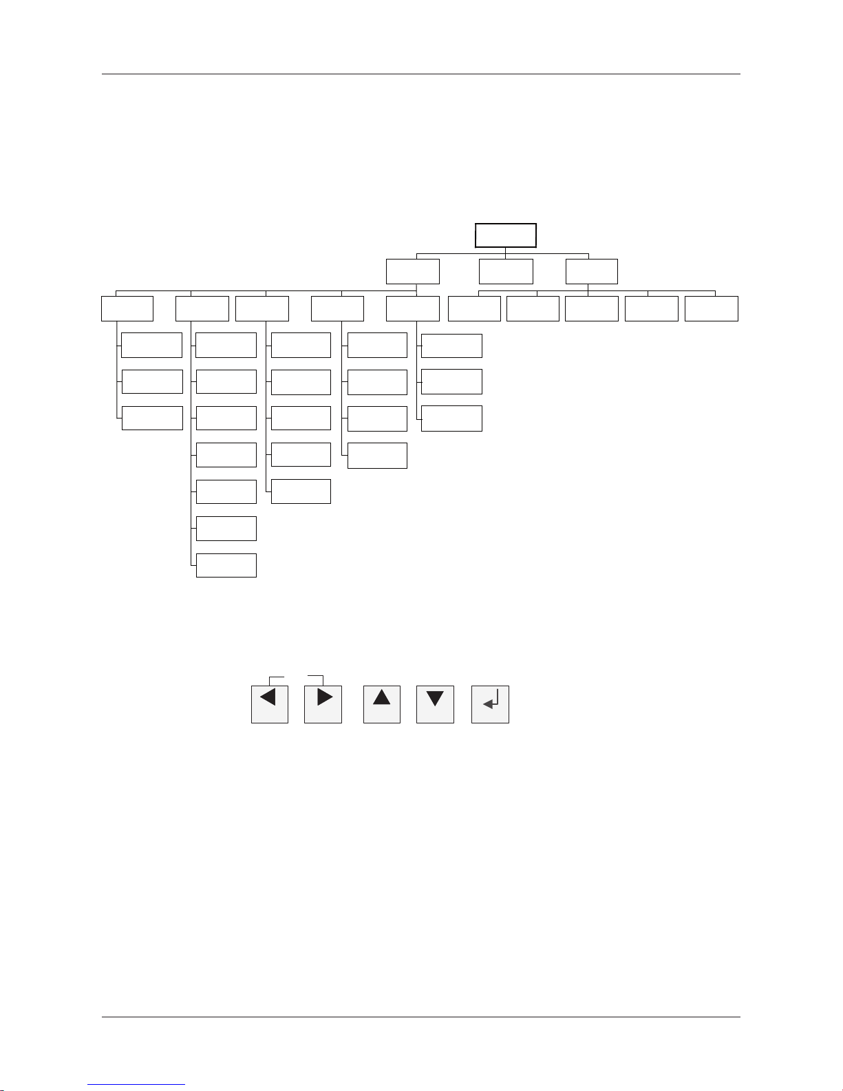
3.2.1 Menu Structure
Below is the structure of the M400 menu tree:
Measurement
Mode M400
CalMenu Info
Quick Setup Configure System PID Setup Service Messages
ISM Sensor
Info*
Measurement
Analog Outputs
Set Points
Alarm/Clean
ISM Setup*
Set Language
Passwords
Set/Clear Lockout
Reset
PID A/M
Tune Parameters
Mode
Calibrate
Tech Service
Diagnostics
Display
Hold Outputs
Set Date & Time
Channel Select
Output
Set Points
Model/Software
Revision
PID Display Setup
Calibration Data
ISM
Diagnostics*
* Only available in combination with ISM sensors
3.2.2 Navigation keys
Menu Cal
Info
Enter
ESC
3.2.2.1 Navigating the menu tree
Enter the desired main Menu branch with the c or keys. Use the and . keys to navigate through the selected Menu branch.
h
NOTE: In order to back up one menu page, without escaping to the measurement mode,
movethe cursor under the UP Arrow character (u) at the bottom right of the display
screenandpress [ENTER].
Page 14

Transmitter M400/2(X)H, M400G/2XH 14
© 12 / 2011 Mettler-Toledo AG, CH-8606 Greifensee, Switzerland Transmitter M400/2(X)H, M400G/2XH
Printed in Switzerland 30 031 683
3.2.2.2 Escape
Press the and c key simultaneously (escape) to return to the Measurement mode.
3.2.2.3 ENTER
Use the e key to confirm action or selections.
3.2.2.4 Menu
Press the key to access the main Menu.
3.2.2.5 Calibration mode
Press the c key to enter Calibration mode.
3.2.2.6 Info mode
Press the . key to enter Info mode.
3.2.3 Navigation of data entry elds
Use the c key to navigate forward or the key to navigate backwards within the changeable
data entry fields of the display.
3.2.4 Entry of data values, selection of data entry options
Use the key to increase or the . key to decrease a digit. Use the same keys to navigate
within a selection of values or options of a data entry field.
h
NOTE: Some screens require configuring multiple values via the same data field (ex: configuring
multiple setpoints). Be sure to use the c or key to return to the primary field and the or
. key to toggle between all configuration options before entering to the next display screen.
Page 15

Transmitter M400/2(X)H, M400G/2XH 15
© 12 / 2011 Mettler-Toledo AG, CH-8606 Greifensee, Switzerland Transmitter M400/2(X)H, M400G/2XH
Printed in Switzerland 30 031 683
3.2.5 Navigation with u in Display
If a u is displayed on the bottom right hand corner of the display, you can use the c or the
key to navigate to it. If you click [ENTER] you will navigate backwards through the menu (go
back one screen). This can be a very useful option to move back up the menu tree without having to exit into the measuring mode and re-enter the menu.
3.2.6 ”Save changes” dialog
Three options are possible for the ”Save changes” dialog: Yes & Exit (Save changes and exit to
measuring mode), ”Yes & u” (Save changes and go back one screen) and ”No & Exit” (Don’t
save changes and exit to measuring mode). The ”Yes & u” option is very useful if you want to
continue configuring without having to re-enter the menu.
3.2.7 Security Passwords
The M400 transmitter allows a security lock-out of various menus. If the security lock-out feature
of the transmitter has been enabled, a security password must be entered to allow access to the
menu. See section 9.3 for more information.
3.2.8 Display
h
NOTE: In the event of an alarm or other error condition the M400 Transmitter will display a flash-
ing a a in the upper right corner of the display. This symbol will remain until the condition that
caused it has been cleared.
h
NOTE: During calibrations (Channel A), clean, Digital In with Analog Output / OC, a flashing ”H”
(Hold) will appear in the upper left corner of the display. During calibration on Channel B, a
flashing ”H” (Hold) will appear in the second line. Change to B and flash. This symbol will
remain for 20 sec., after end of calibration. This symbol will remain for 20 seconds until after
the calibration or clean is completed. This symbol will also disappear when Digital In is
deactivated.
h
NOTE: Channel A (A is shown on the left side of the display) indicates that a conventional
sensor is connected to the transmitter.
Channel B (B is shown on the left side of the display) indicates, that an ISM Sensor is connected
to the transmitter.
The M400 is a single input channel transmitter, and only one sensor can be connected at the
same time.
Page 16

Transmitter M400/2(X)H, M400G/2XH 16
© 12 / 2011 Mettler-Toledo AG, CH-8606 Greifensee, Switzerland Transmitter M400/2(X)H, M400G/2XH
Printed in Switzerland 30 031 683
4 Installation instruction
4.1 Unpacking and inspection of equipment
Inspect the shipping container. If it is damaged, contact the shipper immediately for instructions.
Do not discard the box.
If there is no apparent damage, unpack the container. Be sure all items shown on the packing
list are present.
If items are missing, notify Mettler-Toledo immediately.
4.1.1 Panel cutout dimensional information –
1/2DIN models
1/2DIN Model transmitters are designed with an integral rear cover for stand-alone wall mount
installation.
The unit may also be wall mounted using the integral rear cover. See installation instructions in
Section 4.1.2.
Below are cut-out dimensions required by the 1/2DIN models when mounted within a flat panel
or on a flat enclosure door. This surface must be flat and smooth. Textured or rough surfaces are
not recommended and may limit the effectiveness of the gasket seal provided.
5.39
+0.02
–0.00
[137
+0.5
]
–0.0
5.39
+0.02
–0.00
[137
+0.5
]
–0.0
PANEL CUT-OUT
Optional hardware accessories are available that allow for panel- or pipe-mount.
Refer to Section 15 for ordering information.
Page 17
Transmitter M400/2(X)H, M400G/2XH 17
© 12 / 2011 Mettler-Toledo AG, CH-8606 Greifensee, Switzerland Transmitter M400/2(X)H, M400G/2XH
Printed in Switzerland 30 031 683
4.1.2 Installation procedure
General:
– Orient the transmitter so that the cable grips face downward.
– Wiring routed through the cable grips shall be suitable for use in wet locations.
– In order provide IP66 enclosure ratings, all cable glands must be in place. Each cable gland
must be filled using a cable, or suitable Cable Gland Hole Seal.
For Wall Mount:
– Remove rear cover from front housing.
– Start by unscrewing the four screws located on the face of the transmitter, in each corner. This
allows the front cover to swing away from the rear housing.
– Remove the hinge-pin by squeezing the pin from each end. This allows the front housing to
be removed from the rear housing
– Mount rear housing to wall. Secure mounting kit to the M400 according to the supplied
instructions. Attach to wall using appropriate mounting hardware for wall surface. Be sure it
is level and securely fastened and the installation adheres to any and all clearance dimen-
sions required for transmitter service and maintenance. Orient the transmitter so that the
cable grips are facing downward.
– Replace the front housing to the rear housing. Securely tighten the rear-cover screws to
ensure that IP66/NEMA4X enclosure environmental rating is maintained. The unit is ready to
be wired.
For Pipe Mount:
– Use only manufacturer-supplied components for pipe-mounting the M400 transmitter and
install per the supplied instructions. See section 15 for ordering information.
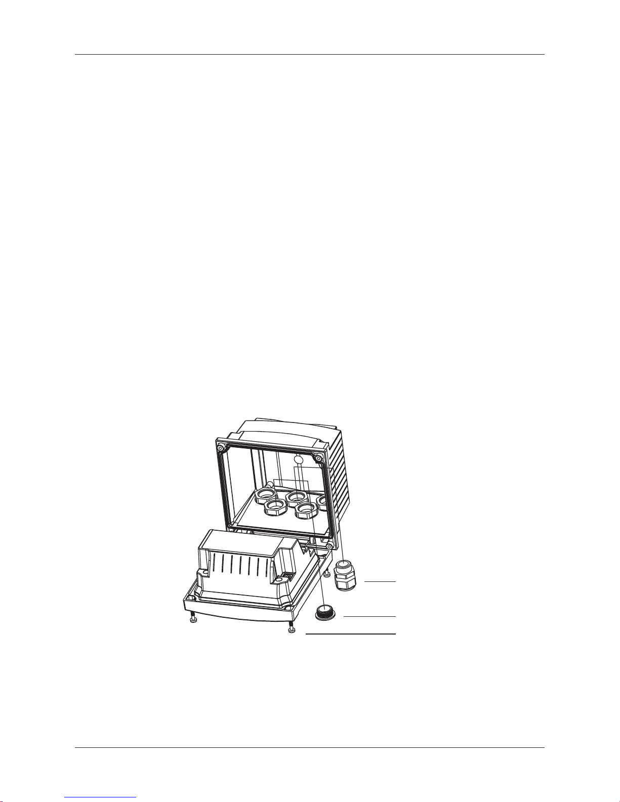
4.1.3 Assembly – 1/2DIN version
1
2
3
1. 3 M20X1.5 cable glands
2. Plastics plugs
3. 4 screws
Page 18
Transmitter M400/2(X)H, M400G/2XH 18
© 12 / 2011 Mettler-Toledo AG, CH-8606 Greifensee, Switzerland Transmitter M400/2(X)H, M400G/2XH
Printed in Switzerland 30 031 683
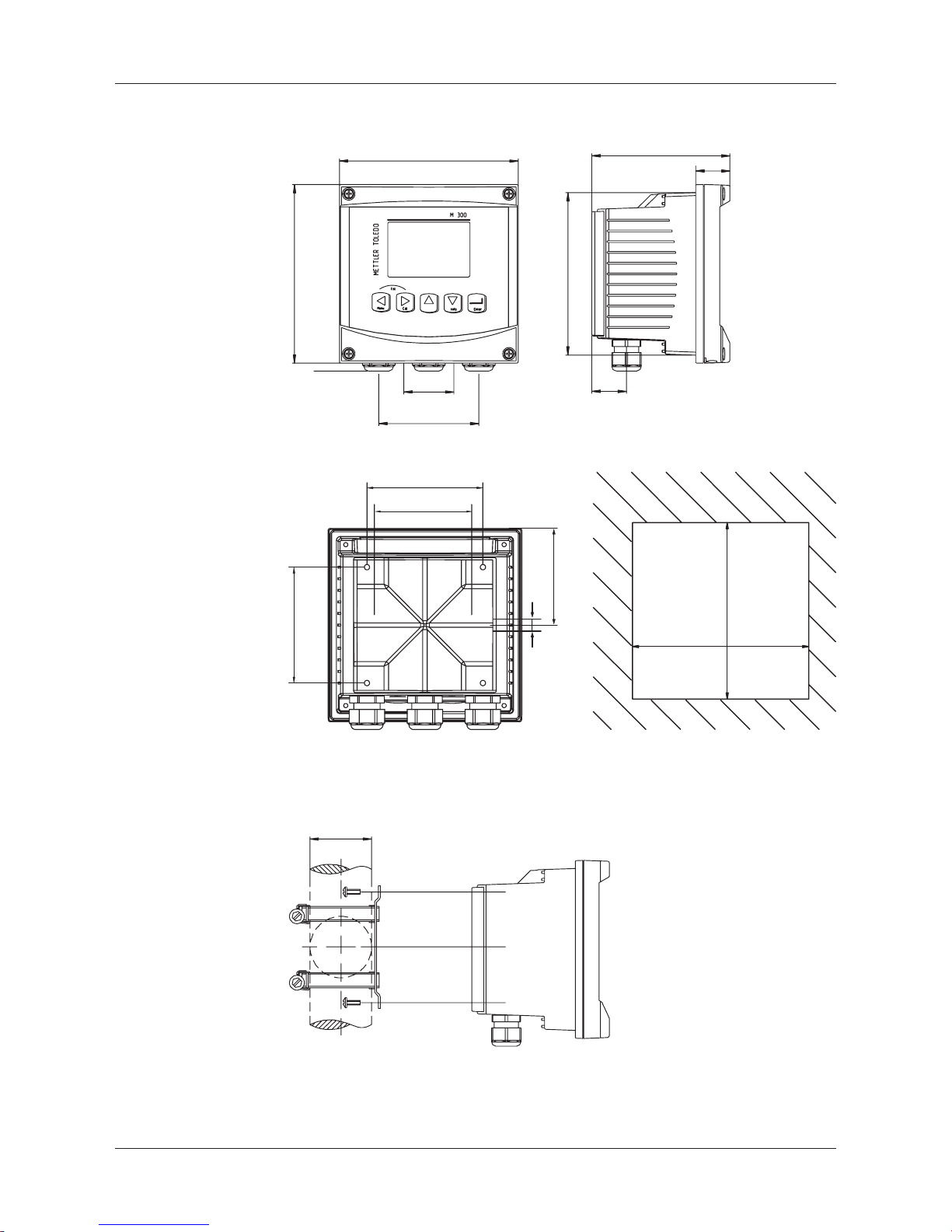
4.1.4 1/2DIN version – Dimension drawings
90 mm
3.54"
43 mm
1.69"
136 mm / 5.35"
150 mm / 5.9"
114 mm / 4.49"
150 mm / 5.9"
28 mm
1.10"
27 mm
1.06"
90 mm / 3.54"
90 mm / 3.54"
75 mm / 2.95"
35mm/
1.38”
6 mm/
0.236”
80 mm / 3.15"
5.39” 0.02”
+
-
5.39” 0.02”
+
-
137mm 0.5mm
+
-
137mm 0.5mm
+
-
4.1.5 1/2DIN version – Pipe mounting
40 ... 60 mm
1.57... 2.36"
Page 19

Transmitter M400/2(X)H, M400G/2XH 19
© 12 / 2011 Mettler-Toledo AG, CH-8606 Greifensee, Switzerland Transmitter M400/2(X)H, M400G/2XH
Printed in Switzerland 30 031 683
4.2 Connection of power supply
All connections to the transmitter are made on the rear panel of all models.
a
Be sure power to all wires is turned off before proceeding with the installation.
A two-terminal connector on the rear panel of all M400 models is provided for power connection. All M400 models are designed to operate from a 14–30 VDC power source. Refer to
specifications for power requirements and ratings and size power wiring accordingly (AWG 16 –
24, wire cross-section 0.2 mm2 to 1.5 mm2).
The terminal block for power connections is labeled ”Power” on the rear panel of the transmitter.
One terminal is labeled – N for the Neutral wire and the other + L for the Line (or Load) wire.
The terminals are suitable for single wires and flexible leads 0.2 mm2 to 2.5 mm2 (AWG 16 –
24). There is no earth ground terminal on the transmitter. For this reason the internal power wiring within the transmitter is double insulated and the product label designates this using the d
symbol.
4.2.1 Housing (wall mount)
2
1
1: TB1 – Input and Output Analog Signal
2: TB2 – Sensor Signal
Page 20
Transmitter M400/2(X)H, M400G/2XH 20
© 12 / 2011 Mettler-Toledo AG, CH-8606 Greifensee, Switzerland Transmitter M400/2(X)H, M400G/2XH
Printed in Switzerland 30 031 683
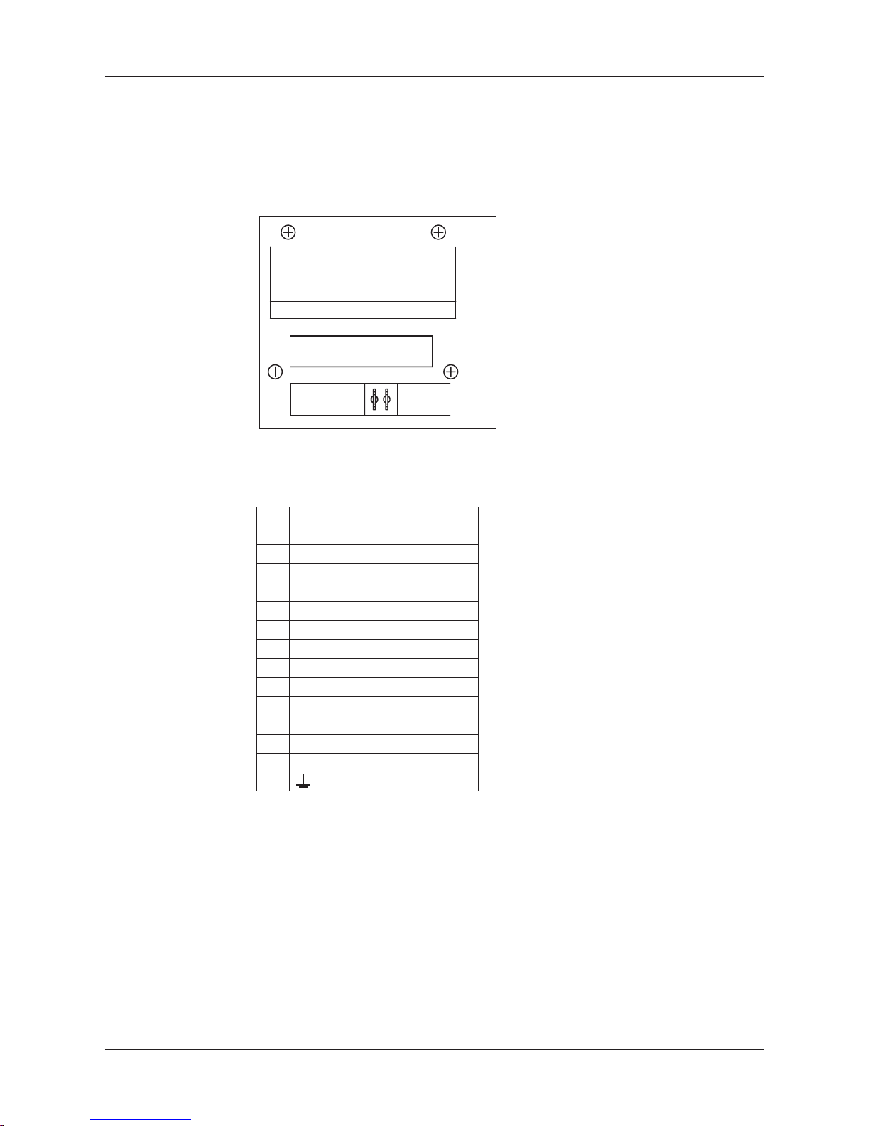
4.3 Connector PIN denition
4.3.1 Terminal Block (TB) Denitions
Power connections are labeled
– N for Neutral and + L for Line, for 14–30 VDC.
TB1
TB2
A Q
1 9 10 15
Power connections are labeled A01+ / HART and A01– / HART
resp. A02+ and A02– for 14 to 30 VDC.
TB1
1 DI1+
2 DI1–
3 DI2+
4 DI2–
5 Not used
6 OC1+
7 OC1–
8 OC2+
9 OC2–
10 AO1+/HART
11 AO1–/HART
12 AO2+
13 AO2–
14 Not used
15
OC1, 2 =
Open collector output 1, 2.
Page 21
Transmitter M400/2(X)H, M400G/2XH 21
© 12 / 2011 Mettler-Toledo AG, CH-8606 Greifensee, Switzerland Transmitter M400/2(X)H, M400G/2XH
Printed in Switzerland 30 031 683
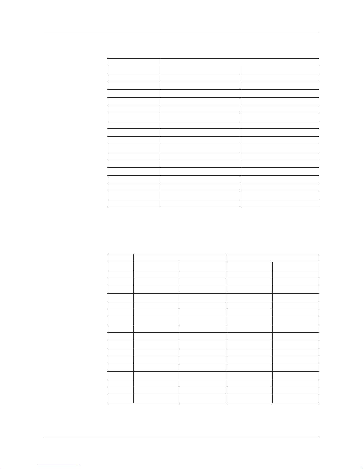
4.3.2 TB2 Conductivity 4-E/2-E Analog Sensors
TB2 – Analog Sensors
Cond 4-E or 2-E
Terminal Function Color
A Cnd inner1* white
B Cnd outer1* white/blue
C Cnd outer1 –
D Not used –
E Cnd outer2 –
F Cnd inner2** blue
G Cnd outer2 (GND)** black
H Not used –
I RTD ret/GND bare shield
J RTD sense red
K RTD green
L Not used –
M Not used –
N Not used –
O Not used –
P Not used –
Q Not used –
* For third party Cond 2-E sensors may be jumper between A and B has to be installed.
** For third party Cond 2-E sensors may be jumper between F and G has to be installed.
4.3.3 Analog Sensors
TB2 – Analog Sensors
pH Redox (ORP)
Terminal Function Color* Function Color
A Glass transparent Platinum transparent
B Not used – – –
C No used – – –
D Not used – – –
E Reference red Reference red
F Reference** – Reference** –
G Solution GND** blue*** Solution GND** –
H Not used – – –
I RTD ret/GND white – –
J RTD sense – – –
K RTD green – –
L Not used – – –
M Shield (GND) green/yellow Shield (GND) green/yellow
N Not used – – –
O Not used – – –
P Not used – – –
Q Not used – – –
* Grey wire not used.
** Install jumper between F and G for ORP sensors and pH electrodes without SG.
*** Blue wire for electrode with SG.
Page 22
Transmitter M400/2(X)H, M400G/2XH 22
© 12 / 2011 Mettler-Toledo AG, CH-8606 Greifensee, Switzerland Transmitter M400/2(X)H, M400G/2XH
Printed in Switzerland 30 031 683
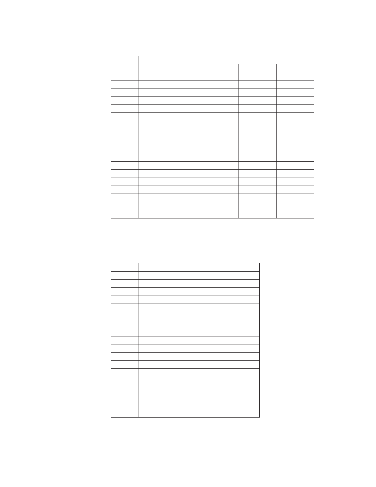
4.3.4 TB2 Analog Oxygen Sensors
InPro6800(G) InPro6900 InPro6950
Terminal Function Color Color Color
A Not used – – –
B Anode red red red
C Anode –* –* –
D Reference –* –* blue
E Not used – – –
F Not used – – –
G Guard – grey grey
H Cathode transparent transparent transparent
I NTC ret (GND) white white white
J Not used – – –
K NTC green green green
L Not used – – –
M Shield (GND) green/yellow green/yellow green/yellow
N Not used – – –
O Not used – – –
P + input 4/20 mA signal – – –
Q – input 4/20 mA signal – – –
* Install jumber between C and D for InPro6800(G) and InPro6900
4.3.5 TB2 – ISM (Digital) Sensors
pH, amp. Oxygen, Cond 4-e
Terminal Function Color
A Not used –
B Not used –
C Not used –
D Not used –
E Not used –
F Not used –
G Not used –
H Not used –
I Not used –
J Not used –
K Not used –
L 1-wire transparent (cable core)
M GND red (shield)
N Not used –
O Not used –
P Not used –
Q Not used –
Page 23
Transmitter M400/2(X)H, M400G/2XH 23
© 12 / 2011 Mettler-Toledo AG, CH-8606 Greifensee, Switzerland Transmitter M400/2(X)H, M400G/2XH
Printed in Switzerland 30 031 683
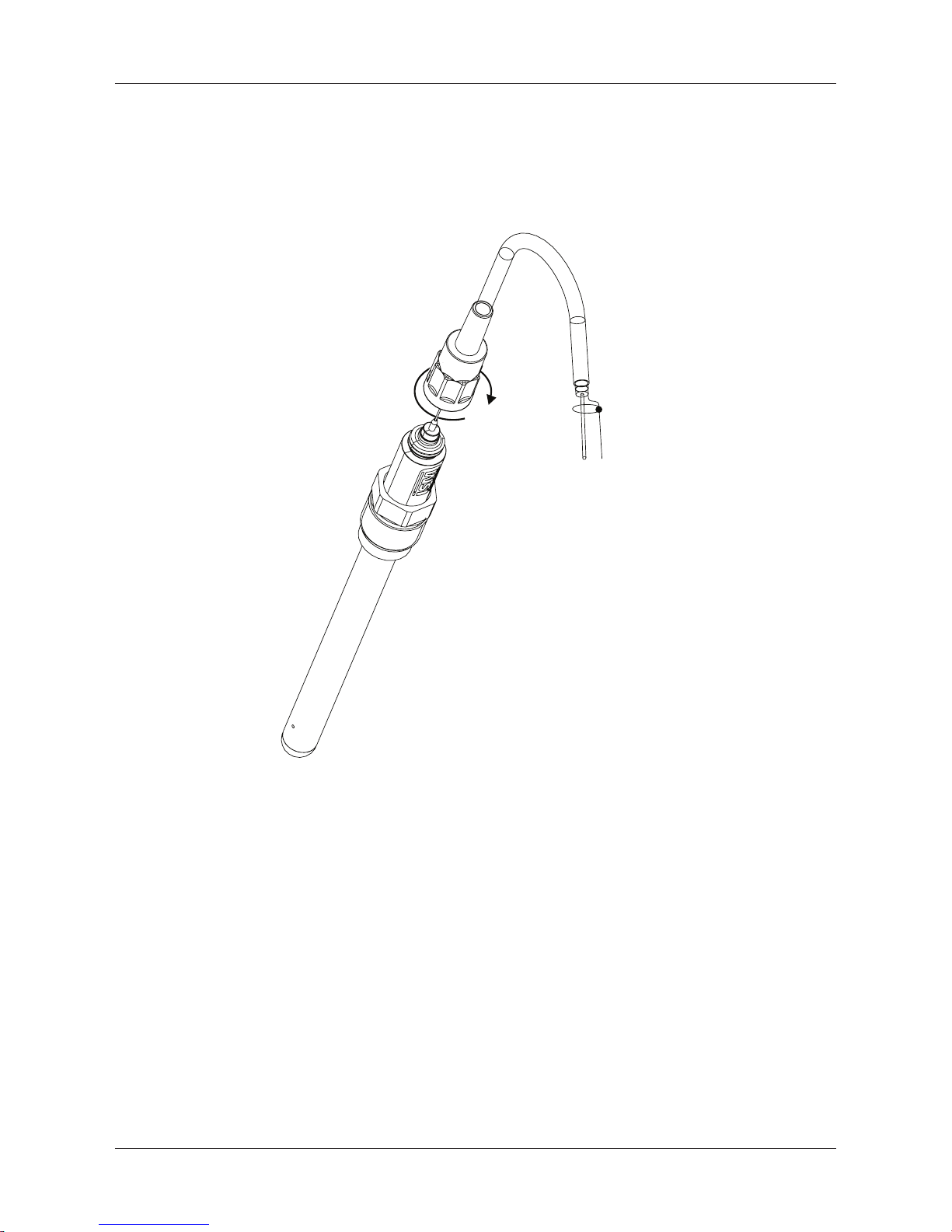
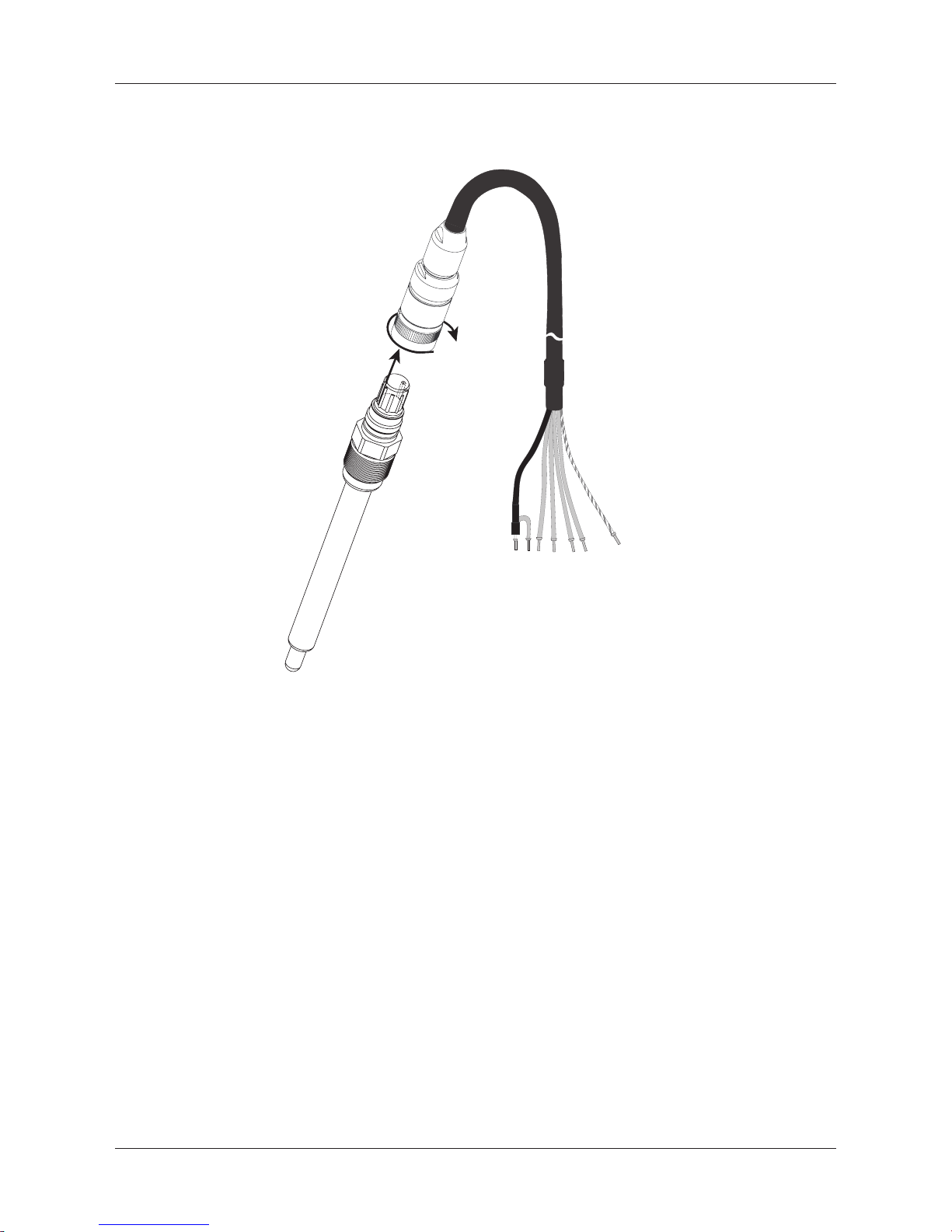
4.4 Connection of ISM (digital) sensors
4.4.1 Connection of ISM sensors for pH/ORP,
Cond 4-e and amperometric oxygen measurement
*
**
h
NOTE: Connect the sensor and screw the plug head clockwise (hand tight).
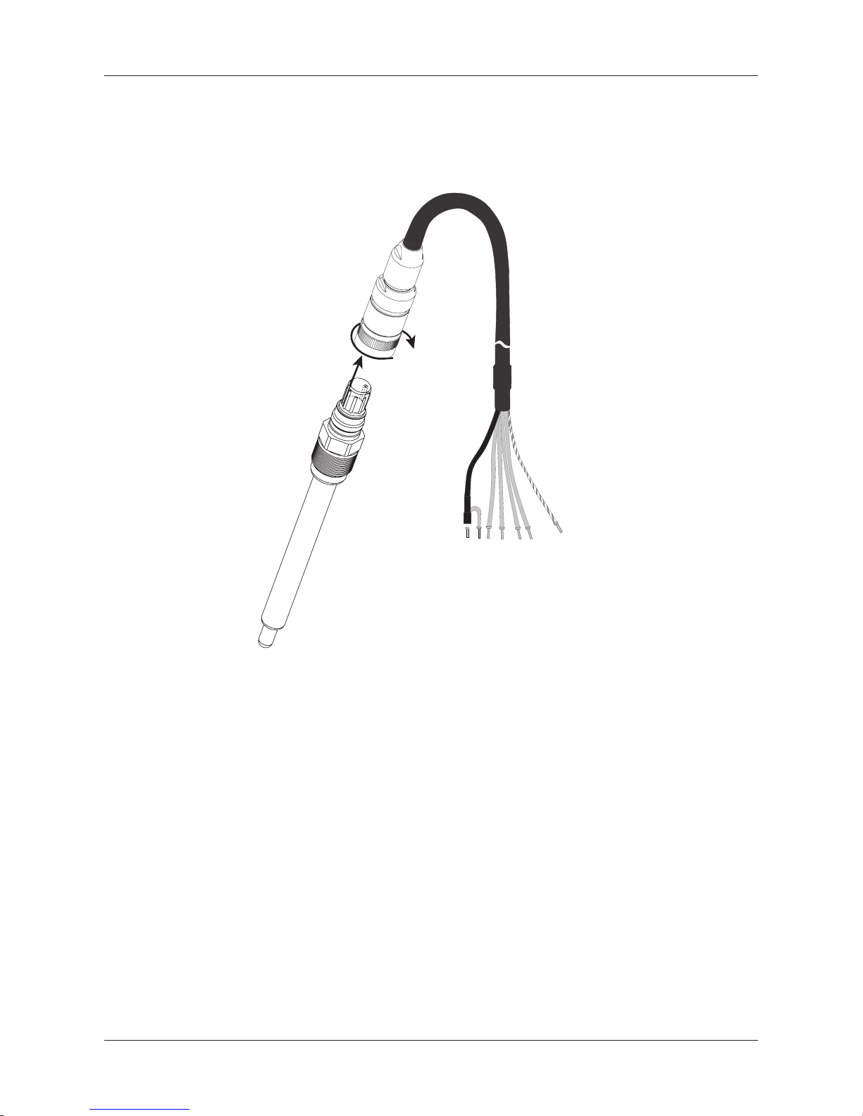
4.4.2 TB2 – AK9 cable assignment
* 1-wire data (transparent)
** Ground/shield
Page 24
Transmitter M400/2(X)H, M400G/2XH 24
© 12 / 2011 Mettler-Toledo AG, CH-8606 Greifensee, Switzerland Transmitter M400/2(X)H, M400G/2XH
Printed in Switzerland 30 031 683
4.5 Connection of analog sensors
4.5.1 Connection of analog sensor for pH / ORP
h
NOTE: Cable lengths > 20 m can worsen the response during pH measurement. Be sure to
observe the sensor instruction manual.
Page 25
Transmitter M400/2(X)H, M400G/2XH 25
© 12 / 2011 Mettler-Toledo AG, CH-8606 Greifensee, Switzerland Transmitter M400/2(X)H, M400G/2XH
Printed in Switzerland 30 031 683
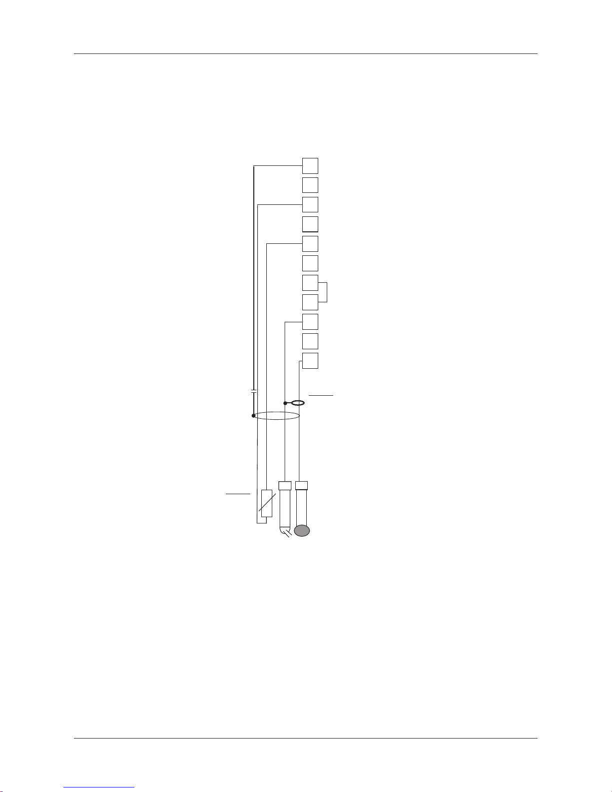
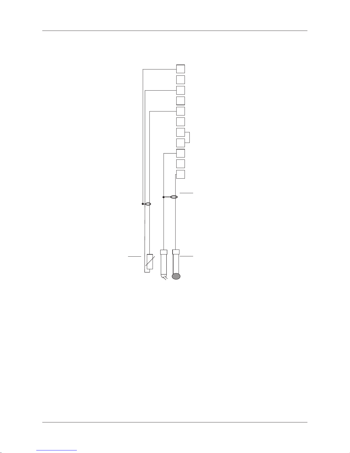
4.5.2 TB2 – Typical wiring for analog pH/ORP sensor
4.5.2.1 Example 1
pH measurement without Solution Ground
A
B
E
F
G
H
I
J
K
yellowgreen
green
red
transparent
white
Combination
pH electrode
Temperature
probe
Cable
Jumper
L
M
h
NOTE: Jumber terminals G and F
Wire Colors only valid for connection with VP caple; blue and grey not connected.
A: Glass
E: Reference
I: RTD ret/GND
K: RTD
M: Shield/GND
Page 26
Transmitter M400/2(X)H, M400G/2XH 26
© 12 / 2011 Mettler-Toledo AG, CH-8606 Greifensee, Switzerland Transmitter M400/2(X)H, M400G/2XH
Printed in Switzerland 30 031 683
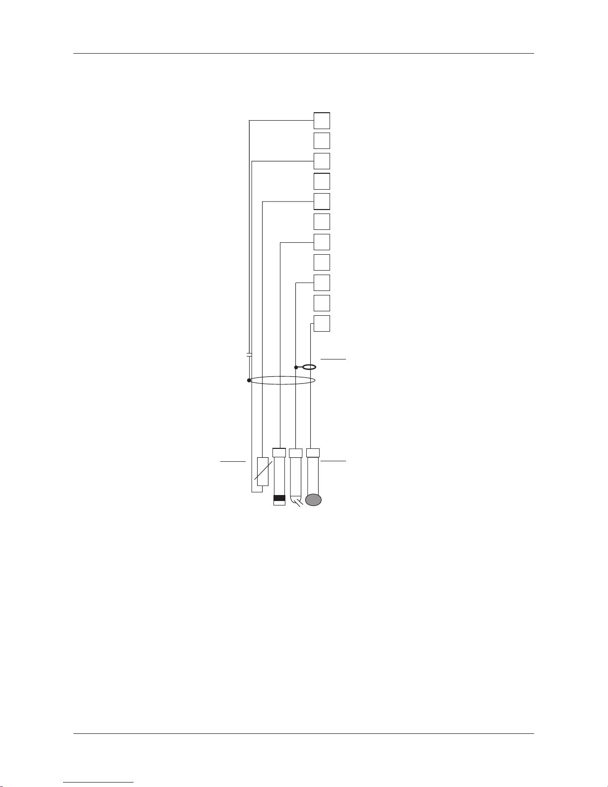
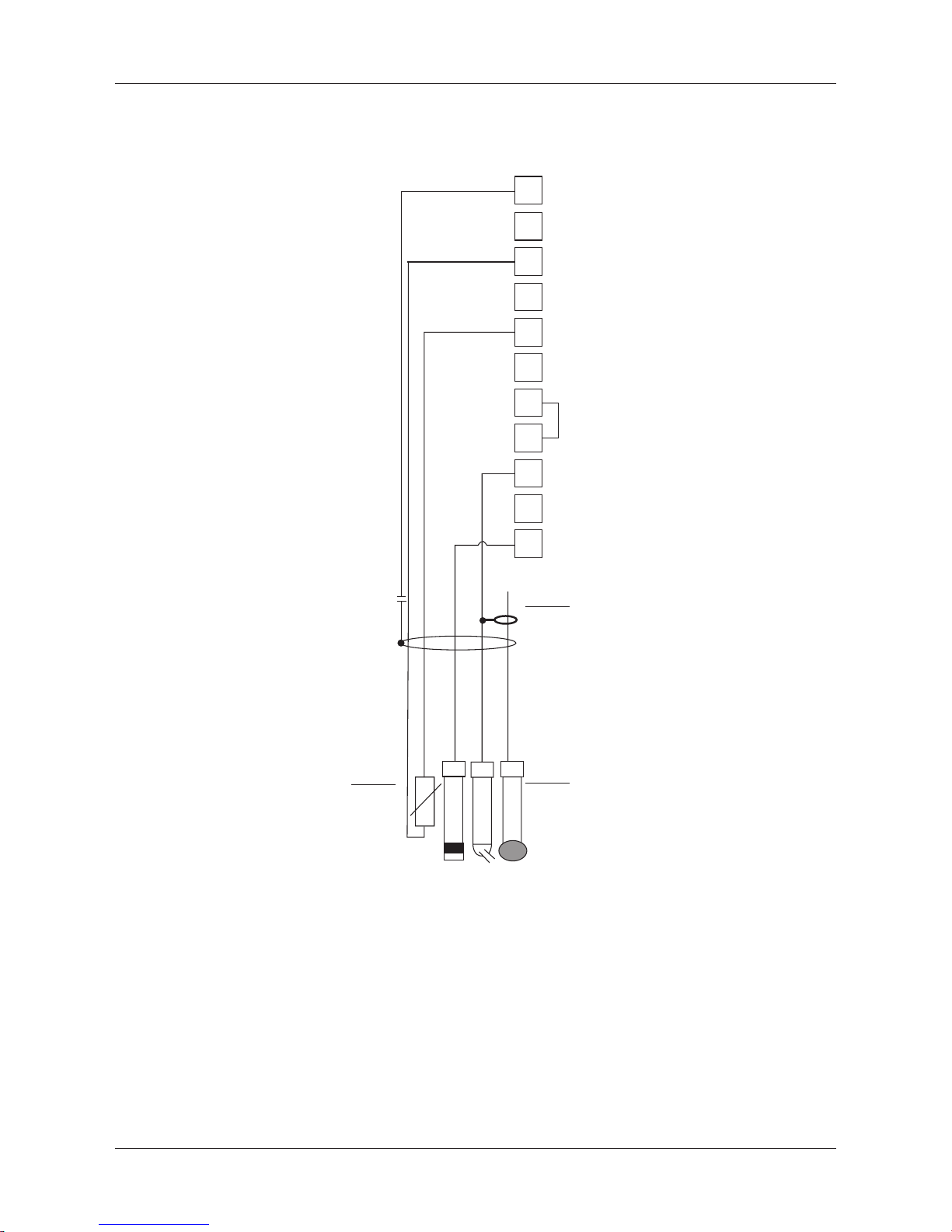
4.5.2.2 Example 2
pH measurement with Solution Ground
A
B
E
F
G
H
I
J
K
yellowgreen
green
red
transparent
white
Combination
pH electrode
with RTD
and SG
Temperature
probe
blue
Cable
L
M
h
NOTE: Wire colors only valid for connection with VP cable, grey not connected.
A: Glass
E: Reference
G: Shield/Solution GND
I: GND/RTD ret
K: RTD
M: Shield(GND)
Page 27
Transmitter M400/2(X)H, M400G/2XH 27
© 12 / 2011 Mettler-Toledo AG, CH-8606 Greifensee, Switzerland Transmitter M400/2(X)H, M400G/2XH
Printed in Switzerland 30 031 683
4.5.2.3 Example 3
ORP (redox) measurement (temperature optional)
A
B
E
F
G
H
I
J
K
ORP electrode
Temperature
Reference electrode
Sensing electrode
probe
Cable
Jumper
L
M
h
NOTE: Jumper terminal G and F
A: Platinum
E: Reference
I: RTD ret/GND
K: RTD
M: Shield(GND)
Page 28
Transmitter M400/2(X)H, M400G/2XH 28
© 12 / 2011 Mettler-Toledo AG, CH-8606 Greifensee, Switzerland Transmitter M400/2(X)H, M400G/2XH
Printed in Switzerland 30 031 683
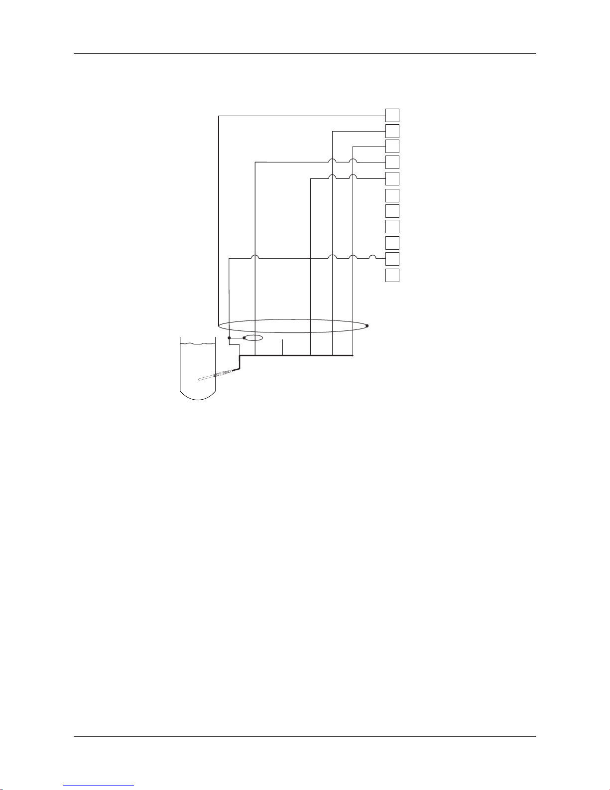
4.5.2.4 Example 4
ORP measurement with pH solution ground electrode (e.g. InPro 3250, InPro 4800 SG).
A
B
E
F
G
H
I
J
K
yellowgreen
green
red
transparent
white
Combination
pH electrode
with RTD
and SG
Temperature
probe
blue
Cable
Not connected
Jumper
L
M
h
NOTE: Jumper terminal G and F
A: Platinum
E: Reference
I: RTD ret/GND
K: RTD
M: Shiled(GND)
Page 29
Transmitter M400/2(X)H, M400G/2XH 29
© 12 / 2011 Mettler-Toledo AG, CH-8606 Greifensee, Switzerland Transmitter M400/2(X)H, M400G/2XH
Printed in Switzerland 30 031 683
4.5.3 Connection of analog sensor for amperometric
oxygen measurement
h
NOTE: Be sure to observe the sensor instruction manual.
Page 30
Transmitter M400/2(X)H, M400G/2XH 30
© 12 / 2011 Mettler-Toledo AG, CH-8606 Greifensee, Switzerland Transmitter M400/2(X)H, M400G/2XH
Printed in Switzerland 30 031 683
4.5.4 TB2 – Typical wiring for analog sensor for
Amperometric oxygen measurement
red
transparent
yellow/green
gr
een
white
grey
blue
A
B
C
D
E
F
G
H
I
K
M
h
NOTE: Wire colors only valid for connection with VP cable, but not connected.
M400 connector:
B: Anode
G: Reference
H: Cathode
I: NTC ret/Guard
K: NTC
M: Shield (GND)
Page 31

Transmitter M400/2(X)H, M400G/2XH 31
© 12 / 2011 Mettler-Toledo AG, CH-8606 Greifensee, Switzerland Transmitter M400/2(X)H, M400G/2XH
Printed in Switzerland 30 031 683
5 Placing transmitter in, or out, of service
5.1 Placing transmitter in service
a
After connecting the transmitter to power supply circuit, it will be active as soon as the circuit is
powered.
5.2 Placing transmitter out of service
First disconnect the unit from the main power source, then disconnect all remaining electrical
connections. Remove the unit from the wall / panel. Use the installation instruction in this manual
as reference for dis-assembling mounting hardware.
All transmitter settings stored in memory are non volatile.
Page 32

Transmitter M400/2(X)H, M400G/2XH 32
© 12 / 2011 Mettler-Toledo AG, CH-8606 Greifensee, Switzerland Transmitter M400/2(X)H, M400G/2XH
Printed in Switzerland 30 031 683
6 Quick Setup
(PATH: Menu / Quick Setup)
Select Quick Setup and press the [ENTER] key. Enter the security code if necessary
(see section9.2 “Passwords”)
h
NOTE: Please find the complete description of the Quick Setup routine described in the separate
booklet “Quick Setup Guide for Transmitter M400” enclosed in the box.
h
NOTE: Please do not use Quick Setup menu after configuration of the transmitter, because some
of the parameters i.e. analog output configuration will may be reseted.
h
NOTE: Refer to section 3.2 “Control/Navigation Keys” for information on menu navigation.
Page 33

Transmitter M400/2(X)H, M400G/2XH 33
© 12 / 2011 Mettler-Toledo AG, CH-8606 Greifensee, Switzerland Transmitter M400/2(X)H, M400G/2XH
Printed in Switzerland 30 031 683
7 Sensor Calibration
(PATH: Cal)
The calibration key c allows the user one-touch access to sensor calibration and verification
features.
h
NOTE: During Calibration on Channel A, a flashing ”H” (Hold) in the upper left corner of the
Display indicates a calibration is in process with a Hold condition active. (The hold output
needs to be activated.) See also chapter 3.2.8 “Display”.
7.1 Enter Calibration Mode
While in Measurement mode press the c key. If the display prompts you to enter the Calibration
security code, press the or . key to set the calibration security mode, the [ENTER] key to
confirm the calibration security code.
Press the or . key to select the type of calibration desired.
Select the desired sensor Calibration task. The choices for each sensor type are:
Conductivity = Conductivity, Resistivity, Temperature**, Edit**, Verify
Oxygen = Oxygen, Temperature**, Edit**, Verify
pH = pH, mV**, Temperature**, Edit pH**, Edit mV**, Verify, ORP***
Press [ENTER].
** only on channel ”A”
*** only available on channel ”B”
After every successful calibration, the three options are available:
Adjust: Calibration values will be overtaken und used for the measurement. Additionally, the
data will be stored in the calibration history*.
Calibrate: Calibration values will be stored in the calibration history* for documentation, but will
not be used for the measurement. The calibration values from the last valid adjustment will be further used for the measurement.
Abort: Calibration values will be discarded.
* only available with ISM sensors
Page 34

Transmitter M400/2(X)H, M400G/2XH 34
© 12 / 2011 Mettler-Toledo AG, CH-8606 Greifensee, Switzerland Transmitter M400/2(X)H, M400G/2XH
Printed in Switzerland 30 031 683
7.2 Conductivity calibration
for two- or four-electrode sensors
This feature provides the ability to perform a one-point, two-point or process Conductivity resp.
Resistivity “Sensor” calibration for two- or four-electrode sensors. The procedure described below
works for both types of calibrations. There is no reason to perform a two-point calibration on a
two-electrode conductivity sensor.
h
NOTE: When performing calibration on a conductivity sensor, results will vary depending on the
methods, calibration apparatus and/or quality of reference standards used to perform the calibration.
h
NOTE: For measuring tasks the temperature compensation for the application as defined at the
menu Resistivity will be considered and not the temperature compensation selected thru the
calibration procedure (see also chapter 8.2.3.1 “Conductivity temperature compensation”;
PATH: Menu/Configure/Measurement/Resistivity).
Enter Conductivity sensor calibration mode as described in section 7.1 “Enter Calibration Mode”.
The next screen will ask to select the type of temperature compensation mode desired during the
calibration process.
Choices are “Standard”, “Lin 25 °C”, “Lin 20 °C” or “Nat H2O” compensation mode.
Standard compensation: includes compensation for non-linear high purity effects as well as
conventional neutral salt impurities and conforms to ASTM standards
D1125 and D5391.
Lin 25°C compensation: adjusts the reading by a factor expressed as “% per °C” deviation
from 25 °C. The factor can be modified.
Lin 20°C compensation: adjusts the reading by a factor expressed as “% per °C” deviation
from 20 °C. The factor can be modified.
Nat H2O compensation: includes compensation to 25 °C according to EN27888 for natural
water.
Choose the compensation mode, modify the factor where appropriate and press [ENTER].
7.2.1 One-point sensor calibration
(Display reflects typical Conductivity Sensor calibration)
Enter Conductivity Sensor Calibration mode as described in section 7.1 “Enter Calibration Mode”
and choose one of the compensation modes (see section 7.2 “Conductivity calibration for two
or four electrode sensors”).
Select 1 point calibration and press [ENTER]. With conductivity sensors a one-point calibration
is always performed as a slope calibration.
Place the electrode into the reference solution.
Page 35

Transmitter M400/2(X)H, M400G/2XH 35
© 12 / 2011 Mettler-Toledo AG, CH-8606 Greifensee, Switzerland Transmitter M400/2(X)H, M400G/2XH
Printed in Switzerland 30 031 683
Enter the value for Point 1 including a decimal point and units. The value in the second text line
is the value being measured by the transmitter and sensor in the units selected by the user.
Press [ENTER] when this value is stable to perform the calibration.
After the calibration the cell multiplier or slope calibration factor ”M” i.e. cell constant and the
Adder or offset calibration factor ”A” are displayed.
In case of a successful calibration, the calibration values are stored in the cal history* and taken
over (Adjust), stored in the cal history* and not taken over (Calibrate) or discarded (Abort).
* only available with ISM sensor. The values will be stored in the sensor.
If ”Adjust” or ”Calibrate” are chosen, the message ”Calibration successful” is displayed. In any
case you will get the message ”Re-install sensor” and ”Press ENTER” on the display. After pressing ”ENTER” the M400 returns to the measuring mode.
7.2.2 Two-point sensor calibration
(four electrode sensors only)
(Display reflects typical Conductivity sensor calibration)
Enter Conductivity Sensor Calibration mode as described in section 7.1 “Enter Calibration Mode”
and choose one of the compensation modes (see section 7.2 “Conductivity calibration for two
or four electrode sensors”).
Select 2 point calibration and press [ENTER].
Place the electrode into the first reference solution.
CAUTION: Rinse sensors with a high-purity water solution between calibration points to prevent
contamination of the reference solutions.
Enter the value for Point 1 including a decimal point and units. The value in the second text line
is the value being measured by the transmitter and sensor in the units selected by the user.
Press [ENTER] when this value is stable and place the electrode into the second reference
solution.
Enter the value for Point 2 including a decimal point and units. The value in the second text line
is the value being measured by the transmitter and sensor in the units selected by the user.
Press [ENTER] when this value is stable to perform the calibration.
After the calibration of the cell multiplier or slope calibration factor ”M” i.e. cell constant and the
adder or offset calibration factor ”A” are displayed.
In case of a successful calibration, the calibration values are stored in the cal history* and taken
over (Adjust), stored in the cal history* and not taken over (Calibrate) or discarded (Abort).
* only available with ISM sensor. The values will be stored in the sensor.
If ”Adjust” or ”Calibrate” are chosen, the message ”Calibration successful” is displayed. In any
case you will get the message ”Re-install sensor” and ”Press ENTER” on the display. After pressing ”ENTER” the M400 returns to the measuring mode.
Page 36

Transmitter M400/2(X)H, M400G/2XH 36
© 12 / 2011 Mettler-Toledo AG, CH-8606 Greifensee, Switzerland Transmitter M400/2(X)H, M400G/2XH
Printed in Switzerland 30 031 683
7.2.3 Process Calibration
(Display reflects typical Conductivity sensor calibration)
Enter Conductivity Sensor Calibration mode as described in section 7.1 “Enter Calibration Mode”
and choose one of the compensation modes (see section 7.2 “Conductivity calibration for twoor four electrode sensors”).
Select Process Calibration and press [ENTER]. With conductivity sensors a process calibration
is always performed as a slope calibration.
Take a sample and press the [ENTER] key again to store the current measuring value.
During the ongoing calibration process, the letter of the channel, which is concerned by the calibration, “A” or “B” is blinking in the display.
After determining the conductivity value of the sample, press the [CAL] key again to proceed
with the calibration.
Enter the conductivity value of the sample, then press the [ENTER] key to start the calculation of
calibration results.
After the calibration the Multiplier or slope calibration factor “M” and the Adder or offset calibra-
tion factor “A” are displayed.
In case of a successful calibration, the calibration values are stored in the cal history* and taken
over (Adjust), stored in the cal history* and not taken over (Calibrate) or discarded (Abort).
* only available with ISM sensor. The values will be stored in the sensor.
If “Adjust” or “Calibrate” are chosen, the message “Calibration successful” is displayed. The
M400 returns to the measuring mode.
7.3 Calibration of amperometric oxygen sensors
Oxygen calibration for amperometric sensors is performed as either a one-point or process
calibration.
h
NOTE: Before air calibration, for highest accuracy, enter the barometric pressure and relative hu-
midity, as described in section 8.2.3.4 “Parameters for oxygen measurement based on amperometric sensors”.
Page 37

Transmitter M400/2(X)H, M400G/2XH 37
© 12 / 2011 Mettler-Toledo AG, CH-8606 Greifensee, Switzerland Transmitter M400/2(X)H, M400G/2XH
Printed in Switzerland 30 031 683
7.3.1 One-point calibration for amperometric oxygen
sensors
Enter Oxygen calibration mode as described in section 7.1 “Enter Calibration Mode”.
A one-point calibration of oxygen sensors is always either a one point slope (i.e. with air) or a
zero (offset) calibration. A one point slope calibration is done in air and a one point offset calibration is done at 0 ppb oxygen. A one-point zero dissolved oxygen calibration is available but
not normally recommended since zero oxygen is very hard to achieve. A zero-point calibration is
only recommended if high accuracy at low oxygen level (below 5% air) is needed.
Select 1 point followed by either Slope or ZeroPt as the calibration type.
Press [ENTER].
Adjust calibration pressure (CalPres) and relative humidity (RelativeHumid), which are applied
during calibration. Press [ENTER].
Place the sensor in the calibration gas (e.g. air) resp. solution. Press [ENTER].
Depending on the parameterized Drift control (see chapter 8.2.3.4 “Parameters for oxygen measurement based on amperometric sensors”) one of the two following modes is active.
7.3.1.1 Auto mode
h
NOTE: For a zero point calibration the Auto mode is not available. If Auto mode has been config-
ured (see section 8.2.3.4 “Parameters for oxygen measurement based on amperometric sensors”) and an offset calibration will be executed, the transmitter will perform the calibration in
Manual mode.
Enter the value for Point 1 including a decimal point and units. The value in the second text line
is the value being measured by the transmitter and sensor in the units selected by the user.
As soon as the stabilization criteria have been fulfilled the display changes. The display shows
the calibration result for slope “S” and offset value ”Z”.
In case of a successful calibration, the calibration values are stored in the cal history* and taken
over (Adjust), stored in the cal history* and not taken over (Calibrate) or discarded (Abort).
* only available with ISM sensor. The values will be stored in the sensor.
Page 38

Transmitter M400/2(X)H, M400G/2XH 38
© 12 / 2011 Mettler-Toledo AG, CH-8606 Greifensee, Switzerland Transmitter M400/2(X)H, M400G/2XH
Printed in Switzerland 30 031 683
7.3.1.2 Manual mode
Enter the value for Point 1 including a decimal point and units. The value in the second text line
is the value being measured by the transmitter and sensor in the units selected by the user.
Press [ENTER] when this value is stable to perform the calibration.
After the calibration the slope “S” and the offset value ”Z” are displayed.
In case of a successful calibration, the calibration values are stored in the cal history* and taken
over (Adjust), stored in the cal history* and not taken over (Calibrate) or discarded (Abort).
* only available with ISM sensor. The values will be stored in the sensor.
If “Adjust” or “Calibrate” are chosen, the message “Calibration successful” is displayed. In any
case you will get the message “Re-install sensor” and “Press ENTER” on the display. After pressing “ENTER” the M400 returns to the measuring mode.
h
NOTE: With ISM sensors: If a one point calibration is executed, the transmitter sends the polar-
ization voltage, valid for the calibration, to the sensor. If the polarization voltage for the measuring mode and calibration mode is different, the transmitter will wait 120 seconds before starting
the calibration. In this case the transmitter will also go after the calibration for 120 seconds to
the HOLD Mode, before returning to the measuring mode again. (see also chapter8.2.3.4
“Parameter for oxygen measurement based on amperometric sensors”).
7.3.2 Process calibration for amperometric oxygen sensors
Enter Oxygen calibration mode as described in section 7.1 “Enter Calibration Mode”.
A process calibration of oxygen sensors is always either a slope or a offset calibration.
Select Process followed by either Slope or ZeroPt as the calibration type. Press [ENTER]
Take a sample and press the [ENTER] key again to store the current measuring value. To show
the ongoing calibration process, A or B (depending on the channel) is blinking in the display.
After determining the O2 value of the sample press the c key again to proceed with the
calibration.
Enter the O2 value of the sample then press the [ENTER] key to start the calculation of the
calibration results.
Page 39

Transmitter M400/2(X)H, M400G/2XH 39
© 12 / 2011 Mettler-Toledo AG, CH-8606 Greifensee, Switzerland Transmitter M400/2(X)H, M400G/2XH
Printed in Switzerland 30 031 683
After the calibration the slope ”S” and the offset value ”Z” are displayed.
In case of a successful calibration, the calibration values are stored in the cal history* and taken
over (Adjust), stored in the cal history* and not taken over (Calibrate) or discarded (Abort).
* only available with ISM sensor. The values will be stored in the sensor.
If ”Adjust” or ”Calibrate” are chosen, the message ”Calibration successful” is displayed. The
M400 returns to the measuring mode.
7.4 pH calibration
For pH sensors, the M400 transmitter features one-point, two-point (Auto or Manual mode) or
process calibration with 9 preset buffer sets or manual buffer entry. Buffer values refer to 25 °C.
To calibrate the instrument with automatic buffer recognition, you need a standard pH buffer
solution that matches one of these values. (See section 8.2.3.3 “pH/ORP parameters” for
configuring modes and selecting buffer sets.) Please select the correct buffer table before using
automatic calibration (see chapter 19 “Buffer tables”).
h
NOTE: For dual membrane pH electrodes (pH/pNa) only buffer Na+ 3.9M (see section 19.2.1
“Mettler-pH/pNa buffers”) is available.
7.4.1 One point calibration
Enter pH calibration mode as described in section 7.1 “Enter Calibration Mode”.
Select 1 point Calibration. With pH sensors a one point calibration is always performed as a
offset calibration.
Depending on the parameterized Drift control (see chapter 8.2.3.3 “pH parameters”) one of the
two following modes is active.
7.4.1.1 Auto mode
Place the electrode in the buffer solution and press the [ENTER] key to start the calibration.
The display shows the buffer the transmitter has recognized (Point 1) and the measured value.
Page 40

Transmitter M400/2(X)H, M400G/2XH 40
© 12 / 2011 Mettler-Toledo AG, CH-8606 Greifensee, Switzerland Transmitter M400/2(X)H, M400G/2XH
Printed in Switzerland 30 031 683
As soon as the stabilisation criteria have been fulfilled the display changes. The display shows
now the slope calibration factor S and the offset calibration factor Z.
In case of a successful calibration, the calibration values are stored in the cal history* and taken
over (Adjust), stored in the cal history* and not taken over (Calibrate) or discarded (Abort).
* only available with ISM sensor. The values will be stored in the sensor.
If “Adjust” or “Calibrate” are chosen, the message “Calibration successful” is displayed. In any
case you will get the message “Re-install sensor” and “Press ENTER” on the display. After pressing “ENTER” the M400 returns to the measuring mode.
7.4.1.2 Manual Mode
Place the electrode in the buffer solution. The display shows the buffer the transmitter has recog-
nized (Point 1) and the measured value. Press [ENTER] to proceed.
The display shows now the slope calibration factor S and the offset calibration factor Z.
In case of a successful calibration, the calibration values are stored in the cal history* and taken
over (Adjust), stored in the cal history* and not taken over (Calibrate) or discarded (Abort).
* only available with ISM sensor. The values will be stored in the sensor.
If “Adjust” or “Calibrate” are chosen, the message “Calibration successful” is displayed. In any
case you will get the message “Re-install sensor” and “Press ENTER” on the display. After pressing “ENTER” the M400 returns to the measuring mode.
7.4.2 Two-point calibration
Enter pH calibration mode as described in section 7.1 “Enter Calibration Mode”.
Select 2 Point calibration.
Depending on the parameterized Drift control (see chapter 8.2.3.3 “pH parameters”) one of the
two following modes is active.
7.4.2.1 Auto Mode
Place the electrode in the first buffer solution and then press the [ENTER] key.
Page 41

Transmitter M400/2(X)H, M400G/2XH 41
© 12 / 2011 Mettler-Toledo AG, CH-8606 Greifensee, Switzerland Transmitter M400/2(X)H, M400G/2XH
Printed in Switzerland 30 031 683
The display shows the buffer the transmitter has recognized (Point 1) and the measured value.
As soon as the stabilisation criteria have been fulfilled stabilisation criteria have been fulfilled,
the display changes and prompts you to place the electrode in the second buffer.
Place the electrode in the second buffer solution and press the [ENTER] key to go on with the
calibration.
The display shows the second buffer the transmitter has recognized (Point 2) and the measured
value.
As soon as the stabilisation criteria have been fulfilled the display changes to show the slope
calibration factor S and the offset calibration factor Z.
In case of a successful calibration, the calibration values are stored in the cal history* and taken
over (Adjust), stored in the cal history* and not taken over (Calibrate) or discarded (Abort).
* only available with ISM sensor. The values will be stored in the sensor.
If “Adjust” or “Calibrate” are chosen, the message “Calibration successful” is displayed. In any
case you will get the message “Re-install sensor” and “Press ENTER” on the display. After pressing “ENTER” the M400 returns to the measuring mode.
7.4.2.2 Manual Mode
Place the electrode in the first buffer solution. The display shows the buffer the transmitter has
recognized (Point 1) and the measured value. Press [ENTER] to proceed.
Place the transmitter in the second buffer solution. The display shows the buffer the transmitter
has recognized (Point 2) and the measured value. Press [ENTER] to proceed.
The display shows the slope calibration factor S and the offset calibration factor Z.
In case of a successful calibration, the calibration values are stored in the cal history* and taken
over (Adjust), stored in the cal history* and not taken over (Calibrate) or discarded (Abort).
If “Adjust” or “Calibrate” are chosen, the message “Calibration successful” is displayed. In any
case you will get the message “Re-install sensor” and “Press ENTER” on the display. After pressing “ENTER” the M400 returns to the measuring mode.
Page 42

Transmitter M400/2(X)H, M400G/2XH 42
© 12 / 2011 Mettler-Toledo AG, CH-8606 Greifensee, Switzerland Transmitter M400/2(X)H, M400G/2XH
Printed in Switzerland 30 031 683
7.4.3 Process calibration
Enter pH calibration mode as described in section 7.1 “Enter Calibration Mode”.
Select Process calibration. With pH sensors a process calibration is always performed as a
offset calibration.
Take a sample and press the [ENTER] key again to store the current measuring Value. To show
the ongoing calibration process, A or B (depending on the channel) is blinking in the display.
After determining the pH value of the sample, press the [CAL] key again to proceed with the
calibration.
Enter the pH value of the sample then press the [ENTER] key to start the calculation of the
calibration results.
After the calibration the slope calibration factor S and the offset calibration factor Z are displayed.
In case of a successful calibration, the calibration values are stored in the cal history* and taken
over (Adjust), stored in the cal history* and not taken over (Calibrate) or discarded (Abort).
* only available with ISM sensor. The values will be stored in the sensor.
If ”Adjust” or ”Calibrate” are chosen, the message ”Calibration successful” is displayed. The
M400 returns to the measuring mode.
7.4.4 mV calibration (only for analog sensors)
Enter mV calibration mode as described in section 7.1 “Enter Calibration Mode”.
Page 43

Transmitter M400/2(X)H, M400G/2XH 43
© 12 / 2011 Mettler-Toledo AG, CH-8606 Greifensee, Switzerland Transmitter M400/2(X)H, M400G/2XH
Printed in Switzerland 30 031 683
The user can now enter Point 1. The offset calibration factor is calculated by using the value of
Point1 instead of the measured value (line 4, mV = ....) and displayed on the next screen.
Z is the newly calculated offset calibration factor. The slope calibration factor S is always 1 and
does not enter the calculation.
After a successful calibration, the calibration values are taken over (Adjust) or discarded
(Calibrate) or (Abort).
If ”Adjust” is chosen, the message ”Calibration successful” is displayed. In any case you will get
the message ”Re-install sensor” and ”Press ENTER” on the display. After pressing ”ENTER” the
M400 returns to the measuring mode.
7.4.5 ORP calibration (only for ISM sensors)
In case that an pH sensor with solution ground based on ISM technology is connected to
theM400, the transmitter gives the option to make in addition to the pH calibration an ORP
calibration.
h
NOTE: In case of choosing ORP calibration the parameters defined for pH (see chapter 8.2.3.3
“pH/ORP parameters”, PATH: Menu/Configure/Measurement/pH) will not be considered.
Enter ORP calibration mode as described in section 7.1 “Enter Calibration Mode”.
The user can now enter Point 1. In addition the actual ORP is displayed.
Press [ENTER] to proceed.
The display shows the slope calibration factor S and the offset calibration factor Z.
After a successful calibration, the calibration values are taken over and stored in the cal history
(Adjust), only stored in the cal history (Calibrate) or aborted.
If ”Adjust” or ”Calibrate” are chosen, the message ”Calibration successful” is displayed. In any
case you will get the message ”Re-install sensor” and ”Press ENTER” on the display. After pressing ”ENTER” the M400 returns to the measuring mode.
Page 44

Transmitter M400/2(X)H, M400G/2XH 44
© 12 / 2011 Mettler-Toledo AG, CH-8606 Greifensee, Switzerland Transmitter M400/2(X)H, M400G/2XH
Printed in Switzerland 30 031 683
7.5 Sensor temperature calibration
(only for analog sensors)
Enter Sensor calibration mode as described in section 7.1 “Enter Calibration Mode” and select
Temperature.
7.5.1 One-Point sensor temperature calibration
Select 1 point calibration. Slope or Offset can be selected with the 1 Point calibration. Select
Slope to recalculate the Slope factor M (Multiplier) or Offset to recalculate the offset calibration
factor A (Adder).
Enter the value for Point 1 and press [ENTER].
After a successful calibration, the calibration values are taken over (Adjust) or aborted
(Calibrate, Abort).
If “Adjust” has been chosen, the message “Calibration successful” is displayed. In any case yo
will get the message “Re-install sensor” and “Press ENTER” on the display. After pressing
“ ENTER” the M400 returns to the measuring mode.
7.5.2 Two-Point sensor temperature calibration
Select 2 Point as calibration type.
Enter the value for Point 1 and press [ENTER].
Enter the value for Point 2 and press [ENTER].
Page 45

Transmitter M400/2(X)H, M400G/2XH 45
© 12 / 2011 Mettler-Toledo AG, CH-8606 Greifensee, Switzerland Transmitter M400/2(X)H, M400G/2XH
Printed in Switzerland 30 031 683
After a successful calibration, the calibration values are taken over (Adjust) or aborted
(Calibrate, Abort).
If “Adjust” has been chosen, the message “Calibration successful” is displayed. In any case you
will get the message “Re-install sensor” and “Press ENTER” on the display. After pressing
“ENTER” the M400 returns to the measuring mode.
7.6 Edit sensor calibration constants
(only for analog sensor)
Enter Calibration mode as described in section 7.1 “Enter Calibration Mode” and select Edit,
EditpH, Edit mV.
All calibration constants for the selected sensor channel are displayed. Primary measurement
constants (p) are displayed on Line 3. Secondary measurement (temperature) constants (s) for
the sensor are displayed on Line 4.
The calibration constants can be changed in this menu.
Select Yes to save the new calibration values and the successful calibration is confirmed on the
display.
h
NOTE: Each time a new analog conductivity sensor is connected to the M400 Type 1, 2
transmitter, it is necessary to enter the unique calibration data (cell constant and offset) located
on the sensor label.
7.7 Sensor verication
Enter Calibration mode as described in section 7.1. “Enter Calibration Mode” and select Verify.
The measured signal of the primary and the secondary measurement in electrical units are
shown. The meter calibration factors are used when calculating these values.
Press [ENTER] to exit from this display.
Page 46

Transmitter M400/2(X)H, M400G/2XH 46
© 12 / 2011 Mettler-Toledo AG, CH-8606 Greifensee, Switzerland Transmitter M400/2(X)H, M400G/2XH
Printed in Switzerland 30 031 683
8 Conguration
(PATH: Menu / Configure)
Configure
Measurement Analog Outputs Set Points Alarm/Clean ISM Setup* Display Hold Outputs
* Only available in combination with ISM sensors
8.1 Enter conguration mode
While in Measurement mode, press the key. Press the or . key to navigate to the
Configure – menu and press [ENTER].
8.2 Measurement
(PATH: Menu / Configure / Measurement)
Enter configuration mode as described in Section 8.1 “Enter configuration mode”.
Press the [ENTER] key to select this menu. The following sub menus can now be selected:
Channel Setup, Temperature Source, Comp / pH / O2 and Set Averaging.
8.2.1 Channel Setup
(PATH: Menu / Configure / Measurement / Channel Setup)
Press the [ENTER] key to select the ”Channel Setup” menu.
Depending on the connected sensor (analog or ISM) the channel can be chosen.
Page 47

Transmitter M400/2(X)H, M400G/2XH 47
© 12 / 2011 Mettler-Toledo AG, CH-8606 Greifensee, Switzerland Transmitter M400/2(X)H, M400G/2XH
Printed in Switzerland 30 031 683
8.2.1.1 Analog sensor
Select sensor type Analog and press [ENTER].
Available measurement types are (depends on transmitter type):
Measurement parameter Transmitter
pH / ORP = pH or ORP M400/2(X)H, M400G/2XH
Cond (2) = 2 electrode conductivity M400/2(X)H, M400G/2XH
Cond (4) = 4 electrode conductivity M400/2(X)H, M400G/2XH
O2 hi = Dissolved oxygen (ppm) M400/2(X)H, M400G/2XH
O2 lo = Dissolved oxygen (ppb) M400/2(X)H, M400G/2XH
O2 Trace = Dissolved oxygen (trace) M400/2(X)H, M400G/2XH
O2 hi = Oxygen in gas (ppm) M400G/2XH
The 4 lines of the display can now be configured with sensor channel ”A” for each line of the
display as well as measurements and unit multipliers. Pressing the [ENTER] key will display the
selection for lines a, b, c and d.
8.2.1.2 ISM sensor
Select sensor type ISM and press [ENTER].
If an ISM sensor is connected, the transmitter automatically (Parameter = Auto) Recognizes the
type of sensor. You can also fix the transmitter to a certain measurement parameter
( Parameter=pH / ORP, pH / pNa, Cond(4), O2 hi, 02 lo, O2 trace), depending on the type of
transmitter you have.
Measurement parameter Transmitter
pH / ORP = pH and ORP M400/2(X)H, M400G/2XH
pH/pNa = pH and ORP (with pH/pNa electrode) M400/2(X)H, M400G/2XH
Cond (4) = 4 electrode conductivity M400/2(X)H, M400G/2XH
O2 hi = Dissolved oxygen (ppm) M400/2(X)H, M400G/2XH
O2 lo = Dissolved oxygen (ppb) M400/2(X)H, M400G/2XH
O2 Trace = Dissolved oxygen (trace) M400/2(X)H, M400G/2XH
O2 hi = Oxygen in gas (ppm) M400G/2XH
O2 lo = Oxygen in gas (ppb) M400G/2XH
O2 Trace = Oxygen in gas (trace) M400G/2XH
The 4 lines of the display can now be configured with sensor channel ”A” for each line of the
display as well as measurements and unit multipliers. Pressing the [ENTER] key will display the
selection for lines a, b, c and d.
h
NOTE: Beside the measurement values pH, O2, T, etc. also the ISM values DLI, TTM and ACT
can be assigned to the different lines and linked to the analog outputs (see Chapter 8.3 “Analog
outputs”) or set points (see chapter 8.4 “Set points”)
8.2.1.3 Save changes of the channel setup
After the procedure of the channel setup described in the previous chapter pressing the [ENTER]
key again will bring up the Save Changes dialog. Selecting No will discard the entered values
and return to the measurement display screen, selecting Yes will save changes made.
Page 48

Transmitter M400/2(X)H, M400G/2XH 48
© 12 / 2011 Mettler-Toledo AG, CH-8606 Greifensee, Switzerland Transmitter M400/2(X)H, M400G/2XH
Printed in Switzerland 30 031 683
8.2.2 Temperature source (only for analog sensors)
(PATH: Menu/Configure/Measurement/Temperature Source)
Enter Measurement as described in chapter 8.2 “Measurement”. Select Temperature Source by
using the or . key and press [ENTER].
The following options can be chosen:
Auto: The transmitter automatically recognizes the temperature source.
Use NTC22K: Input will be taken from the sensor attached.
Use Pt1000: Temperature input will be taken from the sensor attached
Use Pt1 00: Input will be taken from the sensor attached.
Fixed = 25 °C: Allows a specific temperature value to be entered. It must be chosen when
customer use pH sensor without temperature source.
h
NOTE: If temperature source is set to Fixed, the temperature applied during one-point and/or two-
point calibration of pH electrodes can be adjusted within the corresponding calibration procedure. After the calibration the fixed temperature defined in this configuration menu is valid again.
Pressing the [ENTER] key will bring up the Save Changes dialog.
Selecting No will discard the entered values and return to the measurement display screen, se-
lecting Yes will save changes made.
8.2.3 Parameter related settings
(PATH: Menu/Configure/Measurement/pH)
Additional measurement and calibration parameters can be set for each parameter; conductivity,
pH, and O2.
h
NOTE: Use pH menu for settings of pH/pNa sensors.
Enter Configuration Mode as described in section 8.1 “Enter Configuration mode” and select the
menu Measurement (see section 8.2 “Configuration/Measurement”).
Depending on the connected sensor, the menu pH, O2, can be selected by using the A or .
key. Press [ENTER]
For more details, please see the following explanations depending on the selected parameter.
Page 49

Transmitter M400/2(X)H, M400G/2XH 49
© 12 / 2011 Mettler-Toledo AG, CH-8606 Greifensee, Switzerland Transmitter M400/2(X)H, M400G/2XH
Printed in Switzerland 30 031 683
8.2.3.1 Conductivity temperature compensation
If during the channel setup (see chapter 8.2.1 “Channel setup”) the parameter conductivity has
been chosen or an four-electrode conductivity sensor based on ISM technology is connected to
the transmitter, the temperature compensation mode can be selected. Temperature compensation
should be matched to the characteristics of the application. The transmitter considers this value
for the temperature compensation by calculating and displaying the result for the measured
conductivity.
h
NOTE: For calibration purposes the temperature compensation as defined at the menu “Cal/Com-
pensation” for the buffers resp. samples will be considered (see also chapter 7.2 “Conductivity
Calibration for two- or four-electrode sensors” resp)
For doing this adjustment the menu “Resistivity”, that will be displayed, has to be chosen. (see
chapter 8.2.3 “Parameter related settings”)
The first two measurement lines are displayed on the screen. This chapter described the procedure for the first measurement line. By using the key c the second line will be chosen. To select
the 3rd and 4th line press [ENTER]. The procedure itself works at every measurement line in the
same way.
Choices are ”Standard”, ”Lin 25°C” and ”Lin 20°C”.
Standard compensation includes compensation for non-linear high purity effects as well as con-
ventional neutral salt impurities and conforms to ASTM standards D1125 and D5391.
Lin 25 °C compensation adjusts the reading by a factor expressed as a ”% per °C” (deviation
from 25 °C). Use only if the solution has a well-characterized linear temperature coefficient.
The factory default setting is 2.0% / °C.
Lin 20 °C compensation adjusts the reading by a factor expressed as a ”% per °C” (deviation
from 20 °C). Use only if the solution has a well-characterized linear temperature coefficient.
The factory default setting is 2.0% / °C
If compensation mode ”Lin 25 °C” or ”Lin 20 °C” has been chosen, the factor for the adjustment
of the reading can be modified after pressing [ENTER] (If working at measurement line 1 or 2
press [ENTER] twice).
Adjust the factor for temperature compensation.
Pressing [ENTER] will bring up the Save Changes dialog. Selecting No will discard the entered
values and return to the measurement display screen, selecting Yes will save changes made.
Page 50

Transmitter M400/2(X)H, M400G/2XH 50
© 12 / 2011 Mettler-Toledo AG, CH-8606 Greifensee, Switzerland Transmitter M400/2(X)H, M400G/2XH
Printed in Switzerland 30 031 683
8.2.3.2 Concentration table
If during the channel setup (see chapter 8.2.1 “Channel setup”) the parameter conductivity has
been chosen or an four-electrode conductivity sensor based on ISM technology is connected to
the transmitter, a concentration table can be defined.
To specify customers-specific solutions, up to 9 concentration values can be edited in a matrix
together with up to 9 temperatures. To do so the desired values are edited under the concentration table menu. Furthermore the conductivity values for the according temperature and concentration values are edited.
For doing the settings the menu “Concentration Table”, that will be displayed, has to be chosen.
(see chapter 8.2.3 “Parameter related settings”).
Define the desired unit.
Press [ENTER]
h
NOTE: Refer to section 8.2.1 “Channel Setup” to choose the unit used in the display.
Enter the amount of desired temperature points (Temp Point) and Concentration Points.
Press [ENTER]
Enter the values for the different concentrations (ConcentrationX).
Press [ENTER]
Enter the value of the 1st temperature (Temp1) and the value for the conductivity which belongs
to the first concentration at this temperature.
Press [ENTER]
Enter the value for the conductivity which belongs to the second concentration at the first temperature and press [ENTER] etc..
After entering all conductivity values, that belong to the different concentrations at the first temperature point, enter in the same way the value of the 2nd temperature point (Temp2) and the
conductivity value which belongs at the second temperature to the first concentration. Press
[ENTER] and go on in the same way for the next concentration points as described for the first
temperature point.
Enter in this way the values at every temperature point. After entering the last value, pressing
[ENTER] again will bring up the Save Changes dialog. Selecting No will discard the entered values and return to the measurement display screen, selecting Yes will save changes made.
h
NOTE: The values for the temperature have to increase from Temp1 to Temp2 to Temp3 etc.. The
values for the concentration have to increase from Concentration1 to Concentration2 to
Concentration3 etc..
Page 51

Transmitter M400/2(X)H, M400G/2XH 51
© 12 / 2011 Mettler-Toledo AG, CH-8606 Greifensee, Switzerland Transmitter M400/2(X)H, M400G/2XH
Printed in Switzerland 30 031 683
h
NOTE: The conductivity values at the different temperatures have to increase or decrease from
Concentration1 to Concentration2 to Concentration3 etc.. Maxima and/or minima are not permitted. If the conductivity values at Temp1 are increasing with the different concentrations, they
have to increase also at the other temperatures. If the conductivity values at Temp1 are decreasing with the different concentrations, they have to decrease also at the other temperatures.
8.2.3.3 pH / ORP parameters
If during the channel setup (see chapter 8.2.1 “Channel setup”) the parameter pH/ORP has been
chosen or an pH sensor based on ISM technology is connected to the transmitter, the parameters drift control, buffer recognition, STC, I P, fixed Calibration temperature and the displayed
units for slope and zero point can be set resp. adjusted.
For doing this adjustments resp. settings the menu “pH”, that will be displayed, has to be chosen. (see chapter 8.2.3 “Parameter related settings”).
Select the drift control for calibration as Auto (drift and time criteria have to be fulfilled) or man-
ual (The user can decide when a signal is stable enough to complete calibration) followed by
the relevant buffer table for the automatic buffer recognition. If the drift rate is less than 0.4 mV
over a 19 second interval then the reading is stable and the calibration is done using the last
reading. If the drift criteria is not met within 300 seconds then the calibration times out and the
message ”Calibration Not Done” Press ENTER Enter to ”Exit” is displayed.
Press [ENTER]
For automatic buffer recognition during calibration, select the buffer solution set that will be used:
Mettler-9, Mettler-10, NIST Tech, NIST Std = JIS Std, HACH, CIBA, MERCK, WTW, JIS Z 8802 or
None. See Section 19 “Buffer tables” for buffer values. If the auto buffer feature will not be used or
if the available buffers are different from those above, select None. Press [ENTER].
h
NOTE: For dual membrane pH electrodes (pH/pNa) only buffer Na+ 3.9M (see section 19.2.1
“Mettler-pH/pNa buffers”) is available.
STC is the solution temperature coefficient in units of pH / °C referenced to 25 °C (Default =
0.000 for most applications). For pure waters, a setting of 0.016 pH / °C should be used. For
low conductivity power plant samples near 9 pH, a setting of 0.033 pH / °C should be used.
These positive coefficients compensate for the negative temperature influence on the pH of these
samples. Press [ENTER].
IP is the isothermal point value (Default = 7.000 for most applications). For specific compensa-
tion requirements or non standard inner buffer value, this value can be changed. Press
[ENTER].
STC RefTemp sets the temperature to which solution temperature compensation is referenced.
The displayed value and the output signal is referenced to STC RefTemp. Selecting ”No” means
solution temperature compensation is not used. The most common reference temperature is
25°C. Press [ENTER].
Page 52

Transmitter M400/2(X)H, M400G/2XH 52
© 12 / 2011 Mettler-Toledo AG, CH-8606 Greifensee, Switzerland Transmitter M400/2(X)H, M400G/2XH
Printed in Switzerland 30 031 683
The units for the slope and the zero point, that will be shown on the display can be chosen. The
default setting for the unit of the slope is [%] and can be changed to [pH/mV]. For the zero
point the default setting of the unit is [pH] and can be changed to [mV]. Use the c key to move
to the input field and select the unit by using the or . key.
Pressing [ENTER] again will bring up the Save Changes dialog. Selecting No will discard the
entered values and return to the measurement display screen, selecting Yes will save changes
made.
8.2.3.4 Parameters for oxygen measurement
based on amperometric sensors
If during the channel setup (see chapter 8.2.1 “Channel setup”) the parameter O2 hi, O2 lo or
O2 Trace has been chosen or an oxygen sensor based on ISM technology is connected to the
transmitter, the parameters calibration pressure, process pressure, ProCalPres, salinity and relative humidity can be set resp. adjusted. If an ISM sensor is connected, there is furthermore the
option to adjust the parameterization voltage.
For doing this adjustments resp. settings the menu “O2”, that will be displayed, has to be chosen. (see chapter 8.2.3 “Parameter related settings”)
Enter the Calibration pressure in line 3. The default value for CalPres is 759.8 and the default
unit is mmHg.
Select Edit in line 4 for entering the applied process pressure manually. Select Ain if an analog
input signal is used for the applied process pressure. Press [ENTER]
h
NOTE: The menu Ain can only be selected if the transmitter is configured for an ISM sensor.
If Edit has been chosen an input field for entering the value manually is displayed. In case that
Ain has been selected the start value (4mA) and the end value (20 mA) of the range for the 4 to
mA input signal have to be entered.
Press [ENTER]
For the algorithm of the process calibration the applied pressure (ProcCalPres) has to be de-
fined. The value of the process pressure (ProcPres) or the calibration pressure (CalPres) can be
used. Chose the pressure, that applies during the process calibration, resp. should be used for
the algorithm.
Select the required Drift Control of the measuring signal during the calibration procedure. Choose
Manual if the user will decide when a signal is stable enough to complete the calibration. Select
Auto and an automatic stability control of the sensor signal during calibration through the transmitter will be done. Press [ENTER]
In the next step the salinity of the measured solution can be modified.
In addition the relative humidity of the calibration gas can also be entered. The allowed values
for relative humidity are in the range 0% to 100%. When no humidity measurement is available, use 50% (default value).
Press [ENTER]
Page 53

Transmitter M400/2(X)H, M400G/2XH 53
© 12 / 2011 Mettler-Toledo AG, CH-8606 Greifensee, Switzerland Transmitter M400/2(X)H, M400G/2XH
Printed in Switzerland 30 031 683
If an ISM sensor has been connected resp. configured there is furthermore the option to adjust
the polarization voltage for the sensor. Different value can be entered for the measuring mode
(Umeaspol) and for the calibration mode (Ucalpol). For entered values 0 mV to –550 mV the
connected sensor will be set to a polarization voltage of –500mV. If the entered value is less
then –550mV, the connected sensor will set to a polarization voltage of –674mV.
h
NOTE: During a process calibration, the polarization voltage Umeaspol, defined for the measur-
ing mode, will be used.
h
NOTE: If a one point calibration is executed, the transmitter sends the polarization voltage, valid
for the calibration, to the sensor. If the polarization voltage for the measuring mode and calibration mode is different, the transmitter will wait 120 seconds before starting the calibration. In this
case the transmitter will also go after the calibration for 120 seconds to the HOLD Mode, before
returning to the measuring mode again.
Press [ENTER]
The display shows the Save Changes dialog. Selecting No will discard the entered values and
return to the measurement display screen, selecting Yes will save changes made.
8.2.4 Set averaging
Enter Configuration Mode as described in section 8.1 ”Enter Configuration mode” and select the
menu Measurement (see section 8.2 ”Configuration/Measurement”).
Selected the menu “Set Averaging” by using the or . key. Press [ENTER]
The averaging method (noise filter) for each measurement line can now be selected.
The options are Special (Default), None, Low, Medium and High:
None = no averaging or filtering
Low = equivalent to a 3 point moving average
Medium = equivalent to a 6 point moving average
High = equivalent to a 10 point moving average
Special = averaging depending on signal change (normally High averaging but Low averaging
for large changes in input signal)
Pressing the [ENTER] key again will bring up the Save Changes dialog. Selecting No will dis-
card the entered values and return to the measurement display screen, selecting Yes will save
changes made.
Page 54

Transmitter M400/2(X)H, M400G/2XH 54
© 12 / 2011 Mettler-Toledo AG, CH-8606 Greifensee, Switzerland Transmitter M400/2(X)H, M400G/2XH
Printed in Switzerland 30 031 683
8.3 Analog outputs
(PATH: Menu / Configure / Analog Outputs)
Enter Configuration mode as described in Section 8.1. “Enter Configuration Mode” and navigate
to the menu “Analog Outputs” by using the or . key.
Press the [ENTER] key to select this menu, which lets you configure the 4 analog outputs.
Once analog outputs have been selected, use the and c buttons to buttons to navigate
between configurable parameters. Once a parameter is selected, its setting can be selected per
the following table:
When an alarm value is selected (see chapter 8.5.1 “Alarm”;
PATH: Menu/Configure/Alarm/Clean/Setup Alarm),
the analog output will go to this value if any of these alarm conditions occurs.
Parameter Selectable Values
Aout: 1, 2, 3 or 4 (default is 1)
Measurement: a, b, c, d or blank (none) (default is a)
Alarm Value: 3.6 mA, 22.0 mA or Off (default is off)
h
NOTE: Beside the measurement values pH, O2, T, etc. also the ISM values DLI, TTM and ACT
can be linked to the analog outputs if they have been assigned to the corresponding line in the
display (see chapter 8.2.1.2 “ISM sensor”)
The Aout type can be Normal, Bi-Linear, Auto-Range or Logarithmic. The range can be 4–20 mA
or 0–20 mA. Normal provides linear scaling between the minimum and maximum scaling limits
and is the default setting. Bi-Linear will also prompt for a scaling value for the mid-point of the
signal and allows two different linear segments between the minimum and maximum scaling
limits.
Enter the minimum and maximum value of Aout.
If Auto-Range was selected then Aout max1 can be configured. Aout max1 is the maximum val-
ue for the first range on auto-range. The maximum value for the second range on auto-range
was set in the previous menu. If Logarithmic Range was selected, it will also prompt for the
number of decades as ”Aout1 # of Decades =2”.
The value for the Hold mode can be configured to hold the last value or can be set to a fixed
value.
Page 55

Transmitter M400/2(X)H, M400G/2XH 55
© 12 / 2011 Mettler-Toledo AG, CH-8606 Greifensee, Switzerland Transmitter M400/2(X)H, M400G/2XH
Printed in Switzerland 30 031 683
Pressing the [ENTER] key again will bring up the Save Changes dialog. Selecting No will dis-
card the entered values and return to the measurement display screen, selecting Yes will save
changes made.
8.4 Set points
(PATH: Menu / Configure / Set Points)
Enter Configuration mode as described in Section 8.1. “Enter Configuration Mode” and navigate
to the menu “Set Points” by using the or . key.
Press the [ENTER] key to select this menu.
Up to 6 setpoints can be configured on any of the measurements (a thru d). The possible Set-
point types are Off, High, Low, Outside (<->) and Between (>-<).
An ”Outside” setpoint will cause an alarm condition whenever the measurement goes above its
high limit or below its low limit. A ”Between” setpoint will cause an alarm condition to occur
whenever the measurement is between its high and low limits.
Enter the desired value(s) for the setpoint and press [ENTER]
h
NOTE: Beside the measurement values pH, O2, T, etc. also the ISM values DLI, TTM and ACT
can be linked to the set points if they have been assigned to the corresponding line in the
display (see chapter 8.2.1.2 “ISM sensor”).
Depending on the defined setpoint type, this screen provides the option to adjust the values for
the setpoint(s).
Press [ENTER] to proceed.
Out of Range
Once configured, the selected OC will be activated if a sensor Out of Range condition is detected on the assigned input channel. Select the setpoint and ”Yes” or ”No”. Select the desired OC
that will activate when the setpoint alarm condition is reached.
Press [ENTER]
Delay
Enter the delay time in seconds. A time delay requires the setpoint to be exceeded continuously
for the specified length of time before activating the OC. If the condition disappears before the
delay period is over, the OC will not be activated.
Hysteresis
Enter value for the hysteresis. A hysteresis value requires the measurement to return within the
setpoint value by a specified hysteresis before the OC is deactivated.
For a high setpoint, the measurement must decrease more than the indicated hysteresis below
the setpoint value before the OC is deactivated. With a low setpoint, the measurement must rise
at least this hysteresis above the setpoint value before the OC is deactivated. For example, with
a high setpoint of 100 and hysteresis of 10, when this value is exceeded, the measurement
must fall below 90 before the OC is deactivated.
Press [ENTER]
Page 56

Transmitter M400/2(X)H, M400G/2XH 56
© 12 / 2011 Mettler-Toledo AG, CH-8606 Greifensee, Switzerland Transmitter M400/2(X)H, M400G/2XH
Printed in Switzerland 30 031 683
Hold
Enter the OC Hold Status of ”Last”, ”On” or ”Off”. This is the state the OC will go to during a hold
status.
State
OC contacts are in normal state until the associated setpoint is exceeded, then the OC is activated and the contact states change.
Select ”Inverted” to reverse the normal operating state of the OC (i.e. normally high voltage state
is in a low voltage state until the setpoint is exceeded). ”Inverted” OC operation is functional vice
versa. All OCs can be configured.
Pressing the [ENTER] key again will bring up the Save Changes dialog. Selecting No will
discard the entered values and return to the measurement display screen, selecting Yes will save
changes made.
8.5 Alarm / Clean
(PATH: Menu / Configure / Alarm / Clean)
Enter configuration mode as described in Section 8.1 “Enter Configuration Mode”.
This menu allows the configuration of alarm and clean functionality.
8.5.1 Alarm
To select ”Setup Alarm”, press the or . key so that ”Alarm” is flashing.
Using the and c buttons, navigate to ”Use OC #”. Using the or . keys, select a OC to be
used for the alarm and press [ENTER].
One of the following events may be alarmed:
1. Power failure
2. Software failure
3. Rg diagnostics – pH glass membrane resistance (only for pH,; pH/pNa Rg diagnostics
detect both pH and pNa membrane glasses)
4. Rr diagnostics – pH reference resistance (only for pH sensors; except pH/pNa)
5. Cond cell open (only for analogue cond 2-e / 4-e sensors)
6. Cond cell shorted (only for analogue cond 2-e / 4-e sensors)
7. Channel B disconnected (only for ISM sensors)
8. Dry Cond sensor (only for ISM cond sensors)
9. Cell deviation (only for ISM cond sensors)
10. Electrolyte low (only for ISM amperometric oxygen sensors)
If any of these criteria are set to Yes and the conditions for an alarm are given, the flashing sym-
bol a will be shown in the display, an alarm message will be recorded (see also chapter Messages; PATH: Info/Messages) and the selected OC will be activated. Furthermore an alarm can
be indicated by the current output if this has been parameterized (see chapter 8.3 “Analog outputs”; PATH: Menu/Configure/Analog Outputs)
Page 57

Transmitter M400/2(X)H, M400G/2XH 57
© 12 / 2011 Mettler-Toledo AG, CH-8606 Greifensee, Switzerland Transmitter M400/2(X)H, M400G/2XH
Printed in Switzerland 30 031 683
The conditions for alarms are:
1. There is a power failure or power cycling
2. The software watchdog performs a reset
3. Rg is out of tolerance – for example, broken measuring electrode (only for pH; pH/pNa Rg
diagnostics detect both pH and pNa membrane glasses)
4. Rr is out of tolerance – for example, coated or depleted reference electrode (only for pH sen-
sors; except pH/pNa)
5. If the conductivity sensor is on air (for example in an empty pipe) (only for resistive Con-
ductivity sensors)
6. If the conductivity sensor has a short cut (only for resistive conductivity sensors)
7. If no sensor is connected on channel B (only for ISM sensors)
8. If the conductivity sensor is on air (for example in an empty pipe) (only for ISM Conductivity
sensors)
9. Cell constant (multiplier) is out of tolerance, i.e. has changed too much compared to the
value thru the factory calibration (only for ISM conductivity sensors)
10. Electrolyte in the membrane body reaches such a low level that the connection between
cathode and reference is disturbed, an immediate action must be taken e.g. exchange and
filling the electrolyte.
For 1 and 2 the alarm indicator will be turned off when the alarm message is cleared. It will reappear if the power is constantly cycling or if the watchdog is repeatedly resetting the system.
Only for pH sensors
For 3 and 4 the alarm indicator will go off if the message is cleared and the sensor has been replaced or repaired so that the Rg and Rr values are within specification. If the Rg or Rr message
is cleared and Rg or Rr is still out of tolerance then the alarm will stay on and the message will
reappear. The Rg and Rr alarm can be turned off by going into this menu and setting Rg diagnostics and / or Rr diagnostics to No. The message can then be cleared and the alarm indicator
will be off even though Rg or Rr is out of tolerance.
Each alarm OC can be configured in either a Normal or Inverted state. In addition, a Delay for
the activation can be set. For more information, refer to Section 8.4 “Setpoints”.
Pressing the [ENTER] key again will bring up the Save Changes dialog. Selecting No will discard the entered values, selecting Yes will make the entered values the current ones.
h
Note: There are additional alarms, which will be indicated in the display. See therefore in
chapter 14 “Troubleshooting” the different warning- and alarm lists.
8.5.2 Clean
Configure the OC to be used for the cleaning cycle.
The default value is OC 1.
The cleaning interval can be set from 0.000 to 999.9 hours. Setting it to 0 turns the clean cycle
off. The cleaning time can be 0 to 9999 seconds and must be smaller than the cleaning
interval.
Select the desired OC state: Normal or Inverted.
Page 58

Transmitter M400/2(X)H, M400G/2XH 58
© 12 / 2011 Mettler-Toledo AG, CH-8606 Greifensee, Switzerland Transmitter M400/2(X)H, M400G/2XH
Printed in Switzerland 30 031 683
Pressing the [ENTER] key again will bring up the Save Changes dialog. Selecting No will dis-
card the entered values and return to the measurement display screen, selecting Yes will save
changes made.
8.6 ISM set up
(available for pH and oxygen ISM sensors)
(PATH: Menu / Configure / ISM Setup)
Enter Configuration mode as described in Section 8.1. “Enter Configuration Mode” and navigate
to the menu “ISM set up” by using the or . key. Press [ENTER]
8.6.1 Sensor monitoring
Select the menu “Sensor Monitoring” by pressing [ENTER].
The sensor monitoring options can be turned on or off and every alarm can be assigned to a
certain output OC. The following options are possible:
Lifetime indicator: The dynamic lifetime indication allows an estimation, when the pH electrode
or the inner body of an amperometric oxygen sensors is at the end of his lifetime, based on the
actual stress he is exposed to. The sensor permanently takes the averaged stress of the past
days into consideration and is able to increase / decrease the lifetime accordingly.
Lifetime Indicator YES / NO
Alarm YES / NO R# choose OC
The following parameters affect the lifetime indicator:
Dynamic parameters: Static parameters:
– Temperature – Calibration history
– pH or oxygen value – Zero and Slope
– Glass impedance (only pH) – CIP / SIP / Autoclaving cycles
– Reference impedance (only pH)
The sensor keeps the information stored in the built in electronics and can be retrieved via a
transmitter or the iSense asset management suite.
The alarm will be reset if the Lifetime Indicator is not 0 days anymore (e.g. after connecting a
new sensor or changing on the measurement conditions).
For amperometric oxygen sensors, the lifetime indicator is related to the inner-body of the sensor. After exchanging the inner-body, reset the lifetime indicator as described in chapter 8.6.5
“Reset ISM counter/timer”.
If the Lifetime Indicator is turned on, in the measuring mode the value will be automatically
shown in the display on line 3.
Press [ENTER]
Page 59

Transmitter M400/2(X)H, M400G/2XH 59
© 12 / 2011 Mettler-Toledo AG, CH-8606 Greifensee, Switzerland Transmitter M400/2(X)H, M400G/2XH
Printed in Switzerland 30 031 683
Time to Maintenance: This timer estimates when the next cleaning cycle should be performed to
keep the best possible measurement performance. The timer is influenced by significant changes
on the DLI parameters.
Time to Maintenance YES / NO
Alarm YES / NO R# choose OC
The time to maintenance can be reset to the initial value by the menu ”Reset ISM Counter Timer”
(see chapter 8.6.5 “Reset ISM counter/timer”). For amperometric oxygen sensors, the time to
maintenance indicates a maintenance cycle for the membrane and electrolyte.
Press [ENTER]
Activation of the Adaptive Cal Timer: This timer estimates when the next calibration should be
performed to keep the best possible measurement performance. The timer is influenced by significant changes on the DLI parameters.
Adaptive Cal Timer YES / NO
Alarm YES / NO R# choose OC
The Adaptive Calibration Timer will be reset to his initial value after a successful calibration. After
a successful calibration will also be the alarm reset. If the Adaptive Cal Timer is turned on, the
value will be automatically shown in the display on line 4.
Press [ENTER]
The initial value for Time to Maintenance as well as the Adaptive Calibration Timer can be modi-
fied according to the application experience and loaded down to the sensor.
h
NOTE: By connecting a sensor, the values for Time to Maintenance and/or Adaptive Calibration
Timer are read out by the sensor.
Pressing the [ENTER] key again will bring up the Save Changes dialog. Selecting No will discard the entered values and return to the measurement display screen, selecting Yes will save
changes made.
8.6.2 CIP Cycle Limit
Navigate to the menu “CIP Cycle Limit” by using the and . keys and press [ENTER].
The CIP cycle limit counts the number of CIP cycles. If the limit (user defined) is reached, an
alarm can be indicated and set to a certain output OC. The following options are possible:
CIP Max 000 Temp 055
Alarm YES / NO R# choose OC
If the Max setting is on 000, the counter functionality is turned off. The alarm will be reset after
exchanging the sensor. For oxygen sensors, the counter can be reset (see chapter 8.6.5 “Reset
ISM counter/timer”).
Page 60

Transmitter M400/2(X)H, M400G/2XH 60
© 12 / 2011 Mettler-Toledo AG, CH-8606 Greifensee, Switzerland Transmitter M400/2(X)H, M400G/2XH
Printed in Switzerland 30 031 683
CIP characteristics: CIP Cycles will be automatically recognized by the sensor. Since CIP cycles
will vary in intensity (duration and temperature) for each application the algorithm of the counter
recognizes an increase of the measurement temperature above a adjustable limit (parameter
Temp in °C). If the temperature does not decrease below the defined limit within the next 5 minutes after the temperature was reached, the counter in question will be incremented by one and
also locked for the next two hours. In the case the CIP would last longer than two hours the
counter would be incremented by one once more.
Pressing the [ENTER] key will bring up the Save Changes dialog. Selecting No will discard the
entered values, selecting Yes will make the entered values the current ones.
8.6.3 SIP Cycle Limit
Navigate to the menu “SIP Cycle Limit” by using the and . keys and press [ENTER].
The SIP cycle limit counts the number of SIP cycles. If the limit (user defined) is reached, an
alarm can be indicated and set to a certain output OC. The following options are possible:
SIP Max 000 Temp 115
Alarm YES / NO R# choose OC
If the Max setting is on 000, the counter functionality is turned off. The alarm will be reset after
exchanging the sensor. For oxygen sensors, the counter can be reset (see chapter 8.6.5 “Reset
ISM counter/timer”).
SIP characteristics: SIP Cycles will be automatically recognized by the sensor. Since SIP cycles
will vary in intensity (duration and temperature) for each application the algorithm of the counter
recognizes an increase of the measurement temperature above a adjustable limit (parameter
Temp in °C). If the temperature does not decrease below the defined limit within the next 5 minutes after the first temperature was reached, the counter in question will be incremented by one
and also locked for the next two hours. In the case the SIP would last longer than two hours the
counter would be incremented by one once more.
Pressing the [ENTER] key will bring up the Save Changes dialog. Selecting No will discard the
entered values, selecting Yes will make the entered values the current ones.
8.6.4 Autoclaving Cycle Limit
h
NOTE: The transmitter recognizes the connected ISM sensor and offers this menu only if an auto-
clavable sensor is connected.
Navigate to the menu “AutoClave Cycle Limit” by using the and . keys and press [ENTER].
Page 61

Transmitter M400/2(X)H, M400G/2XH 61
© 12 / 2011 Mettler-Toledo AG, CH-8606 Greifensee, Switzerland Transmitter M400/2(X)H, M400G/2XH
Printed in Switzerland 30 031 683
The Autoclaving Cycle Limit counts the number of autoclaving cycles. If the limit (user defined)
is reached, an alarm can be indicated and set to a certain output OC. The following options are
possible:
Autoclave Max 000
Alarm YES / NO R# choose OC
If the Max setting is on 000, the counter functionality is turned off. The alarm will be reset after
exchanging the sensor. For oxygen sensors, the counter can also be reset manually (see
chapter “Reset ISM counter/timer”).
Autoclave characteristics: Since during the autoclaving cycle the sensor is not connected to the
transmitter, you will be asked after every sensor connection, whether the sensor was autoclaved
or not. According to your selection, the counter will be incremented or not.
Pressing the [ENTER] key will bring up the Save Changes dialog. Selecting No will discard the
entered values, selecting Yes will make the entered values the current ones.
8.6.5 Reset ISM counter / timer
This menu allows resetting counter and timer functions which cannot be reseted automatically.
The adaptive calibration timer will be reseted after a successful adjustment or calibration.
Navigate to the menu “Reset ISM Counter/Timer” by using the and . keys and press
[ENTER].
If an pH sensor or amperometric oxygen sensor is connected, the menu for resetting the Time To
Maintenance is displayed. Time To Maintenance needs to be reset after the following operations.
pH sensors: manual maintenance cycle on the sensor.
oxygen sensor: manual maintenance cycle on the sensor or exchanging of the inner-body or
membrane of the sensor
[Press ENTER]
If an oxygen sensor is connected, the menu for resetting the CIP and SIP counter is displayed.
These counters should be reset after the following operations.
amperometric sensor: exchanging of the inner-body of the sensor.
[Press ENTER]
8.6.6 DLI stress adjustment (only for pH ISM sensors)
Through this menu the calculation of the diagnostic data DLI, TTM and ACT can be adapted to
application requirements and/or experience.
h
NOTE: The function is only available for pH ISM sensors with corresponding firmware versions.
Page 62

Transmitter M400/2(X)H, M400G/2XH 62
© 12 / 2011 Mettler-Toledo AG, CH-8606 Greifensee, Switzerland Transmitter M400/2(X)H, M400G/2XH
Printed in Switzerland 30 031 683
Navigate to the menu “DLI Stress Adjustment” by using the and . keys and press [ENTER].
Adjust the Process Stress parameter based on the particular application and/or requirements
Low: DLI, TTM and ACT will be increased approximately 25% compared with “Medium”.
Medium: Default value, (equal DLI, TTM and ACT values based on former firmware versions of
the transmitter).
High: DLI, TTM and ACT will be reduced approximately 25% compared with “Medium”.
Pressing the [ENTER] key will bring up the Save Changes dialog. Selecting No will discard the
entered values, selecting Yes will make activate entered values.
8.7 Display
(PATH: Menu / Configure / Display)
Enter configuration mode as described in Section 8.1 “Enter Configuration Mode”.
This menu allows for the configuration of the values to be displayed and also the configuration
of the display itself.
8.7.1 Measurement
The display has 4 lines. Line 1 on top and Line 4 on the bottom.
Select the values (Measurement a, b, c or d) to be displayed on each line of the display.
The selection of the values for a, b, c, d needs to be done under Configuration / measurement / Channel Setup.
Select the ”Error Display” mode. If this is set to ”On” when an alarm or warning has occurred,
the message ”Failure – Press ENTER” will be displayed on Line 4 when an alarm occurs in the
normal measurement mode.
Pressing the [ENTER] key again will bring up the Save Changes dialog. Selecting No will
discard the entered values, selecting Yes will make the entered values the current ones.
Page 63

Transmitter M400/2(X)H, M400G/2XH 63
© 12 / 2011 Mettler-Toledo AG, CH-8606 Greifensee, Switzerland Transmitter M400/2(X)H, M400G/2XH
Printed in Switzerland 30 031 683
8.7.2 Resolution
This menu allows the setting of the resolution of each displayed value.
The accuracy of the measurement is not effected by this setting.
Possible settings are 1, 0.1, 0.01, 0.001 or Auto.
Pressing the [ENTER] key will bring up the Save Changes dialog.
8.7.3 Backlight
This Menu allows the setting of the back light options of the display.
Possible settings are On, On 50% or Auto Off 50%. If Auto Off 50% is selected then the back-
light will go to 50% after 4 minutes with no keypad activity. The backlight will automatically
come back on if a key is pressed.
Pressing the [ENTER] key will bring up the Save Changes dialog.
8.7.4 Name
This menu allows for the configuration of an alpha-numeric name which is displayed in the first
9 characters on lines 3 and 4 of the display. The default is nothing (blank).
If a name is entered on line 3 and / or 4 a measurement can be still displayed on the same line.
Use the and c keys to navigate between digits to be altered. Using the and . keys to
change the character to be displayed. Once all digits of both display channels have been entered, press [ENTER] to bring up the Save Changes dialog.
The resulting display in the measurement mode appears on lines 3 and 4 ahead of the
measurements.
Page 64

Transmitter M400/2(X)H, M400G/2XH 64
© 12 / 2011 Mettler-Toledo AG, CH-8606 Greifensee, Switzerland Transmitter M400/2(X)H, M400G/2XH
Printed in Switzerland 30 031 683
8.7.5 ISM sensor monitoring
(available when ISM sensor connected)
The sensor monitoring allows you to display the sensor monitoring details on line 3 and 4 in the
display. The following options are possible:
Line 3 Off / Time Indicator / Time to Maint / Adapt Cal Timer
Line 4 Off / Time Indicator / Time to Maint / Adapt Cal Timer
8.8 Hold analog outputs
(PATH: Menu / Configure / Hold Outputs)
Enter configuration mode as described in Section 8.1 “Enter Configuration Mode”.
The ”Hold outputs” function applies during the calibration process. If set ”Hold outputs” to Yes,
during calibration process the analog output, the output OC will be at hold state. The hold state
depends on the setting. For the possible hold settings, see the list below. The following options
are possible:
Hold Outputs? Yes / No
The ”DigitalIn” function applies all the time. As soon as a signal is active on the digital input
the transmitter goes to hold mode and the values on the analog output, the output OC will be at
hold state.
DigitalIn1 / 2 State = Off / Low / High
h
NOTE: DigitalIn1 is to hold channel A (conventional sensor)
DigitalIn2 is to hold channel B (ISM sensor)
Possible Hold states:
Output OC: On / Off (Configuration / Set point)
Analog Output: Last / Fixed (Configuration / Analog output)
PID OC Last / Off (PID setup/Mode)
Page 65

Transmitter M400/2(X)H, M400G/2XH 65
© 12 / 2011 Mettler-Toledo AG, CH-8606 Greifensee, Switzerland Transmitter M400/2(X)H, M400G/2XH
Printed in Switzerland 30 031 683
9 System
(PATH: Menu / System)
System
Set Language Passwords
Reset
Set/Clear
Lockout
Set
Date & Time
While in measurement mode press the key. Press the . or key to navigate to ”System” –
Menu and press [ENTER].
9.1 Set Language
(PATH: Menu / System / Set Language)
This menu allows the configuration of the display language.
The following selections are possible:
English, French, German, Italian, Spanish, Portuguese, Russian or Japanese (Katakana).
Pressing the [ENTER] key will bring up the Save Changes dialog.
9.2 Passwords
(PATH: Menu / System / Passwords)
This menu allows for the configuration of operator and administrator passwords, as well as set-
ting up a list of allowed menus for the operator. The administrator has rights to access all
menus. All default passwords for new transmitters are ”00000”.
The passwords menu is protected: Enter the administrator password to enter the menu.
Page 66

Transmitter M400/2(X)H, M400G/2XH 66
© 12 / 2011 Mettler-Toledo AG, CH-8606 Greifensee, Switzerland Transmitter M400/2(X)H, M400G/2XH
Printed in Switzerland 30 031 683
9.2.1 Changing passwords
See Section 9.3 on how to enter the passwords menu. Select Change Administrator or Change
Operator and set the new password.
Press the [ENTER] key and confirm the new password. Press [ENTER] again to bring up the
Save Changed dialog.
9.2.2 Conguring menu access for operator
See 9.3 on how to enter the passwords Menu. Select Configure Operator to configure the access
list for the operator. It is possible to assign / deny rights to the following menus: Cal Key, Quick
Setup, Configuration, System, PID Setup and Service.
Choose either Yes or No to give / deny access to the above menus and press [ENTER] to
advance to the next items. Pressing the [ENTER] key after configuring all menus will bring up
the Save Changes dialog. Selecting No will discard the entered values, selecting Yes will make
the entered values the current ones.
9.3 Set / Clear lockout
(PATH: Menu / System / Set / Clear Lockout)
This menu enables / disables the lockout functionality of the transmitter. The user will be asked
for a password before being allowed into any menus if the lockout functionality is enabled.
The lockout-menu is protected: Enter the administrator or operator password and select YES to
enable or NO to disable the lockout functionality. Pressing the [ENTER] key after the selection
will bring up the Save Changes dialog. Selecting No will discard the entered value, selecting Yes
will make the entered value the current one.
9.4 Reset
(PATH: Menu / System / Reset)
This menu allows access to the following options:
Reset System, Reset Meter Cal, Reset Analog Cal.
Page 67

Transmitter M400/2(X)H, M400G/2XH 67
© 12 / 2011 Mettler-Toledo AG, CH-8606 Greifensee, Switzerland Transmitter M400/2(X)H, M400G/2XH
Printed in Switzerland 30 031 683
9.4.1 Reset system
This menu allows the reset of the meter to the factory default settings (setpoints off, analog out-
puts off, etc.). The meter calibration and the analog output calibration are not affected.
Pressing the [ENTER] key after the selection will bring up a confirmation screen. Selecting No
will return the user to the measurement mode with no changes. Selecting Yes will reset the
meter.
9.4.2 Reset meter calibration
This menu allows the reset of the meter’s calibration factors to the last factory calibration values.
Pressing the [ENTER] key after the selection will bring up a confirmation screen. Selecting No
will return the user to the measurement mode with no changes. Selecting Yes will reset the meter
calibration factors.
9.4.3 Reset analog calibration
This menu allows reset of the analog output calibration factors to the last factory calibration
values.
Pressing the [ENTER] key after the selection will bring up a confirmation screen. Selecting No
will return the user to the measurement mode with no changes. Selecting Yes will reset the analog output calibration.
9.5 Set date & time
Please enter the actual date and time. The following options are possible.
This function is automatically activated at every power-up.
Date (YY-MM-DD):
Time (HH:MM:SS):
Page 68

Transmitter M400/2(X)H, M400G/2XH 68
© 12 / 2011 Mettler-Toledo AG, CH-8606 Greifensee, Switzerland Transmitter M400/2(X)H, M400G/2XH
Printed in Switzerland 30 031 683
10 PID setup
(PATH: Menu / PID Setup)
PID Setup
Tune
Parameters
ModePID A/M
PID Display
Setup
PID control is proportional, integral and derivative control action that can provide smooth regulation of a process. Before configuring the transmitter, the following process characteristics must
be identified.
Identify the control direction of the process
– Conductivity:
Dilution – direct acting where increasing measurement produces increasing control output
such as controlling the feed of low conductivity diluting water to rinse tanks, cooling towers
or boilers
Concentrating – reverse acting where increasing measurement produces decreasing control
output, such as controlling chemical feed to attain a desired concentration
– Dissolved Oxygen:
Deaeration – direct acting where increasing DO concentration produces increasing control out-
put such as controlling the feed of a reducing agent to remove oxygen from boiler feedwater
Aeration – reverse acting where increasing DO concentration produces decreasing control
output, such as controlling an aerator blower speed to maintain a desired DO concentration
in fermentation or wastewater treatment
– pH / ORP:
Acid feed only – direct acting where increasing pH produces increasing control output, also
for ORP reducing reagent feed
Base feed only – reverse acting where increasing pH produces decreasing control output,
also for ORP oxidizing reagent feed
Both acid and base feed – direct and reverse acting
Identify the control output type based on the control device to be used:
Pulse frequency – used with pulse input metering pump
Pulse length – used with solenoid valve
Analog – used with current input device such as electric drive unit, analog input metering
pump or current-to-pneumatic (I / P) converter for pneumatic control valve
Default control settings provide linear control, which is appropriate for conductivity, dissolved
oxygen. Therefore, when configuring PID for these parameters (or simple pH control) ignore settings of deadband and corner points in the tuning parameter section below. The non-linear control settings are used for more difficult pH / ORP control situations.
If desired, identify the non-linearity of the pH / ORP process. Improved control can be obtained if
the non-linearity is accommodated with an opposing non-linearity in the controller. A titration
curve (graph of pH or ORP vs. reagent volume) made on a process sample provides the best
information. There is often a very high process gain or sensitivity near the setpoint and decreasing gain further away from the setpoint. To counteract this, the instrument allows for adjustable
non-linear control with settings of a deadband around the setpoint, corner points further out and
proportional limits at the ends of control as shown in the figure below.
Page 69

Transmitter M400/2(X)H, M400G/2XH 69
© 12 / 2011 Mettler-Toledo AG, CH-8606 Greifensee, Switzerland Transmitter M400/2(X)H, M400G/2XH
Printed in Switzerland 30 031 683
Determine the appropriate settings for each of these control parameters based on the shape of
the pH process titration curve.
Controller with Corner Points
–120%
–100%
–80%
–60%
–40%
–20%
0%
20%
40%
60%
80%
100%
120%
0 2 4 6 8 10 12 14
Process Variable
Deadband - value
Proportional limit –100% value
Proportional limit +100% value
Y
P
Error (%)
Direct corner point (value, %)
Set point value
Deadband + value
Reverse corner point (value, %)
10.1 Enter PID setup
While in measurement mode press the key. Press the or . key to navigate to the PID Set-
up-menu and press [ENTER].
10.2 PID auto / manual
(PATH: MENU / PID Setup / PID A / M)
This menu allows selection of automatic or manual operation. Select Auto or Manual operation.
Pressing the [ENTER] key will bring up the Save Changes dialog.
10.3 Mode
(PATH: MENU / PID Setup / Mode)
This menu contains the selection of control modes using OCs.
Press [ENTER].
Page 70

Transmitter M400/2(X)H, M400G/2XH 70
© 12 / 2011 Mettler-Toledo AG, CH-8606 Greifensee, Switzerland Transmitter M400/2(X)H, M400G/2XH
Printed in Switzerland 30 031 683
10.3.1 PID mode
This menu assigns a OC or analog output for PID control action as well as details of their opera-
tion. Based on the control device being used, select one of the following three paragraphs for
use with solenoid valve, pulse input metering pump or analog control.
Pulse Length – If using a solenoid valve, select ”OC” and ”PL”, pulse length.
Choose the first OC position as #1 (recommended) and / or the second OC position as #2 (recommended) as well as the pulse length (PL) according to the table below. A longer pulse length
will reduce wear on the solenoid valve. The % ”on” time in the cycle is proportional to the control output.
h
NOTE: All OCs #1, #2 can be used for the controlling function.
1st OC 2nd OC
Pulse OC
Conductivity
Controlling
concentrating reagent
feed
Controlling dilution water
Short (PL) provides
more uniform feed.
Suggested start point
= 30 sec.
pH / ORP Feeding base Feeding acid
Reagent addition cycle:
short PL provides more
uniform addition of
reagent. Suggested start
point = 10 sec.
Dissolved
Oxygen
Reverse control action
Direct acting control
action
Feed cycle time: short
PL provides more
uniform feed. Suggested
start point = 30 sec.
Pulse Frequency – If using a pulse input metering pump, select ”OC” and ”PF”, pulse frequency.
Choose the first OC position as #1 and / or the second OC position as #2 according to the table
below. Set the pulse frequency to the maximum frequency allowed for the particular pump being
used, typically 60 to 100 pulses / minute. Control action will produce this frequency at 100%
output.
h
NOTE: All OCs #1, #2 can be used for the controlling function.
CAUTION: Setting the pulse frequency too high may cause the pump to overheat.
1st OC 2nd OC Pulse Frequency (PF)
Conductivity
Controlling
concentrating
chemical feed
Controlling dilution water
Max allowed for the
pump used (typically
60–100
pulses / minute)
pH / ORP Feeding base Feeding acid
Max allowed for the
pump used (typically
60–100
pulses / minute)
Dissolved
Oxygen
Reverse control action
Direct acting control
action
Max allowed for the
pump used (typically
60–100
pulses / minute)
Page 71

Transmitter M400/2(X)H, M400G/2XH 71
© 12 / 2011 Mettler-Toledo AG, CH-8606 Greifensee, Switzerland Transmitter M400/2(X)H, M400G/2XH
Printed in Switzerland 30 031 683
10.4 Tune parameters
(PATH: MENU / PID Setup / Tune Parameters)
This menu assigns control to a measurement and sets the setpoint, tuning parameters and non-
linear functions of the controller through a series of screens.
10.4.1 PID assignment & tuning
Assign the measurement, a, b, c, or d to be controlled after ”PID on_”. Set the Gain (unitless),
integral or reset time Tr (minutes) and rate or derivative time Td (minutes) needed for control.
Press [ENTER]. Gain, reset and rate are later adjusted by trial and error based on process response. Always begin with Td at zero.
10.4.2 Setpoint & deadband
Enter the desired setpoint value and the deadband around the setpoint, where no proportional
control action will take place. Be sure to include the units multiplier u or m for conductivity.
Press [ENTER].
10.4.3 Proportional limits
Enter the low and high proportional limits -the range over which control action is required. Be
sure to include the units multiplier u or m for conductivity. Press [ENTER].
10.4.4 Corner points
Enter the low and high corner points in conductivity, pH, dissolved oxygen units and the respec-
tive output values from -1 to +1, shown in the figure as -100 to +100%. Press [ENTER].
Page 72

Transmitter M400/2(X)H, M400G/2XH 72
© 12 / 2011 Mettler-Toledo AG, CH-8606 Greifensee, Switzerland Transmitter M400/2(X)H, M400G/2XH
Printed in Switzerland 30 031 683
10.5 PID display
(PATH: Menu/PID Setup/PID Display Setup)
This screen enables display of PID control status in the normal measurement mode.
When PID Display is selected, the status (Man or Auto) and control output (%) will be displayed
on the bottom line. If controlling pH, the reagent will also be displayed. In addition, for the display to be enabled, a measurement must be assigned under Tune Parameters and a OC or analog output must be assigned under Mode.
In manual, the control output may be adjusted with the up and down arrow keys. (The “Info” key
function is not available in manual.)
Page 73

Transmitter M400/2(X)H, M400G/2XH 73
© 12 / 2011 Mettler-Toledo AG, CH-8606 Greifensee, Switzerland Transmitter M400/2(X)H, M400G/2XH
Printed in Switzerland 30 031 683
11 Service
(PATH: Menu / Service)
Service
Tech Service
Calibrate Diagnostics
While in measurement mode press the key. Press the or . key to navigate to the ”Service”
menu and press [ENTER]. The available system configuration options are detailed below.
11.1 Diagnostics
(PATH: Menu / Service / Diagnostics)
This menu is a valuable tool for troubleshooting and provides diagnostic functionality for the fol-
lowing items: Model / Software Revision, Digital Input, Display, Keypad, Memory, Set OC, Read
OC, Set Analog Outputs, Read Analog Outputs.
11.1.1 Model / Software revision
Essential information for every Service call is the model and software revision number. This
menu shows the part number, model and the serial number of the transmitter. By using the .
key it is possible to navigate forward through this menu and get additional information like the
current version of firmware implemented on the transmitter: (Master V_XXXX and Comm V_
XXXX); and – if an ISM sensor is connected – the version of the sensor firmware (Sensor FW V_
XXX) and sensor hardware (Sensor HW XXXX).
Press [ENTER] to exit from this display.
11.1.2 Digital input
The digital input menu shows the state of the digital inputs. Press [ENTER] to exit from this
display.
Page 74

Transmitter M400/2(X)H, M400G/2XH 74
© 12 / 2011 Mettler-Toledo AG, CH-8606 Greifensee, Switzerland Transmitter M400/2(X)H, M400G/2XH
Printed in Switzerland 30 031 683
11.1.3 Display
All pixels of the display will be lit for 15 seconds to allow troubleshooting of the display. After
15seconds the transmitter will return to the normal measuring mode or press [ENTER] to exit
sooner.
11.1.4 Keypad
For keypad diagnostics, the display will indicate which key is pressed. Pressing [ENTER] will re-
turn the transmitter to the normal measuring mode.
11.1.5 Memory
If Memory is selected then the transmitter will perform a RAM and ROM memory test. Test pat-
terns will be written to and read from all RAM memory locations. The ROM checksum will be recalculated and compared to the value stored in the ROM.
11.1.6 Set OC
The Set OC diagnostic menu allows to open or close each OC manually. To access OC and 6,
press [ENTER].
0 = open the OC
1 = close the OC
Press [ENTER] to return to Measurement mode.
Page 75

Transmitter M400/2(X)H, M400G/2XH 75
© 12 / 2011 Mettler-Toledo AG, CH-8606 Greifensee, Switzerland Transmitter M400/2(X)H, M400G/2XH
Printed in Switzerland 30 031 683
11.1.7 Read OC
The Read OC diagnostic menu shows the state of each OC as defined below.
To display OC 5 and 6, press [ENTER]. Press [ENTER] again to exit from this display.
0 = Normal
1 = Inverted.
11.1.8 Set analog outputs
This menu enables the user to set all analog outputs to any mA value within the 0–22 mA
range. Press [ENTER] to exit from this display.
11.1.9 Read analog outputs
This menu shows the mA value of the analog outputs.
Press [ENTER] to exit from this display.
11.2 Calibrate
(PATH: Menu / Service / Calibrate)
Enter Service Menu as described in section 11 ”Enter Service Menu”, select Calibrate, and press
[ENTER].
This menu has the options to calibrate the transmitter and the analog outputs and also allows
the unlocking of calibration functionality
Page 76

Transmitter M400/2(X)H, M400G/2XH 76
© 12 / 2011 Mettler-Toledo AG, CH-8606 Greifensee, Switzerland Transmitter M400/2(X)H, M400G/2XH
Printed in Switzerland 30 031 683
11.2.1 Calibrate meter (only for channel A)
The M400 transmitter is factory calibrated within specifications. It is not normally necessary to
perform meter re-calibration unless extreme conditions cause an out of spec operation shown by
Calibration Verification. Periodic verification / re-calibration may also be necessary to meet Q.A. requirements. Meter calibration can be selected as current (used for most dissolved oxygen, Voltage, Rg Diagnostic, Rr Diagnostic (used for pH), and temperature (used for all measurements).
11.2.1.1 Temperature
Temperature is performed as a three point calibration. The table above shows the resistance val-
ues of these three points.
Navigate to the Calibrate Meter screen and choose Temperature calibration for Channel A.
Press [ENTER] to begin temperature calibration process
The first text line will ask for the Point 1 temperature resistance value (this will correspond to
temperature 1 value shown on the calibration module accessory). The second text line will show
the measured resistance value. When the value stabilizes, press [ENTER] to perform calibration.
The transmitter screen will then prompt the user to enter the value for Point 2, and T2 will dis-
play the measured resistance value. When this value stabilizes, press [ENTER] to calibrate this
range.
Repeat these steps for Point 3.
Press [ENTER] to bring up a confirmation screen. Select Yes to save the calibration values and
the successful calibration is confirmed on the display.
The transmitter will return to the measurement mode in approximately 5 seconds.
11.2.1.2 Current
Current calibration is preformed as a two point calibration.
Navigate to the Calibrate Meter screen and select Channel A.
Page 77

Transmitter M400/2(X)H, M400G/2XH 77
© 12 / 2011 Mettler-Toledo AG, CH-8606 Greifensee, Switzerland Transmitter M400/2(X)H, M400G/2XH
Printed in Switzerland 30 031 683
Enter the value for Point 1, in milliamps, of the current source connected to the input. The sec-
ond display line will show the measured current. Press [ENTER] to begin the calibration
process.
Enter the value for Point 2, in milliamps, of the current source connected to the input. The sec-
ond display line shows the measured current.
Pressing the [ENTER] key after entering Point 2 will bring up a confirmation screen. Select Yes to
save the calibration values and the successful calibration is confirmed on the display. The transmitter will return to the measurement mode in approximately 5 seconds.
11.2.1.3 Voltage
Voltage calibration is preformed as a two point calibration.
Navigate to the Calibrate Meter screen and select Channel A and Voltage.
Enter the value for Point 1 in, volts, connected to the input. The second display line will show
the measured voltage. Press[ENTER] to begin the calibration process.
Enter the value for Point 2, in volts, of the source connected to the input. The second display line
shows the measured voltage.
Pressing the [ENTER] key after entering Point 2 will bring up a confirmation screen. Select Yes to
save the calibration values and the successful Calibration is confirmed on the display. The
transmitter will return to the measurement mode in approximately 5 seconds.
11.2.1.4 Rg diagnostic
Rg diagnostic is performed as a two point calibration. Navigate to the Calibrate Meter screen and
select Channel A and Rg Diagnostic.
Page 78

Transmitter M400/2(X)H, M400G/2XH 78
© 12 / 2011 Mettler-Toledo AG, CH-8606 Greifensee, Switzerland Transmitter M400/2(X)H, M400G/2XH
Printed in Switzerland 30 031 683
Enter the value for Point 1 of the calibration according to the resistor connected across the pH
glass electrode measuring input. Press [ENTER] to begin the calibration process.
Enter the value for Point 2 of the calibration according to the resistor connected across the pH
glass electrode measuring input.
Pressing the [ENTER] key after entering Point 2 will bring up a confirmation screen. Select Yes to
save the calibration values and the successful calibration is confirmed on the display. The transmitter will return to the measurement mode in approximately 5 seconds.
11.2.1.5 Rr diagnostic
Rr diagnostic is performed as a two point calibration. Navigate to the Calibrate Meter screen and
select Channel A and Rr Diagnostic.
Enter the value for Point 1 of the calibration according to the resistor connected across the pH
reference measuring input. Press [ENTER] to begin the calibration process.
Enter the value for Point 2 of the calibration according to the resistor connected across the pH
reference measuring input.
Pressing the [ENTER] key after entering Point 2 will bring up a confirmation screen. Select Yes to
save the calibration values and the successful calibration is confirmed on the display. The transmitter will return to the measurement mode in approximately 5 seconds.
11.2.1.6 Calibrate analog output signals
Select the Analog Output you wish to calibrate. Each analog output can be calibrated at 4 and
20 mA.
Page 79

Transmitter M400/2(X)H, M400G/2XH 79
© 12 / 2011 Mettler-Toledo AG, CH-8606 Greifensee, Switzerland Transmitter M400/2(X)H, M400G/2XH
Printed in Switzerland 30 031 683
Connect an accurate milliamp meter to the analog output terminals and then adjust the five digit
number in the display until the milliamp meter reads 4.00 mA and repeat for 20.00 mA.
As the five digit number is increased the output current increases and as the number is de-
creased the output current decreases. Thus coarse changes in the output current can be made
by changing the thousands or hundreds digits and fine changes can be made by changing the
tens or ones digits.
Pressing the [ENTER] key after entering both values will bring up a confirmation screen. Select-
ing No will discard the entered values, selecting Yes will make the entered values the current
ones.
11.2.2 Calibrate unlock
Select this Menu to configure the CAL Menu, see Section 7.
Selecting Yes means that meter and analog output calibration menus will be selectable under
the CAL Menu. Selecting No means that only the sensor calibration is available under the CAL
Menu. Press [ENTER] after the selection to display a confirmation screen.
11.3 Tech Service
(PATH: Menu/Tech Service)
h
Note: This menu is for Mettler Toledo service personnel use only.
Page 80

Transmitter M400/2(X)H, M400G/2XH 80
© 12 / 2011 Mettler-Toledo AG, CH-8606 Greifensee, Switzerland Transmitter M400/2(X)H, M400G/2XH
Printed in Switzerland 30 031 683
12 Info
(PATH: Info)
Info
Calibration
Data
Messages
Model/Software
Revision
ISM Sensor
Info*
ISM
Diagnostics*
* Only available in combination
with ISM sensors
Pressing the . key will display the Info menu with the options Messages, Calibration Data and
Model/Software Revision.
12.1 Messages
(PATH: Info/Messages)
The most recent message is displayed. The up and down arrow keys allow scrolling through the
last four messages that have occurred.
Clear Messages clears all the messages. Messages are added to the message list when the
condition that generates the message first occurs. If all messages are cleared and a message
condition still exists and started before the clear then it will not appear in the list. For this message to re-occur in the list the condition must go away and then reappear.
Press [ENTER] to exit from this display.
12.2 Calibration data
(PATH: Info/Calibration Data)
Selecting Calibration Data displays the calibration constants for each sensor.
P = calibration constants for the primary measurement
S = calibration constants for the secondary measurement
Press . for ORP calibration data of ISM pH sensors.
Press [ENTER] to exit from this display.
Page 81

Transmitter M400/2(X)H, M400G/2XH 81
© 12 / 2011 Mettler-Toledo AG, CH-8606 Greifensee, Switzerland Transmitter M400/2(X)H, M400G/2XH
Printed in Switzerland 30 031 683
12.3 Model / Software revision
(PATH: Info/Model/Software Revision)
Selecting Model/Software Revision will display the part number, model and the serial number of
the transmitter.
By using the . key it is possible to navigate forward through this menu and get additional information like the current version of firmware implemented on the transmitter (Master V_XXXX and
Comm V_XXXX) and – if an ISM sensor is connected – the version of the sensor firmware (Sensor FW V_XXX) and sensor hardware (Sensor HW XXXX).
The displayed information is important for any Service call. Press [ENTER] to exit from this
display.
12.4 ISM sensor info
(available when ISM sensor connected)
(PATH: Info / ISM Sensor Info)
After plugging in an ISM sensor it is possible by using the key A or . to navigate to the Menu
“ISM Sensor Info”.
Press [ENTER] to select the menu.
The following information about the sensor will be shown in this menu. Use up and down
arrows to scroll in the menu. Type: Type of sensor (e.g. InPro 3250)
Cal Date: Date of the last adjustment
Serial-No.: Serial number of the connected sensor
Part-No.: Part number of the connected sensor
Press [ENTER] to exit from this display.
12.5 ISM sensor diagnostics
(available when ISM sensor connected)
(PATH: Info / ISM Diagnostics)
After plugging in an ISM sensor it is possible by using the key A or . to navigate to the Menu
“ISM Diagnostics”.
Press [ENTER] to select the menu.
Navigate to one of the menus, described in this section, and press [ENTER] again.
Page 82

Transmitter M400/2(X)H, M400G/2XH 82
© 12 / 2011 Mettler-Toledo AG, CH-8606 Greifensee, Switzerland Transmitter M400/2(X)H, M400G/2XH
Printed in Switzerland 30 031 683
Cal History
The calibration history is stored with a time stamp in the ISM sensor and is displayed on the
transmitter. The calibration history offers the following information:
Fact (Factory calibration): This is the original dataset, determined in the factory. This dataset re-
mains stored in the sensor for reference and cannot be overwritten.
Act (Actual adjustment): This is the actual calibration dataset which is used for the measure-
ment. This dataset moves to Cal2 position after the next adjustment.
1. Adj (First adjustment): This is the first adjustment after the factory calibration. This dataset remains stored in the sensor for reference and cannot be overwritten
Cal1 (last calibration/adjustment): This is the last executed calibration/adjustment. This dataset
moves to Cal2 and then to Cal3 when a new calibration/adjustment is performed. Afterwards,
the dataset is not available anymore.
Cal2 and Cal3 acting in the same way as Cal1.
Definition:
Adjustment: The calibration procedure is completed and the calibration values are taken over
and used for the measurement (Act) and stated in Cal1. The current values from Act will move
to Cal2.
Calibration: The calibration procedure is completed, but the calibration values will not be overtaken and the measurement continuous with the last valid adjustment dataset (Act). The dataset
will be stored under Cal1.
The calibration history is used for the estimation of the lifetime indicator for ISM sensors.
Press [ENTER] to exit from this display.
h
Note: This function requires the correct setting of date and time during calibration and / or adjust-
ment tasks (see chapter 9.5 “Set date & time”).
Sensor monitoring (not available for Cond 4-e sensor)
The sensor monitoring shows the different diagnostics functions available for each ISM sensor.
The following information is available:
Lifetime Indicator: Shows an estimation of the remaining lifetime to ensure a reliable measure-
ment. The lifetime is indicated in days (d) and percentage (%). Fora description of the Lifetime
indicator, please see section 8.6 “ISM Setup”. For oxygen sensors, the lifetime indicator is related to the inner-body of the sensor. If you want to bring the bar indicator on the screen, see chapter 8.7.5 “ISM sensor monitoring” to activate ISM functions.
Adaptive Cal Timer: This timer shows a Adaptive Cal Timer, when the next calibration should be
performed to keep the best possible measurement performance. The Adaptive Cal Timer is indicated in days (d) and percentage (%). For a description of the Adaptive Cal Timer, please see
section 8.6 “ISM Setup”.
Page 83

Transmitter M400/2(X)H, M400G/2XH 83
© 12 / 2011 Mettler-Toledo AG, CH-8606 Greifensee, Switzerland Transmitter M400/2(X)H, M400G/2XH
Printed in Switzerland 30 031 683
Time to Maintenance: This timer shows a Time to Maintenance, when the next cleaning cycle
should be performed to keep the best possible measurement performance. The Time to Maintenance is indicated in days (d) and percentage (%). For a description of the Time to Maintenance, please see section 8.6 “ISM Setup”. For oxygen sensors, the Time to Maintenance indicates a maintenance cycle for the membrane and electrolyte.
Press [ENTER] to exit from this display.
Max. Temperature
The maximum temperature shows the maximum temperature that this sensor has ever seen, together with a time stamp of this maximum. This value is stored on the sensor and cannot be
changed. During autoclaving the Max temperature is not recorded.
Max. Temperature
Tmax XXX°CYY/MM/DD
Press [ENTER] to exit from this display.
h
Note: This function requires the correct setting of date and time of the transmitter, (see
chapter9.6 “Set date & time”)
CIP Cycles
Shows the amount of CIP cycles that the sensor has been exposed to. For a description of the
CIP Cycle indicator, please see section 8.6 “ISM Setup”
CIP Cycles xxx of xxx
Press [ENTER] to exit from this display.
SIP Cycles
Shows the amount of SIP cycles that the sensor has been exposed to. For a description of the
SIP Cycle indicator, please see section 8.6 “ISM Setup”
SIP Cycles xxx of xxx
Press [ENTER] to exit from this display.
Autoclaving Cycles
Shows the amount of Autoclaving cycles that the sensor has been exposed to. For a description
of the AutoClave Cycle indicator, please see section 8.6 “ISM Setup”
Autoclaving Cycles xxx of xxx
Press [ENTER] to exit from this display.
Page 84

Transmitter M400/2(X)H, M400G/2XH 84
© 12 / 2011 Mettler-Toledo AG, CH-8606 Greifensee, Switzerland Transmitter M400/2(X)H, M400G/2XH
Printed in Switzerland 30 031 683
13 Maintenance
13.1 Front panel cleaning
Clean the front panel with a damp soft cloth (water only, no solvents). Gently wipe the surface
and dry with a soft cloth.
Page 85

Transmitter M400/2(X)H, M400G/2XH 85
© 12 / 2011 Mettler-Toledo AG, CH-8606 Greifensee, Switzerland Transmitter M400/2(X)H, M400G/2XH
Printed in Switzerland 30 031 683
14 Troubleshooting
If the equipment is used in a manner not specified by Mettler-Toledo the protection provided by
the equipment may be impaired. Review the table below for possible causes of common problems:
Problem Possible Cause
Display is blank.
– No power to M400.
– LCD display contrast set incorrectly.
– Hardware failure.
Incorrect measurement readings.
– Sensor improperly installed.
– Incorrect units multiplier entered.
– Temperature compensation incorrectly set or
disabled.
– Sensor or transmitter needs calibration.
– Sensor or patch cord defective or exceeds
recommended maximum length.
– Hardware failure.
Measurement readings not stable.
– Sensors or cables installed too close to equipment
that generates high level of electrical noise.
– Recommended cable length exceeded.
– Averaging set too low.
– Sensor or patch cord defective.
Displayed a is ashing.
– Setpoint is in alarm condition (setpoint exceeded).
– Alarm has been selected (see chapter 8.5.1
“Alarm”) and occurred.
Cannot change menu settings. – User locked out for security reasons.
14.1 Cond (resistive) Error messages /
Warning- and Alarm list for analog sensors
Alarms Description
Watchdog time-out* SW/System fault
Cond Cell open*
Cell running dry (no measurement solution) or wires are
broken
Cond Cell shorted* Short circuit caused by sensor or cable
* According to the parameterization of the transmitter (see chapter 8.5.1 “Alarm”;
PATH: Menu/Configure/Alarm/Clean/Setup Alarm)
Page 86

Transmitter M400/2(X)H, M400G/2XH 86
© 12 / 2011 Mettler-Toledo AG, CH-8606 Greifensee, Switzerland Transmitter M400/2(X)H, M400G/2XH
Printed in Switzerland 30 031 683
14.2 Cond (resistive) Error messages /
Warning- and Alarm list for ISM sensors
Alarms Description
Watchdog time-out* SW/System fault
Dry Cond sensor* Cell running dry (no measurement solution)
Cell deviation* Multiplier out of tolerance** (depends on sensor model).
* According to the parameterization of the transmitter (see chapter 8.5.1 “Alarm”;
PATH: Menu/Configure/Alarm/Clean/Setup Alarm)
** For further information refer to the sensor documentation
14.3 pH Error messages / Warning- and Alarm list
14.3.1 pH sensors except dual membrane pH electrodes
Warnings Description
Warning pH slope >102% Slope too big
Warning pH Slope < 90% Slope too small
Warning pH Zero > 7.5 pH Zero offset too big
Warning pH Zero < 6.5 pH Zero offset too small
Warning pHGls change < 0.3** Glass electrode resistance changed by more than factor 0.3
Warning pHGls change > 3** Glass electrode resistance changed by more than factor 3
Warning pHRef change < 0.3**
Reference electrode resistance changed by more
than factor 0.3
Warning pHRef change > 3** Reference electrode resistance changed by more than factor 3
Alarms Description
Watchdog time-out* SW/System fault
Error pH Slope >103% Slope too big
Error pH Slope < 80% Slope too small
Error pH Zero > 8.0 pH Zero offset too big
Error pH Zero < 6.0 pH Zero offset too small
Error pH Ref Res >150 KΩ** Reference electrode resistance too big (break)
Error pH Ref Res < 2000 Ω** Reference electrode resistance too small (short)
Error pH Gls Res > 2000 MΩ** Glass electrode resistance too big (break)
Error pH Gls Res < 5 MΩ** Glass electrode resistance too small (short)
* ISM sensors only
** According to the parameterization of the transmitter (see chapter 8.5.1 “Alarm”;
PATH: Menu/Configure/Alarm/Clean/Setup Alarm)
Page 87

Transmitter M400/2(X)H, M400G/2XH 87
© 12 / 2011 Mettler-Toledo AG, CH-8606 Greifensee, Switzerland Transmitter M400/2(X)H, M400G/2XH
Printed in Switzerland 30 031 683
14.3.2 Dual membrane pH electrodes (pH / pNa)
Warnings Description
Warning pH slope >102% Slope too big
Warning pH Slope < 90% Slope too small
Warning pH Zero > 8.0 pH Zero offset too big
Warning pH Zero < 6.0 pH Zero offset too small
Warning pHGls change < 0.3* Glass electrode resistance changed by more than factor 0.3
Warning pHGls change > 3* Glass electrode resistance changed by more than factor 3
Warning pNaGls change< 0. 3* Glass electrode resistance changed by more than factor 0.3
Warning pNaGls change > 3* Reference electrode resistance changed by more than factor 3
Alarms Description
Watchdog time-out SW/System fault
Error pH Slope >103% Slope too big
Error pH Slope < 80% Slope too small
Error pH Zero > 9.0 pH Zero offset too big
Error pH Zero < 5.0 pH Zero offset too small
Error pNa Gls Res > 2000 MΩ* Glass electrode resistance too big (break)
Error pNa Gls Res < 5 MΩ* Glass electrode resistance too small (short)
Error pH Gls Res > 2000 MΩ* Glass electrode resistance too big (break)
Error pH Gls Res < 5 MΩ* Glass electrode resistance too small (short)
* According to the parameterization of the transmitter (see chapter 8.5.1 “Alarm”;
PATH: Menu/Configure/Alarm/Clean/Setup Alarm)
14.3.3 ORP messages
Warnings* Description
Warning ORP ZeroPt > 30 mV Zero offset too big
Warning ORP ZeroPt < – 30 mV Zero offset too small
Alarms* Description
Watchdog time-out SW/System fault
Error ORP ZeroPt > 60 mV Zero offset too big
Error ORP ZeroPt < – 60 mV Zero offset too small
* ISM sensors only
Page 88

Transmitter M400/2(X)H, M400G/2XH 88
© 12 / 2011 Mettler-Toledo AG, CH-8606 Greifensee, Switzerland Transmitter M400/2(X)H, M400G/2XH
Printed in Switzerland 30 031 683
14.4 Amperometric O2 Error messages /
Warning- and Alarm list
14.4.1 High level oxygen sensors
Warnings Description
Warning O
2
Slope < – 90 nA Slope too big
Warning O
2
Slope > – 35 nA Slope too small
Warning O
2
ZeroPt > 0.3 nA Zero offset too big
Warning O
2
ZeroPt < – 0.3 nA Zero offset too small
Alarms Description
Watchdog time-out* SW/System fault
Error O
2
Slope < –110 nA Slope too big
Error O
2
Slope > – 30 nA Slope too small
Error O
2
ZeroPt > 0.6 nA Zero offset too big
Error O
2
ZeroPt < – 0.6 nA Zero offset too small
Electrolyte Low* Too low level of electrolyte
* ISM sensors only
14.4.2 Low level oxygen sensors
Warnings Description
Warning O
2
Slope < – 460 nA Slope too big
Warning O
2
Slope > – 250 nA Slope too small
Warning O
2
ZeroPt > 0.5 nA Zero offset too big
Warning O
2
ZeroPt < – 0.5 nA Zero offset too small
Alarms Description
Watchdog time-out* SW/System fault
Error Install O
2
Jumper
In case of using InPro 6900 a jumper has to be
installed (see chapter:
Connection of Sensor – Dissolved Oxygen)
Error O
2
Slope < – 525 nA Slope too big
Error O
2
Slope > – 220 nA Slope too small
Error O
2
ZeroPt > 1.0 nA Zero offset too big
Error O
2
ZeroPt < – 1.0 nA Zero offset too small
Electrolyte Low* Too low level of electrolyte
* ISM sensors only
Page 89

Transmitter M400/2(X)H, M400G/2XH 89
© 12 / 2011 Mettler-Toledo AG, CH-8606 Greifensee, Switzerland Transmitter M400/2(X)H, M400G/2XH
Printed in Switzerland 30 031 683
14.4.3 Trace oxygen sensors
Warnings Description
Warning O
2
Slope < – 5000 nA Slope too big
Warning O
2
Slope > – 3000 nA Slope too small
Warning O
2
ZeroPt > 0.5 nA Zero offset too big
Warning O
2
ZeroPt < – 0.5 nA Zero offset too small
Alarms Description
Watchdog time-out SW/System fault
Error O
2
Slope < – 6000 nA Slope too big
Error O
2
Slope > – 2000 nA Slope too small
Error O
2
ZeroPt > 1.0 nA Zero offset too big
Error O
2
ZeroPt < – 1.0 nA Zero offset too small
Electrolyte Low* Too low level of electrolyte
* ISM sensors only
Page 90

Transmitter M400/2(X)H, M400G/2XH 90
© 12 / 2011 Mettler-Toledo AG, CH-8606 Greifensee, Switzerland Transmitter M400/2(X)H, M400G/2XH
Printed in Switzerland 30 031 683
14.5 Warning- and Alarm indication on the display
14.5.1 Warning indication
If there are conditions, which generate a warning, the message will be recorded and can
be selected through the menu Messages (PATH: Info / Messages; see also chapter 12.1
“Messages”). According to the configuration of the transmitter the hint ”Failure – Press
ENTER” will be shown at line 4 of the display, if a warning or alarm has occurred (see also
chapter 8.7 “Display”; PATH: Menu/Configure/Display/Measurement).
14.5.2 Alarm indication
Alarms will be shown in the display by a flashing symbol a and recorded through the menu
point Messages (PATH: Info/Messages; see also chapter 12.1 “Messages”).
Furthermore the detection of some alarms can be activated or deactivated (see chapter 8.5
“Alarm/Clean”; PATH: Menu/Configure/Alarm/Clean) for an indication on the display. If one of
these alarms occurs and the detection has been activated, the flashing symbol a will be shown
on the display and the message will be recorded through the menu Messages (see chapter 12.1
“Messages”; PATH: Info / Messages).
Alarms which are caused by a violation of the limitation of a setpoint or the range (see chapter
8.4 “Setpoints”; PATH: Menu/Configure/Setpoint) will also be shown by a flashing symbol a
and recorded through the menu Messages (PATH: Info/Messages; see also chapter 12.1
“Messages”).
According to the parameterisation of the transmitter the hint ”Failure – Press ENTER” will be
shown at line 4 of the display, if a warning or alarm has occurred (see also chapter 8.7 “Display”; PATH: Menu/Configure/Display/Measurement).
Page 91

Transmitter M400/2(X)H, M400G/2XH 91
© 12 / 2011 Mettler-Toledo AG, CH-8606 Greifensee, Switzerland Transmitter M400/2(X)H, M400G/2XH
Printed in Switzerland 30 031 683
15 Accessories and Spare Parts
Please contact your local Mettler-Toledo sales office or representative for details for Additional
accessories and spare parts.
Description Order no.
Pipe Mount Kit for 1/2DIN models 52 500 212
Panel Mount Kit for 1/2DIN models 52 500 213
Protective Hood for 1/2DIN models 52 500 214
Page 92

Transmitter M400/2(X)H, M400G/2XH 92
© 12 / 2011 Mettler-Toledo AG, CH-8606 Greifensee, Switzerland Transmitter M400/2(X)H, M400G/2XH
Printed in Switzerland 30 031 683
16 Specications
16.1 General specications
Conductivity / resistive Specifications
Range 0.01 cm
–1
constant sensor 0.002 to 200 uS/cm (5000 Ωxcm to 500 MΩ xcm)
Range 0.1 cm
-1
constant sensor 0.02 to 2000 uS/cm (500 Ω x cm to 50 MΩ x cm)
Range lOcnr
1
constant sensor 10 to 40,000 uS/cm (25 Ω x cm to 100 KΩ x cm)
Display range for 2-e sensor 0 to 40,000 mS/cm (25 Ω x cm to 100 MΩ x cm)
Display range for 4-e sensor 0.01 to 650 mS/cm (1.54 Ω x cm to 0.1 MΩ x cm)
Chemical concentration curves
NaCl: 0-26% @ 0 °C to 0-28% @ +100 °C
NaOH: 0–12% @ 0 °C to 0–16% @ +40 °C
to 0–6% @ +100 °C
HCl: 0–18% @ –20 °C to 0–18% @ 0 °C
to 0–5% @ +50 °C
HNO3: 0–30% @ –20 °C to 0–30% @ 0 °C
to 0–8% @ +50 °C
H2SO4: 0–26% @ –12 °C to 0–26% @ +5 °C
to 0–9% @ +100 °C
H3PO4: 0–35% @ +5 °C to + 80 °C
User dened concentration table (5x5 matrix)
TDS ranges NaCl, CaCO3
Sensor maximum distance
analog: 61 m (200 ft); 15 m (50 ft with 4-E sensors)
ISM: 80 m (260 ft)
Cond/Res accuracy**
±0.5% of reading or 0.25 Ω, whichever is greater, Up
to 10 MΩ-cm
Cond/Res repeatability** ±0.25% of reading or 0.25 ohm, whichever is greater
Cond/Res resolution auto/0.001 /0.01 /0.1 /1 (can be selected)
Temperature input* Pt1000/Pt100/NTC22K
Temperature measuring range -40 to +200.0 °C (-40 to 392 °F)
Temperature resolution auto/0.001 /0.01 /0.1 /1 K (°F), (can be selected)
Temperature accuracy**
±0.25 K (±0.45 °F) within -30 to +150 °C ±0.50 K
(±0.90 °F) outside
Temperature repeatability** ±0.13 K (±0.23 °F)
* Not required on ISM sensors
** For analog input signal (ISM input signal causes no additional error).
Page 93

Transmitter M400/2(X)H, M400G/2XH 93
© 12 / 2011 Mettler-Toledo AG, CH-8606 Greifensee, Switzerland Transmitter M400/2(X)H, M400G/2XH
Printed in Switzerland 30 031 683
pH Specifications:
pH range –2.00 to 16.00 pH
Sensor maximum distance
Analogue: 10 to 20 m (33 to 65 ft) depending on
sensor
ISM: 80 m (260 ft)
pH resolution auto / 0.01 / 0.1 / 1 (can be selected)
pH accuracy** ± 0.02 pH
mV range –1500 to 1500 mV
mV resolution auto / 0.01 / 0.1 /1 mV
mV accuracy ±1 mV
Temperature input* Pt1000 / Pt100 / NTC22K
Temperature measuring range – 30 to 130 °C (– 22 to 266 °F)
Temperature resolution auto / 0.001 / 0.01 / 0.1 / 1 K (°F), (can be selected)
Temperature accuracy** ± 0.25 K
Temperature repeatability** ± 0.13 K (± 0.23 °F)
* Not required on ISM sensors
** For analog input signal (ISM input signal causes no additional error).
Page 94

Transmitter M400/2(X)H, M400G/2XH 94
© 12 / 2011 Mettler-Toledo AG, CH-8606 Greifensee, Switzerland Transmitter M400/2(X)H, M400G/2XH
Printed in Switzerland 30 031 683
Available Buffer Sets:
Standard buffers
MT-9 buffers, MT-10 buffers, NIST Technical Buffers,
NIST Standard Buffers (DIN 19266:2000–01), JIS Z 8802 buffers, Hach buffers, CIBA (94)
buffers, Merck Titrisols-Reidel Fixanals, WTW buffers
Dual membrane electrodes pH buffers (pH/pNa)
Mettler-pH/pNa buffers (Na+ 3.9M)
Oxygen amperometric
Measurement
parameters
– Dissolved oxygen: Saturation or concentration and temperature
– Oxygen in gas: Concentration and temperature
Current range 0 to7000nA for analog sensors
Oxygen measuring
ranges
– Dissolved oxygen: Saturation 0 to 500 % air,
0 to 200 % O2
Concentration: 0ppb (µg/L)
to 50.00 ppm (mg/L)
– In gas: 0 to 9999 ppm O2 gas,
0 to 100 vol % O2
Oxygen accuracy*
– Dissolved oxygen Saturation: ± 0.5% of the measured value
or ± 0.5%, depending on which is larger.
Concentration at high values: ± 0.5% of the
measured value or ± 0.050 ppm / ± 0.050
mg/L, depending on which is larger.
Concentration at low values: ± 0.5% of the
measured value or ± 0.001 ppm / ± 0.001
mg/L, depending on which is larger.
Concentration at traces values: ± 0.5% of
the measured value or ± 0.100 ppb / ± 0.1
µg/L, depending on which is larger.
– In gas ± 0.5 % of the measured value or ± 5 ppb,
depending on which is larger for ppm O2
gas.
± 0.5% of the measured value or ± 0.01%,
depending on which is larger for vol % O2.
Resolution current 6 pA
Polarization voltage
– 1000 to 0 mV for analog sensors
– 550 mV or – 674 for ISM sensors (congurable)
Temperature input NTC 22 kΩ, Pt1000
Temperature
compensation
Automatic
Temperature measuring
range
–10 to 80 °C
Temperature accuracy* ± 0.25 K in the range of – 10 to + 80 °C (14 to + 176°F)
Max. length sensor
cable
Analog: 20 m (65 ft); ISM 80 m (260ft)
Calibration
1-point (slope or offset) calibration, process calibration (slope or
offset) calibration
* For analog input signal (ISM input signal causes no additional error)
Page 95

Transmitter M400/2(X)H, M400G/2XH 95
© 12 / 2011 Mettler-Toledo AG, CH-8606 Greifensee, Switzerland Transmitter M400/2(X)H, M400G/2XH
Printed in Switzerland 30 031 683
16.2 Electrical specications
Number of current outputs 2
Current outputs
loop current 4 to 20 mA, galvanically isolated up to
60V from input and from earth / ground, protected
against wrong polarity, feeding voltage 14 to
30VDC
Measurement error through
analog outputs
<± 0.05 mA over 4 to 20mA
Analog output conguration Linear, Bi-linear, Logarithmic, Autoranging
Display Backlit LCD, 4 lines
Running capacity Ca. 4 days
Keypad 5 tactile feedback keys
Languages
8 (english, german, french, italian, spanish,
portuguese, Russian and japanese)
PID process controller Pulse length, pulse frequency
Cycle time Ca. 1 sec
Hold input / Alarm contact Yes / Yes (alarm delay 0 to 999 s)
Connection terminals
Spring cage terminals, appropriate for wire cross
section 0.2mm
2
to 1.5mm2 (AWG 16 – 24)
Digital outputs 2 open collector (OC), 30 VDC, 100 mA, 0.9W
Digital input
2, galvanically isolated up to 60V from output,
analog input and ground/earth with switching limits
0.0 VDC to 1.00 VDC inactive
2.30 VDC to 30.00 VDC active
Analog input 4 to 20 mA (for pressure compensation)
Alarm delay 0 – 999 s
16.3 Mechanical specications
Dimensions (housing – H x W x D)* 144 x 144 x 116 mm
Front bezel – H x W 150 x 150 mm
Max. D – panel mounted 87 mm (excludes plug-in connectors)
Weight 1.50 kg (3.3 lb)
Insulation / Rating IP 66 / NEMA4X
* H = Height, W = Width, D = Depth
Page 96

Transmitter M400/2(X)H, M400G/2XH 96
© 12 / 2011 Mettler-Toledo AG, CH-8606 Greifensee, Switzerland Transmitter M400/2(X)H, M400G/2XH
Printed in Switzerland 30 031 683
16.4 Environmental specications
Storage temperature – 40 to 70 °C (– 40 to 158 °F)
Ambient temperature operating range – 20 to 60 °C (-4 to 140 °F)
Relative humidity 0 to 95%
EMC
According to EN 61326-1 (general requirements)
Emmission: Class B
Immunity: Class A
Certicate CE
Material Aluminium die cast
Hazardous areas
M400/2H: cFMus Class I Division2*, NEPSI Ex
Zone2
M400/2XH, M400G/2XH: ATEX /IECEx Zone 1*,
cFMus Class I Division1*, NEPSI EX Zone 1*
* Pending
Page 97

Transmitter M400/2(X)H, M400G/2XH 97
© 12 / 2011 Mettler-Toledo AG, CH-8606 Greifensee, Switzerland Transmitter M400/2(X)H, M400G/2XH
Printed in Switzerland 30 031 683
17 Default table
Common
Parameter Sub parameter Value Unit
Alarm OC 2
delay 1
hysterseis 0
state inverted
Power failure No
Software tailure No
ChB disconnected Yes
Clean OC 1
Hold mode Hold
interval 0
Clean time 0
delay 0
hysteresis 0
Hold outputs Yes
DigitalIn off
Lockout no
ISM monitor Lifetime indicator Yes Alarm Yes
Time to maint Yes Alarm Yes
Adapt Cal timer Yes Alarm Yes
CIP cycle counter 100 Alarm Yes
SIP cycle counter 100 Alarm Yes
Autoclave cycle counter 0 Alarm No
OC None
language English
Passwords
administrator 00000
operator 00000
All OCs
delay 10 sec
hysteresis 5
For
measurement
unit pH, mV,
˚C, the same
unit. For other
measurement
unit, is %.
state normal
hold mode Last Value
All analog out
mode 4 – 20 mA
type normal
alarm 22.0mA
hold mode last value
Aout 1 Damping 1 sec
Page 98

Transmitter M400/2(X)H, M400G/2XH 98
© 12 / 2011 Mettler-Toledo AG, CH-8606 Greifensee, Switzerland Transmitter M400/2(X)H, M400G/2XH
Printed in Switzerland 30 031 683
pH
Parameter Sub parameter Value Unit
Channel X a pH pH
b temperature °C
c None
d None
Temperature soure (analog sensor) Auto
pH buffer Mettler-9
Drift Control Auto
IP
7.0 (ISM sesnro reading
fromsensor)
pH
STC 0.000 pH/°C
Fix CalTemp No
Cal constants (for Analog sensor) pH S=100.0%,Z=7.000pH
temperature M=1.0, A=0.0
Cal constants (for ISM sensor) Read from sensor
Resolution pH 0.01 pH
Temperature 0.1 °C
Analog outputs 1 a
2 b
pH Value 4 mA 2 pH
value 20 mA 12 pH
temperature Value 4 mA 0 °C
value 20 mA 100 °C
Set point 1 measurement a
type off
OC None
Set point 2 measurement b
Type off
OC None
Alarm
Rg diagnostics Yes
Rr diagnostics Yes
Page 99

Transmitter M400/2(X)H, M400G/2XH 99
© 12 / 2011 Mettler-Toledo AG, CH-8606 Greifensee, Switzerland Transmitter M400/2(X)H, M400G/2XH
Printed in Switzerland 30 031 683
pH/pNa
Parameter Sub parameter Value Unit
Channel X a pH pH
b temperature °C
c None
d None
Temperature soure (analog sensor) Auto
pH buffer Na+3.9M
Drift Control Auto
IP Reading form sensor pH
STC 0.000 pH/°C
Fix CalTemp No
Cal constants Read from sensor
Resolution pH 0.01 pH
Temperature 0.1 °C
Analog outputs 1 a
2 b
pH Value 4 mA 2 pH
value 20 mA 12 pH
temperature Value 4 mA 0 °C
value 20 mA 100 °C
Set point 1 measurement a
type off
OC None
Set point 2 measurement b
Type off
OC None
Alarm Rg diagnostics Yes
Page 100

Transmitter M400/2(X)H, M400G/2XH 100
© 12 / 2011 Mettler-Toledo AG, CH-8606 Greifensee, Switzerland Transmitter M400/2(X)H, M400G/2XH
Printed in Switzerland 30 031 683
Oxygen
Parameter Sub parameter Value Unit
Channel X a O2
%Air (O2
low:ppb)
b temperature °C
c O2(dual channel)
%Air (O2
low:ppb)
d temperature(dual channel)
°C
Temperature soure (analog sensor) Auto
CalPres) 759.8 mmHg
ProcPres) 759.8 mmHg
ProcCalPres CaPres
Drift control Auto
Salinity 0.0 g/Kg
Humidity 100 %
Umeaspol Read form sensor
Ucalpol -674 mV
Cal constants (for Analog sensor)
O2 high: S=-70.00nA,Z=0.00nA
O2 low: S=-350.00nA,Z=0.00nA
temperature M=1.0, A=0.0
Cal constants (for ISM sensor) Read from sensor
Resolution O2 0.1 %Air
1 ppb
Temperature 0.1 °C
Analog outputs 1 a
2 b
O2 value 4 mA 0
%Air (O2
low:ppb)
value 20 mA 100
%Air (O2
low:ppb)
Temperature value 4 mA 0 °C
value 20 mA 100 °C
Set point 1 measurement a
type off
OC None
Set point 2 measurement b
Type off
OC None
Alarm
Electrolyte low (ISM
sensor)
Yes
 Loading...