

Page 1
English
Deutsch
Español
Français
Operating Instructions Automatic Feeder LV12
Bedienungsanleitung Automatikförderer LV12
Instrucciones de manejo Alimentador automático LV12
Mode d'emploi Vibreur automatique LV12
中文
日本語
产品说明书 自动进料机 LV12
取扱説明書 自動フィーダ LV12
Page 2

Page 3
Overview
1
5
4
2
7
6
3
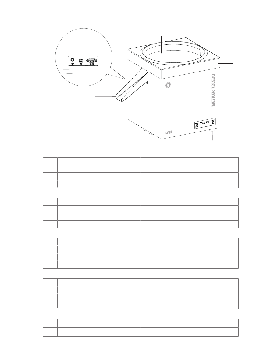
Legend device overview
Feeder plate
1
Housing
3
Rubber feet
5
Connection sockets
7
Legende Geräteübersicht
Förderteller
1
Gehäuse
3
Gummifüsse
5
Anschlussbuchsen
7
Leyenda de la visión general del dispositivo
Placa del alimentador
1
Carcasa
3
Patas de goma
5
Tomas de conexión
7
Légende – Présentation du dispositif
Plateau du vibreur
1
Boîtier
3
Pieds en caoutchouc
5
Prises de branchement
7
图例 设备概览
输料机板
1
外壳
3
Cover
2
Controls and indicators
4
Outlet chute
6
Abdeckung
2
Bedien- und Anzeigeelemente
4
Auslassrutsche
6
Cubierta
2
Controles e indicadores
4
Deslizadera de salida
6
Couvercle
2
Commandes et indicateurs
4
Glissière de sortie
6
保护罩
2
控件与指示灯
4
1
Page 4

橡胶支脚
5
连接插座
7
各部の名称
フィーダ プレート
1
ハウジング
3
ゴム足
5
接続ソケット
7
出口滑道
6
カバー
2
コントロールとインジケータ
4
排出シュート
6
2
Page 5

Operating Instructions Automatic Feeder
English
Bedienungsanleitung Automatikförderer
Instrucciones de manejo Alimentador automático
Mode d'emploi Vibreur automatique
产品说明书 自动进料机
取扱説明書 自動フィーダ
Deutsch
Español
Français
中文
日本語
Page 6

Page 7
1 Safety Information
• Read and understand the instructions in this manual before you use the device.
• Keep this manual for future reference.
• Include this manual if you pass on the device to other parties.
If the device is not used according to the instructions in this manual or if it is modified, the safety of
the user may be impaired and Mettler-Toledo GmbH assumes no liability.
1.1 Definition of signal words and warning symbols
Safety notes are marked with signal words and warning symbols. These show safety issues and
warnings. Ignoring the safety notes may lead to personal injury, damage to the instrument,
malfunctions and false results.
WARNING
CAUTION
NOTICE
Note
1.2 Product specific safety note
The device has been tested for the experiments and intended purposes documented in the appropriate
manual. However, this does not absolve you from the responsibility of performing your own tests of
the products supplied by us regarding their suitability for the methods and purposes you intend to use
them for.
Intended use
This device is designed to be used in quality testing laboratories by qualified staff. The LV12 is
intended to be used as automatic feeder for small parts (ø max. 20 mm) such as capsules, tablets
or small electronic and mechanical components.
Any other type of use and operation beyond the limits of technical specifications without written
consent from Mettler-Toledo GmbH, is considered as not intended.
Site requirements
The device has been developed for indoor operation. Avoid the following environmental influences:
• Conditions outside of the ambient conditions specified in the technical data
• Powerful vibrations
• Direct sunlight
• Corrosive gas atmosphere
• Explosive atmosphere of gases, steam, fog, dust and flammable dust
• Powerful electric or magnetic fields
for a hazardous situation with medium risk, possibly resulting in death or severe
injury if not avoided.
for a hazardous situation with low risk, resulting in minor or moderate injury if not
avoided.
for a hazardous situation with low risk, resulting in damage to the device, other
material damage, malfunctions and erroneous results, or loss of data.
(no symbol)
for useful information about the product.
General hazard Electrical shock
en
Safety Information 3Automatic Feeder
Page 8
Staff qualification
Incorrect use of the device or the chemicals used in the analysis can lead to death or injury. The
following experience is needed for operating the device.
• Knowledge and experience in working with toxic and caustic substances.
• Knowledge and experience in working with standard laboratory equipment.
• Knowledge and experience in working in accordance with general lab safety rules.
Responsibilities of the device owner
The device owner is the person that uses the device for commercial use or places the device at the
disposal of his staff. The device owner is responsible for product safety and the safety of staff, user(s)
and third party.
The operator has the following responsibilities:
• Know the rules for safety at the workplace that are in effect and enforce them.
• Ensure that only qualified staff uses the device.
• Define the responsibilities for installation, operation, cleaning, troubleshooting and maintenance
and ensure that the tasks are done.
• Train the staff in regular intervals and inform them about dangers.
• Provide the necessary protective gear for the staff.
Safety notes
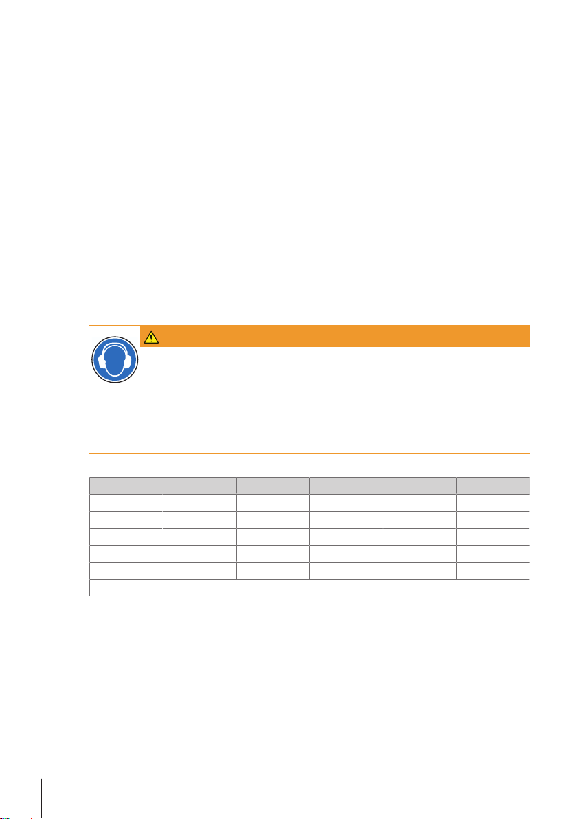
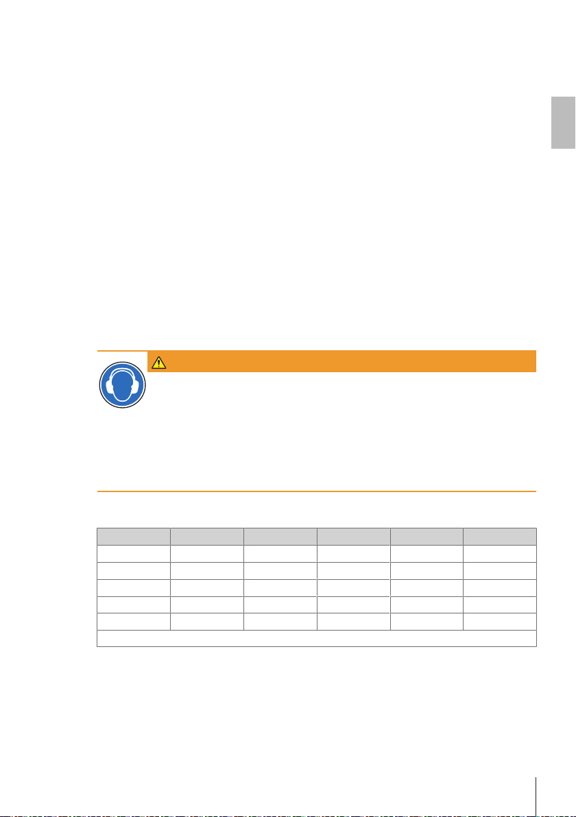
WARNING
Risk of hearing impairment due to high noise level!
Depending on the used samples (material and weight), potentially hazardous noise
levels may occur when samples fall down on the outlet chute. A noise level above
80db(A) may result in serious damage to hearing.
1 If you feed parts where you expect the noise level to be above 80 db(A), perform a
noise measurement. Take the examples below as references.
2 Wear ear protection if the noise level exceeds 80 db(A).
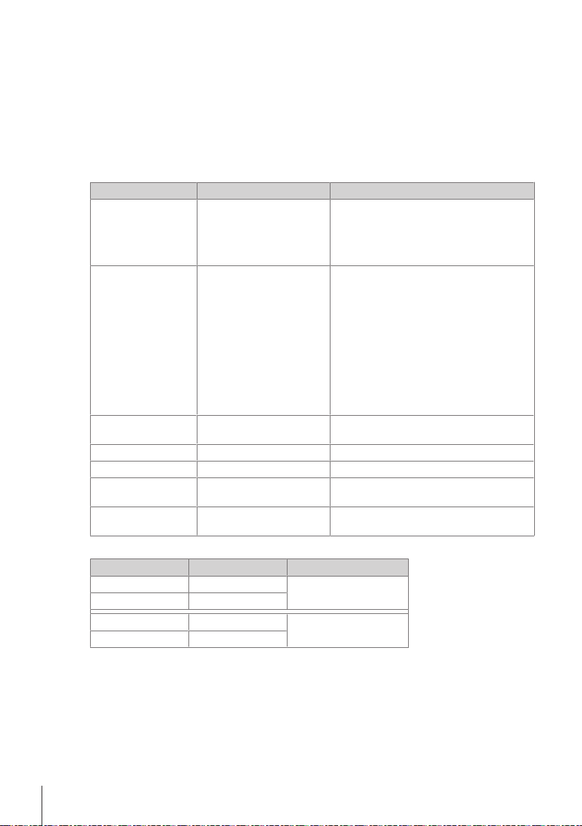
The following list provides approximate values of noise emissions (discharge mode, 20 cm):
Settings Item Material Weight Size Value
General Spacer Synthetical 0.12 g 10 × 5 mm
Small Screw Metal 0.14 g M2 × 3 mm
Medium Screw Metal 0.2 g M2.5 × 5 mm
Large Distance holder Metal 1.5 g M3 × 10 mm
Large Distance holder Metal 5.1 g M4 × 20 mm
Empty: < 70 db(A)
78 dB(A)
75 dB(A)
79 dB(A)
89 dB(A)
93 dB(A)
Safety Information4 Automatic Feeder
Page 9

NOTICE
Danger of damage due to inappropriate use!
Inappropriate use of the instrument may lead to significant material damage.
1 Install and operate the instrument only in dry interior rooms.
2 Always operate and use the device only in accordance with the instructions
contained in this manual.
3 Do not open the device.
4 Never make any modifications to the device.
5 Use only instrument accessories and peripheral devices from METTLER TOLEDO;
they are optimally adapted to your instrument.
en
Safety Information 5Automatic Feeder
Page 10
2 Design and Function
The LV12 is an automatic feeder for capsules, tablets or small electronic and mechanical
components. Large weighing series are radically simplified. The LV12 is therefore especially suitable
for statistical quality control (SQC). Usually the LV12 is remotely controlled by commands over a
serial interface (RS232 or USB), but the system can also be controlled manually using push buttons.
The LV12 delivers a single part to the balance and then stops automatically. After receiving the appropriate command from the weighing instrument, the device delivers the next part. This process can be
stopped at any time by a command. At the end of a sample, the feeder plate can be emptied or the
feeder waits for the command for a further sample.
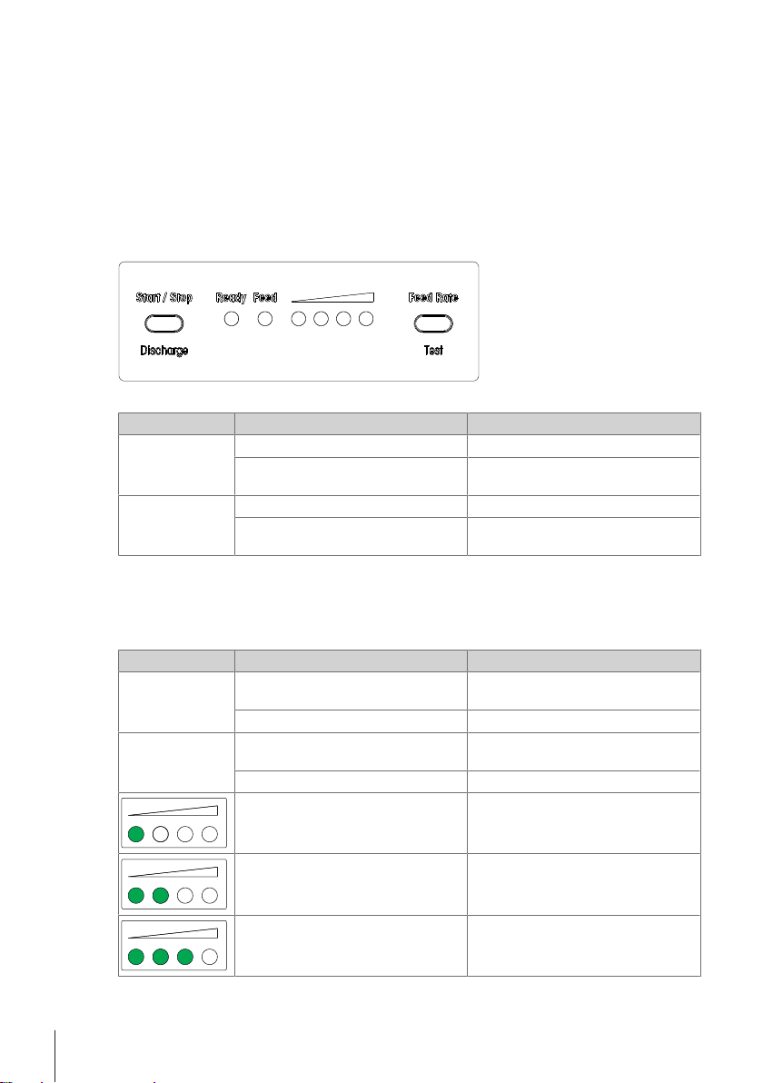
2.1 Controls and indicators
Controls
Button Action Objective
Start/Stop/
Discharge
Feed Rate/Test
Note
By pressing both buttons at the same time, the part size setting can be changed, see [Configure
feeding rate sets}Page17].
Indicators
LED indicator State Meaning
Ready
Feed
Press once To switch feeding action on/off
Press and hold until the level indicating
LEDs flash
Press once Change feed rate by one step
Press and hold until the LED Ready
flashes
Green LED lit up Instrument is switched on and ready for
Green LED flashes Instrument is in test mode
Orange LED lit up Feeding action is switched on and the
Orange LED flashes Light barrier is interrupted, dirty or faulty
One LED lit up Lowest feed rate
To switch on discharge
Activate the test mode to find the optimal
feed rate
operation
feeder plate vibrates
Two LEDs lit up Lower intermediate feed rate, default after
Three LEDs lit up Upper intermediate feed rate
switching on
Design and Function6 Automatic Feeder
Page 11
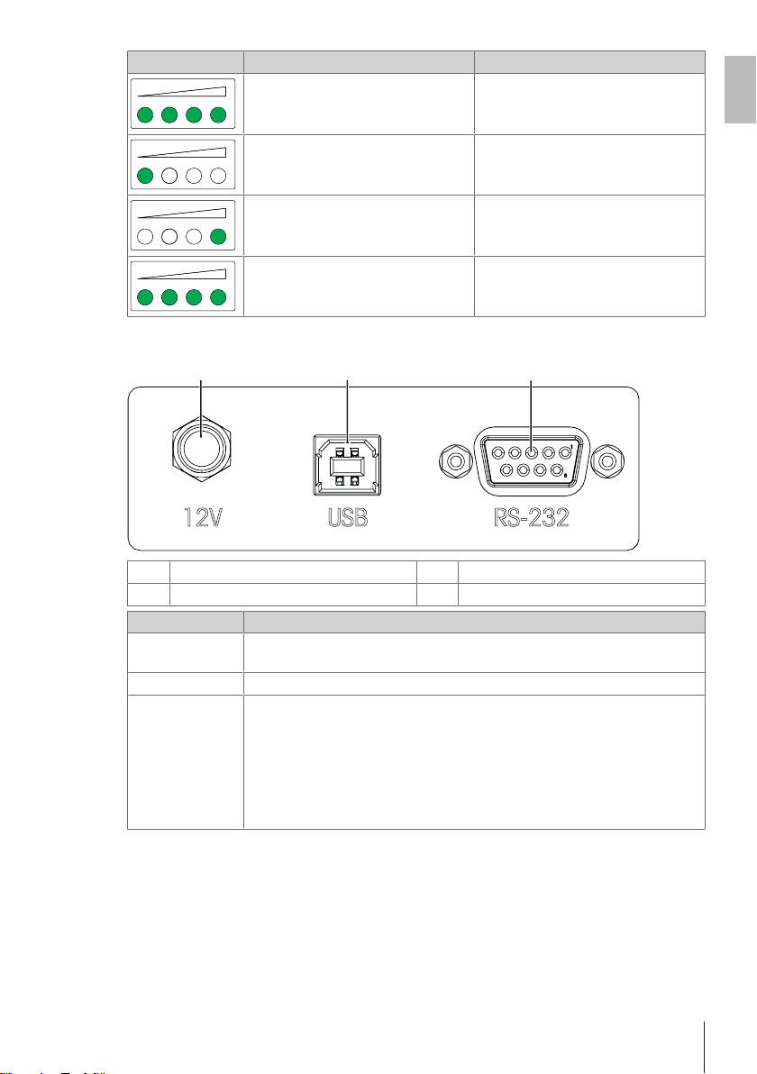
LED indicator State Meaning
1 2
3
All four LEDs lit up Highest feed rate
en
2.2 Connections
Socket for 12VDC power supply
1
RS232 interface
3
Connector Function
Socket for AC/DC
adapter
USB port (type B)
RS232 interface
Note
For the SICS command set of the LV12, see [MT-SICS interface commands and
functions}Page20].
First LED flashes
Fourth LED flashes
All Four LEDs flashes Instrument is in discharging mode
2
To connect the power supply. Use only the +12VDC standard AC/DC adapter which
is delivered with the device.
To connect a balance, a personal computer or a hub provided with an USB port.
The connection for RS232 is a 9-pin D-sub miniature connector, pin assignment as
for PCs. For the attachment of a computer, a so-called laplink or null modem cable
is needed.
Interface parameters:
• 9600 baud, no parity, 8 data bits, 1 stop bit
• Software handshake Xon/Xoff
• Line ending <CR><LF>
Short circuit at Start/Stop/Discharge
button
Short circuit at Feed Rate/Test button
USB port (type B)
Design and Function 7Automatic Feeder
Page 12
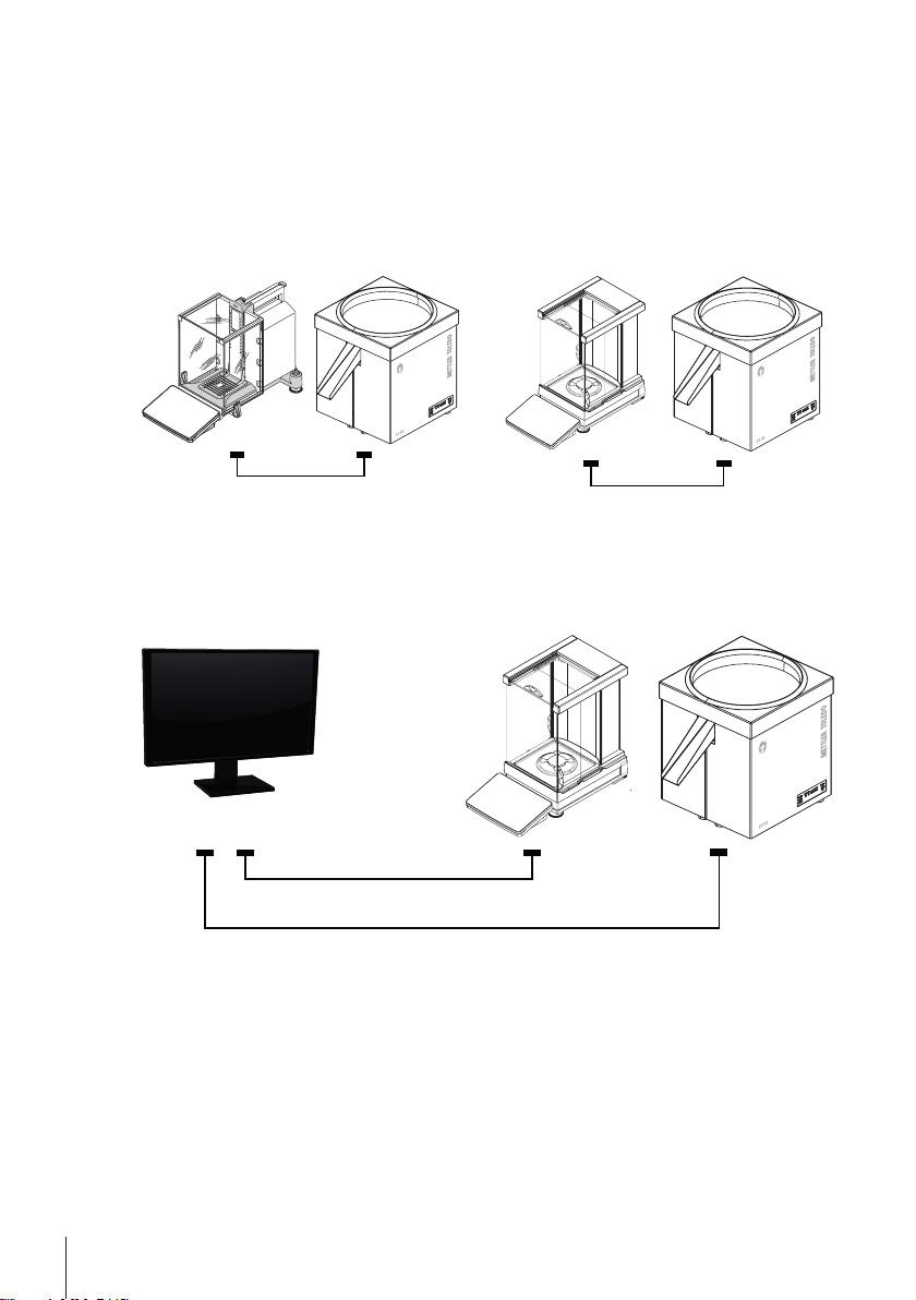
2.3 Operating modes
RS232
www.mt.co
m
X
PE204
F
F
METTLER TOLEDO
S
tatic
D
ete
c
t
USB (A/B)
USB
A
USB B
IND
890SQC
RS232
USB (A/B)
USB
A
USB B
Following system setups are supported by the LV12:
XP/XPE balances with RS232 connection XPR balances with USB connection
LV12 can be controlled by a METTLER TOLEDO
XP/XPE balance with RS232 interface. The
program for the control must be available in the
weighing instrument (e. g. SQC or statistics
application in Excellence balance).
IND890SQC direct connection
LV12 and balance are directly connected to an IND890SQC system (LV12 by RS232, balance by
USB).
LV12 can be controlled by a METTLER TOLEDO
XPR balance with USB interface.
Design and Function8 Automatic Feeder
Page 13
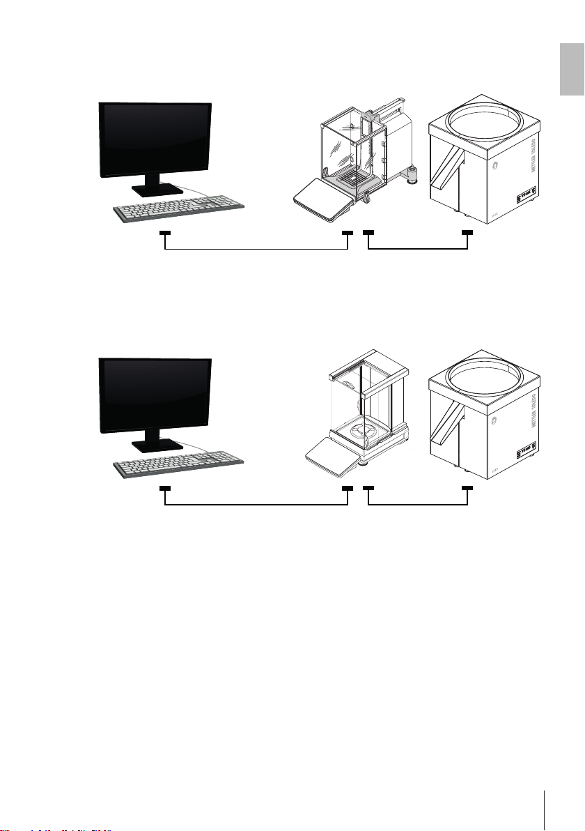
LabX or Freeweigh.net with XP, XPE balances
RS232
Ethernet or RS232
LabX
Freeweigh
.net
www.mt.co
m
X
PE204
F
F
METTLER TOLEDO
S
tatic
D
ete
c
t
USB (A/B)
Ethernet or USB (A/B)
La
bX
• XP/XPE balance connected to PC by Ethernet or with RS232 cable.
• LV12 connected to XP/XPE balance with RS232 interface.
LabX with XPR balances
• XPR balance connected to PC by Ethernet or with USB cable.
• LV12 connected to XPR balance with USB interface.
en
Design and Function 9Automatic Feeder
Page 14

3 Installation and Putting into Operation
This section describes how to set the new instrument into operation.
3.1 Unpacking the device
Delivery
The device is delivered by a local logistics company. All the components included in the scope of
delivery are delivered together in a single package.
Transport damages or missing parts
On receipt of the delivery, check it without delay to ensure that it is complete and undamaged.
If there is any visible external transport damage, proceed as follows:
• Do not accept the delivery.
• Make a note of the scope of damage on the carrier's delivery note.
• Inform a METTLER TOLEDO representative.
Note
Lodge a complaint for each defect as soon as it is identified. Claims for damages can only be made
within the applicable claim periods.
Unpacking device
Proceed as follows to unpack the device:
1 Open the packaging box.
2 Remove the package lifting it on the belt strap.
3 Remove the belt strap around the foam elements.
4 Remove the polystyrene element on the top of the device.
5 Unpack the feeder plate and the plastic cover.
6 Remove the upper foam element.
7 Lift and remove the device from the lower foam element.
8 Remove the belt strap fixing the device.
9 Check the device for transportation damages or missing parts.
10 To assemble the device, proceed as described in [Assembling the device}Page11].
Note
We recommend retaining all parts of the packaging. The packaging offers the best protection for
transporting the device over long distances.
3.2 Scope of delivery
• LV12 including chute
• Power supply 60 W/12 VDC with country-specific power cable
• RS232 cable (m/f, 1.0 m) to connect a balance
• USB cable (A/B, 1.0 m) to connect a PC or balance
• Operating instructions printed
• CD-ROM containing USB drivers and operating instructions
• EC declaration of conformity
3.3 Selecting the location
An optimal location will ensure accurate and reliable operation of the device. The following local
conditions must be observed:
Installation and Putting into Operation10 Automatic Feeder
Page 15
Observe the ambient conditions:
1
2
• The instrument must only be used indoors and up to a
maximum altitude of 5000 m above sea level.
• Temperature range: 10–30 °C
• Humidity: max. 80% noncondensing
Pay attention the following:
• The power plug must be accessible at all times.
• Firm, horizontal and vibration-free location.
• Avoid excessive temperature fluctuations.
• Avoid direct sunlight.
• No powerful drafts (e. g. from fans or air conditioners).
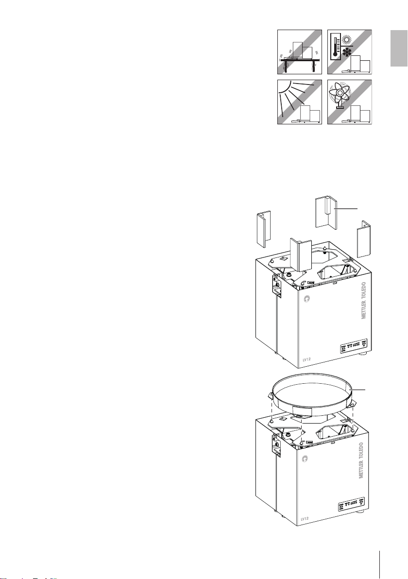
3.4 Assembling the device
After checking the scope of delivery, unpacking the device and after finding a proper location, the
device must be assembled.
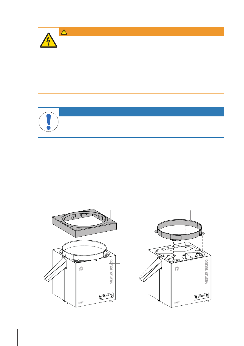
1 Remove the four transportation locks (1) (one in each
corner).
en
2 Put the feeder plate (2) on the device and fix it by turning it
clockwise along the slotted holes.
Installation and Putting into Operation 11Automatic Feeder
Page 16
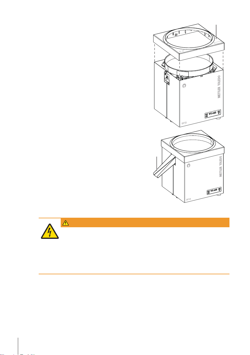
3 Put the cover (3) on the device. Take the marks on the top
3
4
of cover as reference for the correct orientation (the marks
have to point to the front as indicated in the image). Push
the cover down until it snaps into place.
4 Fit the chute (4) to the two clamping blots at the lateral
opening and push it in as far as it will go.
5 Connect the device to the balance using the delivered
cables (either by USB or RS232 according to the used
balance).
6 Set up the device as described in [Connecting the
device}Page12].
3.5 Connecting the device
WARNING
Risk of electric shock
1 To connect the device, only use the supplied three-core power cable with equipment
grounding conductor.
2 Only connect the device to a three-pin power socket with earthing contact.
3 Only standardized extension cable with equipment grounding conductor must be
used for operation of the device.
4 Intentional disconnection of the equipment grounding conductor is forbidden.
Installation and Putting into Operation12 Automatic Feeder
Page 17

NOTICE
Property damage due to short circuit!
Damage to the insulation on the AC/DC adapter or the cable can result in a short-circuit
and damage the device.
1 Only use the original AC/DC adapter which was supplied with your device.
Otherwise, the device may get damaged.
2 If the AC/DC adapter or the cable is damaged, pull out the power plug and have the
AC/DC adapter replaced.
3 Route the cable so that it cannot be damaged by external influences.
4 The power plug must always be accessible.
5 Keep moisture away from live parts. Moisture can result in short-circuit.
Note
When the device is connected to the mains, it starts automatically. To switch off the device and to
disconnect it from the power supply, the mains plug has to be plugged out.
The device is supplied with an AC/DC adapter and a country-specific power cable. The AC/DC adapter
is suitable for use with the following voltage range:
100 – 240 VAC, 50/60Hz.
Proceed as follows to connect and set up the device:
1 Position the device on a firm surface. Pay attention to the required ambient conditions, see
[Selecting the location}Page10].
2 Check the AC/DC adapter and the cable for damage.
3 Check whether your local power supply falls within the range of the delivered AC/DC adapter. If
this is not the case, under no circumstances connect the AC/DC adapter to the power supply, but
contact a METTLER TOLEDO representative.
en
Installation and Putting into Operation 13Automatic Feeder
Page 18
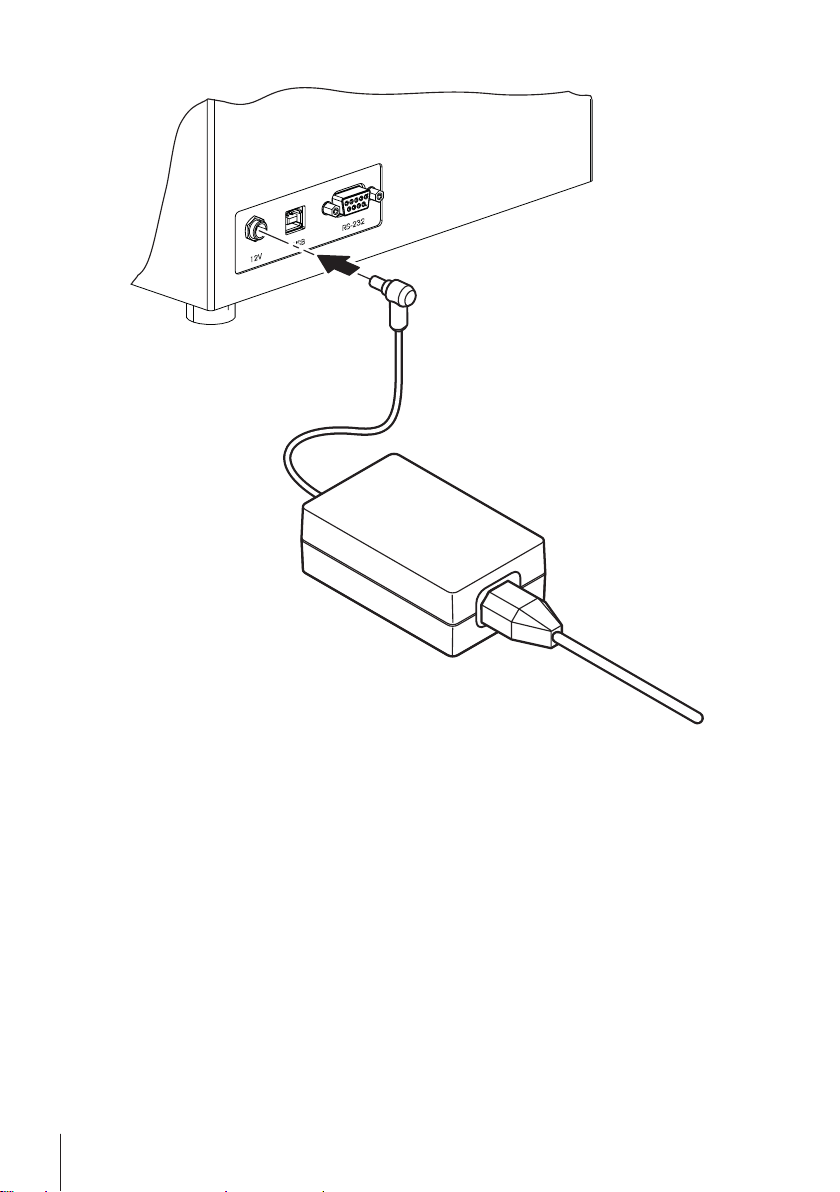
4 Connect the AC/DC adapter to the connection socket at the rear of the device.
5 Connect the AC/DC adapter to a grounded electrical outlet.
ð When the LV12 is connected to the mains supply, an initialization (reset) runs for approx. 2
seconds. During this time, all LEDs light up. The instrument is then in the normal mode with preselected intensity level2.
Note
• The basic setting of the vibration is selected so that most parts can be delivered without any
problems. For very small or large parts, this setting can be adjusted, see [Configure feeding rate
sets}Page17].
Installation and Putting into Operation14 Automatic Feeder
Page 19

3.6 Transporting the device
NOTICE
Risk of property damage due to improper transport!
In the event of improper transport, the device may fall. This can cause major property
damage.
1 Only transport the device when it is disconnected from the mains supply.
2 If you would like to transport or ship your device over long distances, use the
complete original packaging.
3 Always transport packages upright and never throw them.
Remove the power cable and any interface cable from the device. Refer to the notes in section
[Selecting the location}Page10] regarding the choice of an optimal location.
en
Installation and Putting into Operation 15Automatic Feeder
Page 20
4 Operation
4.1 Starting/stopping feeding
Usually the LV12 is remotely controlled by commands over a serial interface (RS232 or USB), but the
device can also be controlled manually. To start or stop the feeding action manually, proceed as
follows:
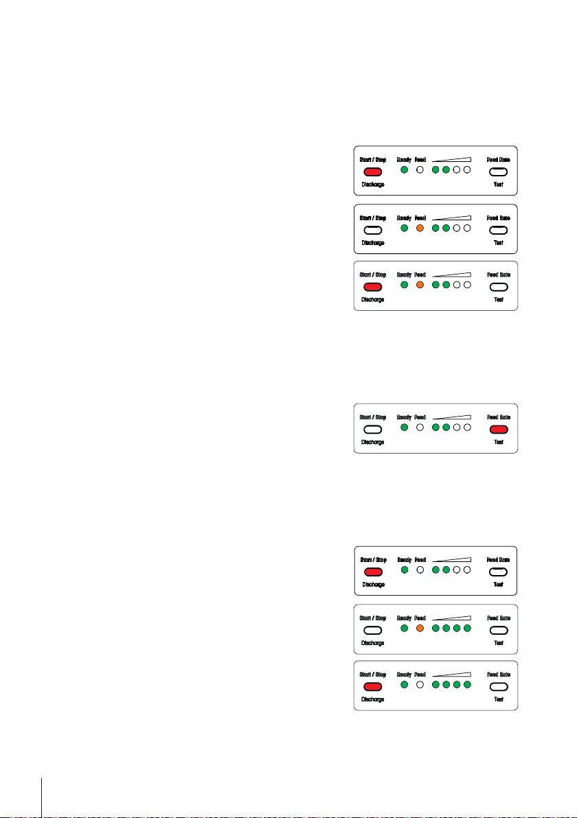
The device is in state "ready" (LED Ready is lit up).
§
1 Press once the button Start/Stop/Discharge.
ð Feeding action starts. The orange LED Feed lights up.
2 Press the button Start/Stop/Discharge anew to stop
feeding action. If feeding is not stopped manually, the
system feeds until an object interrupts the light barrier and
then stops automatically.
4.2 Adjusting feeding rate
The feeding rate can be adjusted before starting or during the feeding process. Changing the feeding
rate during the feeding process takes effect immediately. Proceed as follows to change the feeding
rate:
The device is in state "ready" (LED Ready is lit up).
§
− By briefly pressing the button Feed Rate/Test, you can
adjust the feeding rate so that only one part at a time falls
onto the balance.
4.3 Discharging device
Discharge is used to empty the system of all objects. The system feeds at the configured discharge
feed rate and stops 90 seconds after the last object has passed the light barrier. Proceed as follows
to activate discharge:
The device is in state "ready" (LED Ready is lit up).
§
1 Press and hold the button Start/Stop/Discharge for at least
2 seconds.
ð Discharge action starts. The orange LED Feed lights up
and all four level indicating LEDs flash.
2 To stop discharging manually, press once the button Start/
Stop/Discharge. Otherwise, discharging will stop automatically.
Operation16 Automatic Feeder
Page 21
4.4 Find optimal feeding rate
The test mode allows you to find the optimal feeding rate and therefore to ensure, that only one part at
a time is fed to the balance. Proceed as follows to adjust the feeding rate using the test mode:
The device is in state "ready" (LED Ready is lit up).
§
1 To enter the test mode, press and hold the button Feed
Rate/Test for at least 5 seconds.
ð The LV12 starts delivery until a part passes through the
light barrier. It then stops for 2.5 seconds and then
continues delivery until the next passage through the
light barrier.
2 By briefly pressing the button Feed Rate/Test, you can now
select the rate so that only one part at a time falls onto the
balance.
3 To quit the test mode, press the button Start/Stop/
Discharge.
4.5 Configure feeding rate sets
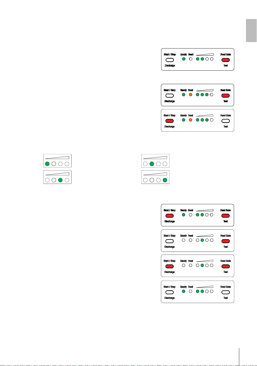
During the configuration, the intensity level is indicated by the four green LEDs as follows:
General (for most parts, factory
settings)
Midsize parts Large parts
To configure the feeding rate set, proceed as follows:
The device is in state "ready" (LED Ready is lit up).
§
1 Press and hold the two buttons for at least 5 seconds.
ð The LED Ready goes out.
Small parts
en
2 Change the feeding rate set by toggling using the button
Feed Rate/Test.
3 To quit the setting mode, press anew the two buttons.
ð The LED Ready is lit up.
Operation 17Automatic Feeder
Page 22
5 Maintenance
2
3
1
WARNING
Danger of death or serious injury due to electric shock!
Contact with parts that contain a live current can lead to injury and death. If the device
cannot be shut down in an emergency situations, people can be injured or the device
can be damaged.
1 Disconnect the device from the power supply prior to cleaning and maintenance.
2 Only use METTLER TOLEDO power cable, if these need to be replaced.
3 Make sure that no liquid enters into the device or AC/DC adapter.
4 Do not open the device or AC/DC adapter.
These contain no user-serviceable parts.
5.1 Cleaning
NOTICE
Damage of the device due to the use of inappropriate cleaning agents!
− On no account use cleaning agents which contain solvents or abrasive ingredients,
as this can result in damage to the device.
Clean the housing regularly with a damp, soft cloth. The feeder plate is made of stainless chrome
steel and can be removed for cleaning as follows:
1 Disconnect power plug.
2 Press slightly together the side walls of the housing (1) and simultaneously lift off the plastic
cover (2).
3 Detach the feeder plate (3) by turning it counter clockwise along the slotted holes.
4 Clean all contaminated parts using a mild cleaning agent.
5 After cleaning, put the feeder plate and the plastic cover back on the device. Pay attention to the
correct orientation of the cover (the marks on top of the cover have to point to the front).
Maintenance18 Automatic Feeder
Page 23

5.2 Disposal
In conformance with the European Directive 2012/19/EU on Waste Electrical and
Electronic Equipment (WEEE) this device may not be disposed of in domestic waste. This
also applies to countries outside the EU, per their specific requirements.
Please dispose of this product in accordance with local regulations at the collecting point
specified for electrical and electronic equipment. If you have any questions, please
contact the responsible authority or the distributor from which you purchased this device.
Should this device be passed on to other parties (for private or professional use), the
content of this regulation must also be related.
Thank you for your contribution to environmental protection.
en
Maintenance 19Automatic Feeder
Page 24
6 MT-SICS interface commands and functions
The device is capable of integration in a complex computer or data acquisition system.
To enable you to integrate the device in your system in a simple manner and utilize its capabilities to
the full, most functions are also available as appropriate commands via the data interface. Therefore,
the device supports the standardized command set "METTLER TOLEDO Standard Interface Command
Set" (MT-SICS).
The following table gives a short overview about the commands available for LV12. For further information please contact your METTLER TOLEDO representative.
MT-SICS commands
MT-SICS command MT-SICS command header Description
LV01 Software Restart The software is restarted just as it was in the
LV02 >Level< Feed Rate Sets the actual feed rate intensity to a specific
LV03 Vibrate until Light Barrier
Signal
LV04 Vibrate until Stop or Reset Vibrate until stop or reset.
LV05 Discharge Discharge device.
LV06 Stop Stops the current action and brings the device
LV99 Light Barrier Signal Status changes of the light barrier results in this
Light barrier signal
Action Syntax Description
Query LV99 Light barrier is free
Response LV99 A
Query LV99 Light barrier is blocked
Response LV99 B
case of power on. This command brings the
device back to the power-up state. Power-up
state means, that the device is ready and feed
rate is set to level 2. Feeding rate set remains.
level.
Feed rate level.
{Data type: unsigned 8 bits. Range see below}
• Value: '1' → Feed rate level 1
• Value: '2' → Feed rate level 2
• Value: '3' → Feed rate level 3
• Value: '4' → Feed rate level 4
The initial value is given by the software of the
device (initial value is feed rate level 2).
Vibrate until light barrier signal.
back to the ready state.
command. For details see the table below.
Pay attention to the following:
• All commands must be closed with <CR> and <LF>.
• The system responds to an unknown command with "ES".
• The device may response unsolicited (e. g. by manual operation and startup)
MT-SICS interface commands and functions20 Automatic Feeder
Page 25

7 Technical Data
7.1 General data
WARNING
Danger of death or serious injury due to electric shock!
Contact with parts that contain a live current can lead to injury and death.
1 Only use an approved AC/DC adapter with a current-limited SELV output.
2 Ensure correct polarity
Power supply
AC/DC adapter: Primary: 100 – 240VAC, 50/60 Hz
Secondary: 12VDC ±5%, 5A max (with electronic overload
protection)
Device power supply: 12 VDC ±5%, 0.9 A
Protection and standards
Overvoltage category: II
Degree of pollution: 2
Protection: Only use indoors in dry locations
Standards for safety and EMC: See Declaration of Conformity
Range of application: For use only in closed interior rooms
Environmental conditions
Height above mean sea level: Up to 5000m
Ambient temperature: 10–30°C
Relative air humidity: Max. 80% noncondensing
Weight and Dimensions
W x H x D 225 x 260 x 225 mm
Net weight 10.9 kg
Admissible part size ø 1 mm up to ø 20 mm
en
Technical Data 21Automatic Feeder
Page 26
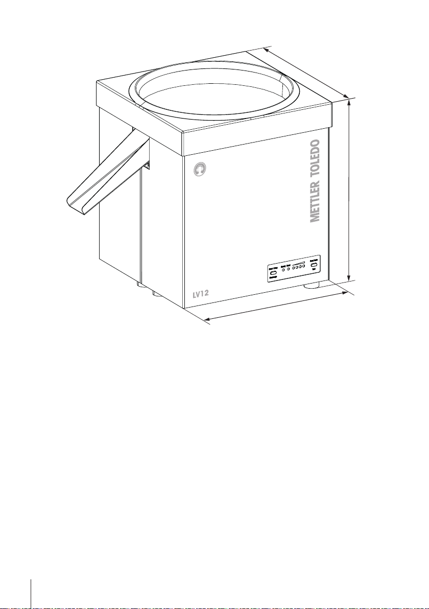
7.2 Dimensions
225 mm
225 mm
260 mm
Technical Data22 Automatic Feeder
Page 27
8 Accessories and Spare Parts
Country-specific 3-Pin power cable with grounding
conductor.
Power cable AU 00088751
Power cable BR 30015268
Power cable CH 00087920
Power cable CN 30047293
Power cable DK 00087452
Power cable EU 00087925
Power cable GB 00089405
Power cable IL 00225297
Power cable IN 11600569
Power cable IT 00087457
Power cable JP 11107881
Power cable TH, PE 11107880
Power cable US 00088668
Power cable ZA 00089728
USB (A/B): connection cable for PC/balance, 1.0 m
(included in the standard equipment)
en
30388322
RS232 (m/f, 1:1): connection cable for balance, 1.0 m
(included in the standard equipment)
RS232 (f/f, Nullmodem): connection cable for PC, 1.8 m 21900576
Chute (included in the standard equipment) 30388039
Power supply 60 W/12VDC (included in the standard
equipment)
11101051
30388323
Available on request:
Door with opening, for Excellence analytical balances 11106715
Door with opening, for Excellence precision balances with high draft shield 11132711
Accessories and Spare Parts 23Automatic Feeder
Page 28
1 Sicherheitshinweise
• Bitte machen Sie sich mit den Anweisungen in dieser Bedienungsanleitung vertraut, ehe Sie das
Gerät verwenden.
• Heben Sie diese Anleitung zur späteren Verwendung auf.
• Bitte legen Sie auch dieses Handbuch bei, wenn Sie das Gerät anderen zur Verfügung stellen.
Wenn das Gerät modifiziert oder nicht gemäss den Anweisungen in dieser Anleitung verwendet wird,
können Gefahren für den Benutzer entstehen. Mettler-Toledo GmbH keinerlei Haftung.
1.1 Definition von Signalwörtern und Warnsymbolen
Sicherheitshinweise sind mit Signalwörtern und Warnbildsymbolen gekennzeichnet. Sie kennzeichnen
Sicherheitsrisiken und Warnungen. Die Missachtung der Sicherheitshinweise kann zu persönlicher
Gefährdung, Beschädigung des Geräts, Fehlfunktionen und falschen Ergebnissen führen.
WARNUNG
VORSICHT
HINWEIS
Hinweis
1.2 Produktspezifischer Sicherheitshinweis
Das Gerät wurde für die in der jeweiligen Anleitung dokumentierten Anwendungen und vorgesehenen
Verwendungszwecke getestet. Dennoch liegt es in Ihrer Verantwortung, mittels eigener Tests zu überprüfen, ob sich die von uns gelieferten Produkte wirklich für die Verfahren und Zwecke eignen, für die
Sie sie verwenden wollen.
Bestimmungsgemässe Verwendung
Dieses Gerät wurde dafür entwickelt, von qualifiziertem Personal in Prüflaboren verwendet zu werden.
Der LV12 ist vorgesehen als Automatikförderer für Kleinteile (ø max. 20 mm), wie beispielsweise
Kapseln, Tabletten oder kleine elektronische oder mechanische Komponenten, benutzt zu werden.
Jegliche anderweitige Verwendung, die über die Grenzen der technischen Spezifikationen hinausgeht,
gilt ohne schriftliche Absprache mit der Mettler-Toledo GmbHals nicht bestimmungsgemäss.
Anforderungen vor Ort
Das Gerät wurde für die Verwendung in Innenbereichen entwickelt. Schliessen Sie folgende Umwelteinflüsse aus:
• Bedingungen, die nicht den in den technischen Daten genannten Umgebungsbedingungen ent-
sprechen
• Starke Vibrationen
• Direkte Sonneneinstrahlung
• Korrosive Gasatmosphären
• Explosionsgefährdete Gas-, Dampf-, Nebel- und Staubatmosphären bzw. entflammbare Staubat-
mosphären
• Starke elektrische oder magnetische Felder
Eine Gefährdung mit mittlerem Risiko, die möglicherweise zum Tod oder zu schweren Körperverletzungen führen kann, wenn sie nicht vermieden wird.
Eine gefährliche Situation mit niedrigem Risiko, die leichte oder mittelschwere Verletzungen zur Folge haben kann, wenn sie nicht vermieden wird.
Eine gefährliche Situation mit niedrigem Risiko, die eine Beschädigung des Geräts,
Materialschäden, Fehlfunktionen und falsche Resultate oder Datenverlust zur Folge
haben kann.
(kein Symbol)
allgemeine Informationen zum Produkt.
Allgemeine Gefahr Stromschlag
Sicherheitshinweise24 Automatikförderer
Page 29
Mitarbeiterqualifikation
Eine unsachgemässe Verwendung des Geräts oder der im Rahmen der Analyse verwendeten Chemikalien kann zum Tod oder zu Verletzungen führen. Für die Bedienung des Geräts sind die folgenden
Qualifikationen erforderlich:
• Kenntnisse und Erfahrung im Umgang mit toxischen und ätzenden Substanzen.
• Kenntnisse und Erfahrung im Umgang mit standardmässiger Laborausrüstung.
• Kenntnisse und Erfahrung im Hinblick auf die Einhaltung allgemeiner Laborsicherheitsbestimmun-
gen.
Verantwortlichkeiten des Gerätebesitzers
Der Gerätebesitzer ist diejenige Person, welche das Gerät für kommerzielle Zwecke nutzt oder es ihren
Mitarbeitern zur Verfügung stellt. Der Gerätebesitzer ist für die Produktsicherheit sowie für die Sicherheit von Mitarbeitern, Benutzern und Dritten verantwortlich.
Der Gerätebesitzer hat folgende Verantwortlichkeiten:
• Die geltenden Regeln für die Sicherheit am Arbeitsplatz kennen und diese durchsetzen.
• Sicherstellen, dass das Gerät nur von qualifizierten Mitarbeitern verwendet wird.
• Die Zuständigkeiten im Hinblick auf Installation, Bedienung, Reinigung, Fehlerbehebung und War-
tung festlegen und sicherstellen, dass diese Aufgaben ausgeführt werden.
• Die Mitarbeiter regelmässig schulen und sie über Gefahren informieren.
• Den Mitarbeitern die erforderliche Schutzausrüstung zur Verfügung stellen.
Sicherheitshinweise
WARNUNG
Risiko von Gehörschädigungen durch hohen Lärmpegel!
Je nach verwendeten Proben (Material und Gewicht) kann ein hoher Lärmpegel entstehen, wenn die Proben aus der Auslassrutsche fallen. Ein Lärmpegel von über 80db(A)
kann zu einer schweren Gehörschädigung führen.
1 Wenn Sie Teile zuführen, bei denen ein Lärmpegel von über 80 db(A) zu erwarten
ist, sollten Sie eine Lärmmessung vornehmen. Die nachstehenden Beispiele dienen
als Referenzwerte.
2 Tragen Sie einen Gehörschutz, wenn der Lärmpegel 80 db(A) überschreitet.
de
In der folgenden Liste werden ungefähre Werte für Lärmemissionen (Entleerungsmodus, 20cm) aufgeführt:
Einstellungen Artikel Material Gewicht Grösse Wert
Allgemein Distanzhalter Kunststoff 0,12 g 10 × 5 mm
Klein Schraube Metall 0,14 g M2 × 3 mm
Mittel Schraube Metall 0,2 g M2,5 × 5 mm
Gross Abstandhalter Metall 1,5 g M3 × 10 mm
Gross Abstandhalter Metall 5,1 g M4 × 20 mm
Leer: < 70 db(A)
78 dB(A)
75 dB(A)
79 dB(A)
89 dB(A)
93 dB(A)
Sicherheitshinweise 25Automatikförderer
Page 30

HINWEIS
Es besteht die Gefahr einer Beschädigung durch unsachgemässe Verwendung!
Eine unsachgemässe Verwendung des Instruments kann zu erheblichen Materialschäden führen.
1 Installieren und betreiben Sie das Instrument nur in trockenen Innenräumen.
2 Bedienen und verwenden Sie das Gerät nur unter Berücksichtigung der Anweisun-
gen in diesem Handbuch.
3 Öffnen Sie das Gerät nicht.
4 Nehmen Sie keine Veränderungen am Gerät vor.
5 Verwenden Sie mit Ihrem Instrument ausschliesslich Zubehör und Peripheriegeräte
von METTLER TOLEDO, diese sind optimal auf Ihr Instrument abgestimmt.
Sicherheitshinweise26 Automatikförderer
Page 31

2 Aufbau und Funktion
Der LV12 ist ein Automatikförderer für Kapseln, Tabletten oder kleine elektronische bzw. mechanische
Komponenten. Grosse Wägeserien werden radikal vereinfacht. Der LV12 ist deshalb insbesondere für
die statistische Qualitätskontrolle (SQC) geeignet. In der Regel wird der LV12 mittels Befehlen über
eine serielle Schnittstelle (RS232 oder USB) ferngesteuert; das System kann aber auch manuell über
Drucktasten gesteuert werden.
Der LV12 fördert ein Einzelteil zur Waage und stoppt dann automatisch. Nach Erhalt eines entsprechenden Befehls von der Waage liefert das Gerät das nächste Einzelteil. Dieser Vorgang kann durch
einen Befehl jederzeit gestoppt werden. Am Ende einer Probe kann der Förderteller geleert werden oder
der Förderer wartet auf den Befehl für eine weitere Probe.
2.1 Bedien- und Anzeigeelemente
Bedienelemente
Taste Arbeitsschritt Zielsetzung
Start/Std.Adj./Ent-
leeren
Fördergeschwindigkeit/Test
Hinweis
Durch gleichzeitiges Drücken beider Tasten kann die Einstellung für die Grösse der Teile geändert
werden, siehe [Einstellungen für die Zuführrate konfigurieren}Seite38].
Anzeigen
LED-Anzeige Zustand Bedeutung
Bereit
Zuführen
Einmal drücken Zuführen einschalten/ausschalten
Gedrückt halten, bis zustandsanzeigende
LEDs aufleuchten
Einmal drücken Zuführrate um eine Stufe ändern
Gedrückt halten, bis LED Bereit auf-
leuchtet
Grüne LED leuchtet Gerät ist eingeschaltet und betriebsbereit
Grüne LED blinkt Gerät ist im Testmodus
Orange LED leuchtet Zuführen ist eingeschaltet und der Förder-
Orange LED blinkt Lichtschranke ist unterbrochen, ver-
Eine LED leuchtet Niedrigste Zuführrate
Entleeren einschalten
Testmodus aktivieren, um die optimale
Zuführrate zu bestimmen
teller vibriert
schmutzt oder defekt
de
Zwei LEDs leuchten Untere mittlere Zuführrate, Standardein-
Drei LEDs leuchten Obere mittlere Zuführrate
stellung nach dem Einschalten
Aufbau und Funktion 27Automatikförderer
Page 32

LED-Anzeige Zustand Bedeutung
1 2
3
Alle vier LEDs leuchten Höchste Zuführrate
Erste LED leuchtet
Vierte LED blinkt
Alle vier LEDs blinken Instrument ist im Entleeren-Modus
Kurzschluss bei Start/Std.Adj./Entlee-
ren-Taste
Kurzschluss bei Fördergeschwindigkeit/
Test-Taste
2.2 Anschlüsse
Anschluss für Stromversorgung (12VDC)
1
RS232-Schnittstelle
3
Anschluss Funktion
Anschluss für
Netzadapter
USB-Port (Typ B)
RS232-Schnitt-
stelle
An die Stromversorgung anschliessen. Nur mit Standard-Netzadapter (+12VDC)
betreiben, der im Lieferumfang enthalten ist.
An eine Waage, einen PC oder einen Hub (mit USB-Port) anschliessen.
Der RS232-Anschluss ist eine 9-polige D-Sub-Buchse mit Pinbelegung wie ein PC.
Für den Anschluss an einen Computer wird ein sogenanntes Laplink- oder Nullmodemkabel benötigt.
Schnittstellenparameter:
• 9600 Baud, keine Parität, 8 Datenbits, 1 Stoppbit
• Software-Handshake (Xon/Xoff)
• Zeilenende <CR><LF>
Hinweis
Zum SICS-Befehlssatz für den LV12, siehe [Schnittstellenbefehle und -funktionen MTSICS}Seite41].
2
USB-Port (Typ B)
Aufbau und Funktion28 Automatikförderer
Page 33

2.3 Betriebsarten
RS232
www.mt.co
m
X
PE204
F
F
METTLER TOLEDO
S
tatic
D
ete
c
t
USB (A/B)
USB
A
USB B
IND
890SQC
RS232
USB (A/B)
USB
A
USB B
Folgende System-Setups werden vom LV12 unterstützt:
XP/XPE-Waagen mit RS232-Anschluss XPR-Waagen mit USB-Anschluss
Der LV12 kann von einer XP/XPE-Waage von
METTLER TOLEDO mit RS232-Schnittstelle
gesteuert werden. Das Programm zur Steuerung
muss in der Waage vorhanden sein (z. B. SQC
oder Statistik-Anwendung in Excellence-Waage).
Direktanschluss IND890SQC
Der LV12 und die Waage sind direkt an ein IND890SQC-System angeschlossen (LV12 über RS232,
Waage über USB).
Der LV12 kann von einer XPR-Waage von
METTLER TOLEDO mit USB-Schnittstelle gesteuert
werden.
de
Aufbau und Funktion 29Automatikförderer
Page 34

LabX oder Freeweigh.net mit XP/XPE-Waagen
RS232
Ethernet or RS232
LabX
Freeweigh
.net
www.mt.co
m
X
PE204
F
F
METTLER TOLEDO
S
tatic
D
ete
c
t
USB (A/B)
Ethernet or USB (A/B)
La
bX
• Die XP/XPE-Waage wird über Ethernet oder mittels eines RS232-Kabels mit dem PC verbunden.
• Der LV12 wird über die RS232-Schnittstelle an die XP/XPE-Waage angeschlossen.
LabX mit XPR-Waagen
• Die XPR-Waage wird über Ethernet oder mittels eines USB-Kabels an den PC angeschlossen.
• Der LV12 wird über die USB-Schnittstelle an die XPR-Waage angeschlossen.
Aufbau und Funktion30 Automatikförderer
Page 35

3 Installation und Inbetriebnahme
In diesem Kapitel finden Sie Informationen zur Inbetriebnahme Ihres neuen Geräts.
3.1 Auspacken des Geräts
Lieferung
Das Gerät wird von einem lokalen Logistikunternehmen geliefert. Alle im Lieferumfang enthaltenen
Komponenten werden in einem einzigen Paket geliefert.
Transportschäden und fehlende Teile
Überprüfen Sie bei Erhalt unverzüglich die Lieferung, um sicherzustellen, dass sie vollständig und
unbeschädigt ist.
Verhalten Sie sich bei sichtbaren Anzeichen von Transportbeschädigungen wie folgt:
• Nehmen Sie die Lieferung nicht an.
• Geben Sie Art und Umfang der Beschädigung auf dem Lieferschein des Auslieferers an.
• Wenden Sie sich an einen METTLER-TOLEDO-Vertreter.
Hinweis
Reklamieren Sie jeden Defekt, sobald er erkannt wurde. Schadensersatzansprüche können nur innerhalb der gültigen Schadensmeldefristen geltend gemacht werden.
Auspacken des Geräts
Gehen Sie beim Auspacken des Geräts wie folgt vor:
1 Öffnen Sie die Verpackungsschachtel.
2 Holen Sie das Gerät aus der Schachtel, indem Sie es am Gurtband anheben.
3 Entfernen Sie das Gurtband um die Schaumelemente.
4 Entfernen Sie das Styropor-Element oben auf dem Gerät.
5 Packen Sie den Förderteller und den Kunststoffdeckel aus.
6 Entfernen Sie das obere Schaumelement.
7 Heben Sie das Gerät hoch und entfernen Sie das untere Schaumelement.
8 Entfernen Sie das Gurtband, mit dem das Gerät fixiert ist.
9 Überprüfen Sie das Gerät auf Transportschäden oder fehlende Teile.
10 Der Aufbau des Geräts erfolgt wie im Abschnitt [Aufbauen des Geräts}Seite32] beschrieben.
Hinweis
Bewahren Sie alle Teile der Verpackung auf. Die Verpackung garantiert bestmöglichen Schutz für den
Transport Ihres Geräts über weite Entfernungen.
3.2 Lieferumfang
• LV12 einschliesslich Rutsche
• Stromversorgung (60 W/12 VDC) mit länderspezifischem Netzkabel
• RS232-Kabel (m/f, 1,0 m) zum Anschliessen einer Waage
• USB-Kabel (A/B, 1,0 m) zum Anschliessen von PC oder Waage
• Gedruckte Bedienungsanleitung
• CD-ROM (mit USB-Treibern und Bedienungsanleitungen)
• EG-Konformitätsbescheinigung
3.3 Wahl des Standortes
Die Wahl eines geeigneten Standortes ist wichtig für die Genauigkeit und Zuverlässigkeit des Geräts.
Stellen Sie sicher, dass folgende Umgebungsbedingungen eingehalten werden:
de
Installation und Inbetriebnahme 31Automatikförderer
Page 36

Beachten Sie die Umgebungsbedingungen:
1
• Das Instrument darf nur in Innenräumen und in einer Höhe von
maximal 5000 Metern über dem Meeresspiegel verwendet werden.
• Temperaturbereich: 10 – 30 °C
• Luftfeuchtigkeit: Max. 80%, nicht kondensierend
Achten Sie auf Folgendes:
• Der Netzstecker muss jederzeit zugänglich sein.
• Das Gerät benötigt eine stabile, ebene und erschütterungsfreie
Unterlage.
• Vermeiden Sie starke Temperaturschwankungen.
• Vermeiden Sie direkte Sonneneinstrahlung.
• Vermeiden Sie starken Luftzug (z. B. von Ventilatoren oder Kli-
maanlagen).
3.4 Aufbauen des Geräts
Nach der Überprüfung des Lieferumfangs, dem Auspacken des Geräts und der Auswahl eines geeigneten Aufstellorts kann das Gerät zusammengebaut werden.
1 Entfernen Sie die vier Transportsicherungen (1) (eine pro
Ecke).
Installation und Inbetriebnahme32 Automatikförderer
Page 37

2 Setzen Sie den Förderteller (2) auf das Gerät und befesti-
2
3
4
gen Sie ihn, indem Sie ihn im Uhrzeigersinn entlang der
eingekerbten Löcher drehen.
3 Setzen Sie den Deckel (3) auf das Gerät. Richten Sie den
Deckel anhand der Markierungen auf dem Deckel aus (die
Markierungen müssen, wie abgebildet, nach vorne zeigen). Drücken Sie den Deckel nach unten, bis er in seine
Position einrastet.
de
4 Setzen Sie die Rutsche (4) an der seitlichen Öffnung auf
die beiden Klemmschrauben und schieben Sie sie bis zum
Anschlag hinein.
5 Schliessen Sie das Gerät mit den mitgelieferten Kabeln an
6 Richten Sie das Gerät ein, wie in [Anschliessen des
die Waage an (entweder über USB oder RS232, je nach
Waagentyp).
Geräts}Seite34] beschrieben.
Installation und Inbetriebnahme 33Automatikförderer
Page 38

3.5 Anschliessen des Geräts
WARNUNG
Gefahr eines elektrischen Schlags
1 Zum Anschliessen des Geräts darf nur das im Lieferumfang enthaltene 3-adrige
Netzkabel mit Schutzleiter verwendet werden.
2 Schliessen Sie das Gerät nur an 3-polige Netzsteckdosen mit Schutzkontakt an.
3 Zum Betrieb des Geräts dürfen ausschliesslich genormte Verlängerungskabel mit
Schutzleiter verwendet werden.
4 Die absichtliche Trennung der Ausrüstung vom Schutzleiter ist verboten.
HINWEIS
Sachschaden durch Kurzschluss!
Beschädigungen der Isolierung des Netzadapters oder des Kabels können zu einem
Kurzschluss führen und das Gerät beschädigen.
1 Verwenden Sie ausschliesslich den mit Ihrem Gerät gelieferten Originalnetzadapter.
Andernfalls kann es zu einem Defekt des Geräts kommen.
2 Wenn Netzadapter oder Kabel beschädigt sind, muss der Netzstecker herausgezo-
gen und der Netzadapter ausgetauscht werden.
3 Verlegen Sie das Kabel so, dass es nicht durch äussere Einflüsse beschädigt wer-
den kann.
4 Der Netzstecker muss jederzeit zugänglich sein.
5 Spannungsführende Teile dürfen keiner Feuchtigkeit ausgesetzt sein. Feuchtigkeit
kann zu einem Kurzschluss führen.
Hinweis
Wenn das Gerät ans Netz angeschlossen wird, schaltet es sich automatisch ein. Um das Gerät auszuschalten und von der Stromversorgung trennen zu können, muss der Netzstecker herausgezogen
werden.
Das Gerät wird mit einem Netzadapter und einem länderspezifischen Netzkabel geliefert. Der Netzadapter eignet sich für alle Netzspannungen im Bereich von:
100 – 240 VAC, 50/60Hz.
Gehen Sie wie folgt vor, um das Gerät anzuschliessen und einzurichten:
1 Stellen Sie das Gerät auf eine feste Oberfläche. Beachten Sie die erforderlichen Umgebungsbedin-
gungen, siehe[Wahl des Standortes}Seite31].
2 Überprüfen Sie den Netzadapter und das Kabel auf Beschädigungen.
3 Prüfen Sie, ob die lokale Stromversorgung dem Bereich des mitgelieferten Netzadapters entspricht.
Sollte dies nicht der Fall sein, schliessen Sie den Netzadapter auf keinen Fall an die Stromversorgung an und wenden Sie sich an einen METTLER-TOLEDO-Vertreter.
Installation und Inbetriebnahme34 Automatikförderer
Page 39

4 Schliessen Sie den Netzadapter an die Anschlussbuchse auf der Rückseite des Geräts an.
de
5 Stecken Sie anschliessend den Netzadapter in eine geerdete Netzsteckdose.
ð Beim Einschalten des LV12 wird das Gerät dann für ca. zwei Sekunden initialisiert (Reset).
Während dieser Zeit leuchten alle LEDs. Anschliessend befindet sich das Gerät im Normalmodus
mit vorgewählter Intensitätsstärke 2.
Hinweis
• Die Grundeinstellung der Vibration ist so gewählt, dass die meisten Teile problemlos gefördert
werden. Für sehr kleine oder grosse Teile kann diese Einstellung angepasst werden, siehe[Einstellungen für die Zuführrate konfigurieren}Seite38].
Installation und Inbetriebnahme 35Automatikförderer
Page 40

3.6 Gerätetransport
HINWEIS
Durch unsachgemässen Transport kann das Gerät beschädigt werden!
Bei unsachgemässem Transport kann das Gerät herunterfallen. Dadurch kann es stark
beschädigt werden.
1 Transportieren Sie das Gerät nur, wenn es vom Netz genommen wurde.
2 Wenn Sie Ihr Gerät über weite Strecken transportieren oder verschicken wollen, ver-
wenden Sie die komplette Originalverpackung.
3 Verpackte Geräte müssen immer aufrecht transportiert und dürfen nie geworfen wer-
den.
Entfernen Sie das Netzkabel und alle Schnittstellenkabel vom Gerät. Beachten Sie die Hinweise im
Kapitel [Wahl des Standortes}Seite31] zur Wahl eines optimalen Standorts.
Installation und Inbetriebnahme36 Automatikförderer
Page 41

4 Betrieb
4.1 Zuführen starten/stoppen
In der Regel wird der LV12 durch Befehle über eine serielle Schnittstelle (RS232 oder USB) ferngesteuert; das Gerät kann aber auch manuell gesteuert werden. Um das Zuführen manuell zu starten
oder zu stoppen, muss Folgendes beachtet werden:
Das Gerät befindet sich im Zustand "bereit" (LED Bereit
§
leuchtet).
1 Drücken Sie die Taste Start/Std.Adj./Entleeren.
ð Das Gerät beginnt mit dem Zuführen. Die orange LED
Fördern leuchtet.
2 Drücken Sie erneut die Taste Start/Std.Adj./Entleeren, um
das Zuführen zu stoppen. Wird das Zuführen nicht manuell
gestoppt, führt das System so lange zu, bis ein Objekt die
Lichtschranke unterbricht und es dadurch gestoppt wird.
4.2 Einstellen der Zuführrate
Die Zuführrate kann vor dem Start oder während des Zuführprozesses eingestellt werden. Änderungen
der Zuführrate während des Zuführens werden sofort umgesetzt. Gehen Sie wie folgt vor, um die
Zuführrate zu ändern:
Das Gerät befindet sich im Zustand "bereit" (LED Bereit
§
leuchtet).
− Durch kurzes Drücken der Taste Fördergeschwindigkeit/
Test können Sie die Zuführrate so einstellen, dass immer
nur jeweils ein Stück auf die Waage fällt.
de
4.3 Entleeren des Geräts
Die Entleeren-Funktion wird verwendet, um alle Objekte aus dem System zu entfernen. Das System
führt mit der konfigurierten Zuführrate zu und stoppt 90Sekunden nachdem das letzte Objekt die
Lichtschranke passiert hat. Gehen Sie wie folgt vor, um die Entleeren-Funktion zu aktivieren:
Das Gerät befindet sich im Zustand "bereit" (LED Bereit
§
leuchtet).
1 Halten Sie die Taste Start/Std.Adj./Entleeren mindestens
zwei Sekunden lang gedrückt.
ð Die Entleerung wird gestartet. Die orange LED Zufuhr
leuchtet auf und alle vier LEDs für die Vibrationsstärke
blinken.
2 Drücken Sie einmal die Taste Start/Std.Adj./Entleeren, um
die manuelle Entleerung zu stoppen. Andernfalls wird die
Entleerung automatisch gestoppt.
Betrieb 37Automatikförderer
Page 42

4.4 Optimale Zuführrate finden
Mit dem Testmodus können Sie die optimale Zuführrate finden und damit sicherstellen, dass immer
nur jeweils ein Stück der Waage zugeführt wird. Gehen Sie wie folgt vor, um die Zuführrate mithilfe
des Testmodus einzustellen:
Das Gerät befindet sich im Zustand "bereit" (LED Bereit
§
leuchtet).
1 Drücken Sie die Taste Fördergeschwindigkeit/Test min-
destens fünf Sekunden lang, um den Testmodus aufzurufen.
ð Der LV12 beginnt mit dem Förderbetrieb, bis ein Stück
die Lichtschranke passiert. Dann stoppt der LV12 für
2,5 Sekunden, um anschliessend bis zum nächsten
Passieren der Lichtschranke weiter zu fördern.
2 Durch kurzes Drücken der Taste Fördergeschwindigkeit/
Test können Sie die Zuführrate so einstellen, dass immer
nur jeweils ein Stück auf die Waage fällt.
3 Durch Drücken der Taste Start/Std.Adj./Entleeren können
Sie den Testmodus verlassen.
4.5 Einstellungen für die Zuführrate konfigurieren
Bei der Konfiguration wird die Vibrationsstärke durch vier grüne LEDs wie folgt angezeigt:
Allgemein (für die meisten
Teile, Werkseinstellung)
Mittelgrosse Teile Grosse Teile
Kleine Teile
Gehen Sie wie folgt vor, um die Zuführrate einzustellen:
Das Gerät befindet sich im Zustand "bereit" (LED Bereit
§
leuchtet).
1 Halten Sie beide Tasten mindestens fünf Sekunden lang
gedrückt.
ð Die LED Bereit erlischt.
2 Ändern Sie die Zuführrate durch Umschalten mit der Taste
Fördergeschwindigkeit/Test.
3 Drücken Sie erneut beide Tasten, um den Einstellungsmo-
dus zu beenden.
ð Die LED Bereit leuchtet.
Betrieb38 Automatikförderer
Page 43

5 Wartung
WARNUNG
Es besteht Lebensgefahr bzw. die Gefahr schwerer Verletzungen durch Stromschlag!
Der Kontakt mit spannungsführenden Teilen kann zum Tod oder zu Verletzungen führen.
Falls das Gerät in Notfallsituationen nicht ausgeschaltet werden kann, besteht die Gefahr
von Personen- oder Geräteschäden.
1 Trennen Sie das Gerät von der Stromversorgung, bevor Sie mit Reinigungs- oder
Wartungsarbeiten beginnen.
2 Verwenden Sie nur Netzkabel von METTLER TOLEDO, falls diese ersetzt werden
müssen.
3 Achten Sie darauf, dass keine Flüssigkeit in das Gerät oder den Netzadapter
gelangt.
4 Öffnen Sie niemals das Gerät oder den Netzadapter.
Diese enthalten keine Bestandteile, die vom Anwender gereinigt, repariert oder ausgetauscht werden können.
5.1 Reinigung
HINWEIS
Das Gerät kann durch ungeeignete Reinigungsmittel beschädigt werden!
− Verwenden Sie auf keinen Fall Reinigungsmittel, die Lösungsmittel oder scheuernde
Bestandteile enthalten. Dies kann zu einer Beschädigung des Geräts führen.
Reinigen Sie das Gehäuse regelmässig mit einem feuchten, weichen Lappen. Der Förderteller ist aus
rostfreiem Chromstahl und kann zum Reinigen wie folgt herausgenommen werden:
1 Ziehen Sie den Netzstecker heraus.
2 Drücken Sie die Seitenwände des Gehäuses (1) leicht zusammen und heben Sie gleichzeitig den
Kunststoffdeckel (2) ab.
3 Entfernen Sie den Förderteller (3), indem Sie ihn gegen den Uhrzeigersinn entlang der eingekerb-
ten Löcher drehen.
4 Reinigen Sie alle verschmutzten Teile mit einem milden Haushaltsreinigungsmittel.
5 Montieren Sie den Förderteller und den Kunststoffdeckel nach dem Reinigen wieder auf das Gerät.
Achten Sie auf die richtige Ausrichtung des Deckels (die Markierungen müssen, wie abgebildet,
nach vorne zeigen).
de
Wartung 39Automatikförderer
Page 44

2
3
1
5.2 Entsorgung
In Übereinstimmung mit den Anforderungen der Europäischen Richtlinie 2012/19/EU
über Elektro- und Elektronik-Altgeräte (WEEE) darf dieses Gerät nicht mit dem Hausmüll
entsorgt werden. Sinngemäss gilt dies auch für Länder ausserhalb der EU entsprechend
den geltenden nationalen Regelungen.
Bitte entsorgen Sie dieses Produkt gemäss den örtlichen Bestimmungen in einer getrennten Sammlung für Elektro- und Elektronikgeräte. Bei allfälligen Fragen wenden Sie sich
bitte an die zuständige Behörde oder den Händler, bei dem Sie dieses Gerät erworben
haben. Bei Weitergabe dieses Gerätes (z. B. für private oder gewerbliche/industrielle Weiternutzung) ist diese Bestimmung sinngemäss weiterzugeben.
Vielen Dank für Ihren Beitrag zum Schutz der Umwelt.
Wartung40 Automatikförderer
Page 45

6 Schnittstellenbefehle und -funktionen MT-SICS
Das Gerät kann in komplexe Rechner- oder Datenerfassungssysteme integriert werden.
Um das Gerät auf einfache Art und Weise in Ihr System integrieren und seine Funktionen optimal nut-
zen zu können, stehen die meisten dieser Gerätefunktionen auch als entsprechende Befehle über die
Datenschnittstelle zur Verfügung. Deshalb unterstützt das Gerät den standardisierten Befehlssatz
"METTLER TOLEDO Standard Interface Command Set" (MT-SICS).
Die folgende Tabelle bietet einen kurzen Überblick über die für den LV12 verfügbaren Befehle. Für weiterführende Informationen setzen Sie sich bitte mit Ihrem METTLER TOLEDO-Vertreter in Verbindung.
MT-SICS-Befehle
MT-SICS-Befehl MT-SICS-Befehlskopfzeile Beschreibung
LV01 Software-Neustart Die Software wird, so wie beim Einschalten,
LV02 >Level< Zuführrate Stellt die aktuelle Zuführratenintensität auf einen
LV03 Vibration bis Lichtschranken-
signal
LV04 Vibration bis Stopp oder Reset Vibration bis Stopp oder Reset.
LV05 Entleeren Gerät entleeren.
LV06 Stopp Stoppt den aktuellen Vorgang und versetzt das
LV99 Lichtschrankensignal Statusänderungen der Lichtschranke lösen die-
Lichtschrankensignal
Arbeitsschritt Syntax Beschreibung
Abfrage LV99 Lichtschranke ist frei
Antwort LV99 A
Abfrage LV99 Lichtschranke ist blockiert
Antwort LV99 B
Achten Sie auf Folgendes:
• Alle Befehle müssen mit <CR> und <LF> beendet werden.
• Das System reagiert auf einen unbekannten Befehl mit "ES".
• Das Gerät reagiert möglicherweise unaufgefordert (z. B. bei Handbetrieb oder Startup)
neu gestartet. Durch diesen Befehl wird das
Gerät zurück in den Einschaltzustand versetzt.
Im Einschaltzustand ist das Gerät betriebsbereit
und die Zuführrate ist auf Stärke 2 eingestellt.
Die eingestellte Zuführrate wird beibehalten.
bestimmten Wert ein.
Zuführratenstärke.
{Datentyp: Vorzeichenlose 8 Bits. Bereich siehe
unten}
• Wert: '1' → Zuführratenstärke 1
• Wert: '2' → Zuführratenstärke 2
• Wert: '3' → Zuführratenstärke 3
• Wert: '4' → Zuführratenstärke 4
Der Ausgangswert wird durch die Geräte-Software vorgegeben (Ausgangswert ist Zuführratenstärke 2).
Vibration bis Lichtschrankensignal.
Gerät wieder in Betriebsbereitschaft.
sen Befehl aus. Weitere Informationen dazu finden Sie in folgender Tabelle:
de
Schnittstellenbefehle und -funktionen MT-SICS 41Automatikförderer
Page 46

7 Technische Daten
7.1 Allgemeine Daten
WARNUNG
Es besteht Lebensgefahr bzw. die Gefahr schwerer Verletzungen durch Stromschlag!
Der Kontakt mit spannungsführenden Teilen kann zum Tod oder zu Verletzungen führen.
1 Nur mit geprüftem Netzadapter betreiben, dessen SELV-Ausgang strombegrenzt ist.
2 Sorgen Sie für die richtige Polarität
Stromversorgung
Netzadapter: Primär: 100 – 240VAC, 50/60 Hz
Stromversorgung Gerät: 12 VDC ±5%, 0,9 A
Schutz und Normen
Überspannungskategorie: II
Verschmutzungsgrad: 2
Schutzart: Nur in trockenen Innenräumen verwenden
Normen für Sicherheit und EMV: Siehe Konformitätsbescheinigung
Verwendungsbereich: Nur in geschlossenen Innenräumen verwenden
Umgebungsbedingungen
Höhe über NN: Bis zu 5000m
Umgebungstemperatur: 10 – 30 °C
Relative Luftfeuchtigkeit: Max. 80%, nicht kondensierend
Gewicht und Abmessungen
B x H x T 225 x 260 x 225 mm
Nettogewicht 10,9 kg
Zulässige Stückgrösse ø 1 mm bis ø 20 mm
Sekundär: 12 V DC ±5%, max. 5 A (mit elektronischem Überlastschutz)
Technische Daten42 Automatikförderer
Page 47

7.2 Abmessungen
225 mm
225 mm
260 mm
de
Technische Daten 43Automatikförderer
Page 48

8 Zubehör und Ersatzteile
Länderspezifisches 3-adriges Netzkabel mit Schutzleiter.
USB (A/B): Verbindungskabel für PC/Waage, 1,0m (gehört
zur Standardausstattung)
Netzkabel AU 00088751
Netzkabel BR 30015268
Netzkabel CH 00087920
Netzkabel CN 30047293
Netzkabel DK 00087452
Netzkabel EU 00087925
Netzkabel GB 00089405
Netzkabel IL 00225297
Netzkabel IN 11600569
Netzkabel IT 00087457
Netzkabel JP 11107881
Netzkabel TH, PE 11107880
Netzkabel US 00088668
Netzkabel ZA 00089728
30388322
RS232 (m/f, 1:1): Verbindungskabel für Waage, 1,0m
(gehört zur Standardausstattung)
RS232 (f/f, Nullmodem): Verbindungskabel für PC, 1,8 m 21900576
Rutsche (gehört zur Standardausstattung) 30388039
Stromversorgung, 60 W/12VDC (gehört zur Standardausstattung)
11101051
30388323
Auf Anfrage erhältlich:
Tür mit Aussparung, für Excellence-Analysenwaagen 11106715
Tür mit Aussparung, für Excellence-Präzisionswaagen mit hohem Windschutz 11132711
Zubehör und Ersatzteile44 Automatikförderer
Page 49

1 Información de seguridad
• Lea las instrucciones de este manual y asegúrese de que las entiende perfectamente antes de uti-
lizar el dispositivo.
• Guarde este manual para futuras consultas.
• Incluya este manual si el dispositivo se transfiere a algún otro tercero.
Si el dispositivo no se utiliza conforme a las instrucciones de este manual o si este se modifica, la
seguridad del usuario puede verse afectada y Mettler-Toledo GmbH no asumirá ninguna responsabilidad.
1.1 Definición del texto y los símbolos de advertencia
Las indicaciones de seguridad se marcan con texto y símbolos de advertencia. Hacen referencia a
cuestiones de seguridad y advertencias. Si se hace caso omiso de las indicaciones de seguridad
pueden producirse daños personales o materiales, funcionamientos anómalos y resultados incorrectos.
ADVERTENCIA
ATENCIÓN
AVISO
Aviso
situación de peligro con un nivel de riesgo medio que puede provocar lesiones graves o incluso la muerte en caso de que no se impida.
situación de peligro de bajo riesgo que puede provocar lesiones de carácter leve o
medio, en caso de que no se impida.
situación de peligro de bajo riesgo que puede provocar daños en el dispositivo,
otros daños materiales, errores de funcionamiento y resultados erróneos o pérdida
de datos.
(sin símbolo)
información útil sobre el producto.
Peligro general Descarga eléctrica
es
1.2 Indicaciones de seguridad específicas del producto
El dispositivo se ha probado para los experimentos y los usos previstos que se indican en el manual
pertinente. No obstante, esto no le exime de la responsabilidad de realizar sus propias comprobaciones de los productos suministrados a fin de garantizar su idoneidad para los métodos y los propósitos para los que tiene previsto utilizarlos.
Uso previsto
Este dispositivo está diseñado para su uso por personal cualificado en laboratorios de ensayos de
calidad. El LV12 se ha previsto para su uso como alimentador automático para piezas pequeñas
(Ømáx. 20mm) como, por ejemplo, pastillas y cápsulas, aunque también para pequeños componentes electrónicos y mecánicos.
Cualquier otro tipo de uso y manejo que difiera de los límites establecidos en las especificaciones
técnicas sin consentimiento escrito por parte de Mettler-Toledo GmbHse considera no previsto.
Requisitos de ubicación
El dispositivo se ha diseñado para su uso en interiores. Evite las siguientes influencias ambientales:
• Situaciones que incumplan las condiciones ambientales que se especifican en las características
técnicas.
• Vibraciones fuertes.
• Luz solar directa.
• Atmósferas de gases corrosivos.
• Atmósferas explosivas de gases, vapor, niebla, polvo y polvo inflamable.
Información de seguridad 45Alimentador automático
Page 50

• Campos eléctricos o magnéticos de gran intensidad.
Cualificación del personal
El uso incorrecto del dispositivo o de los productos químicos empleados en el análisis puede producir lesiones o la muerte. Es imprescindible contar con la cualificación siguiente para el manejo del
dispositivo:
• Conocimientos y experiencia de trabajo con sustancias tóxicas y cáusticas.
• Conocimientos y experiencia de trabajo con equipos convencionales de laboratorio.
• Conocimientos y experiencia de trabajo en el cumplimiento de las normas generales de seguri-
dad en laboratorios.
Responsabilidades del propietario del dispositivo
El propietario del dispositivo es la persona que lo usa con fines comerciales o que lo pone a disposición de su personal. El propietario del dispositivo es el responsable de velar por la seguridad del
producto y del personal, los usuarios y cualquier tercero.
Las responsabilidades del operario son las siguientes:
• Conocer las normas de seguridad en el puesto de trabajo y velar por su cumplimiento.
• Asegurarse de que el dispositivo solo sea utilizado por personal cualificado.
• Definir las responsabilidades relacionadas con la instalación, el funcionamiento, la limpieza, la
resolución de problemas y el mantenimiento, además de asegurarse de que las tareas se realicen.
• Formar al personal de forma periódica e informarle sobre los peligros.
• Proporcionar al personal el equipo de protección necesario.
Notas acerca de la seguridad
ADVERTENCIA
Riesgo de discapacidad auditiva debido a un nivel de ruido alto.
En función de las muestras utilizadas (material y peso), es posible que se produzcan
niveles de ruido potencialmente peligrosos cuando las muestras caen por la deslizadera de salida. Los niveles de ruido por encima de 80dB(A) pueden provocar lesiones
auditivas graves.
1 En el caso de una alimentación de piezas para la que se espere un nivel de ruido
por encima de 80dB(A), realice una medición del ruido. Utilice los ejemplos siguientes a modo de referencia.
2 Use protección auditiva si el nivel de ruido supera los 80dB(A).
La lista siguiente ofrece los valores aproximados de emisiones de ruido (modo de descarga a
20cm):
Configuración Elemento Material Peso Tamaño Valor
General Espaciador Sintético 0,12g 10×5mm
Pequeña Tornillo Metal 0,14g M2×3mm
Media Tornillo Metal 0,2g M2,5×5mm
Grande Soporte separa-
dor
Grande Soporte separa-
dor
Vacía: <70dB(A)
Metal 1,5g M3×10mm
Metal 5,1g M4×20mm
78dB(A)
75dB(A)
79dB(A)
89dB(A)
93dB(A)
Información de seguridad46 Alimentador automático
Page 51

AVISO
Peligro de daño debido a un uso indebido.
El uso indebido del instrumento puede ocasionar daños materiales importantes.
1 Instale y maneje el instrumento únicamente en espacios interiores secos.
2 Maneje y utilice siempre el dispositivo de acuerdo con las instrucciones incluidas
en este manual.
3 No abra el dispositivo.
4 No realice nunca modificaciones en el dispositivo.
5 Utilice solamente dispositivos periféricos y accesorios de METTLER TOLEDO, ya que
se adaptan de manera óptima al instrumento.
es
Información de seguridad 47Alimentador automático
Page 52

2 Diseño y función
El LV12 es un alimentador automático para pastillas y cápsulas, aunque también para pequeños
componentes electrónicos y mecánicos. Las series de pesaje prolongadas se simplifican drásticamente. Por ello, el LV12 está especialmente recomendado para un control estadístico de la calidad
(SQC). Normalmente, el LV12 se controla a distancia mediante comandos ejecutados en una interfaz
serie (RS232 o USB), si bien el sistema también se puede controlar manualmente con ayuda de botones.
El LV12 alimenta la balanza con una única pieza y, a continuación, se detiene automáticamente.
Tras recibir el comando oportuno del instrumento de pesaje, el dispositivo alimenta la balanza con la
siguiente pieza. Este proceso puede iniciarse o detenerse en cualquier momento mediante un comando. Al final de una muestra, la placa del alimentador puede vaciarse o el alimentador espera
hasta obtener el comando para otra muestra.
2.1 Controles e indicadores
Controles
Botón Acción Objetivo
Comienzo/
Std.Adj./Discharge
Intensidad vibrac./
Comprobación
Aviso
Al pulsar los dos botones a la vez, es posible modificar la configuración de tamaño de las piezas;
consulte [Configuración de los niveles de velocidad de alimentación}página60].
Indicadores
Indicador LED Estado Significado
Está lista
Feed
Pulse una vez Para activar o desactivar la acción de
Mantenga pulsado hasta que los LED indicadores de nivel parpadeen
Pulse una vez Para cambiar la velocidad de alimenta-
Mantenga pulsado hasta que el LED Está
lista parpadee
El LED verde está encendido El instrumento está activado y listo para
El LED verde parpadea El instrumento está en modo de prueba
El LED naranja está encendido La acción de alimentación está activada
El LED naranja parpadea La barrera luminosa está obstruida, su-
Un LED encendido Velocidad de alimentación más baja
alimentación
Para activar la descarga
ción en un paso
Para activar el modo de prueba y encon-
trar la velocidad de alimentación óptima
utilizarse
y la placa del alimentador vibra
cia o defectuosa
Diseño y función48 Alimentador automático
Page 53

Indicador LED Estado Significado
1 2
3
Dos LED encendidos Velocidad de alimentación intermedia
Tres LED encendidos Velocidad de alimentación intermedia
Cuatro LED encendidos Velocidad de alimentación más alta
El primer LED parpadea
más baja; valor predeterminado al encender
más alta
Cortocircuito en el botón Comienzo/
Std.Adj./Discharge
es
2.2 Conexiones
Toma para fuente de alimentación de
1
12VCC
Interfaz RS232
3
Conector Función
Toma para el
adaptador de CA/
CC
Puerto USB (tipo
B)
El cuarto LED parpadea
Los cuatro LED parpadean El instrumento está en modo de descar-
2
Para la conexión de la fuente de alimentación. Utilice únicamente el adaptador de
CA/CC de +12VCC de serie que se suministra junto con el dispositivo.
Para la conexión de una balanza, un ordenador personal o un concentrador equipado con un puerto USB.
Cortocircuito en el botón Intensidad vi-
brac./Comprobación
ga
Puerto USB (tipo B)
Diseño y función 49Alimentador automático
Page 54

Conector Función
Interfaz RS232
La conexión para RS232 es un conector en miniatura D-sub de nueve clavijas con
una asignación idéntica a la de los PC. Para la conexión de un ordenador, se necesita un cable de módem nulo o laplink.
Parámetros de la interfaz:
• 9600baudios, sin paridad, 8bits de datos, 1bit de parada
• Software de circuito de inicio de conmutación Xon/Xoff
• Final de línea <CR><LF>
Aviso
Para conocer el conjunto de comandos SICS del LV12, consulte [Comandos y funciones de la interfaz MT-SICS}página63].
Diseño y función50 Alimentador automático
Page 55

2.3 Modos de funcionamiento
RS232
www.mt.co
m
X
PE204
F
F
METTLER TOLEDO
S
tatic
D
ete
c
t
USB (A/B)
USB
A
USB B
IND
890SQC
RS232
USB (A/B)
USB
A
USB B
El LV12 es compatible con las configuraciones de sistema siguientes:
Balanzas XP/XPE con conexión RS232 Balanzas XPR con conexión USB
El LV12 puede controlarse mediante una balanza XP/XPE de METTLER TOLEDO con interfaz
RS232. El programa para el control debe estar
disponible en el instrumento de pesaje (por
ejemplo, la aplicación de SQC o de estadísticas
en las balanzas Excellence).
Conexión directa IND890SQC
El LV12 y la balanza se conectan directamente a un sistema IND890SQC (el LV12 mediante RS232,
la balanza mediante USB).
El LV12 puede controlarse mediante una balanza XPR de METTLER TOLEDO con interfaz USB.
es
Diseño y función 51Alimentador automático
Page 56

LabX o Freeweigh.net con balanzas XP/XPE
RS232
Ethernet or RS232
LabX
Freeweigh
.net
www.mt.co
m
X
PE204
F
F
METTLER TOLEDO
S
tatic
D
ete
c
t
USB (A/B)
Ethernet or USB (A/B)
La
bX
• Balanza XP/XPE conectada al PC por Ethernet o con un cable RS232.
• LV12 conectado a la balanza XP/XPE con una interfaz RS232.
LabX con balanzas XPR
• Balanza XPR conectada al PC por Ethernet o con un cable USB.
• LV12 conectado a la balanza XPR con una interfaz USB.
Diseño y función52 Alimentador automático
Page 57

3 Instalación y puesta en marcha
Este apartado describe cómo poner el nuevo equipo en funcionamiento.
3.1 Desembalaje del dispositivo
Entrega
El dispositivo se entrega por medio de una empresa de logística local. Todos los componentes incluidos en el suministro estándar se entregan juntos en un único embalaje.
Daños durante el transporte o falta de piezas
Inmediatamente después de la entrega, compruebe su contenido para garantizar que esté completo y
que no presente daños.
Si existe algún desperfecto externo visible causado durante el transporte, siga este procedimiento:
• No acepte la entrega.
• Anote el alcance de los daños en el albarán de entrega del transportista.
• Informe a un representante de METTLER TOLEDO.
Aviso
Presente una reclamación por cada uno de los defectos tan pronto como los identifique. Las reclamaciones por daños solo se pueden efectuar dentro de los plazos de reclamación aplicables.
Desembalaje del dispositivo
Realice el procedimiento siguiente para desembalar el dispositivo:
1 Abra la caja de embalaje.
2 Retire el embalaje levantándolo por la correa de fijación.
3 Retire la correa de fijación que rodea los elementos de espuma.
4 Retire el elemento de poliestireno de la parte superior del dispositivo.
5 Desembale la placa del alimentador y la cubierta de plástico.
6 Retire el elemento de espuma superior.
7 Levante y extraiga el dispositivo del elemento de espuma inferior.
8 Retire la correa de fijación del dispositivo.
9 Revise el dispositivo en busca de daños durante el transporte o falta de piezas.
10 Para el montaje del dispositivo, realice el procedimiento que se describe en [Montaje del disposi-
tivo}página54].
Aviso
Se recomienda conservar el embalaje de todas las piezas. El embalaje ofrece la mejor protección posible para el transporte a larga distancia del dispositivo.
3.2 Suministro estándar
• LV12 con deslizadera
• Fuente de alimentación de 60W/12VCC con cable de alimentación específico del país
• Cable RS232 (m/h, 1,0m) para conectar una balanza
• Cable USB (A/B, 1,0m) para conectar un PC o una balanza
• Instrucciones de manejo impresas
• CD-ROM con los controladores USB y las instrucciones de manejo
• Declaración de conformidad CE
3.3 Selección de la ubicación
Escoja un lugar óptimo para que el dispositivo funcione de forma precisa y fiable. Deben respetarse
las siguientes condiciones del local:
es
Instalación y puesta en marcha 53Alimentador automático
Page 58

Observe las condiciones del entorno:
1
• Utilice el instrumento únicamente en recintos cerrados y a una
altitud máxima de 5000m sobre el nivel del mar.
• Zona de temperatura: 10-30°C
• Humedad: máx. 80% sin condensación
Preste atención a lo siguiente:
• El enchufe debe estar accesible en todo momento.
• Coloque el dispositivo en un emplazamiento firme, horizontal y
sin vibraciones.
• Evite los cambios bruscos de temperatura.
• Evite la exposición solar directa.
• Evite las corrientes de aire fuertes (por ejemplo, de ventiladores
o aires acondicionados).
3.4 Montaje del dispositivo
Después de comprobar el suministro estándar, desembalar el dispositivo y encontrar una ubicación
adecuada para él, ha llegado el momento de montar el dispositivo.
1 Retire los cuatro seguros para transporte (1) (uno en cada
esquina).
Instalación y puesta en marcha54 Alimentador automático
Page 59

2 Coloque la placa del alimentador (2) en el dispositivo y fí-
2
3
4
jela girándola hacia la derecha por los orificios ranurados.
3 Coloque la cubierta (3) en el dispositivo. Tome las marcas
de la parte superior de la cubierta como referencia para
una orientación correcta (las marcas deben situarse hacia
delante tal y como se muestra en la imagen). Presione la
cubierta hacia abajo hasta que quede encajada.
es
4 Acople la deslizadera (4) a los dos pernos de fijación si-
tuados en la abertura lateral y empújela hacia dentro hasta
el tope.
5 Conecte el dispositivo a la balanza por medio de los ca-
6 Configure el dispositivo según se describe en [Conexión
bles suministrados (USB o RS232, en función de la balanza utilizada).
del dispositivo}página56].
Instalación y puesta en marcha 55Alimentador automático
Page 60

3.5 Conexión del dispositivo
ADVERTENCIA
Riesgo de electrocución
1 Para conectar el dispositivo, utilice únicamente el cable de alimentación de tres
clavijas con toma de tierra suministrado.
2 Conecte el dispositivo únicamente a enchufes de tres polos con toma de tierra.
3 Para el funcionamiento del dispositivo, solo debe utilizarse un cable de prolonga-
ción que cumpla las normas vigentes y que disponga de toma de tierra.
4 Quedan prohibidas las desconexiones intencionadas de la toma de tierra.
AVISO
Daños materiales por cortocircuito
Cualquier daño en el aislamiento del cable o del adaptador de CA/CC puede provocar
un cortocircuito y la avería del dispositivo.
1 Utilice únicamente el adaptador de CA/CC original suministrado junto con el dispo-
sitivo. De lo contrario, el dispositivo podría dañarse.
2 Si el cable o el adaptador de CA/CC están dañados, desenchúfelo y sustituya el
adaptador de CA/CC.
3 Extienda el cable de forma que no pueda dañarse por influencias externas.
4 El enchufe debe estar accesible en todo momento.
5 Evite que las piezas con corriente eléctrica activa entren en contacto con la hume-
dad, ya que esta podría provocar un cortocircuito.
Aviso
El dispositivo se enciende automáticamente al conectarlo a la red eléctrica. Para apagar el dispositivo y desconectarlo de la fuente de alimentación, el enchufe de corriente debe estar desconectado.
Junto con el dispositivo se suministran un adaptador de CA/CC y un cable de alimentación específico
del país. El adaptador de CA/CC es apto para el siguiente rango de tensión:
100 – 240VCA, 50/60Hz.
Realice el procedimiento siguiente para conectar y configurar el dispositivo:
1 Coloque el dispositivo sobre una superficie firme. Preste atención a las condiciones del entorno
necesarias; consulte[Selección de la ubicación}página53].
2 Compruebe el cable y el adaptador de CA/CC en busca de daños.
3 Compruebe que la fuente de alimentación local se encuentre dentro del rango del adaptador de
CA/CC suministrado. En caso contrario, no conecte bajo ningún concepto el adaptador de CA/CC
a la fuente de alimentación y consulte a un representante de METTLER TOLEDO.
Instalación y puesta en marcha56 Alimentador automático
Page 61

4 Conecte el adaptador de CA/CC a la toma de conexión de la parte trasera del dispositivo.
es
5 Conecte el adaptador de CA/CC a una salida de corriente con conexión a tierra.
ð Al conectar el LV12 a la red eléctrica, se ejecuta una inicialización (restablecimiento) durante,
aproximadamente, 2segundos. Durante este tiempo, todos los LED están encendidos. El instrumento estará en modo normal con el nivel de intensidad 2 preseleccionado.
Nota
• Se ha seleccionado la configuración básica de la vibración, de modo que la mayoría de las pie-
zas pueden suministrarse sin problemas. Para piezas muy pequeñas o grandes, esta configuración puede ajustarse; consulte[Configuración de los niveles de velocidad de alimentación}página60].
Instalación y puesta en marcha 57Alimentador automático
Page 62

3.6 Transporte del dispositivo
AVISO
Peligro de daños materiales derivados de un transporte indebido
Si el dispositivo no se transporta correctamente, podría caerse y provocar importantes
daños materiales.
1 El dispositivo solo se puede transportar cuando está desconectado del suministro
eléctrico.
2 Si desea transportar o enviar el dispositivo a larga distancia, utilice el embalaje ori-
ginal completo.
3 Transporte siempre el embalaje en vertical y no lo lance nunca.
Desconecte el cable de alimentación y cualquier otro cable de interconexión del dispositivo. Consulte
las notas del apartado [Selección de la ubicación}página53] para saber cómo elegir un emplazamiento óptimo.
Instalación y puesta en marcha58 Alimentador automático
Page 63

4 Funcionamiento
4.1 Arranque/parada de la alimentación
Normalmente, el LV12 se controla a distancia mediante comandos ejecutados en una interfaz serie
(RS232 o USB), si bien el dispositivo también se puede controlar manualmente. Para arrancar o detener manualmente la acción de alimentación, realice el procedimiento siguiente:
El dispositivo está listo para funcionar (LED Está lista en-
§
cendido).
1 Pulse una vez el botón Comienzo/Std.Adj./Discharge.
ð La acción de alimentación se inicia. El LED naranja
Feed se ilumina.
2 Pulse el botón Comienzo/Std.Adj./Discharge de nuevo
para detener la acción de alimentación. Si la alimentación
no se detiene manualmente, el sistema mantendrá la acción hasta que un objeto obstruya la barrera luminosa,
momento en que se detendrá automáticamente.
4.2 Ajuste de la velocidad de alimentación
La velocidad de alimentación puede ajustarse antes de empezar el proceso de alimentación o durante su transcurso. Cualquier modificación de la velocidad durante el proceso de alimentación surtirá
efecto de inmediato. Realice el procedimiento siguiente para modificar la velocidad de alimentación:
El dispositivo está listo para funcionar (LED Está lista en-
§
cendido).
− Si pulsa brevemente el botón Intensidad vibrac./Compro-
bación, puede ajustar la velocidad de alimentación para
que en la balanza únicamente caiga una pieza de cada
vez.
es
4.3 Descarga del dispositivo
La descarga sirve para vaciar todos los objetos del sistema. El sistema descarga a la velocidad de
descarga configurada y se detiene 90segundos después de que el último objeto haya atravesado la
barrera luminosa. Realice el procedimiento siguiente para activar la descarga:
El dispositivo está listo para funcionar (LED Está lista en-
§
cendido).
1 Mantenga pulsado el botón Comienzo/Std.Adj./Discharge
durante, al menos, 2segundos.
ð La acción de descarga se inicia. El LED naranja Feed
se enciende y los cuatro LED indicadores de nivel parpadean.
2 Para detener manualmente la descarga, pulse una vez el
botón Comienzo/Std.Adj./Discharge. De lo contrario, la
descarga se detendrá automáticamente.
Funcionamiento 59Alimentador automático
Page 64

4.4 Búsqueda de la velocidad de alimentación óptima
El modo de prueba le permite encontrar la velocidad de alimentación óptima y, por tanto, garantizar
que en la balanza únicamente caiga una pieza de cada vez. Realice el procedimiento siguiente para
ajustar la velocidad de alimentación con ayuda del modo de prueba:
El dispositivo está listo para funcionar (LED Está lista en-
§
cendido).
1 Para acceder al modo de prueba, mantenga pulsado el
botón Intensidad vibrac./Comprobación durante, al menos, 5segundos.
ð El LV12 inicia el suministro hasta que una pieza atra-
viese la barrera luminosa. A continuación, se detiene
durante 2,5s para luego continuar con el suministro
hasta que la siguiente pieza atraviese la barrera luminosa.
2 Si pulsa brevemente el botón Intensidad vibrac./Compro-
bación, puede seleccionar la velocidad para que en la balanza únicamente caiga una pieza de cada vez.
3 Para salir del modo de prueba, pulse el botón Comienzo/
Std.Adj./Discharge.
4.5 Configuración de los niveles de velocidad de alimentación
Durante la configuración, el nivel de intensidad se indica a través de los cuatro LED verdes como sigue:
General (para la mayoría de
las piezas; configuración de fábrica)
Piezas medianas Piezas grandes
Piezas pequeñas
Realice el procedimiento siguiente para configurar el nivel de velocidad de alimentación:
El dispositivo está listo para funcionar (LED Está lista en-
§
cendido).
1 Mantenga pulsados los dos botones durante, al menos,
5segundos.
ð El LED Está lista se apaga.
2 Modifique el nivel de velocidad de alimentación pasando
de uno a otro con ayuda del botón Intensidad vibrac./
Comprobación.
3 Para salir del modo de configuración, pulse de nuevo am-
bos botones.
ð El LED Está lista se enciende.
Funcionamiento60 Alimentador automático
Page 65

5 Mantenimiento
ADVERTENCIA
Peligro de muerte o de lesiones graves por descarga eléctrica
El contacto con piezas que contengan corriente eléctrica activa puede provocar lesiones
o la muerte. Si el dispositivo no puede apagarse en una situación de emergencia, el
personal podría resultar herido o el dispositivo podría dañarse.
1 Desconecte el dispositivo de la fuente de alimentación antes de realizar cualquier
operación de limpieza o de mantenimiento.
2 Utilice únicamente cables de alimentación de METTLER TOLEDO, si fuese necesario
sustituirlos.
3 Asegúrese de que en el dispositivo o el adaptador de CA/CC no se introduzca nin-
gún líquido.
4 No abra el dispositivo ni el adaptador de CA/CC.
No contienen piezas que pueda reparar el usuario.
5.1 Limpieza
AVISO
Daño del dispositivo debido al uso de limpiadores inadecuados
− No utilice bajo ningún concepto productos de limpieza que contengan disolventes
o componentes abrasivos, ya que podrían dañar el dispositivo.
Limpie la carcasa con frecuencia con un paño suave humedecido. La placa del alimentador está fabricada con acero inoxidable cromado y puede extraerse para la limpieza del siguiente modo:
1 Desconecte el enchufe.
2 Presione ligeramente ambas paredes laterales de la carcasa (1) y, al mismo tiempo, levante la
cubierta de plástico (2).
3 Desmonte la placa del alimentador (3) girándola hacia la izquierda por los orificios ranurados.
4 Limpie todas las piezas contaminadas con ayuda de un producto de limpieza suave.
5 Tras la limpieza, vuelva a instalar la placa del alimentador y la cubierta de plástico en el disposi-
tivo. Preste atención a la correcta orientación de la cubierta (las marcas de la parte superior de la
cubierta deben situarse hacia delante).
es
Mantenimiento 61Alimentador automático
Page 66

2
3
1
5.2 Eliminación de residuos
Conforme a las exigencias de la Directiva 2012/19/EU europea, sobre residuos de aparatos eléctricos y electrónicos (RAEE), este aparato no debe eliminarse con la basura doméstica. Esta prohibición es asimismo válida para los países que no pertenecen a la UE,
cuyas normativas nacionales en vigor así lo reflejan.
Por favor, elimine este producto de acuerdo a las normativas locales en un lugar de recogida específico para aparatos eléctricos y electrónicos. Si tiene alguna pregunta al respecto, diríjase a las autoridades responsables o al distribuidor que le proporcionó el
equipo. Si se transfiere este equipo (por ejemplo, para seguir usándolo con carácter privado o industrial), se deberá transferir también esta determinación.
Le agradecemos que contribuya a proteger el medio ambiente.
Mantenimiento62 Alimentador automático
Page 67

6 Comandos y funciones de la interfaz MT-SICS
El dispositivo puede integrarse en un sistema informático o de adquisición de datos complejo.
Con el objetivo de permitir una integración sencilla del dispositivo en su sistema para así aprovechar
sus capacidades al máximo, la mayoría de las funciones también están disponibles como comandos apropiados a través de la interfaz de datos. Por tanto, el dispositivo es compatible con el juego
de comandos normalizado "METTLER TOLEDO Standard Interface Command Set" (MT-SICS).
En la tabla siguiente se ofrece una breve descripción de los comandos disponibles para el dispositivo LV12. Póngase en contacto con su representante de METTLER TOLEDO para obtener más información.
Comandos MT-SICS
Comando MT-SICS Encabezado del comando MT-
SICS
LV01 Software Restart El software se reinicia al igual que si se tratase
LV02 >Level< Feed Rate Configura la intensidad de la velocidad de ali-
LV03 Vibrate until Light Barrier Sig-
nal
LV04 Vibrate until Stop or Reset Vibración hasta parada o restablecimiento.
LV05 Discharge Descarga del dispositivo.
LV06 Stop Detiene la acción actual y provoca que el dis-
LV99 Light barrier signal Los cambios de estado de la barrera luminosa
Señal de barrera luminosa
Acción Sintaxis Descripción
Pregunta LV99 Barrera luminosa libre
Respuesta LV99 A
Descripción
de un nuevo encendido. Este comando provoca
que el dispositivo regrese al estado de encendido. Por estado de encendido se entiende aquel
en que el dispositivo está listo y con la velocidad de alimentación configurada en un nivel2.
El nivel de velocidad de alimentación se mantiene.
mentación real en un nivel específico.
Nivel de velocidad de alimentación.
{Tipo de datos: 8bits sin firma. Rango, consul-
te a continuación}
• Valor: '1' → Nivel de velocidad de alimenta-
ción 1
• Valor: '2' → Nivel de velocidad de alimenta-
ción 2
• Valor: '3' → Nivel de velocidad de alimenta-
ción 3
• Valor: '4' → Nivel de velocidad de alimenta-
ción 4
El valor inicial viene dado por el software del
dispositivo (valor inicial = nivel de velocidad
de alimentación2).
Vibración hasta la señal de barrera luminosa.
positivo regrese al estado preparado.
se traducen en este comando. Para obtener
más información, consulte la tabla inferior.
es
Comandos y funciones de la interfaz MT-SICS 63Alimentador automático
Page 68

Acción Sintaxis Descripción
Pregunta LV99 Barrera luminosa bloqueaRespuesta LV99 B
da
Preste atención a lo siguiente:
• Todos los comandos deben cerrarse con <CR> y <LF>.
• El sistema responderá a los comandos desconocidos con "ES".
• El dispositivo podría ofrecer respuestas no solicitadas (por ejemplo, durante el arranque y el ma-
nejo manuales).
Comandos y funciones de la interfaz MT-SICS64 Alimentador automático
Page 69

7 Características técnicas
7.1 Características generales
ADVERTENCIA
Peligro de muerte o de lesiones graves por descarga eléctrica
El contacto con piezas que contengan corriente eléctrica activa puede provocar lesiones
o la muerte.
1 Utilice únicamente un adaptador de CA/CC certificado con una salida SELV con li-
mitación de corriente.
2 Atención a la polaridad
Fuente de alimentación
Adaptador de CA/CC: Primario: 100-240VCA, 50/60Hz
Fuente de alimentación del dispositivo:
Protección y estándares
Categoría de sobrevoltaje: II
Grado de contaminación: 2
Protección: Utilícese solo en lugares secos en interiores
Estándares para la seguridad y
CEM:
Ámbito de aplicación: Utilícese solo en espacios interiores cerrados
Condiciones ambientales
Altura sobre el nivel del mar: Hasta 5000m
Temperatura ambiente: 10-30°C
Humedad relativa en el aire: Máx. 80% sin condensación
Peso y dimensiones
An.×Al.×Pr. 225×260×225mm
Peso neto 10,9kg
Tamaño de piezas permitido De Ø1mm a Ø20mm
Secundario: 12VCC ±5%, 5A máx. (con protección electrónica de sobrecarga)
12VCC ±5%, 0,9A
Consulte la Declaración de conformidad
es
Características técnicas 65Alimentador automático
Page 70

7.2 Dimensiones
225 mm
225 mm
260 mm
Características técnicas66 Alimentador automático
Page 71

8 Accesorios y piezas de repuesto
Cable de alimentación de 3 clavijas con equipo de toma de
tierra específico del país.
Cable de alimentación AU 00088751
Cable de alimentación BR 30015268
Cable de alimentación CH 00087920
Cable de alimentación CN 30047293
Cable de alimentación DK 00087452
Cable de alimentación UE 00087925
Cable de alimentación GB 00089405
Cable de alimentación IL 00225297
Cable de alimentación IN 11600569
Cable de alimentación IT 00087457
Cable de alimentación JP 11107881
Cable de alimentación TH, PE 11107880
Cable de alimentación EE. UU. 00088668
Cable de alimentación ZA 00089728
USB (A/B): cable de conexión para PC/balanza, 1,0m (incluido en el suministro estándar)
es
30388322
RS232 (m/h, 1:1): cable de conexión para balanza, 1,0m
(incluido en el suministro estándar)
RS232 (h/h, módem nulo): cable de conexión para PC,
1,8m
Deslizadera (incluida en el equipamiento estándar) 30388039
Fuente de alimentación 60W/12VCC (incluida en el
equipamiento estándar)
11101051
21900576
30388323
Disponible bajo pedido:
Puerta con abertura para balanzas analíticas Excellence 11106715
Puerta con abertura para balanzas de precisión Excellence con corta-aires alto 11132711
Accesorios y piezas de repuesto 67Alimentador automático
Page 72

1 Informations liées à la sécurité
• Lisez attentivement les instructions contenues dans ce manuel avant d'utiliser l'appareil.
• Conservez-le afin de pouvoir vous y référer ultérieurement.
• Joignez ce manuel à l'appareil si vous le prêtez à un tiers.
Si l'appareil n'est pas utilisé conformément au mode d'emploi ou s'il est modifié, la sécurité de l'utilisateur peut être compromise et Mettler-Toledo GmbH ne saurait en aucun cas être tenu pour responsable.
1.1 Définition des termes de signalisation et des symboles d'avertissement
Les consignes de sécurité peuvent être identifiées grâce aux termes de notification et aux symboles
d'avertissement. Elles signalent des problèmes liés à la sécurité et fournissent des avertissements. Si
vous n'en tenez pas compte, vous risquez de vous blesser, d'endommager l'instrument, d'engendrer
des dysfonctionnements et des résultats erronés.
AVERTISSEMENT
ATTENTION
AVIS
Remarque
1.2 Remarques de sécurité propres au produit
Le dispositif a été contrôlé en vue des expériences et des usages prévus et décrits dans le manuel
correspondant. Cependant, cela ne vous décharge pas de la responsabilité d'effectuer vos propres
tests des produits fournis par METTLER TOLEDO afin de vérifier qu'ils conviennent bien aux méthodes
et aux applications auxquelles vous les destinez.
Utilisation prévue
Ce dispositif est conçu pour être utilisé dans des laboratoires de contrôle de la qualité par du personnel qualifié. Le LV12 est conçu pour être utilisé comme un vibreur automatique pour des éléments de
petite taille (ø max. 20 mm), tels que des capsules, des comprimés ou des petits composants électroniques et mécaniques.
Tout autre type d'utilisation ou de fonctionnement en dehors des limites des caractéristiques techniques et sans avoir obtenu au préalable le consentement écrit de Mettler-Toledo GmbHest considéré
comme étant non conforme.
Exigences en ce qui concerne le site
Le dispositif a été conçu pour être utilisé à l'intérieur. Évitez les influences de l'environnement suivantes :
• les conditions en dehors des conditions ambiantes précisées dans les caractéristiques tech-
niques ;
• les vibrations importantes ;
• l'exposition directe aux rayons du soleil ;
• les gaz corrosifs ;
Signale, si la mise en garde n'est pas respectée, une situation dangereuse présentant un risque moyen et pouvant entraîner des blessures graves, voire mortelles.
Signale une situation dangereuse impliquant un risque faible, susceptible d'entraîner des blessures de gravité mineure ou moyenne si elle n'est pas évitée.
Signale une situation dangereuse impliquant un risque faible, susceptible de causer
des dommages au dispositif, d'autres dommages matériels, des dysfonctionnements, des résultats erronés ou des pertes de données.
(pas de symbole)
signale des informations utiles sur le produit.
Danger d'ordre général Décharge électrique
Informations liées à la sécurité68 Vibreur automatique
Page 73

• l'atmosphère explosive de gaz, de vapeur, de brume, de poussières et de poussières inflam-
mables ;
• les champs électriques ou magnétiques puissants.
Qualification du personnel
Toute utilisation non appropriée du dispositif ou des produits chimiques utilisés lors de l'analyse peut
entraîner un risque de blessure grave ou mortelle. L'expérience suivante est nécessaire pour utiliser le
dispositif :
• expérience et connaissances en matière de manipulation de substances toxiques et caustiques ;
• expérience et connaissances en matière de manipulation d'équipements de laboratoire standard ;
• expérience et connaissances en matière d'intervention selon les règles générales de sécurité en
laboratoire.
Responsabilités du propriétaire du dispositif
Le propriétaire du dispositif est la personne qui utilise ce dispositif à des fins commerciales ou qui
met le dispositif à la disposition de son personnel. Le propriétaire du dispositif est responsable de la
sécurité du produit, ainsi que de celle de son personnel (utilisateur[s] ou tiers).
L'opérateur a les responsabilités suivantes :
• connaître les règles de sécurité en vigueur sur le lieu de travail et garantir leur mise en œuvre ;
• s'assurer que seul du personnel qualifié utilise le dispositif ;
• définir les responsabilités d'installation, d'utilisation, de nettoyage, de dépannage et de mainte-
nance, et s'assurer que les tâches correspondantes sont effectuées ;
• former le personnel à intervalles réguliers et l'informer sur les risques inhérents ;
• mettre à disposition du personnel les équipements de protection requis.
Notes de sécurité
AVERTISSEMENT
Risque de troubles de l'audition en raison d'un niveau sonore élevé !
En fonction des échantillons utilisés (matériau et poids), des niveaux sonores potentiellement dangereux peuvent être atteints lors de la chute des échantillons sur la glissière
de sortie. Un niveau sonore supérieur à 80 dB(A) peut engendrer de graves lésions auditives.
1 Si, lorsque vous faites vibrer des éléments, vous pensez que le niveau sonore sera
supérieur à 80 dB(A), réalisez une mesure du bruit. Prenez les exemples ci-dessous comme références.
2 Portez une protection auditive si le niveau sonore excède 80 dB(A).
fr
La liste suivante fournit des valeurs approximatives d'émissions sonores (mode décharge, 20 cm) :
Réglages Élément Matériau Poids Taille Valeur
Général Entretoise Synthèse 0,12 g 10 × 5 mm
Petits Vis Métal 0,14 g M2 × 3 mm
Moyens Vis Métal 0,2 g M2,5 × 5 mm
Grands Écarteur Métal 1,5 g M3 × 10 mm
Grands Écarteur Métal 5,1 g M4 × 20 mm
Vide : < 70 dB(A)
78 dB(A)
75 dB(A)
79 dB(A)
89 dB(A)
93 dB(A)
Informations liées à la sécurité 69Vibreur automatique
Page 74

AVIS
Risque de dommages en cas d'utilisation inappropriée !
Une utilisation inappropriée de l'appareil peut engendrer des dommages matériels importants.
1 Installez et faites fonctionner l'appareil uniquement dans des intérieurs secs.
2 Faites fonctionner et utilisez toujours le dispositif conformément aux instructions
contenues dans ce manuel.
3 N'ouvrez pas le dispositif.
4 N'apportez jamais de modifications au dispositif.
5 Employez uniquement les accessoires associés et les périphériques de la marque
METTLER TOLEDO ; ces derniers sont parfaitement adaptés à votre appareil.
Informations liées à la sécurité70 Vibreur automatique
Page 75

2 Structure et fonction
Le LV12 est un vibreur automatique pour capsules, comprimés ou petits composants électroniques et
mécaniques. Les séries de pesage de grande taille sont radicalement simplifiées. Par conséquent, le
LV12 convient particulièrement au contrôle statistique de la qualité (SQC). Généralement, le LV12 est
télécommandé sur une interface sérielle (RS232 ou USB), mais le système peut également être commandé manuellement à l'aide des boutons-poussoirs.
Le LV12 achemine une seule pièce sur la balance, puis s'arrête automatiquement. Après avoir reçu la
commande correspondante de l'instrument de pesage, le dispositif amène la pièce suivante. Cette
procédure peut à tout moment être interrompue par une instruction adéquate. Lorsque l'échantillonnage est terminé, soit le plateau du vibreur est vidé, soit le vibreur attend une nouvelle instruction
pour un autre échantillonnage.
2.1 Commandes et indicateurs
Commandes
Bouton Action Objectif
Démarrer/L'affi-
chage de l'icône
"Tâche en attente"
signifie qu'une
tâche qui est programmée pour
être effectuée est
toujours en attente./Décharge
Vitesse vibration/
Test
Remarque
En appuyant en même temps sur les deux boutons, le paramètre de taille de la pièce peut être modifié, voir [Configuration des paramètres de vitesse de vibrations}page83].
Indicateurs
Indicateur LED État Signification
Prêt
Vibrations
Appuyer une fois Activer/désactiver la fonction Vibrations
Appuyer et maintenir enfoncé jusqu'à ce
que la LED d'indication de niveau clignote
Appuyer une fois Modifier la vitesse de vibrations pas à
Appuyer et maintenir enfoncé jusqu'à ce
que la LED Prêt clignote
LED verte allumée L'appareil est allumé et prêt à fonctionner
LED verte clignotante L'appareil est en mode Test
LED orange allumée La fonction Vibrations est activée et le
LED orange clignotante Le détecteur optique est interrompu, sale
Une LED allumée Vitesse de vibrations la plus basse
Activer la fonction Décharge
pas
Activer le mode Test pour trouver la vi-
tesse de vibrations optimale
plateau vibre
ou défectueux
fr
Structure et fonction 71Vibreur automatique
Page 76

Indicateur LED État Signification
1 2
3
Deux LED allumées Vitesse de vibrations intermédiaire infé-
Trois LED allumées Vitesse de vibrations intermédiaire supé-
Quatre LED allumées Vitesse de vibrations la plus élevée
rieure,valeur par défautaprès la mise
sous tension
rieure
2.2 Branchements
Prise d'alimentation électrique 12 V CC
1
Interface RS232
3
Connecteur Fonction
Prise d'adaptateur
CA/CC
Port USB (type B)
Interface RS232
Première LED clignotante
Quatrième LED clignotante
Quatre LED clignotantes L'appareil est en mode Décharge
2
Raccorder l'alimentation électrique. Seul l'adaptateur CA/CC standard +12 V CC fourni avec le dispositif peut être utilisé.
Raccorder une balance, un ordinateur personnel ou un concentrateur muni d'un port
USB.
Le connecteur pour RS232 est un connecteur miniature D-sub à 9 broches, l'affectation des broches se fait comme sur un PC. Pour le raccordement d'un ordinateur, un
câble Laplink ou null modem est nécessaire.
Paramètres d'interface :
• 9 600 bauds, pas de parité, 8 bits de données, 1 bit d'arrêt
• Contrôle de flux du logiciel Xon/Xoff
• Fin de ligne <CR><LF>
Court-circuit sur le bouton Démarrer/
L'affichage de l'icône "Tâche en attente" signifie qu'une tâche qui est programmée pour être effectuée est toujours en attente./Décharge
Court-circuit sur le bouton Vitesse vibration/Test
Port USB (type B)
Structure et fonction72 Vibreur automatique
Page 77

Remarque
Pour l'ensemble des commandes SICS du LV12, voir [Commandes d'interface et fonctions du MTSICS}page86].
fr
Structure et fonction 73Vibreur automatique
Page 78

2.3 Modes de fonctionnement
RS232
www.mt.co
m
X
PE204
F
F
METTLER TOLEDO
S
tatic
D
ete
c
t
USB (A/B)
USB
A
USB B
IND
890SQC
RS232
USB (A/B)
USB
A
USB B
Le LV12 supporte les paramétrages du système suivants :
Balances XP/XPE avec connexion RS232 Balances XPR avec connexion USB
Le LV12 peut être commandé par une balance
METTLER TOLEDO XP/XPE par le biais d'une interface RS232. Le programme de commande est
disponible sur l'instrument de pesage (par ex.
application de statistiques ou SQC sur la balance
Excellence).
Connexion directe IND890SQC
Le LV12 et la balance sont directement branchés à un système IND890SQC (le LV12 par le RS232,
la balance par l'USB).
Le LV12 peut être commandé par une balance
METTLER TOLEDO XPR par le biais d'une interface USB.
Structure et fonction74 Vibreur automatique
Page 79

LabX ou Freeweigh.net avec balances XP/XPE
RS232
Ethernet or RS232
LabX
Freeweigh
.net
www.mt.co
m
X
PE204
F
F
METTLER TOLEDO
S
tatic
D
ete
c
t
USB (A/B)
Ethernet or USB (A/B)
La
bX
• Balance XP/XPE connectée à un PC par Ethernet ou avec un câble RS232.
• LV12 connecté à une balance XP/XPE avec une interface RS232.
LabX avec balances XPR
• Balance XPR connectée à un PC par Ethernet ou avec un câble USB.
• LV12 connecté à une balance XPR avec une interface USB.
fr
Structure et fonction 75Vibreur automatique
Page 80

3 Installation et mise en fonctionnement
Cette rubrique décrit la procédure pour mettre en marche votre nouvel instrument.
3.1 Déballage du dispositif
Livraison
Le dispositif est livré par une entreprise de logistique locale. Tous les composants compris dans la livraison sont livrés ensemble dans un seul emballage.
Dommages dus au transport ou pièces manquantes
Dès réception de la livraison, vérifiez le dispositif sans délai pour vous assurer qu'il est complet et
non endommagé.
En cas de détériorations externes visibles dues au transport, procédez comme suit :
• N'acceptez pas la livraison.
• Apposez la descriptiondesdégâts sur le matérielsur le bon de livraison du transporteur.
• Informez un représentant METTLER TOLEDO.
Remarque
Introduisez une plainte pour chaque défaut dès qu'il est identifié. Les demandespour les dégâts sur
le matérielne peuvent être émises que dans une période déterminée.
Déballage du dispositif
Pour déballer le dispositif, procédez comme suit :
1 Ouvrez la boîte d'emballage.
2 Retirez l'emballage en le soulevant par la sangle.
3 Retirez la sangle autour des éléments en mousse.
4 Retirez les éléments en polystyrène situés au-dessus du dispositif.
5 Déballez le plateau du vibreur et le couvercle en plastique.
6 Retirez l'élément en mousse supérieur.
7 Soulevez et retirez le dispositif de l'élément en mousse inférieur.
8 Retirez la sangle fixant le dispositif.
9 Vérifiez les dommages dus au transport ou les pièces manquantes éventuelles du dispositif.
10 Pour monter le dispositif, procédez comme décrit à la section [Assemblage du disposi-
tif}page77].
Remarque
Nous vous recommandons de conserver tous les éléments de l'emballage. Celui-ci garantit une protection optimale de l'équipement pendant un transport sur de longues distances.
3.2 Contenu de la livraison
• LV12 avec glissière
• Alimentation électrique 60 W/12 V CC avec câble électrique spécifique au pays
• Câble RS232 (m/f, 1,0 m) pour le branchement d'une balance
• Câble USB (A/B, 1,0 m) pour le branchement d'un PC ou d'une balance
• Mode d'emploi imprimé
• CD-ROM contenant les pilotes USB et le mode d'emploi
• Déclaration de conformité CE
3.3 Sélection de l'emplacement
Le choix d'un emplacement optimal garantira la précision et le bon fonctionnement du dispositif. Il
convient d'observer les conditions locales suivantes :
Installation et mise en fonctionnement76 Vibreur automatique
Page 81

Observez les conditions ambiantes :
1
• L'instrument doit être utilisé exclusivement en intérieur et à une
altitude maximale de 5 000 m au-dessus du niveau de la mer.
• Plage de température : 10-30 °C
• Humidité : max. 80 %, sans condensation
Faites attention aux éléments suivants :
• La prise d'alimentation doit être accessible à tout moment.
• Emplacement stable, horizontal et exempt de vibrations.
• Évitez toute fluctuation excessive de la température.
• Évitez toute exposition directe aux rayons du soleil.
• Pas de courants d'air puissants (générés par des ventilateurs ou
des climatiseurs, par exemple).
3.4 Assemblage du dispositif
Après avoir contrôlé la livraison, déballez le dispositif et montez celui-ci après lui avoir trouvé un emplacement adéquat.
1 Retirez les quatre verrous de transport (1) (situés à chaque
coin).
fr
Installation et mise en fonctionnement 77Vibreur automatique
Page 82

2 Placez le plateau du vibreur (2) sur le dispositif et fixez-le
2
3
4
en le tournant dans le sens des aiguilles d'une montre le
long des trous oblongs.
3 Placez le couvercle (3) sur le dispositif. Référez-vous aux
marques situées au-dessus du couvercle pour une orientation correcte (les marques doivent être dirigées vers
l'avant, comme indiqué sur l'image). Poussez le couvercle
vers le bas jusqu'à ce qu'il s'emboîte.
4 Ajustez la glissière (4) avec les deux boulons de serrage
au niveau de l'ouverture latérale et poussez-la aussi loin
que possible.
5 Raccordez le dispositif à la balance en utilisant les câbles
6 Configurez le dispositif comme décrit à la section
fournis (l'USB ou le RS232 en fonction de la balance utilisée).
[Connexion du dispositif}page79].
Installation et mise en fonctionnement78 Vibreur automatique
Page 83

3.5 Connexion du dispositif
AVERTISSEMENT
Risque d'électrocution
1 Pour connecter le dispositif, utilisez exclusivement le câble d'alimentation à trois
conducteurs muni d'un conducteur de terre fourni.
2 Branchez le dispositif exclusivement sur une prise de courant à trois broches avec
mise à la terre.
3 Pour le fonctionnement de l'appareil, seul un câble rallonge normalisé doté d'un
conducteur de terre peut être utilisé.
4 Il est interdit de déconnecter intentionnellement le conducteur de terre de l'équipe-
ment.
AVIS
Dégâts matériels dus à un court-circuit !
Les dommages à l'isolation de l'adaptateur CA/CC ou du câble peuvent entraîner un
court-circuit et endommager le dispositif.
1 N'utilisez que l'adaptateur CA/CC d'origine fourni avec votre dispositif. Dans le cas
contraire, le dispositif pourrait subir des dommages.
2 Si l'adaptateur CA/CC ou le câble est endommagé, débranchez la prise d'alimenta-
tion et remplacez l'adaptateur CA/CC.
3 Acheminez le câble de manière à éviter qu'il ne soit endommagé par des causes
externes.
4 La prise d'alimentation doit toujours être accessible.
5 Éloignez toute source d'humidité des parties sous tension. L'humidité peut entraîner
un court-circuit.
Remarque
Lorsque le dispositif est raccordé au secteur, il démarre automatiquement. Pour mettre le dispositif
hors tension et le déconnecter de l'alimentation électrique, la prise d'alimentation secteur doit être débranchée.
Le dispositif est livré avec un adaptateur CA/CC et un câble électrique spécifique au pays. L'adaptateur CA/CC convient pour toutes les tensions secteur dans la plage suivante :
100 – 240VCA, 50/60Hz.
Pour brancher et paramétrer le dispositif, procédez comme suit :
1 Placez le dispositif sur une surface solide. Faites attention aux conditions ambiantes requises,
voir[Sélection de l'emplacement}page76].
2 Vérifiez que l'adaptateur CA/CC et le câble d'alimentation ne sont pas endommagés.
3 Vérifiez que l'alimentation locale se situe dans la plage de l'adaptateur CA/CC fourni. Si ce n'est
pas le cas, ne branchez jamais l'adaptateur CA/CC à l'alimentation électrique. Adressez-vous à
un représentant METTLER TOLEDO.
fr
Installation et mise en fonctionnement 79Vibreur automatique
Page 84

4 Branchez l'adaptateur CA/CC à la prise de branchement située à l'arrière du dispositif.
5 Branchez l'adaptateur CA/CC à une prise électrique reliée à la terre.
ð Lorsque le LV12 est connecté à l'alimentation secteur, une initialisation (reset) est effectuée pen-
dant environ 2 secondes. Pendant ce temps, toutes les LED s'allument. L'instrument repasse ensuite en mode normal et le niveau d'intensité 2 est présélectionné.
Remarque
• L'intensité de vibrations de base est sélectionnée de sorte que la plupart des pièces puissent être
acheminées sans problème. Pour les pièces très petites ou très grandes, ce réglage peut être
ajusté, voir[Configuration des paramètres de vitesse de vibrations}page83].
Installation et mise en fonctionnement80 Vibreur automatique
Page 85

3.6 Transport du dispositif
AVIS
Risque de dégâts matériels découlant d'un transport inadéquat !
En cas de transport inadéquat, le dispositif peut tomber. Cela peut provoquer des dégâts
matériels importants.
1 Ne transportez le dispositif que lorsque celui-ci est débranché de l'alimentation sec-
teur.
2 Si vous souhaitez transporter ou expédier le dispositif sur de longues distances, uti-
lisez l'emballage d'origine complet.
3 Transportez toujours les emballages debout et ne les lancez jamais.
Retirez le câble d'alimentation et le câble d'interface du dispositif. Reportez-vous aux consignes de la
rubrique [Sélection de l'emplacement}page76] concernant le choix d'un emplacement optimal.
fr
Installation et mise en fonctionnement 81Vibreur automatique
Page 86

4 Fonctionnement
4.1 Démarrage/arrêt du vibreur
Généralement, le LV12 est télécommandé sur une interface sérielle (RS232 ou USB), mais le dispositif peut également être commandé manuellement. Pour démarrer ou arrêter la fonction Vibrations manuellement, procédez comme suit :
Le dispositif est à l'état "Prêt" (LED Prêt allumée).
§
1 Appuyez une fois sur le bouton Démarrer/L'affichage de
l'icône "Tâche en attente" signifie qu'une tâche qui est
programmée pour être effectuée est toujours en attente./
Décharge.
ð La fonction Vibrations démarre. La LED orange Vibra-
tions s'allume.
2 Appuyez une nouvelle fois sur le bouton Démarrer/L'affi-
chage de l'icône "Tâche en attente" signifie qu'une tâche
qui est programmée pour être effectuée est toujours en
attente./Décharge pour arrêter la fonction Vibrations. Si la
fonction Vibrations n'est pas arrêtée manuellement, le système vibre jusqu'à ce qu'un objet interrompe le détecteur
optique et s'arrête automatiquement.
4.2 Réglage de la vitesse de vibrations
La vitesse de vibrations peut être réglée avant le démarrage ou pendant le processus de vibrations.
La modification de la vitesse de vibrations pendant le processus de vibrations prend effet immédiatement. Pour modifier la vitesse de vibrations, procédez comme suit :
Le dispositif est à l'état "Prêt" (LED Prêt allumée).
§
− Appuyez brièvement sur le bouton Vitesse vibration/Test
pour régler la vitesse de vibrations afin qu'une seule pièce
à la fois tombe sur la balance.
4.3 Décharge du dispositif
La décharge est utilisée pour vider le système de tous ses objets. Le système vibre selon la vitesse de
décharge configurée et s'arrête 90 secondes après que le dernier objet a passé dans le détecteur optique. Pour activer la décharge, procédez comme suit :
Le dispositif est à l'état "Prêt" (LED Prêt allumée).
§
1 Appuyez et maintenez le bouton Démarrer/L'affichage de
l'icône "Tâche en attente" signifie qu'une tâche qui est
programmée pour être effectuée est toujours en attente./
Décharge enfoncé pendant au moins 2 secondes.
ð La fonction Décharge démarre. La LED orange Vibra-
tions s'allume et les quatre LED d'indication de niveau
clignotent.
2 Pour arrêter la décharge manuellement, appuyez une fois
sur le bouton Démarrer/L'affichage de l'icône "Tâche en
attente" signifie qu'une tâche qui est programmée pour
être effectuée est toujours en attente./Décharge. Sans
quoi, la décharge s'arrêtera automatiquement.
Fonctionnement82 Vibreur automatique
Page 87

4.4 Vitesse de vibrations optimale
Le mode Test vous permet de trouver la vitesse de vibrations optimale et par conséquent d'assurer
qu'une seule pièce à la fois vibre sur la balance. Pour régler la vitesse de vibrations avec le mode
Test, procédez comme suit :
Le dispositif est à l'état "Prêt" (LED Prêt allumée).
§
1 Pour entrer en mode Test, appuyez et maintenez le bouton
Vitesse vibration/Test enfoncé pendant au moins 5 secondes.
ð L'acheminent des pièces par le LV12 démarre lors-
qu'une pièce traverse le détecteur optique. Il s'arrête
ensuite pendant 2,5 secondes puis poursuit l'acheminement jusqu'au prochain passage à travers le détecteur optique.
2 Appuyez brièvement sur le bouton Vitesse vibration/Test
pour sélectionner la vitesse afin qu'une seule pièce à la
fois tombe sur la balance.
3 Pour quitter le mode Test, appuyez sur le bouton Démar-
rer/L'affichage de l'icône "Tâche en attente" signifie
qu'une tâche qui est programmée pour être effectuée est
toujours en attente./Décharge.
4.5 Configuration des paramètres de vitesse de vibrations
Pendant la configuration, le niveau d'intensité est indiqué par les quatre LED vertes comme suit :
Général (pour la plupart des
pièces, paramètres d'usine)
Pièces de taille moyenne Grandes pièces
Petites pièces
fr
Pour configurer les paramètres de vitesse de vibrations, procédez comme suit :
Le dispositif est à l'état "Prêt" (LED Prêt allumée).
§
1 Appuyez et maintenez les deux boutons enfoncés pendant
au moins 5 secondes.
ð La LED Prêt s'éteint.
2 Modifiez les paramètres de vitesse de vibrations en bascu-
lant grâce au bouton Vitesse vibration/Test.
3 Pour quitter le mode Paramétrage, appuyez une nouvelle
fois sur les deux boutons.
ð La LED Prêt s'allume.
Fonctionnement 83Vibreur automatique
Page 88

5 Maintenance
AVERTISSEMENT
Risque de décharge électrique : danger de mort ou de blessure grave !
Le contact avec les pièces sous tension peut entraîner des blessures graves ou la mort.
Si l'appareil ne peut pas être éteint en cas d'urgence, des personnes peuvent être blessées ou l'appareil peut être endommagé.
1 Débranchez le dispositif de l'alimentation électrique avant de procéder à son net-
toyage et à sa maintenance.
2 En cas de remplacement nécessaire, utilisez exclusivement des câbles d'alimenta-
tion METTLER TOLEDO.
3 Veillez à ce qu'aucun liquide ne pénètre dans le dispositif ou l'adaptateur CA/CC.
4 N'ouvrez pas le dispositif ou l'adaptateur CA/CC.
Ceux-ci ne contiennent aucune pièce remplaçable par l'opérateur.
5.1 Nettoyage
AVIS
Dommages du dispositif dus à l'utilisation de produits de nettoyage inappropriés !
− N'utilisez en aucun cas des produits de nettoyage contenant des solvants ou des
substances abrasives, au risque d'abîmer le dispositif.
Nettoyez régulièrement le boîtier avec un chiffon humide et doux. Le plateau du vibreur est en acier
chromé inoxydable. Pour le retirer afin de le nettoyer, procédez comme suit :
1 Débranchez la prise électrique.
2 Pressez légèrement les parois latérales du boîtier (1) l'une contre l'autre et soulevez en même
temps le couvercle en plastique (2).
3 Détachez le plateau du vibreur (3) en le tournant dans le sens inverse des aiguilles d'une montre
le long des trous oblongs.
4 Nettoyez toutes les pièces contaminées avec un produit de nettoyage doux.
5 Après le nettoyage, replacez le plateau du vibreur et le couvercle en plastique sur le dispositif.
Veillez à orienter correctement le couvercle (les marques au sommet du couvercle doivent être di-
rigées vers l'avant).
Maintenance84 Vibreur automatique
Page 89

2
3
1
5.2 Mise au rebut
Conformément à la directive européenne 2012/19/EU relative à la mise au rebut des
équipements électriques et électroniques (DEEE), cet appareil ne doit pas être jeté avec
les déchets ménagers. Ceci est aussi valable pour les pays hors UE conformément aux
réglementations nationales en vigueur.
Veuillez mettre au rebut cet appareil conformément à la législation nationale dans un
conteneur séparé pour appareils électriques et électroniques. Pour toute question, adressez-vous aux autorités compétentes ou au revendeur auprès duquel vous avez acheté cet
appareil. Si l'appareil a été cédé à des tiers (à des fins d'utilisation privée ou professionnelle), le contenu de cette réglementation doit avoir été communiqué également.
Merci pour votre contribution à la protection de l'environnement.
fr
Maintenance 85Vibreur automatique
Page 90

6 Commandes d'interface et fonctions du MT-SICS
Le dispositifpeut être intégré dans un système complexe d'ordinateurs ou d'acquisition de données.
Afin de vous permettre d'intégrer de façon simple le dispositif dans votre système et d'utiliser pleine-
ment ses capacités, la plupart des fonctions sont également disponibles au moyen d'instructions correspondantes via l'interface de données. Par conséquent, le dispositif supporte l'ensemble des commandes standard "Ensemble de commandes d'interface standard METTLER TOLEDO" (MT-SICS).
Le tableau suivant présente une brève présentation des commandes disponibles pour le LV12. Si
vous désirez des informations complémentaires, contactez votre conseiller METTLER TOLEDO.
Commandes MT-SICS
Commande MT-SICS En-tête de commande MT-
LV01 Redémarrage du logiciel Le logiciel redémarre exactement au même en-
LV02 >Level< Vitesse de vibrations Règle l'intensité de la vitesse de vibrations ac-
LV03 Vibrations jusqu'au signal du
LV04 Vibrations jusqu'à l'arrêt ou à
LV05 Décharge Décharge le dispositif.
LV06 Arrêt Arrête la fonction en cours et ramène le disposi-
LV99 Signal du détecteur optique Le changement d'état du détecteur optique en-
SICS
détecteur optique
la réinitialisation
Signal du détecteur optique
Action Syntaxe Description
Question LV99 Le détecteur optique est
Réponse LV99 A
libre
Description
droit que lorsqu'il est mis sous tension. Cette
commande fait revenir le dispositif à l'état de
démarrage. L'état de démarrage signifie que le
dispositif est prêt et que la vitesse de vibrations
est paramétrée au niveau 2. Les paramètres de
vitesse de vibrations restent inchangés.
tuelle à un niveau spécifique.
Niveau de la vitesse de vibrations
{Type de données : 8 bits non signés. Plage
voir ci-dessous}
• Valeur : '1' → Niveau de vitesse de vibra-
tions 1
• Valeur : '2' → Niveau de vitesse de vibra-
tions 2
• Valeur : '3' → Niveau de vitesse de vibra-
tions 3
• Valeur : '4' → Niveau de vitesse de vibra-
tions 4
La valeur initiale est donnée par le logiciel du
dispositif (la valeur initiale du niveau de la vitesse de vibrations est 2).
Vibre jusqu'au signal du détecteur optique.
Vibre jusqu'à l'arrêt ou la réinitialisation.
tif à l'état Prêt.
gendre cette commande. Pour plus de détails,
voir le tableau ci-dessous.
Commandes d'interface et fonctions du MT-SICS86 Vibreur automatique
Page 91

Action Syntaxe Description
Question LV99 Le détecteur optique est
Réponse LV99 B
bloqué
Faites attention aux éléments suivants :
• Toutes les commandes doivent se terminer par <CR> et <LF>.
• Le système répond à une commande inconnue par "ES".
• Le dispositif peut avoir une réponse non sollicitée (par ex. un fonctionnement manuel et un dé-
marrage)
fr
Commandes d'interface et fonctions du MT-SICS 87Vibreur automatique
Page 92

7 Caractéristiques techniques
7.1 Données générales
AVERTISSEMENT
Risque de décharge électrique : danger de mort ou de blessure grave !
Le contact avec les pièces sous tension peut entraîner des blessures graves ou la mort.
1 Utilisez exclusivement un adaptateur CA/CC approuvé, doté d'une sortie SELV à li-
mitation de courant.
2 Veillez à respecter la polarité.
Alimentation
Adaptateur CA/CC : Primaire : 100 – 240 V CA, 50/60 Hz
Alimentation électrique du dispositif :
Protection et normes
Catégorie de surtension : II
Degré de pollution : 2
Protection : Utilisez uniquement le dispositif à l'intérieur, dans un endroit
Normes de sécurité et CEM : Voir la déclaration de conformité
Gamme d'applications : Utilisation dans des locaux fermés uniquement
Conditions environnementales
Altitude au-dessus du niveau
moyen de la mer :
Température ambiante : 10-30 °C
Humidité relative de l'air : max. 80 %, sans condensation
Poids et dimensions
L x H x P 225 x 260 x 225 mm
Poids net 10,9 kg
Taille admissible des pièces ø 1 mm jusqu'à ø 20 mm
Secondaire : 12 V CC ±5 %, 5 A max. (avec protection électronique contre les surcharges)
12 V CC ±5 %, 0,9 A
sec
Jusqu'à 5000m
Caractéristiques techniques88 Vibreur automatique
Page 93

7.2 Dimensions
225 mm
225 mm
260 mm
fr
Caractéristiques techniques 89Vibreur automatique
Page 94

8 Accessoires et pièces détachées
Câble d'alimentation à 3 contacts propre au pays avec
conducteur de mise à la terre.
Câble d'alimentation AU 00088751
Câble d'alimentation BR 30015268
Câble d'alimentation CH 00087920
Câble d'alimentation CN 30047293
Câble d'alimentation DK 00087452
Câble d'alimentation UE 00087925
Câble d'alimentation GB 00089405
Câble d'alimentation IL 00225297
Câble d'alimentation IN 11600569
Câble d'alimentation IT 00087457
Câble d'alimentation JP 11107881
Câble d'alimentation MC, PE 11107880
Câble d'alimentation USA 00088668
Câble d'alimentation ZA 00089728
USB (A/B) : câble de connexion pour PC/balance, 1,0 m
(compris dans l'équipement standard)
30388322
RS232 (m/f, 1:1) : câble de connexion pour balance, 1,0
m (compris dans l'équipement standard)
RS232 (f/f, null modem) : câble de connexion pour PC,
1,8 m
Glissière (comprise dans l'équipement standard) 30388039
Alimentation électrique 60 W/12 V CC (comprise dans
l'équipement standard)
11101051
21900576
30388323
Disponibles sur demande :
Porte avec ouverture, pour les balances d'analyse Excellence 11106715
Porte avec ouverture, pour les balances de précision fine Excellence avec pare-brise
haut
11132711
Accessoires et pièces détachées90 Vibreur automatique
Page 95

1
安全须知
• 在使用本设备之前,请阅读并理解本手册中的说明书。
• 保留本手册,以供将来参考。
• 当您将本设备转让给其他方时,请将本手册包含其中。
如果不按本手册中的说明使用本设备或者改动天平,则可能出现安全问题, Mettler-Toledo
GmbH 对此不承担任何责任。
1.1
提示语和警告标志的定义
安全说明中所使用的提示语与警告符号的标注。以下是安全问题与警告。忽视安全说明有
可能造成人员受伤、仪器损坏、故障与错误结果。
警告
小心
注意
信息
1.2
产品安全说明
用于提示中等风险性危险情况,如不加以避免,可能会造成严重伤亡。
用于提示风险性较低的危险情况,如不规避会造成轻微或中度受伤。
用于提示低风险危险环境,会损坏设备并导致其他实质性损害、故障、错误
结果或数据丢失。
(无符号)
关于产品的有用信息。
一般风险 触电
设备已经过实验测试,适用于相关手册中所记录的目标用途。然而,您仍有责任对我们供应
的产品进行自行测试,检查其是否符合预期的方法和用途。
预期用途
本设备适用于获得资质的人员在质量测试实验室内使用。LV12用作小零件(ø最大20 mm)
的自动进料机,如胶囊、片剂或小型电子和机械部件。
未经 Mettler-Toledo GmbH书面许可,技术规格范围以外的其他任何使用和操作方式均视为非
目标用途。
安装地点要求
本设备仅适合在室内使用。避免受到以下环境因素影响:
• 技术数据中指定的环境条件以外的条件
• 剧烈振动
• 阳光直射
• 存在腐蚀性气体的环境
• 存在气体、蒸汽、雾、灰尘和易燃粉尘的易爆环境
• 强电场或磁场
zh
安全须知 91自动进料机
Page 96

员工资质
不正确使用本设备或用于分析的化学物质有可能造成人员伤亡。操作本设备需要具备以下经
验。
• 处理有毒与腐蚀性物质的知识与经验。
• 操作标准实验室设备的知识与经验。
• 按照一般实验室安全规则工作的知识与经验。
设备所有者的责任
设备所有者是指把设备用于商业用途或让员工负责设备的人员。设备所有者负责产品安全以
及员工、用户和第三方的安全。
操作人员负有以下职责:
• 了解工作场所的现行安全规定并加以实施。
• 确保只有具有资质的人员方可使用本设备。
• 明确安装、操作、清洁、故障排除与维护的责任,并确保完成任务。
• 定期培训员工和告知危险。
• 为员工提供必要的防护装备。
安全说明
警告
由于噪音水平高而导致听力受损的风险!
根据所使用的样品(材料和重量),当样品落在出口滑道上时,可能会出现潜
在的危险噪音水平。噪音水平高于80db(A)可能会导致听力严重受损。
1 如果在预期噪音水平高于80 db(A)的情况下输送零件,请执行噪音测量。参
考以下示例。
2 如果噪音水平超过80 db(A),请佩戴耳朵保护装置。
以下列表提供了噪音排放(排放模式,20 cm)的近似值:
设置 物品 材料 重量 尺寸 数值
通用 垫片 合成 0.12 g 10 × 5 mm
小号 螺丝 金属 0.14 g M2 × 3 mm
中等 螺丝 金属 0.2 g M2.5 × 5 mm
大号 定距夹 金属 1.5 g M3 × 10 mm
大号 定距夹 金属 5.1 g M4 × 20 mm
空: < 70 db(A)
78 dB(A)
75 dB(A)
79 dB(A)
89 dB(A)
93 dB(A)
安全须知92 自动进料机
Page 97

注意
由于不当使用造成损坏的危险!
不当使用仪器可能导致材料严重损坏。
1 仅在干燥的室内安装和操作仪器。
2 必须始终仅按照本手册中的说明操作和使用设备。
3 请勿打开设备。
4 不要对设备进行任何更改。
5 只能使用梅特勒-托利多供应的配件和外围设备; 它们最适合与您的仪器配
套使用。
zh
安全须知 93自动进料机
Page 98

2
设计和功能
LV12是胶囊、片剂或小型电子和机械部件自动输料机。从根本上简化了大型称重系列。因
此,LV12特别适用于统计质量控制(SQC)。通常,利用串行接口(RS232或USB)通过远
程命令控制LV12,但也可以使用按钮手动控制系统。
LV12将一个零件输送给天平,然后自动停止。在从称重仪器接收到适当的命令之后,设备
输送下一个零件。此过程可以随时通过命令停止。在一个样品结束时,可以清空输料机板或
者输料机等待下一个样品的命令。
2.1
控件与指示灯
控件
按钮 操作 目标
起动/Std.Adj./清
空
进给速度/测试
按一次 打开/关闭进料操作
按压,直至水平指示LED闪烁 打开清空
按一次 一步更改进料速度
按压,直至LED灯待命闪烁
激活测试模式,找到最佳进料速度
信息
通过同时按下两个按钮,可以更改零件尺寸设置,请参见[配置进给速度组}第105页]。
指示灯
LED指示灯 状态 意义
待命
进料
绿色LED灯亮起 仪器已打开并准备运行
绿色LED灯闪烁 仪器处于测试模式
橙色LED灯亮起 进料操作打开,输料机板振动
橙色LED灯闪烁 挡光板断开、变脏或出现故障
一个LED灯亮起 最低进料速度
两个LED灯亮起 较低的中间进料速度,打开后默认
三个LED灯亮起 较高的中间进料速度
四个LED灯全部亮起 最高进料速度
设计和功能94 自动进料机
Page 99

LED指示灯 状态 意义
1 2
3
第一个LED灯闪烁
在起动/Std.Adj./排放按钮处短路
2.2
连接
12VDC电源插座
1
RS232接口
3
接头 功能
交流/直流适配器
插槽
USB端口(B型)
RS232接口
第四个LED灯闪烁
四个LED灯全部闪烁 仪器处于排放模式
2
连接电源。仅使用设备随附的+12 V DC标准交流/直流适配器。
用USB端口连接天平、个人计算机或随附的集线器。
RS232的连接是一个9针D-sub微型连接器,针对计算机的引脚分配。对于计
算机的附接,需要所谓的laplink或零调制解调器电缆。
接口参数:
• 9600波特率,无奇偶,8个数据位,1个停止位
• 软件握手信号Xon/Xoff
• 尾行<CR><LF>
在进给速度/测试按钮处短路
USB端口(B型)
信息
有关LV12的SICS命令集,请参见[MT-SICS接口命令与功能}第108页]。
zh
设计和功能 95自动进料机
Page 100

2.3
RS232
www.mt.co
m
X
PE204
F
F
METTLER TOLEDO
S
tatic
D
ete
c
t
USB (A/B)
USB
A
USB B
IND
890SQC
RS232
USB (A/B)
USB
A
USB B
工作模式
LV12支持以下系统设置:
具有RS232连接的XP/XPE天平 具有USB连接的XPR天平
LV12可由带有RS232接口的梅特勒-托利多
XP/XPE天平控制。称重仪器必须提供用于控
LV12可由带有USB接口的梅特勒-托利多XPR
天平控制。
制的程序(例如,超越系列天平中的SQC或
统计应用程序)。
IND890SQC直接连接
LV12和天平直接连接到IND890SQC系统(LV12通过RS232,天平通过USB)。
设计和功能96 自动进料机
 Loading...