


INSTALLATION GUIDE
FOR THE MOTOR
Motor Horizon-Horizon
ref 450907
MET445

2
0 208 994 1181

3
0 208 994 1181
1
Motorised installation
A
Foreword
This user manual will explain to you how to install a motorised
installation with a motor ref: 450907.
Such installation needs some operations, on the motor, but
also on the satellite receiver you intend to use with.
As the motor can work with all types of receivers, it is
impossible to be precise on the kind of operations that you
will have to do on your receiver. We then advise you to
read both user manual very carefully (this one and the one
from the receiver) to identify what you will have to do on
the remote control. That will allow you to do the necessary
operations for each unit. These are some small advices to
help.
Your motor is compliant with all satellite receivers labelled
DiSEq 1.2. Furthermore, it is also compliant with receivers
featuring the «Goto X» option, witch is also sometimes called
USALSTM. USALSTM is a trademark own by STAB.
4
0 208 994 1181
1 - Put the receiver on the reference satellite channel
If the receiver is pre programmed, put it on the satellite channel you
want. Choose preferably a channel with a high symbol rate (SR), which
means greater or equal to 22 000.
Diagram 1: reference channel
2 - Go into the DiSEqC 1.2 menu
This menu allows you to make the motor turn. Sometimes, to access
this menu, it will be necessary to activate the DiSEqC 1.2 function.
3 - Reset the motor
It is the reboot of the motor. Sometimes, this function is called
Reference position or Zero position.
4 - Continuous rotation
Some receivers have 2 methods of rotation: a normal rotation to make
the motor turn continuously, and a rotation step by step to sharply
adjust the position. If your receiver gives you only one method, consider
that it is the continuing rotation.
During the rotation, a power and quality indicator indicates the

5
0 208 994 1181
reception level.
Note: The size of the level indicator does not have a real importance in
itself. What is important it is the variation when you move the dish
or the motor. When the level is going up a bit, stop the rotation to
check if the quality level increases.
5 - Step by step rotation
If your receiver has the step-by-step rotation, you will be able to adjust
accurately the motor position. If it is not the case, try to reach as precisely as possible the desired angle with a continuing rotation. It is useful to keep the degree order precision.
6 - Give a number to a satellite
Check in your receiver user manual how to associate a number to each
satellite. If it is not possible, leave the existing number system.
7 - Store a satellite position
This function is generally called memorised, store, saved…
8 - Display the signal indicator
Generally, the signal indicator appears when pressing on the INFO key.
Sometimes, you have to access the channel search menu. The indicator
is often showed as two bars. For the alignment, you need to maximise
the signal then, when it is going up, optimise the quality. If the level is
high, but the quality is not going up, that means that you are on another
satellite, you must continue to scan.
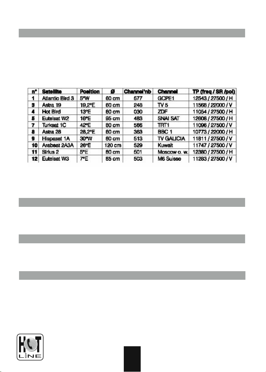
The level is always measured on a give channel. So, we will define, for
each satellite, a «reference channel» as the channel used to find this
satellite. The following table lists a set of reference channels. With time,
it is possible that one or more of these channels is no longer broadcast
or has its technical data change. If so, choose any other channel of the
satellite as a reference channel, provided that the Symbol Rate (SR) is
bigger than 22000.
6
0 208 994 1181
B
Necessary elements
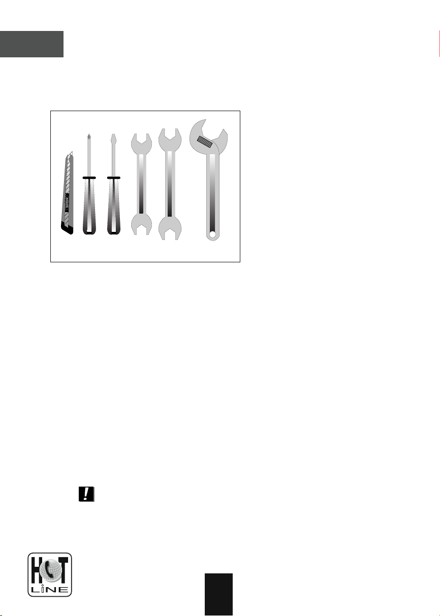
Necessary tools:
13
11
10
12
Note : for the motor itself, only a 13 mm spanner is necessary.
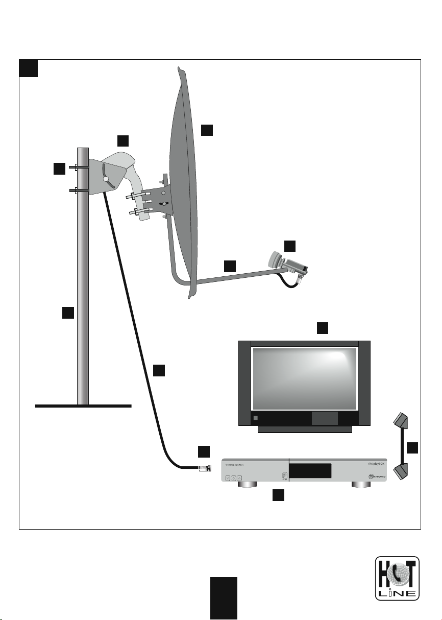
Elements:
1 Satellite dish
2 Screw and fixing
3 Offset arm
4 Universal LNB
5 Mast or stand off arm
Recommended diameter minimum: 40 mm (1,6’’)
6
Satellite receiver
7 TV set PAL for digital reception and PAL/SECAM for
analogue (to be able to watch it in colour)
8 Scart lead male/male 21 pin
9 «F» plug
10 Cable special for satellite,
(regular TV cable may not work)
11 Motor 450907
7
0 208 994 1181
1
1
11
2
4
3
5
7
10
9
6
8

8
0 208 994 1181
C
Prepare the motor (see diagram 2)
Assembling
• Make sure the fixing (tube or stand off arm) is stable and
strictly vertical. An error bigger than 1 degree (2 cm, or
3/4 inch per meter) from the vertical will preclude the
motor for working properly. If necessary, add some block
between the wall and the fixing. Check the verticality
with a spirit level or a plumb line.
• Assemble together the parts of the motor (diagram 2).
Put first the U-screws (1) through the part (2). While
assembling the part (2) with the body, pay attention to
the washer (3) : the part labelled «down» must be placed
on the bottom, as shown on the picture.
• Once the motor is assembled, do not fix it straight away
on the mast or the stand off arm, some operations needs
to be done near the receiver first.
 Loading...