

Page 1

P R O - S o f t Q A - 4 0 M / 4 5
U s e r M a n u a l
D e f i b r i l l a t o r - / T r a n s c u t a n e o u s
P a c e m a k e r A n a l y z e r
1
Page 2

Copyright 1997 by METRON. All rights reserved.
METRON:
USA _ FRANCE NORWAY
1345 Monroe NW, Suite 255A 30, rue Paul Claudel Travbaneveien 1
Grand Rapids, MI 49505 91000 Evry, France N-7044 Trondheim, Norway
Phone: (+1) 888 863-8766 Phone: (+33) 1 6078 8899 Phone: (+47) 7382 8500
Fax: (+1) 616 454-3350 Fax: (+33) 1 6078 6839 Fax: (+47) 7391 7009
E-mail: metronus@aol.com E-mail: metronfrance@infonie.fr E-mail: support@metron.no
License
By using the enclosed program and/or installing the files from the original disks to your hard drive, you are
agreeing to become bound by the terms of this agreement. If you do not agree to the terms of this agreement, return
all materials in this package to METRON U.S. within 30 days for a refund.
You have purchased a software license granting you the right to use the software contained herein. METRON
U.S. retains ownership of this software on the original disks, as well as any subsequent copies on any media or in
any form. METRON U.S. does not sell any rights to the software. METRON U.S. grants you the right to use the
software on the amount of computers for which you have purchased a License. If you wish to use this software for
more computers than you have Licenses, you must purchase additional Licenses from METRON U.S.
Your License to the program contained in the software grants you, the purchaser, permission to use the program for the purpose to which it was designed. The program files, in whole or in part, and all copyright or other
intellectual and proprietary rights therein are and remain the property of METRON U.S..
THIS SOFTWARE IS LICENSED ONLY TO YOU, THE LICENSEE, AND MAY NOT BE TRANSFERRED TO ANYONE WITHOUT THE WRITTEN CONSENT OF METRON U.S. Any authorized transferee
of the software shall be bound by the terms and conditions of this License. In no event may you transfer, assign,
rent, lease, sell, or otherwise dispose of the software on a temporary or permanent basis except as expressly provided herein.
This License is governed by the State of Michigan and shall benefit METRON U.S., its successors, and assigns. Licensee consents to jurisdiction in the state and federal courts located in the State of Michigan.
Limited Warranty/Disclaimer of Liability
METRON U.S. warrants that the software will substantially conform to published specifications and to the
documentation, provided that it is used on the computer hardware and with the operating system for which it was
designed. METRON U.S. will replace defective media or documentation, or correct substantial software errors at
no charge within 90 days of purchase. Contact METRON U.S. for information. If METRON U.S. is unable to correct the problem, the License fee will be refunded to you. These are your sole remedies for any breach of warranty.
BECAUSE SOFTWARE IS INHERENTLY COMPLEX AND MAY NOT BE COMPLETELY
FREE OF ERRORS, YOU ARE ADVISED TO VERIFY YOUR WORK. In no event will METRON
U.S. be liable for direct, indirect, special, incidental, or consequential damages arising out of the use
of or inability to use the software or documentation, even if advised of the possibility of such damages. METRON U.S. is not responsible for any costs, loss of profits, loss of data, or claims by third
parties due to use of, or inability to use the software.
Trademarks
IBM is a registered trademark, and PC/XT is a trademark of IBM Corporation. Microsoft is a registered trademark and Windows is a trademark of Microsoft Corporation.
2
Page 3

Table of Contents
MANUAL REVISION RECORD..........................................................................................................5
1. ABOUT PRO-SOFT QA-40M/45.......................................................................................................7
1.1 Introduction ..................................................................................................................................7
1.2 PRO-Soft QA-40M/45..................................................................................................................7
1.3 About your Manual.......................................................................................................................8
1.4 Updating PRO-Soft Program Files...............................................................................................8
2. GETTING STARTED..........................................................................................................................9
2.1 System Requirements....................................................................................................................9
2.2 Installing PRO-Soft .....................................................................................................................9
2.3 Initial Startup...............................................................................................................................10
2.4 Option Settings............................................................................................................................11
2.5 Printing Test Results...................................................................................................................14
3. TESTING SETUP...............................................................................................................................15
3.1 Equipment Setup.........................................................................................................................15
3.2 Power ..........................................................................................................................................15
3.3 Internal Paddles...........................................................................................................................16
3.4 Special Contacts..........................................................................................................................16
3.5 Initializing Remoting -Defibrillator Mode.................................................................................16
3.6 Initializing Remoting -Pacemaker Mode (QA-45 only)..........................................................17
4. MANUAL TESTING.........................................................................................................................18
4.1 Defibrillator Discharge (Energy) Test........................................................................................18
4.2 ECG Performance Test...............................................................................................................20
4.3 Shock Advisory Algorithm Test.................................................................................................22
4.4 Pacemaker Accuracy Test (QA-45 Only)...................................................................................23
4.5 Pacemaker Sensitivity Test (QA-45 Only).................................................................................24
4.6 Pacemaker Refractory Period Test (QA-45 Only) ....................................................................25
5. SEQUENCE TESTING.....................................................................................................................28
5.1 Sequence Form Window.............................................................................................................28
5.2 Defibrillator Test Sequence Setup..............................................................................................29
5.3 Pacemaker Test Sequence Setup................................................................................................30
5.4 Running a Sequence....................................................................................................................32
5.5 Sequence File Management........................................................................................................33
6. EMERGENCY SEQUENCE TRAINING.......................................................................................34
6.1 Sequence Setup...........................................................................................................................34
6.2 Running Emergency Sequences 1 - 7.........................................................................................35
6.3 Running Cardio Sequence...........................................................................................................36
7. SELECT CLOSE TO TERMINATE THE TEST AND RETURN TO THE MAIN SCREEN.
...................................................................................................................................................................36
3
Page 4

8. CHECKLISTS....................................................................................................................................37
8.1 Checklist Form Window.............................................................................................................37
8.2 Checklist Files Management ......................................................................................................37
9. PROTOCOLS.....................................................................................................................................39
9.1 Protocol Form Window...............................................................................................................39
9.2 Protocol Database........................................................................................................................41
9.3 Protocol File Management..........................................................................................................42
9.4 Importing Data ..........................................................................................................................43
10. TROUBLESHOOTING...................................................................................................................45
APPENDIX A: ERROR REPORT FORM, PRO-SOFT QA-40M/45...........................................47
APPENDIX B: SUGGESTION FORM, PRO-SOFT QA-40M/45.................................................49
4
Page 5

Manual Revision Record
This record page is for recording revisions to your PRO-Soft QA-40M/45 User Manual that have
been published by METRON or its authorized representatives. We recommend that only the management or facility representative authorized to process changes and revisions to publications:
• make the pen changes or insert the revised pages;
• ensure that obsolete pages are withdrawn and either disposed of immediately, or marked as
superseded and placed in a superseded document file, and;
• enter the information below reflecting that the revisions have been entered.
Rev No Date Entered Reason Signature of Person Entering Change
0 - Initial Release
5
Page 6

This page intentionally left blank.
6
Page 7

1.1 Introduction
1. About PRO-Soft QA-40M/45
The QA-40M and QA-45 Analyzers are precision instruments for
testing defibrillators and, additionally with the QA-45, transcutaneous pacemakers. They are designed to be used by trained technicians.
The defibrillator function of the QA-40M and QA-45 measures the
energy output, and ensures that the defibrillator complies with specified requirements. QA-40M and QA-45 have built-in load resistances of 50 ohms, which roughly correspond to the impedance of
the human body. The defibrillator pads are placed on the analyzers’
contact plates. Thus, the defibrillator is connected through the load
resistance. When the defibrillator is discharged, the analyzers calculate and display the energy delivered.
In the pacer function the QA-45 tests all types of transthoracic pacemakers. The testing is menu driven, and simple to operate. QA-45
measures and displays a pulse’s amplitude, rate, energy and width. It
also conducts demand sensitivity tests, measuring and displaying refractory periods, and immunity tests, which determine the pacemaker’s susceptibility to 50/60 Hz interference.
Testing with the QA-40M/45 is usually a matter of setting up the
preferred simulation parameters. Using PRO-Soft QA-40M/45 simplifies the process by providing an all Windows-based environment
through which simulation parameters are created by the user and
sent to the QA-40M/45 unit.
1.2 PRO-Soft QA-40M/45
PRO-Soft QA-40M/45 has two testing methods: manual or sequence. The manual method allows you to set up test parameters
quickly, and run one of the following stand alone tests. There are no
restrictions on the parameters used.
Defibrillator Discharge Test ECG Performance Test
Shock Advisory Algorithm Test Pacemaker Accuracy Test
Pacemaker Sensitivity Test Pacemaker Refractory Period Test
Test results are entered on the screen during testing. At the conclusion of testing the user may print a report, store the tests and results
on disk, or both.
Combinations of tests can be created and stored as “sequences.”
PRO-Soft QA-40M/45 maintains a library of these sequences. In this
way the user can store and retrieve sequences that are appropriate
for the kind of equipment being tested. Sequences can then be used
independently, or can be attached to a checklist, written procedure,
and equipment data in the form of a test “protocol.” The equipment
7
Page 8

1.3 About your Manual
data can be entered manually into the protocol, or it may be retrieved by PRO-Soft from the QA-MAP program, or other equipment files. Protocols with test results can be printed, or stored on
disk. Also, the results of testing can be sent to QA-MAP, or other
equipment maintenance management program, to close a work order
and update the defibrillator/transcutaneous pacemaker’s service history.
An additional feature of PRO-Soft QA-40M/45 is its ability to make
QA-40/45 serve as a training aid device for medical staff personnel
who operate defibrillators in the course of their duties. Several ECG
waveform emergency sequences are incorporated into the program.
These sequences interact with incoming defibrillator pulses, simulating various patient cardiovascular conditions.
This manual is designed to assist you in the basic procedures for creating test protocols with PRO-Soft QA-40M/45. It also covers all
features resident in the full PRO-Soft program. Familiarity with Microsoft Windows and its features is assumed. If you are unfamiliar
with it, we recommend that you use your Microsoft Windows User’s
Guide along with this manual.
This manual contains the following standardized text formatting
conventions:
This Represents
Bold title case Menu items and control buttons that can be selected
to perform operations. The underline ( _ ) represents
the shortcut key. For example, “Select File, Save” in-
structs you to press ”Alt+F,” then press “Alt+S.“ The
comma (,) between selections indicates that both selections are to be made in sequence.
< braces > Text information specified and entered by the user.
CAPITALS File names and paths. For example, “QAMDAT.50”
The menu under discussion
1.4 Updating PRO-Soft
Program Files
When installing upgrades,
backup or copy the original
program files to ensure that
data you desire to retain is
not overwritten.
NOTE
8
Occasionally, updated versions of PRO-Soft QA-40M/45 program
files are posted on METRON’s Web Site (http://www.metronbiomed. com). These can be downloaded through file transfer procedures. Registered users should contact their local METRON representative for more information regarding updating.
Page 9
2.1 System Requirements
2. Getting Started
The following are the minimum requirements for installation:
• IBM PC/XT-compatible machine, 80486 SX 25 MHZ or
higher.
• A 3.5" floppy drive.
• An EGA, VGA, 8514, Hercules or compatible display (rec-
ommended: VGA).
• 8 MB of RAM.
• 1 MB of unoccupied hard disk space, plus 3 MB of free
space on the drive contained the WINDOWS:\SYSTEM directory.
• Microsoft Windows version 3.11 or later version.
• Metron QA-40M/45.
• RS-232 cable (null modem/data transfer configured).
• Printer for reports. (MS-Windows compatible)
2.2 Installing PROSoft
1. Start Windows.
2. Insert PRO-Soft QA-40M/45 install disk # 1 into drive A
(or B).
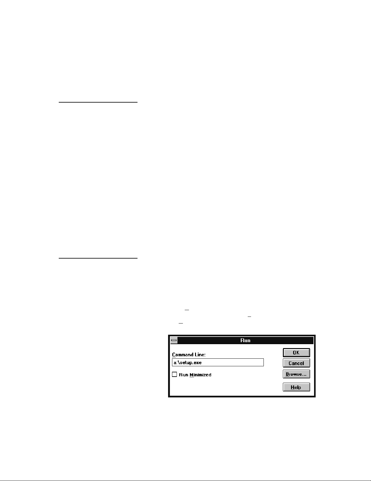
3. Select Run from the File Menu in the Windows Program
Manager. (In Win 95, click the Start button and then select Run.)
9
Page 10
If you are installing PROSoft QA-40M/45 for the
first time, we recommend
using the default drive,
directory, and program
group (C:\QA-40M/45)
4. Type <drive:\setup>. Then, click the OK button. If you
are installing PRO-Soft QA-40M/45 from a server or
shared directory, type the full path plus setup.
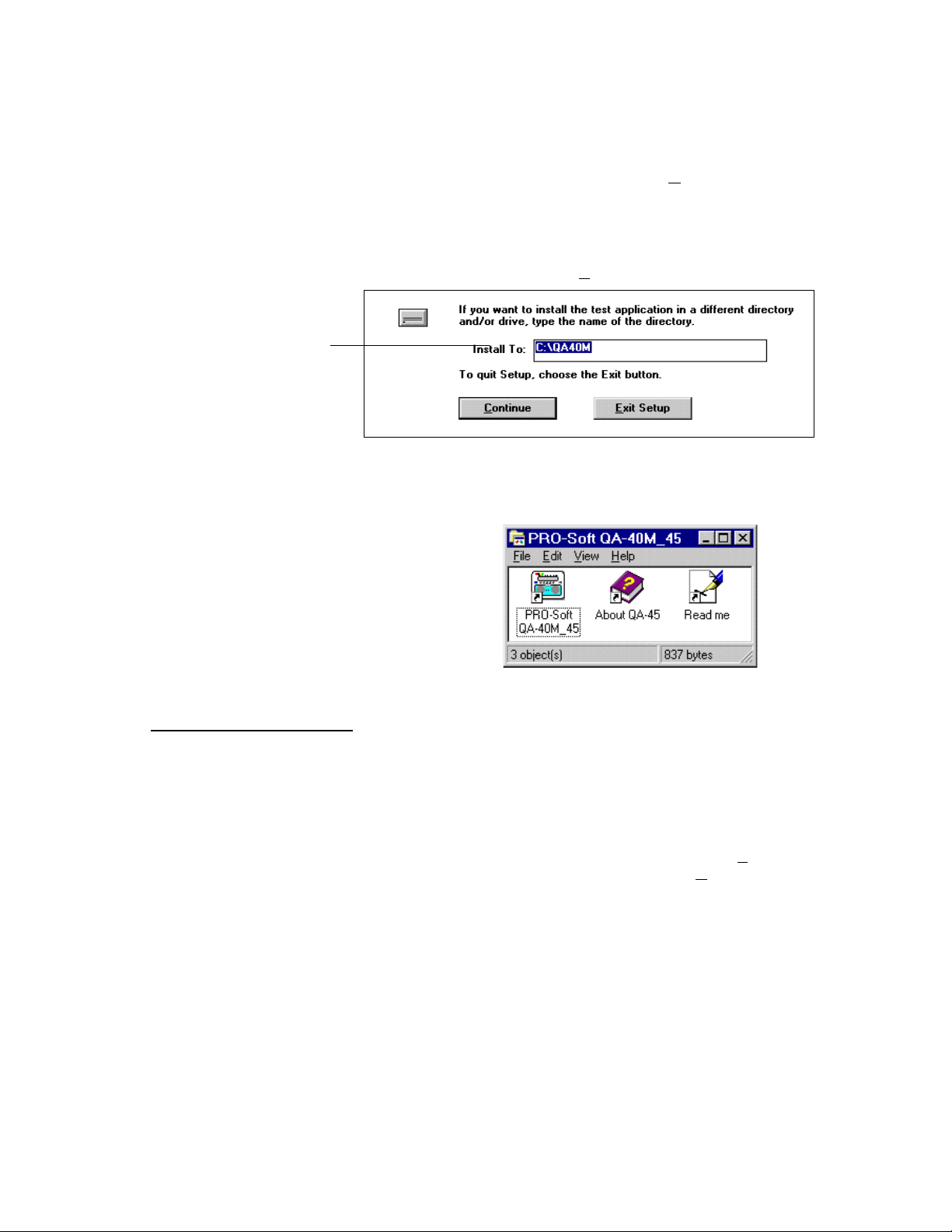
5. When setup starts, the following dialog box will appear.
Type in the desired drive and directory for PRO-Soft QA40M/45, then click the Continue button.
6. After setup is completed, a program group will be created in the Windows Program Manager called "PRO-Soft
QA-40M/45," or another name you provided during installation.
2.3 Initial Startup
7. Remove the last disk and store the install disks in a safe
place.
The first time that PRO-Soft QA-40M/45 is run, information has to
be entered, and the program configured for further use.
1. To start the program, double-click on the QA-40M/45
icon.
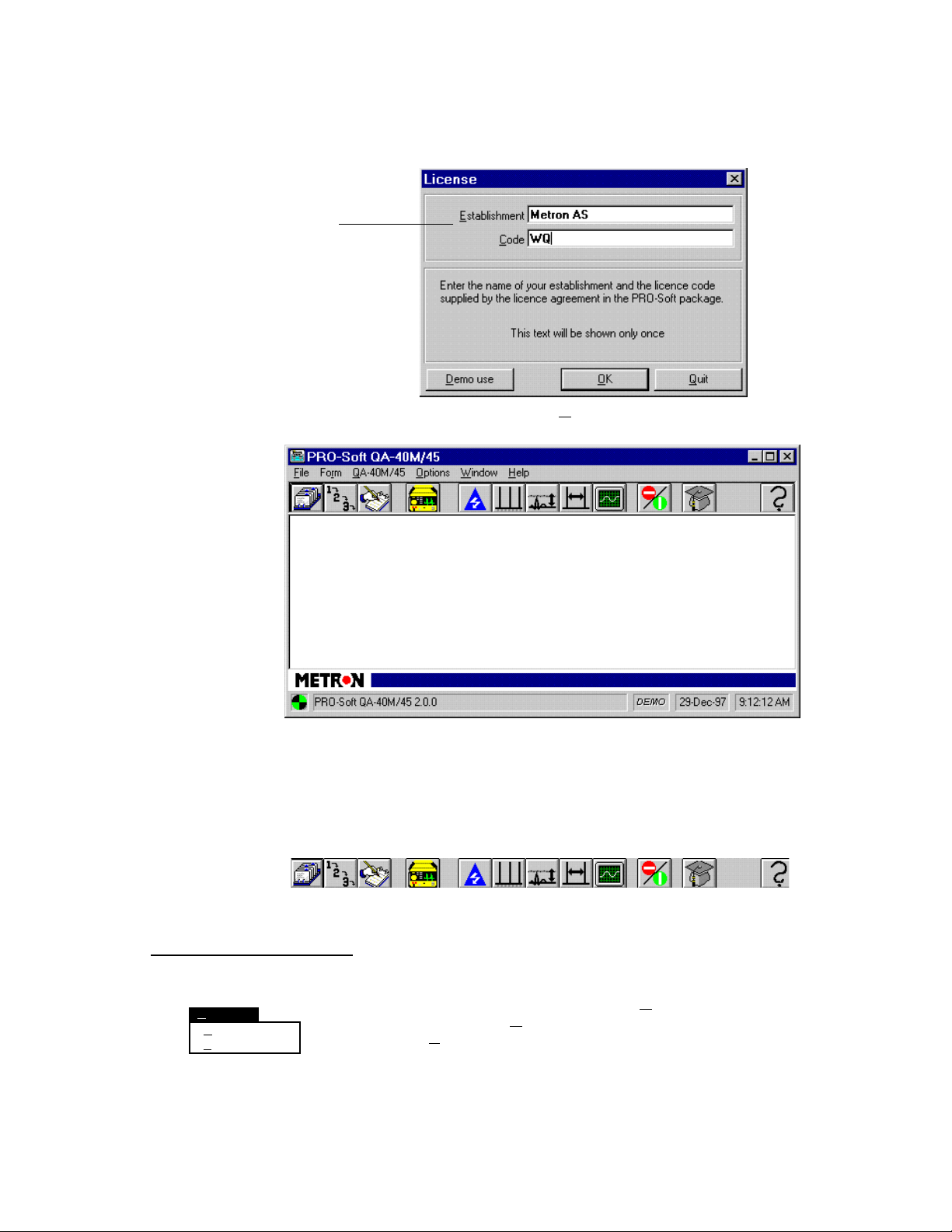
2. The following dialog box will appear. Enter the Estab-
lishment <license holder name>, and the Code <alphanumeric license number> exactly as written on the license
agreement supplied:
10
Page 11
Be careful to enter the name
and code exactly as written
on the license agreement.
3. When you click the OK button the PRO-Soft QA-40M/45
main application window is displayed:
Protocol Checklist
2.4 Option Settings
Options
General Ctl+G
Reports Ctl+R
The Main Application Window contains menus as well as
an icon bar. This bar enables the user to advance quickly
to the following program operations through pressing the
appropriate icon:
Defibrillator
Discharge
Test
Pacemaker
Sensitivity
Test
ECG
Performance
Test
Emergency
Sequence
Test
I I I I I I
I I I I I I
Sequence Equipment
Information
Pacemaker
Accuracy
Test
Pacemaker
Refractory
Period Test
Shock
Advisory
Algorithm Test
To configure program parameters click the Option Menu. Two further selections appear: General, which sets program pathing parameters, and Reports, which sets standardized report headers .
Help
11
Page 12
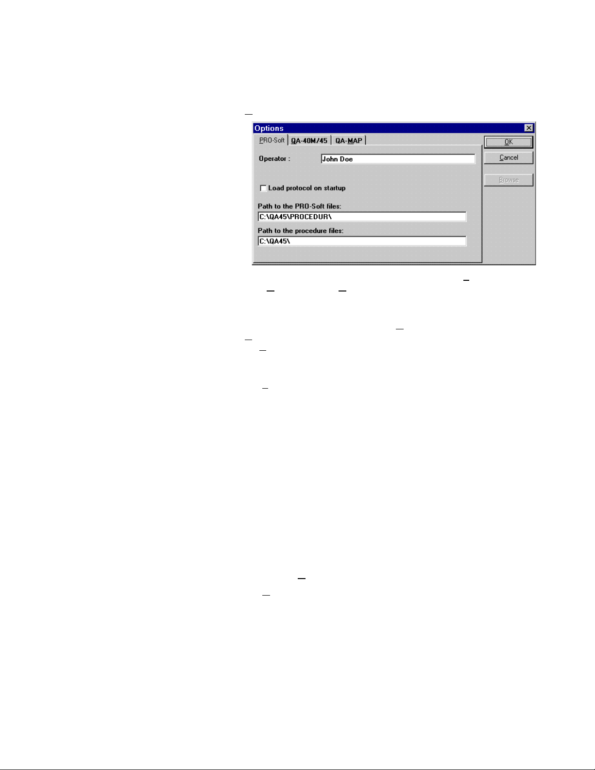
1. G eneral. When selected, the following dialog box appears:
In the topmost section of this box there are three tabs: PRO-
Soft, QA-40M/45, and QA-MAP. By clicking one of these
tabs, its corresponding card will be displayed, containing the
settings available for the item described on the tab.
After editing the option settings press OK to save changes, or
Cancel to discard them. When a <Path> text box is highlighted
the Browse button will also be available and, by pressing this
button, a file window will be displayed where you can select the
appropriate path.
a. P RO-Soft Tab. This tab provides basic identification of the
operator of the test equipment, as well as pathing directions
for the PRO-Soft program in order for it to function. The
configuration parameters and their descriptions are:
12
Operator: The person executing the tests.
Load protocol
at startup:
Path in the
PRO-Soft files: Path to the QA-40M/45 database files.
Path to procedure
files:
This option, when checked, automatically advances the program and opens
to a blank protocol window at startup.
Default path to the files where the test
procedures are stored.
The operator, automatic loading, and pathing settings, once
made, become the default settings. To change the defaults,
enter new operator and pathing settings or, in the case of
automatic protocol loading, uncheck the box. Then, save by
pressing OK.
b. Q A-40M/45 Tab. This tab is used to enter the serial num-
ber of the QA-40M/45 utilized for testing, and to set the
communications port (COM1-4) to be utilized for initiating
the QA-40M/45 remote setting at start-up. Once entered,
these become the default settings. To change the defaults,
Page 13
enter a new serial number or enter a new COM Port, and
save by pressing OK.
c. Q A-MAP Tab. Most QA-MAP interaction control settings
included in the PRO-Soft options may be changed during
the execution of the PRO-Soft QA-MAP Program1. However, the following default settings are only available
through the PRO-Soft QA-40M/45 options menu:
Path: Path to the QA-MAP file QAMDAT.MDB.
List equipment codes
when retrieving data:
Retrieve from QA-MAP:
- Equipment data
- Sequence
- Procedure
Controls whether the equipment list window
or the equipment code text box window
opens in the retrieval operation.
Sets the defaults as to the types of information extracted from QA-MAP.
Once entered, these become the default settings. To change
them, enter new setting and save by pressing OK.
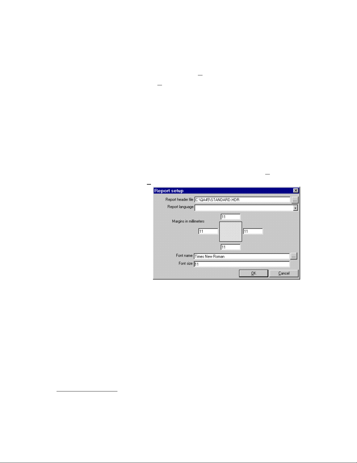
2. R eport. When selected, the following dialog box appears:
Report header title: The path and filename of the header to be
Report language: This text box is blank, as default is auto-
Margins in millimeters: Path to the QA-40M/45 database files.
Font name: Report default font.
Font size: Report default font size.
used on all reports.
matically English. If other languages are
desired, contact your METRON representative for the appropriate files.
The heading layout of test reports can be customized by
editing the file ‘STANDARD.HDR’ in the PRO-Soft directory with any text editor (e.g., MS Windows Notpad).
See Appendix A for further guidance.
1
Available separately from your Metron Representative.
13
Page 14
2.5 Printing Test Results
1. Test results are printed by selecting the Print button on the test
result window.
If this is the first test result for a manual test session you will be
prompted to fill in a Equipment Information Form (see below).
Each time a test is run thereafter, the printed result is buffered.
A complete report will be sent to the printer when the test window is closed.
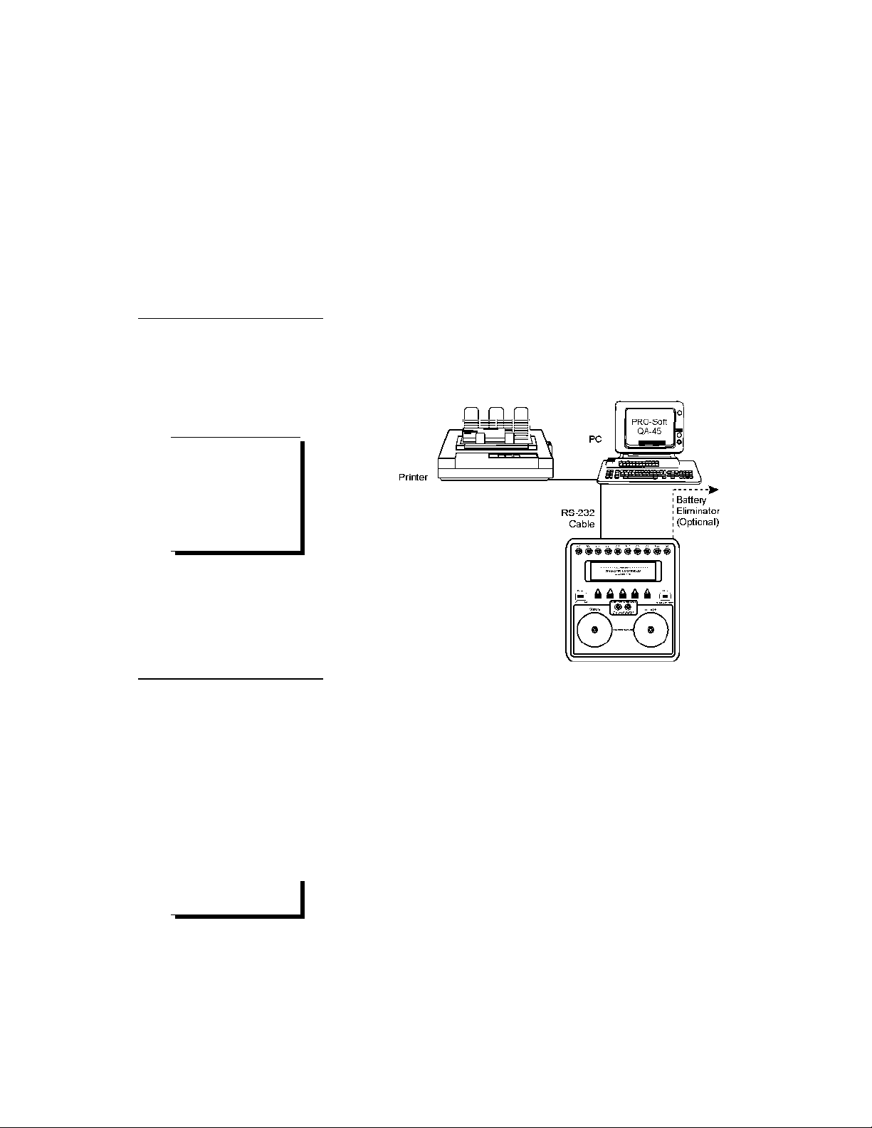
2. After selecting Print (or after entering the Equipment Information Form and selecting OK) the following window appears.
This is for prepublication review, and is in a WYSIWYG format.
14
Window controls enable you to enlarge the results, and navigate
from one page to the next. When review is complete, press the
Print button.
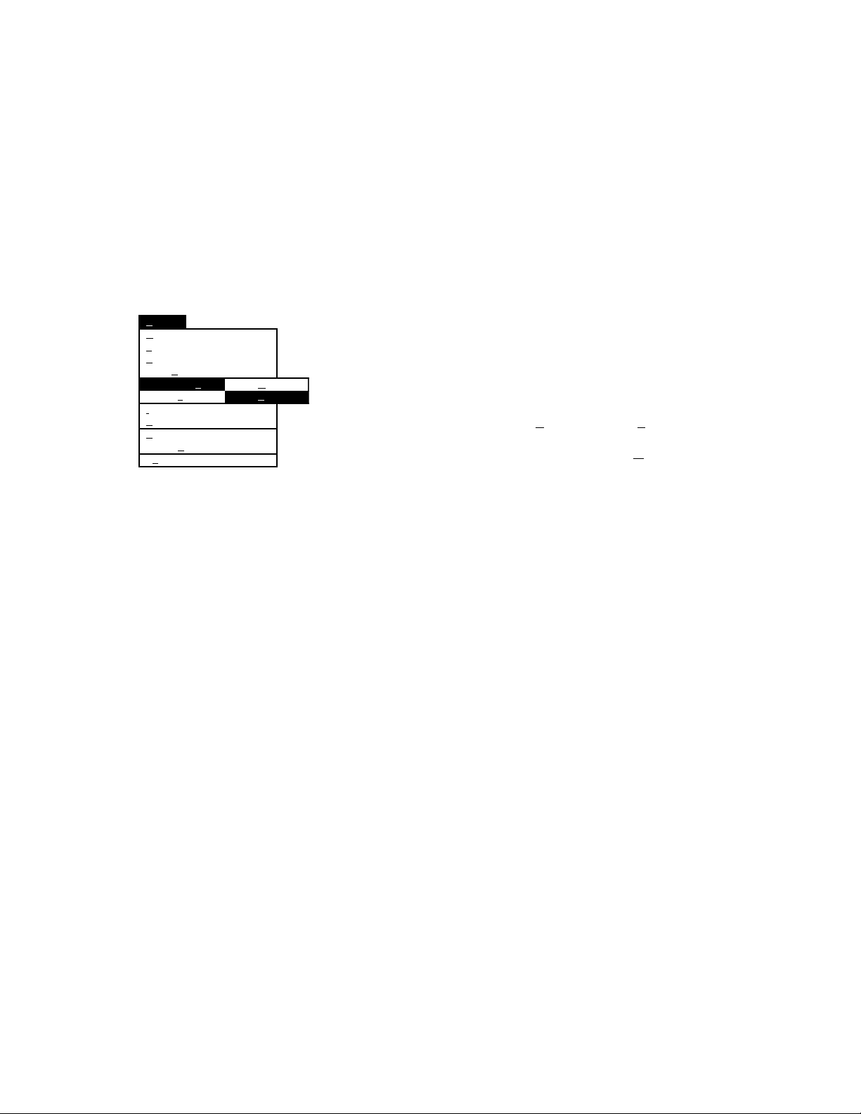
Page 15
3.1 Equipment Setup
3. Testing Setup
Communication between the PRO-Soft QA-40M/45 and the
QA-40M/45 is based upon an RS-232C interface, that is standard on
most modern personal computers. The operation is essentially a
“master-slave” configuration, whereby the computer operates the
QA-40M/45.
Attach an RS-232 (null modem/data transfer configured) cable to
the 9-pin D-sub outlet port located at the rear of the QA-45. Do not
attach the printer cable to the QA-45. See below.
Some RS-232C cables are
missing the connection between the seventh and the
eighth wires in the cable.
The cable may still be
called NULL-modem, but it
will not work with the
QA-40M/45.
3.2 Power
Do not use mercury, air or
carbon-zinc batteries.
NOTE
NOTE
1. Main On/Off Switch. QA-45 should remain off for at
least 5 seconds before switching on again, in order to allow the test circuits to discharge fully.
2. Low Battery Power. If battery power falls below 6.9
volts (± 0.3 volts), the display will show 'Change battery,
and reset system'. This means that the battery should either be replaced or the instrument should be connected to
a battery eliminator. The main switch has to be switched
off and then on again in order to use the instrument.
3. Changing Batteries. Open the compartments in the base
of the instrument, replace the old batteries with new ones,
and close the compartment covers. Use 9 volt alkaline
batteries (Duracell MN1604 or similar).
15
Page 16

NOTE
Remove the batteries and
disconnect the AC Adapter
if you do not intend to use
the QA-40M/45 for an extended period of time.
3.3 Internal Paddles
3.4 Special Contacts
4. Battery Eliminator
METRON’s AC Adapter plug-in power supply transformer allows you to use the QA-40M/45 anywhere a
standard electrical outlet is available. To attach the
adapter insert its small connector into the micro jack labeled “Batt. Elim. 9V DC” on the right rear of the unit.
Plug the large connector into a standard electrical outlet.
To be able to test defibrillators with internal paddles, an internal
paddle adapter has to be used. These contacts have a banana plug
that is attached to the standard paddle contact, and which is protected by a plastic insulation washer.
Certain defibrillators (automatic models and those with pacer options) have special contacts that are fastened to the electrodes attached to the patient. Metron AS has special accessory adapters to
suit the majority of these defibrillators. They are more or less the
same as the internal pad adapter except that they have a special
adapter on the top, which matches the contact on the defibrillator.
Defibrillator paddle adapter (specify defibrillator type): (P/N 13410)
Pacemaker external load cable (specify type pacemaker type): (P/N 13415)
3.5 Initializing Remoting Defibrillator Mode
1. Before initiating remote control, ensure that the:
• RS-232C cable is securely connected to the communication
ports on the QA-40M/45 and your computer.
• Proper communications port has been assigned.
• ‘Mode’ Switch is in the ‘HIGH’ or ‘LOW’ position.
High For Normal adult testing
Low For low energy testing, where energy does not exceed 50
joules, and peak voltage does not exceed 1200 volts.
• Low or high level ECG connectors are connected to the ten
4 mm AHA color-coded safety terminals, or standard phone
jack, as appropriate.
2. With the QA-40M/45 switched ON, advance to the Second
Main Menu Bar by pressing more-2 (F5):
16
Page 17

3.6 Initializing Remoting Pacemaker Mode
(QA-45 only)
Press REMOTE CONTR. (F4) to initiate remote control.
3. Communication will be established when testing or downloading of presets start. A rolling ball, located in the lower left corner of the main application window (see below), indicates that
communication between the computer and the QA-40M/45 is
active.
1. Before initiating remote control, ensure that the:
• RS-232C cable is securely connected to the communication
ports on the QA-40M/45 and your computer.
• Proper communications port has been assigned.
• Mode Switch is in the ‘PACE’ position.
• Pacemaker output cables are connected to either the 'Pacer
Input Variable Load' or 'Pacer Input Fixed Load' on QA-45.
• Pacemaker is in ‘DEMAND’ mode (if immunity testing).
2. With the QA-45 switched ON, advance to the Second Main
Menu Bar by pressing more-2 (F5):
Press REMOTE CONTR. (F4) to initiate remote control.
3. Communication will be established when testing or downloading of presets start. A rolling ball, located in the lower left corner of the main application window (see below), indicates that
communication between the computer and the QA-45 is active.
17
Page 18

4.1 Defibrillator Discharge (Energy) Test
4. Manual Testing
The Manual method allows you to set up test parameters quickly,
and run one of the following stand alone tests:
Defibrillator Discharge Test ECG Performance Test
Shock Advisory Algorithm Test Pacemaker Accuracy Test
Pacemaker Sensitivity Test Pacemaker Refractory Period Test
There are no restrictions on the parameters used. However, only the
QA-45 does both defibrillator and transcutaneous pacemaker testing.
The QA-40M is restricted to defibrillator testing only.
Manual tests can be activated in two ways. One is to select the appropriate icon from the icon menu bar in the Main Application Window. (The icons below are those which activate the tests.) The other
method is to select QA-45 from the PRO-Soft QA-40M/45 Main
Menu, and the Manual Test Menu appears. (See the menu below.)
Defibrillator
Discharge
Test
ECG
Perform.
Test
Shock Adv.
Algorithm
Test
1. General. QA-40M/45 measure the energy output, and ensure
that the defibrillator complies with specified requirements.
They have a built-in load resistance of 50 ohms, which roughly
corresponds to the impedance of the human body. The defibrillator pads are placed on the QA-40M/45 contact plates, thus ensuring that the defibrillator is connected through the load resistance. When the defibrillator is discharged, PRO-Soft calculates
and displays the energy delivered.
Defibrillator energy is defined as an integral of the moment of
the discharged energy from the defibrillator. The energy is
equal to the square of the voltage, divided by the load resistance.
E = p dt = V2 / R dt = V2 dt / R
Pacemaker
Accuracy
Test
Pacemaker
Sensitivity
Test
Pacemaker
Refractory
Period Test
QA-40M/45
Defibrillator discharge test
ECG performance test
Shock advisory algorithm test
Pacemaker accuracy test
Pacemaker sensitivity test
Pacemaker refractory period test
18
QA-40M/45 measures and records the voltage pulse every 100
µs, 1000 times, for a total time of 100 ms. The squares of the
voltages are then summed, multiplied by 100 µs, and divided by
the load resistance, 50 ohms.
1000 1000
E = (V
2
) • dt / R = (V2) • 100 µs / 50 ohms
2. Test Procedure.
a. Initiate remoting. (See chapter 3 for more information)
Page 19

b. Set the defibrillator to ‘SYNCHRONIZED’ mode, if
desired. If set, there must be an ECG wave and amplitude to simulate before testing begins. While the test
is activated, the waveform and amplitude cannot be
changed.
c. Press the Defibrillator Discharge Test icon button or se-
lect QA-45, Defibrillator discharge test from the PROSoft QA-40M/45 Main Menu, and the following appears.
d. In the Manual Energy Settings field, select the desired :
ECG Settings PRO-Soft QA-40M/45 includes the following
Amplitude 0.5, 1.0, 1.5 and 2.0 mV.
ECG wave selection for cardioversion tests, or
for the testing of ECG monitors:
Normal Sine Rates: 30, 60, 80, 120, 180, 240,
300 BPM.
ECG arrhythmia types are as follows:
Afib Atrial Fibrillation
2^BLKII Second degree A-V block
RBBB Right Bundle Branch Block
PAC Premature Atrial Contraction
PVC Early Early PVC
PVC Std PVC
PVC R on T R on T PVC
MF PVC Multifocal PVC
Bigeminy Bigeminy
Run of 5 PC Bigeminy Run of 5 PVCs
Vtach Ventricular Tachycardia
Vfib Ventricular Fibrillation
e. Click the Run button. PRO-Soft will set the ECG wave and
the amplitude and start waiting for a defibrillation. A defibrillation can then be fired until the Stop button is
pushed.
19
Page 20

If the Test Pulse button is activated while PRO-Soft is
waiting for a defibrillation, the QA-40M/45 will generate a
test pulse. The test pulse result will be shown in the form.
APEX (+) pad → right plate
STERNUM pad → left plate
4.2 ECG Performance Test
f. Securely place the defibrillator paddles on the QA-
40M/45 contact plates, and discharge the defibrillator. The
APEX (+) pad should be connected to the right-hand plate,
and the STERNUM pad to the left plate. This ensures correct signal polarity for the oscilloscope output. A reversal
of this configuration will not damage the QA-40M/45, nor
will it give incorrect energy readings. However, the polarity
of the oscilloscope output will simply be reversed. The discharge from the defibrillator is transferred to the QA40M/45's load resistance.
g. Following discharge PRO-Soft will display delivered en-
ergy, peak voltage, current, and synchronization delay in
the upper right portion of the Test Result field. After ten
seconds PRO-Soft also displays the discharge wave form in
the lower right portion of the Test Result field.
h. Before changing ECG wave or amplitude, click the Stop
button. Then enter setting changes.
i. Select Close to terminate testing and return to the Main
Screen. To print a report select the Print button.
1. General. The ECG Performance Test simulates the following
waves, and is designed for testing ECG monitors. Testing accu-
racy is ± 5 % (Lead II 1.0 mV).
Pulse: 1.0 mV Pulse lasts for 4 seconds. Used for testing
low frequency responses.
Square: 2 Hz 1.0 mV p-p biphasic. Used for testing amplifi-
cation and damping.
Triangle: 2 Hz 1.0 mV. Used for testing linearity.
Sinus: 0.1, 0.2, 0.5, 10, 40, 50, 60, and 100 Hz. Used for
testing frequency response.
Amplitude: 0.5, 1.0, 1.5, 2.0 mV (Lead II)
20
2. Test Procedure.
a. Initiate remoting. (See chapter 3.)
b. Set the defibrillator to ‘SYNCHRONIZED’ mode, if
desired. If set, there must be an ECG wave and amplitude to simulate before testing begins. While the test
is activated, the waveform and amplitude cannot be
changed.
c. Press the ECG Performance Test iicon button or se-
lect QA-45, ECG performance test from the PRO-
Page 21

APEX (+) pad → right plate
STERNUM pad → left plate
Soft QA-40M/45 Main Menu, and the following appears.
d. Select the desired ECG wave and Amplitude settings.
d. Click on the Run button. PRO-Soft runs the ECG per-
formance wave until the Stop button is selected.
d. Securely place the defibrillator paddles on the QA-
40M/45 contact plates, and discharge the defibrillator.
The APEX (+) pad should be connected to the righthand plate, and the STERNUM pad to the left plate.
This ensures correct signal polarity for the oscilloscope
output. A reversal of this configuration will not damage the QA-40M/45, nor will it give incorrect energy
readings. However, the polarity of the oscilloscope output will simply be reversed. The discharge from the defibrillator is transferred to the QA-40M/45's load resistance.
e. ECG performance waves can be run in sequence. By
selecting Autosequence, a mark will appear in the
checkbox. This mark tells you that if the Run button is
pushed, PRO-Soft will run the chosen ECG for ten seconds before jumping to the next one. All ECG waves
are performed in sequence.
If you do not want to wait ten seconds for the next wave,
the Advance button may be used. By selecting this button
the program will stop executing the active ECG wave and
start running the next on the list. To select the previous
wave in the list click the Back button.
f. Select Close to terminate testing and return to the Main
Screen. To print a report select the Print button.
21
Page 22

4.3 Shock Advisory Algorithm Test
1. General. This tests the analysis and prompting of certain defibrillators that can advise operators as to whether or not to perform a shock. PRO-Soft QA-40M/45 can simulate eight specific
waveforms for analysis by the defibrillator that should then
prompt the user to ‘shock’ or ‘no shock,’ in accordance with national and international guidelines. The waveforms are:
Asystolic: No ECG No shock
SVTa_90: Supraventricular tachycardia, 90 BPM No shock
PVT 140: Monoventricular tachycardia, 140 BPM No shock
MVT 140: Polyventricular tachycardia, 140 BPM No shock
PVT 160: Monoventricular tachycardia, 160 BPM Shock
MVT 160: Polyventricular tachycardia, 160 BPM Shock
CVF: Coarse Ventricular Fibrillation Shock
FVF: Fine Ventricular Fibrillation Shock
2. Test Procedure.
a. Initiate remoting. (See chapter 3 for more information)
b. Press the Shock Advisory Algorithm Test iicon button
or select QA-45, Shock advisory algorithm test from
the PRO-Soft QA-40M/45 Main Menu, and the following test window appears.
APEX (+) pad → right plate
STERNUM pad → left plate
22
c. Securely place the defibrillator paddles on the QA-
40M/45 contact plates, and discharge the defibrillator.
The APEX (+) pad should be connected to the righthand plate, and the STERNUM pad to the left plate.
This ensures correct signal polarity for the oscilloscope
output. A reversal of this configuration will not damage the QA-40M/45, nor will it give incorrect energy
readings. However, the polarity of the oscilloscope out-
Page 23

4.4 Pacemaker Accuracy Test (QA-45 Only)
put will be reversed. The discharge from the defibrillator is transferred to the QA-40M/45's load resistance.
d. Set the defibrillator to ‘SHOCK ADVISORY’ mode.
e. Run each of the curve forms for three or more seconds.
f. Check the appropriate check box if the defibrillator ad-
vised ‘shock’ or ‘not to shock.’
g. Select Close to terminate the test and return to the
Main Screen. To print a report select the Print button.
1. General. This test evaluates the pacer frequency and delivered
energy, and determines if noise interferes with the pacing. To
conduct it, the operator selects the following parameters:
Load: The load that will be applied between the pads.
The options are Pacer Input Fixed Load, or load
ranges of 50 to 2300 ohms. The latter are in steps
of 50 ohms up to 200 ohms, and 100 ohms from
200 up to 2300 ohms.
Noise: To simulate disturbances, 50 Hz, 1-10 mV or 60
Hz, 1-10 mV noise can be added
Rate set and limit: This specifies the target rate in ppm, and the ac-
cepted deviance in percent.
Amplitude set: This specifies the target amplitude in mA, and the
accepted deviance in percent.
2. Test Procedure.
a. If testing with noise, set pacemaker to ‘DEMAND’
mode.
b. Press the Pacemaker Accuracy Test iicon button or
select QA-45, Pacemaker accuracy test from the
PRO-Soft QA-40M/45 Main Menu, and the test setup
window appears.
c. Enter the desired settings.
d. Click on the Run button. The test result window then
appears (see below) displaying the rate, amplitude,
23
Page 24

pulse width and energy. For the rate and amplitude it
also shows the relative deviance (in percent) from the
target settings.
e. The result window continues to show the measure-
ments until you click the Close button. To print a report select the Print button. If you want to make a new
pacemaker accuracy test select the Next button to set
test parameters.
4.5 Pacemaker Sensitivity Test (QA-45 Only)
1. General. Sensitivity is the minimum QRS amplitude (mV) required to cause the pacemaker to operate in the ‘DEMAND’
mode. During sensitivity measurement three different waveforms are selectable, with widths varying in steps from 10 to
200 ms. This waveform is delayed from the pacer pulse so that
it is outside the pacing refractory period. PRO-Soft QA-45 then
checks whether this wave is sensed or not by the pacemaker.
If it is not sensed, a message 'EXCEEDED' is displayed, which
means that the pacemaker needs an amplitude of more than 100
mV for sensing at that setting. If the wave is sensed, PRO-Soft
then reduces the amplitude in steps until it reaches the lowest
value required for the pacemaker to sense it. (The internal algorithm used converges to the lowest value in the least number of
cycles.) This lowest value is the pace trigger sensitivity.
Parameters to this test are:
Load: The load that will be applied between the pads
Trigger wave: The waveform that will be used to trigger the
pacemaker. NOTE: A high pacer rate shortens
the length of the test
Limit pads: The maximum allowed threshold
Limit ECG: The maximum allowed threshold
24
Page 25

2. Test Procedure.
a. Press the Pacemaker Sensitivity Test iicon button or
select QA-45, Pacemaker sensitivity test from the
PRO-Soft QA-40M/45 Main Menu, and the test setup
window appears.
b. Enter the desired settings.
c. Click on the Run button. The test takes approximately
40 seconds with a pacemaker setting of 120 ppm.
b. The test result window then appears (see below) dis-
playing the Pads and ECG sensitivity in ms, and amplitude in mV.
4.6 Pacemaker Refractory Period Test (QA-45 Only)
c. The result window continues to show the measure-
ments until you click the Close button. To print a report select the Print button. If you want to make a new
pacemaker accuracy test select the Next button to set
test parameters.
1. General. This test is used to test the time interval in milliseconds during which the pacemaker is insensitive to any external
25
Page 26

inputs. PRO-Soft does this by measuring the maximum time interval after the generation of a pacer pulse, and maximum time
interval after a QRS wave.
a. Refractory Period. A time interval in milliseconds, during
which a pacemaker is insensitive to any external inputs. If a
QRS is detected during this period, the pacemaker ignores
it. On the other hand, if a QRS is detected outside the refractory interval, then the pacemaker resets its internal
timer and the next pacer pulse is generated after a delay of
one time period from this QRS wave.
b. Paced Refractory Period. The maximum time interval af-
ter the generation of a pacer pulse during which time the
presence of a QRS wave is ignored.
The measurement of paced refractory period takes a few
cycles of the pacemaker output. First, PRO-Soft measures
the pacer-to-pacer interval T. Then, it puts out a square
wave 40 milliseconds wide, delayed by delay time D,
which is more than the pacing refractory period, from the
last pacer pulse. The pacemaker senses this square wave.
The delay time D is gradually decremented in subsequent
cycles until the square waveform is not sensed by the pacemaker. The maximum value of the delay time D, for which
the pace maker does not sense the square wave, is the
paced refractory period.
c. Sensed Refractory Period. The maximum time interval
after a QRS wave is sensed by the pacemaker during which
time the presence of a second QRS wave is ignored.
The sensed refractory period is measured in a similar manner, except that PRO-Soft now generates two square waves
instead of one. The first square wave is generated at a fixed
time delay from a pacer pulse, which is greater than the
paced refractory period. The pacemaker always senses this
square wave.
The second square wave is generated at a delay D from the
first square wave. The initial value of D is selected to be
greater than the sensed refractory period. Therefore the first
time the pacemaker is on it also senses the second square
wave. In subsequent cycles, the delay 'D' is gradually reduced until the pacemaker is unable to sense the second
square wave. The maximum value of D, for which the
pacemaker does not sense the second square wave, is the
sensed refractory period. The purpose of the Pacemaker Refractory Period Test is to ensure that the pacer does not
give pulse when the heart is in the refractory state (T
wave).
26
Page 27

Parameters to this test are:
Load: The load that will be applied between
Rate set: The rate at which the pacemaker is set.
Paced refractory
period limit:
2. Test Procedure.
a. Press the Pacemaker Refractory Period Test iicon
button or select QA-45, Pacemaker refractory period
test from the PRO-Soft QA-40M/45 Main Menu, and
the test setup window appear.
the pads
NOTE: A high pacer rate shortens the
length of the test
Specifies the minimum paced refractory
period limit. NOTE: The limits are specified for each pacemaker, and depend
on the pulse rate that is set in the pacemaker.
b. Enter the desired settings.
c. Click on the Run button.
d. The test result window then appears (see below) dis-
playing the paced and sensed refractory periods in milliseconds.
e. The result window continues to show the measure-
ments until you click the Close button. To print a report select the Print button. If you want to make a new
pacemaker accuracy test select the Next button to set
test parameters.
27
Page 28

5.1 Sequence Form Window
5. Sequence Testing
Sequence testing enables the operator to perform multiple tests
semiautomatically. Instead of manually setting up and running one
test at a time, a sequence of several tests can be set up in advance of
testing. Once a sequence is created it can be it for later retrieval, and
reuse. There are no restrictions on how the sequence is composed.
Form
Sequence F2
Checklist F3
Protocol F4
Press the Sequenceiicon button from the icon menu bar, or select
Form, Sequence from the PRO-Soft QA- 40M/45 Main Menu. The
sequence window appears. The window contains six tabs. The Sequence info tab contains general information about the sequence,
and has three control buttons with which to activate the tabs.
Checking:
1. Defibrillator activates the tabs for:
• Defibrillator Discharge Test
• ECG Performance Test
2. External transcutaneous pacemaker activates the tabs for:
• Pacemaker Discharge (Accuracy) Test
• Pacemaker Sensitivity Test
• Pacemaker Refractory Period Test
3. Shock advisory algorithm activates the window for the Shock
Advisory Algorithm Test. (See Chapter 4)
28
Page 29

5.2 Defibrillator Test Sequence Setup
1. General. By clicking one of the defibrillator test tabs, the corresponding card will be displayed, containing a table for entering the settings to be incorporated in the testing.
2. Defibrillator Discharge Test. This tab provides a table for entering configuration parameters as follows:
Set Energy (J) Energy test value in joules
Limit (%) Limit value for delivered energy in percent.
NOTE: PRO-Soft allows to set illegal limit values
(i.e., less than)% or greater than 100%). Therefore, enter only values between 0 -100%.
Max. Delay (ms) If desired, the upper limit value for the delay, in
milliseconds
If an ECG wave with an amplitude is desired for each test click,
respectively, the ECG and Ampl fields. When the ECG field
is clicked, the following window appears. Only the presets
shown are available. Select the desired wave, then press OK.
The preset will then be entered in the ECG field in the test table.
When the Ampl field is clicked, the following window appears.
Select the desired amplitude, then press OK. The preset will
then be entered in the Ampl field in the test table.
29
Page 30

5.3 Pacemaker Test Sequence Setup
3. Defibrillator Charging Test. This tab provides a table for entering configuration parameters as follows:
Set Energy (J) Energy test value in joules
Limit (%) Limit value for delivered energy in percent.
NOTE: PRO-Soft allows to set illegal limit values
(i.e., less than)% or greater than 100%). Therefore, enter only values between 0 -100%.
Max. Delay (ms) If desired, the upper limit value for the delay, in
milliseconds
1. General. By clicking one of pacemaker test tabs, the corresponding card will be displayed, containing a table for entering
the settings to be incorporated in the testing.
2. Pace Discharge (Accuracy) Test. This tab provides a table for
entering the following configuration parameters:
Rate (ppm): Target rate in ppm.
Amplitude (mA): Target amplitude in mA.
Rate limit (%): Accepted deviance in percent.
Amplitude limit (%): Accepted deviance in percent.
Load: The load that will be applied between the pads.
The options are Pacer Input Fixed Load, or load
ranges of 50 to 2300 ohms. The latter are in
steps of 50 ohms up to 200 ohms, and 100 ohms
from 200 up to 2300 ohms.
Noise: To simulate disturbances, 50 Hz, 1-10 mV or 60
Hz, 1-10 mV noise can be added
When any field is clicked, the Pacemaker Accuracy Test Window appears.
30
Enter either the values into the text boxes, or select from the
drop down lists. When the desired values are entered, press
Run. The configuration is then transferred to the Pace Discharge test tab.
3. Sensitivity Test. This tab provides a table for entering the following configuration parameters:
Page 31

Limit pads (mV): The maximum allowed threshold in mV
Limit ECG (mV): The maximum allowed threshold in mV
Wave: The waveform that will be used to trigger the
Load: The load that will be applied between the pads
pacemaker. NOTE: A high pacer rate shortens
the length of the test
When any field is clicked, the Pacemaker sensitivity test parameters window appears.
Enter either the values into the text boxes, or select from the
drop down lists. When the desired values are entered, press
Run. The configuration is then transferred to the Sensitivity test
tab.
4. Refractory Period Test. This tab provides a table for entering
the following configuration parameters:
Pacer rate (ppm): The rate at which the pacemaker is set. NOTE:
Limit paced (ms): Minimum paced refractory period limit, in ms.
Limit sensed (ms): Minimum sensed refractory period limit, in ms.
A high pacer rate shortens the length of the test
NOTE: The limits are specified for each pacemaker, and depend on the pulse rate that is set
in the pacemaker.
NOTE: The limits are specified for each pacemaker, and depend on the pulse rate that is set
in the pacemaker.
When any field is clicked, the following manual pacemaker refractory period parameters window appears.
31
Page 32

5.4 Running a Sequence
Sequence
Add test
Remove test
Run test F11
Stop test F12
Enter either the values into the text boxes, or select from the
drop down lists. When the desired values are entered, press
Run. The configuration is then automatically entered in the sequence test tab.
After a test sequence has been defined and saved, it can be retrieved
and used at any time. To run a sequence test:
1. Load the test sequence desired by pressing the Sequenceiicon
button or selecting Form, Sequence, or Form, Protocol, View
Sequence from the PRO-Soft QA- 40M/45 Main Menu.
2. Select File, Load sequence. The Browse window opens, from
which the desired test sequence can be opened. Either doubleclick a file to open it, or highlight it and press the Open button.
3. From the Sequence Menu select Sequence, Run test. The sequence will then start running in the following order:
• Defibrillator Discharge Test
• Defibrillator Charging Test
• Pacemaker Discharge Test (QA-45 Only)
• Pacemaker Sensitivity Test (QA-45 Only)
• Pacemaker Refractory Period Test (QA-45 Only)
• Shock Advisory Algorithm Test (if selected)
4. In the Defibrillator Discharge Test, following discharge, PROSoft displays delivered energy, peak voltage, current, and synchronization delay for each test automatically. After ten seconds PRO-Soft also displays the discharge wave form in the
lower portion of the test tab.
32
5. When the Defibrillator Charging Test tab opens press the
Charge Timer (clock at the lower left of the tab). PRO-Soft
counts five seconds after test start, showing the following window, with a red background, during the countdown:
5
Wait until countdown reaches 0. Then
charge the defibrillator and fire.
When the countdown reaches zero, the window changes to
green, and the following message appears:
0
Charge the defibrillator
and fire immediately.
Press charge, and then press discharge until the pulse is given.
The test will then display the measured time from the end of
countdown until the pulse is given, as well as the resultant energy.
Page 33

5.5 Sequence File Management
File
New Sequence Ctl+N
Load Sequence Ctl+L
Save Sequence Ctl+S
Save Sequence As Ctl+A
Close Ctl+F4
Print
Printer Setup
Exit
1. N ew Sequence. Creates a blank sequence form. If an existing
sequence is in the form when this option is chosen, PRO-Soft
QA-40M/45 will prompt the user as to whether or not the current sequence is to be saved before clearing the form.
2. L oad Sequence. Opens the Browse form (see below) where a
previously saved sequence can be retrieved. This is done by
highlighting the sequence to be retrieved and pressing Open, or
double-clicking the desired sequence. If an existing sequence is
in the form when this option is chosen, PRO-Soft QA-40M/45
will prompt the user as to whether or not the current sequence is
to be saved before loading the next sequence.
Sequence
Add test
Remove test
Run test F11
Stop test F12
3. S ave Sequence and Save Sequence as. Saves the current se-
quence in the Sequence Database under the current or new file
name, as appropriate. By selecting the preferred storage format
both the sequence setup and the sequence result can be saved.
When saving test sequences the Browse form is opened, and
you must specify a sequence name.
4. Adding and Removing Tests. New tests are added by selecting
Sequence, Add test, or Sequence, Remove test.
5. P rint. To print a protocol, select File, Print. Then select
whether to print the protocol or write it to a file.
33
Page 34

6.1 Sequence Setup
6. Emergency Sequence Training
A unique feature of PRO-Soft QA-40M/45 is its ability to make
QA-40/45 serve as a training aid device for medical staff personnel
who operate defibrillators in the course of their duties. Several ECG
waveform emergency sequences are incorporated into the program.
These sequences interact with incoming defibrillator pulses, simulating various patient cardiovascular conditions.
Emergency sequences can be activated in two ways. One is to select
the Emergency Sequence Test icon button from the menu bar in the
Main Application Window. The other method is to select QA-45,
Emergency sequence test from the PRO-Soft QA-40M/45 Main
Menu. In doing either, the Emergency Sequence window opens:
34
1. Emergency Sequence. This field has seven emergency sequences, and one cardioversion sequence from which to select.
SEQUENCE PARAMETERS
Emergency 1 Starts with an 80 BPM normal sinus rhythm for 10
beats, a PVC (R on T), six normal beats, another
PVC (R on T) and then goes to a continuous Vfib.
Firing the defibrillator at any energy level will convert to normal ECG.
Emergency 2 Starts with 10 normal beats, then has 25 beats of
Vtach, and then also goes to a continuous Vfib. Firing the defibrillator at any energy level will convert
to normal ECG.
Emergency 3 Starts with Vfib. If a 200 Joule pulse is fired within
two minutes of starting, the waveform converts to
normal. Otherwise, the ECG will continue running
Page 35

6.2 Running Emergency Sequences 1 - 7
SEQUENCE PARAMETERS
Vfib.
Emergency 4 Same as Emergency 3, except that two pulses at
200 Joule are required within two minutes to convert to normal ECG.
Emergency 5 Same as Emergency 4, except that two pulses at
200 Joule followed by one pulse at 360 Joule are
required within two minutes to convert to normal
ECG.
Emergency 6 Same as Emergency 5, except that after converting
to normal and beating normally for three minutes,
the ECG shows two PVCs (R on T) and then reenters Vfib. The same series of two pulses at 200 J
and one at 360 J are required within two minutes to
convert to normal. Otherwise, the ECG will continue
running Vfib.
Emergency 7 ECG waveform starts at Vtach at 180 BPM for one
minute then goes to Vfib. Any defibrillator pulse
within two minutes will convert to normal. Otherwise, the ECG will continue running Vfib.
Cardio This sequence starts at continuous Atrial fibrillation.
The <<patient>> must be defibrillated synchronously to be successful.
2. Result. Following discharge PRO-Soft displays delivered energy in joules, peak voltage in volts, current in amps, and synchronization delay in milliseconds, in this field.
After a correct defibrillation,
the ECG may continue running Vfib for a short time before converting to normal.
This is not physiological, and
is due to the speed of the
communication between the
QA-40M/45 and the PC.
NOTE
1. Select one of the emergency sequences. Emergency sequences 3
through 6 require a certain energy of defibrillation, or sequence
of energies, to convert to a normal ECG waveform. In these sequences allowed variations must be specified. To do so, enter
the variation in the field labeled Energy Limit (%) (see illus-
tration).
2. Click on the Run button. PRO-Soft will then start executing this
sequence.
3. These sequences feature Vfib either immediately, or after running for a while. During execution, PRO-Soft displays text
showing the active ECG wave.
4. Whenever the sequence is in a Vfib state, the system waits for a
defibrillation. The measured energy, voltage, current and delay
will be displayed in the Result field.
5. When the Test pulse button is clicked, QA-40M/45 substitutes
the internal test pulse for an actual pulse, and assumes that the
pulse is the correct energy for the current sequence.
6. Before changing emergency sequences, or to cardio sequence,
click the Stop button.
35
Page 36

6.3 Running Cardio Sequence
7. Select Close to terminate the test and return to the Main Screen.
1. Select Cardio. When selected the following additional control
buttons appear in the window:
2. Click Run. PRO-Soft will then execute the sequence, starting at
continuous Afib. The <<patient>> must be defibrillated synchronously to be successful.
3. Fire a real synchronized defibrillator into the load, or click on
the Sync button to use a test pulse.
a. If the defibrillator pulse comes within 120 ms of the ECG
<<R>> wave, then the defibrillation is successful and the
wave will convert to a normal ECG.
b. If the defibrillator pulse is not synchronized within 120 ms,
or if the Late button for a Test pulse is pushed, the waveform will show the progress of Vfib. The <<patient>> is
then in an emergency condition, and a 200 joule pulse is required to convert the waveform to normal.
4. Before changing to an emergency sequence, click the Stop button.
7. Select Close to terminate the test and return to the Main Screen.
36
Page 37

8.1 Checklist Form Window
FormSequenceF2
klistF3
ProtocolF4
8. Checklists
The checklist adds manually or visually performed tests and function checks to the protocols (see Chapter 8). Once created, a checklist can be edited, stored and retrieved for future use.
Press the Checklist icon button from the icon menu bar, or select
Form, Checklist from the PRO-Soft QA-40M/45 Main Menu and
Chec
the Checklist form appears (see below). It is a table allowing for up
to 30 lines, where each line contains a description of what to examine (up to 50 characters). Each line also has two check boxes, 'OK'
and 'Failed,' to be used when examining the defibrillator or transcutaneous pacemaker.
Checklist
Add item
Remove item
8.2 Checklist Files Management
File
New Ctl+N
Load... Ctl+L
Save... Ctl+S
Save As... Ctl+A
Delete...
Print... Ctl+P
Printer setup
Exit
To enter text, or edit text highlight the field you want to edit with
the mouse, and then enter the text. After entering the desired text either press to confirm the new or changed text, or to discard it.
Another method is to select Checklist, then either Add item to create a new checklist item, or Remove item to discard it.
In order to update the check boxes the checklist must be connected
to a protocol and edited through this protocol (see the protocols con-
nected checklist in the section Protocol).
1. New Checklist. Select File, New. The current checklist window
clears and initializes a new checklist form. If you already have
an active checklist containing unsaved changes, a dialog box
appears. It prompts you as to whether or not you want to save
37
Page 38

the changes, discard them, or abort the operation and return to
the active checklist.
2. Loading and Saving Checklists. To save the active checklist,
select File, Save or File, Save As. A Save As window will open
(see below), prompting for a name to use for the checklist. After
the name has been entered in File name, press OK.
To retrieve an existing checklist, select File, Load. A Browse
window opens (see below). Select among the available checklists and double click it, or highlight it and press Open.
38
3. Printing Checklists. To print a checklist, select File, Print.
Then, select whether to print the checklist, or write it to a file.
Page 39

9.1 Protocol Form Window
9. Protocols
Protocol contains a description of the defibrillator or transcutaneous
pacemaker being tested, and specifies an associated test sequence
and checklist. It also includes a procedure file, stating special concerns for each defibrillator or pacemaker.
When saved, the results are added to PRO-Soft 40M/45’s protocol
database, or to QA-MAP, if installed. This database is an historical
record of those protocols for which safety tests have been done with
PRO-Soft. Information stored includes the:
• Tested defibrillator or pacemaker’s identifying information.
• Test sequence used in the test
• Date the safety test was executed
• Status of the test (OK, Failed)
• Protocol filename containing the test results.
Form
Sequence F2
Checklist F3
Protocol F4
Press the Protocol icon button from the icon menu bar, or select
Form, Protocol from the PRO-Soft QA-40M/45 Main Menu and the
Protocol form appears (see below).
39
Page 40

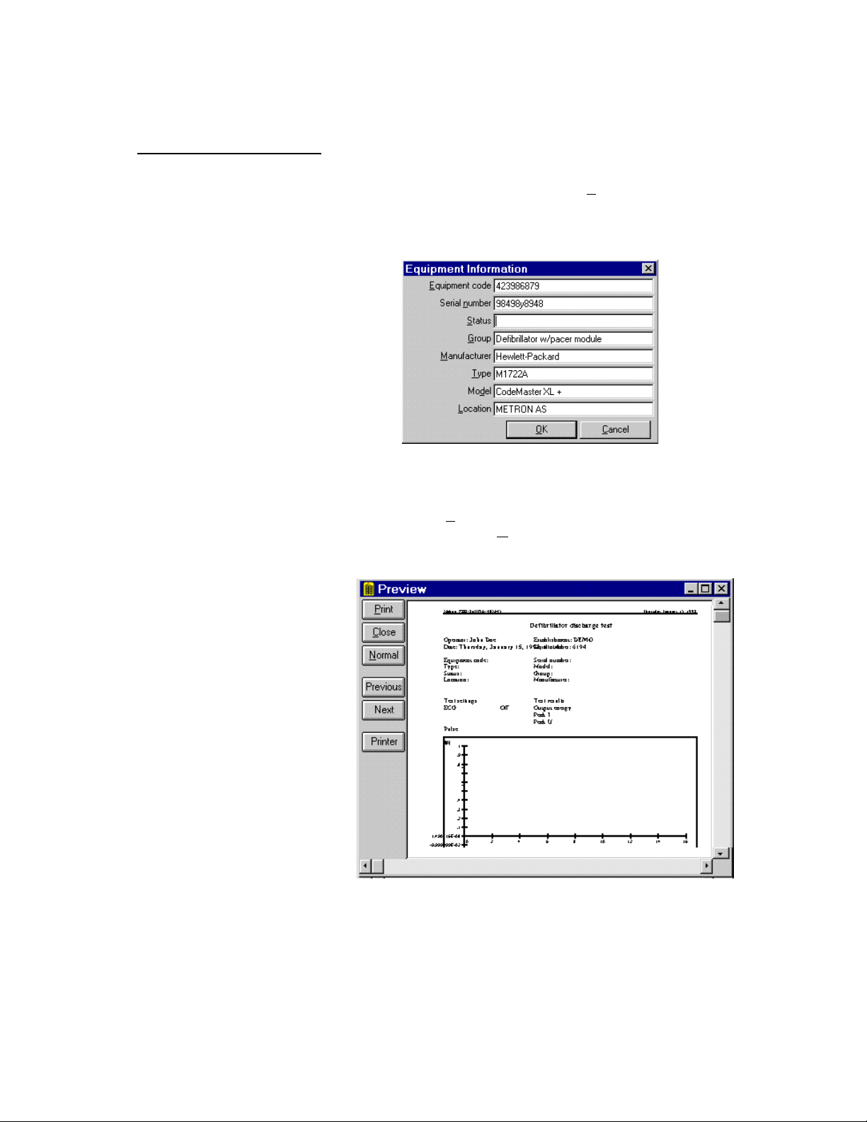
The Protocol application window contains the following fields:
1. E quipment Information Field. This field contains text boxes
that are used to describe the defibrillator or transcutaneous
pacemaker under test, and are also used in the safety testing report to document the test of a particular defibrillator or transcutaneous pacemaker. The text boxes, each containing space for
up to 30 characters, are:
Equipment code: The equipment identifier
Serial number: The equipment serial number
Status: The equipment status
Group: The equipment group
Manufacturer: Manufacturer of the equipment on test
Type: The equipment type
Model: The equipment model
Location: Location of the equipment on test
PRO-Soft can load equipment information already entered in an
ASCII text file or, if you have PRO-Soft QA-MAP installed,
from that program. See paragraph 8.4.
2. R emark Field. This field is for inserting remarks on the test.
The remark may contain up to 300 characters long, describing
special events that may have occurred during the testing. Any
testing anomalies peculiar to the equipment under test, or on the
testing itself, should be entered in this box.
File
New protocol Ctl+N
Load Ctl+L
Save Ctl+S
Save As Ctl+A
Equipment data
Procedure Load
Import Save
Export Save As
Print
Printer Setup
Exit
Protocol
View sequence
View checklist
Run test F11
Stop test F12
3. P rocedure Field. This field is for detailing the testing proce-
dure used. For example, it can be a description of how to connect the QA-40M/45 to the instrument under test. Procedure is
always saved to a separate text file (*.txt). It can be created and
edited by typing the information in the procedure text box or,
by using any text editor/word processor capable of saving plain
text files (e.g., Windows Notepad). When you select an item in
File, Procedure, a dialog box appears where you can specify
the file you need by its filename. The title of the dialog box
shown depends on whether you select Load, Save or Save As.
If you have already saved the procedure, Save will store your
changes under the filename you specified the first time you
saved the file, while Save As will prompt you for a new filename.
4. Sequence and Checklist Fields. These drop down list boxes
contain listings of all sequences and checklists resident in their
respective databases. Select which of them PRO-Soft will use to
test the equipment described in your protocol. When you have
selected a sequence and checklist the menu items Protocol,
View sequence and Protocol, View checklist become available. When selecting either of these menu items PRO-Soft will
load the sequence or checklist and switch to the respective application window, where you may edit it before running the test.
If you already have an active sequence or checklist, containing
40
Page 41

9.2 Protocol Database
unsaved changes, a dialog box appears, giving you an opportunity to save the changes.
When first opening the protocol application window with a new
protocol these fields will be blank, indicating that no sequence
or checklist is connected to the protocol. They have to be created and connected to the protocol before they will appear.
Protocols are saved and retrieved from the Protocol Database (see
below). This database is an historical record of those protocols for
which safety tests have been done with PRO-Soft. The information
stored includes the:
• Tested defibrillator or transcutaneous pacemaker’s equipment
code and serial number
• Test sequence used in the test
• Date the safety test was executed
• Status of the test (OK, Failed)
• Protocol filename containing the test results.
To access the protocol database the Protocol format must be open.
To do so press the Protocol icon button from the icon menu bar, or
select Form, Protocol from the PRO-Soft QA-40M/45 Main Menu.
Then, select File, Load. The following dialog box appears:
The Browse window contains two fields.
1. Identification/Test Time/File name. These list boxes contain
the protocols already added to the database by equipment serial
number, test time and file name.
2. Control. This field manages the database.
a. Open loads the selected protocol into the active protocol
window, allowing you to view the safety test results and
41
Page 42

other information stored in the protocol. If you already
have a protocol open in the active window, and this protocol contains unsaved changes, PRO-Soft will not load the
protocol selected in the database until you have responded
to a dialog box prompting you to save the open protocol.
b. Delete removes selected protocol(s) from the library,
prompting for confirmation. Clicking No prevents deletion.
If more than one for deletion is selected, PRO-Soft will
leave the current equipment and continue to the next one
selected, and display the message for this one.
c. Cancel interrupts the entire delete operation. Note that
equipment protocols deleted before selecting Cancel (or
No) will not be restored.
d. Update QA-MAP is designed specifically to update
METRON’s QA-MAP. For this to operate QA-MAP must
be installed, and the QA-MAP tab in Options, Edit Op-
tions must be configured accordingly (see Chapter 2).
When this button is clicked, PRO-Soft updates QA-MAP’s
Test table with the status of all test results added to the protocol database since the last update operation. Included in
the update is the:
• Tested defibrillator or pacemaker’s equipment code and
serial number
• Test sequence used in the test
9.3 Protocol File Management
File
New protocol Ctl+N
Load Ctl+L
Save Ctl+S
Save As Ctl+A
Equipment data
Procedure
Import
Export
Print
Printer Setup
Exit
• Date the safety test was executed
• Status of the test (OK, Failed)
• PRO-Soft program executing the update (i.e., PRO-Soft
QA-40M/45)
1. New Protocol. Select File, New protocol. The system will display an empty Protocol Form window. Fill in the required information and select the test sequence and checklist to use with the
defibrillator or transcutaneous pacemaker being tested.
You can open multiple protocols to allow you to compare, for ex-
ample, this year’s and last year’s test results. To do so select
Form, Protocol, and then open another protocol window by selecting File, New Protocol. Then, select Window, Tile Hori-
zontal, so that both forms appear together. To compare the test
results load the protocol corresponding to this year’s testing into
one of the protocol windows, and the protocol corresponding
the last year’s testing into the other window.
2. Saving Protocols. Protocols are saved to the Protocol Data-
base. To save the active protocol, select File, Save or File,
42
Page 43

9.4 Importing Data
File
New protocol Ctl+N
Load Ctl+L
Save Ctl+S
Save As Ctl+A
Equipment data From QA-MAP
Procedure From ASCII-file
Import
Export
Print
Printer Setup
Exit
Save As. The Protocol Database window will open, and you
will then be prompted for a name to use for the protocol.
3. Retrieving Protocols. Select File, Load, and the Browse window is opened. Select among the available protocols the one
that is desired, and double click to load it into the protocol window.
4. Printing Protocols. To print a protocol, select File, Print.
Then, select whether to print the protocol or write it to a file.
Equipment files pertaining to defibrillator or transcutaneous pacemakers in the inventory can be created from ASCII text files, or can
be imported into PRO-Soft QA-40M/45 from METRON’s QA-MAP
program. This appendix details the procedures for these options.
1. Retrieving from QA-MAP. Data on the defibrillator or transcutaneous pacemaker to be tested can be imported directly
from METRON’s QA-MAP. For this feature to operate QAMAP must be installed, and the QA-MAP tab in Options, Edit
Options must be configured to reflect Retrieve Appliance
Data. (cf. Paragraph 2.2.2).
To import the data select File, Equipment data, From QA-MAP
in the Main Menu.. When the following dialogue box appears,
select the appliance code for the defibrillator or transcutaneous
pacemaker you wish to test and click on OK. Information
stored in QA-MAP states which test sequence to use for each
defibrillator or transcutaneous pacemaker.
2. Making Protocol Formats from an ASCII Text File. PROSoft can load equipment information from an ASCII text file.
ASCII text files can be created on each of the defibrillator or
transcutaneous pacemakers for which you intend to produce
protocol formats. The ASCII file must follow this pattern :
43
Page 44
EquipCode = <Equipment Code>
SerNo = <Serial Number>
Status = <Status>
Group = <Group>
Manufacturer = <Manufacturer>
Model = <Model>
Type = <Type>
Location = <Location>
Sequence Name = <Name of Test Sequence>
Procedure = <Procedure Filename>
File
New protocol Ctl+N
Load Ctl+L
Save Ctl+S
Save As Ctl+A
Equipment data From QA-MAP
Procedure From ASCII-file
Import
Export
Print
Printer Setup
Exit
This file contains information on one defibrillator or transcuta-
neous pacemaker. The text preceding the '=' sign is only for
your convenience. The text following the '=' sign is used to construct a protocol format. Make sure that the lines appear in the
right order, i.e., appliance code first, .... , procedure text last.
Use a text editor or a word processor that can save ASCII text
to create the file (e.g., Notepad). To produce protocol formats
from the data in the file, select File, Equipment data, From
ASCII-file. Select the file containing the defibrillator or transcutaneous pacemaker information and click on OK. The program will read the file and add one new protocol format to the
database library for each defibrillator or transcutaneous pacemaker
44
Page 45

10. Troubleshooting
Problem Possible Solution
Test sequence grid
will not accept data
Check the tests to be made in the 'Tests' frame.
Reports are not printed
Strange characters appear in a report
Ball does not rotate when remoting
is attempted, or is set.
Messages:
‘The port is already taken (8005)’
‘Error in Send Command at line 0. Operator
valid only when port is open (8018).’
1. Wrong printer driver. Choose the correct printer
when running print report.
2. Do not check the print to file box when running
print report.
Wrong printer driver. Choose the appropriate printer in
the Print Manager program.
Communications are not established between the
computer and the QA-IDS. Check to ensure that:
1. The QA-IDS is set to “Remote Control.”
2. The correct COM-Port is assigned in the
Options Menu.
3. The RS-232 cable has a null modem/data trans-
fer configuration.
45
Page 46

This page intentionally left blank.
46
Page 47

APPENDIX A: ERROR REPORT FORM, PRO-SOFT
QA-40M/45
PRO-SOFT QA-40M/45 ERROR REPORT FORM
USA _ FRANCE NORWAY
1345 Monroe NW, Suite 255A 30, rue Paul Claudel Travbaneveien 1
Grand Rapids, MI 49505 91000 Evry, France N-7044 Trondheim, Norway
Phone: (+1) 888 863-8766 Phone: (+33) 1 6078 8899 Phone: (+47) 7382 8500
Fax: (+1) 616 454-3350 Fax: (+33) 1 6078 6839 Fax: (+47) 7391 7009
E-mail: metronus@aol.com E-mail: metronfrance@infonie.fr E-mail: support@metron.no
From: (name) Phone:
Address: Fax:
Date:
PRO-Soft QA-40M/45 Error Report Product:
Version:
Type
チ Wrong results チ Error messages, without reason
チ Program stops, no reaction チ Wrong responses on commands.
チ Other
Description of the situation prior to the error:
Description of the error:
(METRON use internally)
Received date: Comments:
Correction date:
Ref No.
チ Critical
チ Minor
チ Normal
47
Page 48

This page intentionally left blank.
48
Page 49

APPENDIX B: SUGGESTION FORM, PRO-SOFT QA-
40M/45
PRO-SOFT QA-40M/45 SUGGESTION FORM
USA _ FRANCE NORWAY
1345 Monroe NW, Suite 255A 30, rue Paul Claudel Travbaneveien 1
Grand Rapids, MI 49505 91000 Evry, France N-7044 Trondheim, Norway
Phone: (+1) 888 863-8766 Phone: (+33) 1 6078 8899 Phone: (+47) 7382 8500
Fax: (+1) 616 454-3350 Fax: (+33) 1 6078 6839 Fax: (+47) 7391 7009
E-mail: metronus@aol.com E-mail: metronfrance@infonie.fr E-mail: support@metron.no
From: (name) Phone:
Address: Fax:
Date:
PRO-Soft QA-40M/45 Improvement Suggestion Product:
Version:
Type
チ One window チ Presentation
チ Several windows チ Options, configuration possibilities
チ Documentation チ Other
Description of the suggested improvement:
(METRON use internally)
Received date: Comments:
Correction date:
Ref No.
49
Page 50

This page intentionally left blank.
50
Page 51

51
 Loading...