

Page 1
QA-1290
User & Service Manual
1.66 Firmware and higher.
QA-1290 NIBP-Analyzer
P/N 17525
V.1.66
Page 2

Copyright 2003 by METRON. All rights reserved.
METRON:
http://www.metron-biomed.com/
USA FRANCE GERMANY NORWAY
1345 Monroe NW, Suite 255A 30, rue Paul Claudel Römerstrasse 22 Vegamot 8
Grand Rapids, MI 49505 F-91000 Evry D-63741 Aschaffenburg N-7048 Trondheim
Phone: (+1) 888 863-8766 Phone: (+33) 1 6078 8899 Phone: (+49) 6021 447 9807 Phone: (+47) 7395 4700
Fax: (+1) 616 454-3350 Fax: (+33) 1 6078 6839 Fax: (+49) 6021 447 9808 Fax: (+47) 7395 4701
E-mail: support.us@metron-biomed.com E-mail: info@metron.fr E-mail: proteges@t-online.de
E-mail: support@metron.no
Disclaimer
METRON provides this publication as is without warranty of any kind, either express or implied,
including but not limited to the implied warranties of merchantability or fitness for any particular purpose. Further, METRON reserves the right to revise this publication and to make changes from time to
time to the content hereof, without obligation to METRON or its local representatives to notify any
person of such revision or changes. Some jurisdictions do not allow disclaimers of expressed or implied
warranties in certain transactions; therefore, this statement may not apply to you.
Limited Warranty
METRON warrants that the QA-1290 NIBP Analyzer will substantially conform to published specifications and to the documentation, provided that it is used for the purpose for which it was designed.
METRON will, for a period of twelve (12) months from date of purchase, replace or repair any defective
analyzer, if the fault is due to a manufacturing defect. In no event will METRON or its local representatives be liable for direct, indirect, special, incidental, or consequential damages arising out of the use of
or inability to use the QA-1290 NIBP Analyzer, even if advised of the possibility of such damages.
METRON or its local representatives are not responsible for any costs, loss of profits, loss of data, or
claims by third parties due to use of, or inability to use the QA-1290 NIBP Analyzer. Neither METRON
nor its local representatives will accept, nor be bound by any other form of guarantee concerning the
QA-1290 NIBP Analyzer other than this guarantee. Some jurisdictions do not allow disclaimers of expressed or implied warranties in certain transactions; therefore, this statement may not apply to you.
ii
Page 3

Table of Contents
1. INTRODUCTION ....................................................................................................................... 1-1
1.1 Features.............................................................................................................................. 1-1
1.2 Specifications..................................................................................................................... 1-2
1.3 General Information........................................................................................................... 1-3
2. INSTALLATION......................................................................................................................... 2-1
2.1 Receipt, Inspection and Return.......................................................................................... 2-1
2.2 Setup .................................................................................................................................. 2-2
2.3 Connecting the Device under Test..................................................................................... 2-2
2.4 Ansur plug in QA-1290 ..................................................................................................... 2-4
3. OPERATING QA-1290...............................................................................................................3-1
3.1 Control Switches and Connections.................................................................................... 3-1
3.2 QA-1290’s Controls .......................................................................................................... 3-2
3.3 QA-1290 Startup................................................................................................................ 3-3
3.4 QA-1290 Main Menu ........................................................................................................ 3-3
3.5 Configuring QA-1290........................................................................................................ 3-4
3.6 Printing Results.................................................................................................................. 3-6
3.7 Upgrading QA-1290 Firmware......................................................................................... 3-7
4. BLOOD PRESSURE TESTING ................................................................................................ 4-1
4.1 Measuring Cuff Volume.................................................................................................... 4-1
4.2 Setting Test Parameters ..................................................................................................... 4-2
4.3 Running BP Tests .............................................................................................................. 4-6
5. LEAK, MANOMETER, AND OVER-PRESSURE CUT-OFF TESTING............................ 5-1
5.1 Leak Test ........................................................................................................................... 5-1
5.2 Over-Pressure Cut-Off Test.............................................................................................. 5-3
5.3 Manometer......................................................................................................................... 5-4
6. TESTING AND MAINTENANCE ............................................................................................ 6-1
6.1 Required Equipment .......................................................................................................... 6-1
iii
Page 4

Testing Procedures ............................................................................................................ 6-1
6.2
6.3 Cleaning and Sterilization.................................................................................................. 6-2
7. CALIBRATING QA-1290 .......................................................................................................... 7-1
7.1 Calibration ......................................................................................................................... 7-1
8. COMPONENT FUNCTIONS AND PARTS............................................................................. 8-1
8.1 System Overview............................................................................................................... 8-1
8.2 QA-1290 Pressure Measurement System .......................................................................... 8-2
8.3 Processor System............................................................................................................... 8-4
8.4 Pneumatic System.............................................................................................................. 8-5
8.5 Power Supply..................................................................................................................... 8-6
8.6 Connector Signals.............................................................................................................. 8-6
8.7 Component Parts................................................................................................................ 8-9
APPENDIX A – TUBING KIT COMPONENTS .......................................................................... A-1
APPENDIX B – SCHEMATIC DIAGRAMS ................................................................................ B-1
APPENDIX C – ERROR REPORT FORM .................................................................................. C-1
APPENDIX D – IMPROVEMENT SUGGESTION FORM........................................................ D-1
iv
Page 5

Manual Revision Record
This record page is for recording revisions to your QA-1290 NIBP Analyzer User & Service Manual that have been published by METRON AS or its authorized representatives. We recommend
that only the management or facility representative authorized to process changes and revisions to
publications:
• make the pen changes or insert the revised pages;
• ensure that obsolete pages are withdrawn and either disposed of immediately, or marked as
superseded and placed in a superseded document file, and;
• enter the information below reflecting that the revisions have been entered.
Rev No Date Entered Reason Signature of Person Entering Change
1 1-15-2001 New Features added in V1.57 firm-
ware
2 4-27-2001 General update & Schematics added
3 1-14-2003 Update to correspond with 1.66
Firmware
v
Page 6

This page intentionally left blank.
vi
Page 7

1.1 Features
1. Introduction
This chapter describes the METRON QA-1290 Non-Invasive Blood
Pressure (NIBP) Analyzer’s features and specifications.
METRON’s QA-1290 NIBP Analyzer is a precision instrument, designed for use by trained service technicians, for verifying the performance of all types of adult and neonate oscillometric NIBP monitors.
It does this in two stages. The first stage is auto-calibration. QA-1290
calibrates both the cuff and tubing in order to verify the NIBP monitor used. Then, the QA-1290 performs calibrated simulations under
all conditions.
The QA-1290 provides for dynamic performance testing using both
real and simulated blood pressure waveforms. Blood pressure waveforms include individual settings for systolic BP, diastolic BP, heart
rate, and the pulse volume/amplitude.
The QA-1290 also simulates calibrated artifact and arrhythmias in a
large variety of real-life conditions. It provides high/low pressure release verification and automated leak testing. It also generates user
selectable pressure levels to calibrate a variety of pressure monitors.
Highlights:
• High performance, compact design, simple to use
• Performs a complete test including cuff and tubing
• Large selection of adult and infant preset BP conditions
• Programmable customized patient conditions
• Simulation of real-life artifact and arrhythmia conditions such as:
Bradycardia, Tachycardia, Geriatric Patient, Obese Patient,
Strenuous and Mild Exercise, Weak Pulse, Premature Atrial
Contraction, Premature Ventricular Contraction, 2
Heart Block, Atrial Fibrillation.
• Digital manometer with automatic or manual inflation of the cuff
pressure for Leak Test and Over Pressure Cut-off Test
• Updates and enhancements of internal firmware via the RS-232
nd
Degree
1-1
Page 8

Test results, shown in the QA-1290's digital display, can be printed
out directly, or transferred to a PC via the ansur QA-1290 test automation software. ansur lets you design test protocols, remotely control the QA-1290, and store the test results.
1.2
Specifications
1. Simulations
Simulation technique: Oscillometric
Calibration Tables used: DINAMAP, HP-Merlin
Simulation repeatability: ±0.5 mmHg
Heart Rate: 10-200 bpm, 1 bpm steps
Heart Rate Accuracy: ±1 bpm @pp<
Pulse Pressure: 0.05-5.00 mmHg
Systolic/Diastolic Pressure:
Preset Pressures
(Systolic/Diastolic (MAP), in mmHg)
Adult Neonate
60/ 30 (40) 60/ 30 (40)
80/48 (58) 80/48 (58)
100/65 (77) 100/65 (77)
120/80 (95) 120/80 (95)
150/95 (114) 150/95 (114)
200/140 (167) 200/140 (167)
255/195 (215) 255/190 (220)
Independent Systolic/Diastolic Settings
(in mmHg)
Systolic 20 to 255
Diastolic 5 to 220
Pulse Pressure 0.05 to 5.00
Preset Artifacts and Arrhythmias
Artifacts include: Bradycardia, Tachycardia,
Geriatric, Obese, Strenuous Exercise, Mild
Exercise, and Weak Pulse
Arrhythmias include: Premature Atrial Contraction, Premature Ventricular Contraction,
Atrial Fibrillation, and 2
Custom Patient Pattern Mode
As shown below
nd
Degree Heart Block
2 mmHg
1-2
Page 9

1.3 General Information
An arbitrary patient pattern can be
downloaded via RS-232 and ansur software.
Motion/Tremor Artifact:
Available at all BP Start screens
2. Pressure / Leakage Measurements
Pressure Range\Accuracy: 0 to 500 mmHg automatic or manual inflation
Accuracy +/- 1mmHg
Units of measure mmHg, cmH20, inH2O, PSI,
kPa, mBar.
Digital Readouts: Manometer, Start Pressure, Peak Pressure,
Leak Rate Range: 1 to 500 mmHg/minute
Total Leak Measurement
Time:
Display/Control:
Data Input/Outputs (2):
Power:
Housing:
Weight (w/o batt.):
Dimensions:
Temperature
Requirements:
Part No:
Standard Accessories:
Optional Accessories:
Pressure Drop, Deflation Time and Leak Rate.
60 seconds (and each subsequent 60
seconds)
Type: LCD
Alphanumeric format: 4 lines, 40 characters
Display control: 7 F-keys and keypad
Parallel printer-port (1): Bi-directional 25-pin, Type
Centronics, RS-232C: (1) for Remote Control
From 110 VAC to 240 VAC, 47/63 Hz
Aluminum
5.5 kg / 12.1 lb.
Height: 9.5 cm / 4 in.
Width: 30.0 cm / 11.7 in.
Length: 27.0 cm / 11 in.
+15 °C - 35 °C / +59 °F - +95 °F while operating
0°C - +50°C / +32°F - 122 °F for storage
QA-1290 NIBP Analyzer
QA-1290 User & Service Manual (P.N. 17525
BP Cuff Mandrels:
Medium Adult (95 mm 0D, 178 mm width)
and Neonate (27 mm 0D, 43 mm width)
QA-1290 Tubing Kit (P.N. 17515)
Cuff Adaptors:
DINAMAP, Luer, Luer-Lock, HP-Merlin,
Propaq/Marquette, IVAC (1/4" hose/barb),
Baum (5/32" hose/barb), 1/8" hose/barb
QA-1290 Carrying Case (P.N. 17510)
Ansur plug in for QA-1290 (P.N.
(P.N. 17500)
1
1
Specifications may be subject to change without notice.
1
Note: Adapters connect to the QA-1290 Pressure Ports via quick-
disconnect, airtight, O-ring pressure fittings.
1-3
Page 10

17520)
User\Manual QA-1290 (P.N.
17525)
Tubing Kit (P.N.
17515)
1-4
Page 11

2.1 Receipt, Inspection
and Return
2. Installation
This chapter explains unpacking, receipt inspection, and setup.
1. Inspect the outer box for damage.
2. Carefully unpack all items from the box and check to see that you
have the following items:
• QA-1290 NIBP Analyzer (P.N. 17500)
• QA-1290 Tubing Kit (P.N. 17515)
• BP Cuff Mandrels – adult and neonate
• QA-1290 User & Service Manual (P.N. 17525)
3. If you note physical damage, or if the unit fails to function according to specification, inform the supplier immediately. When
METRON or the company’s Sales Agent is informed, measures
will be taken to either repair the unit or dispatch a replacement.
The customer will not have to wait for a claim to be investigated
by the Sales Agent. The customer should place a new purchase order to ensure delivery.
4. When returning an instrument to METRON, or the Sales Agent,
fill out the address label, describe what is wrong with the instrument, and provide the model and serial number. If possible, use the
original packaging material for return shipping. Otherwise, repack
the unit using:
• a reinforced cardboard box, strong enough to carry the
weight of the unit.
• at least 5 cm of shock-absorbing material around the unit.
• nonabrasive dust-free material for the other parts.
Repack the unit in a manner to ensure that it cannot shift in the
box during shipment.
METRON’s product warranty is on page ii of this manual. The
warranty does not cover freight charges. C.O.D. will not be accepted without authorization from METRON or its Sales Agent.
2-1
Page 12
2.2 Setup
NOTE
Some RS-232C cables are
missing the connection between
the seventh and the eighth
wires in the cable. The cable
may still be called
NULL-modem, but it will not
work with the QA-1290. Refer to
the
Manual for more information.
QA-1290 Users
ansur
Equipment connection is as shown in the typical setup below. Attach
the printer cable to the 25-pin outlet port.
If ansur QA-1290 is being used, attach an RS-232C (null modem/data transfer configured) cable to the 9-pin D-sub outlet port located at the rear of the QA-1290. Do not attach the printer cable to
the QA-1290. See below.
2.3 Connecting the Device
under Test
2-2
The connection of a mono-tube NIBP Analyzer and cuff is as shown
below. Tubing from the NIBP Analyzer is connected to the luer lock
on the Inlet Port, while the Cuff’s tubing is connected to the luer lock
on the Cuff Port.
Page 13
The connection of a NIBP Analyzer and cuff that use two tubes is as
shown below. Tubing from the NIBP Analyzer is connected to the
luer lock on the Inlet Port, while the Cuff’s tubing is connected to the
luer lock on the Cuff Port.
With its Tubing Kit (P.N. 17515) METRON offers a number of pressure connector adapters. The adapters connect to the QA-1290 Pressure Port via a quick-disconnect, airtight, O-ring pressure fitting. See
Appendix A, Tubing Kit Components.
Note: The QA-1290 has an internal fixed volume that is used to simulate the cuff once the simulation begins . By connecting the inlet port
and cuff port of the QA-1290 together and then to the monitor under
test testing can be done without an external cuff connected.
2-3
Page 14

2.4 Ansur plug in QA-1290
Ansur for the QA-1290 is a front-end test automation and presentation tool for METRON's QA-1290 NIBP Analyzer. It allows you to
conduct the same tests, but by remote control via an IBM-compatible
PC/XT with MS Windows (Version 98 or later). Additionally, the
program has additional features to automate and enhance your testing
program.
Each of the QA-1290 tests can be run independently from Ansur.
Results are shown on the PC screen during testing, and the user is
prompted to set the tested equipment accordingly. At the conclusion
of tests, the user may print a report, store the test and results on disk,
or both. Combinations of tests can be created and stored as “Test
Templates.” The program maintains a library of these sequences. In
this way you can store and retrieve sequences that are appropriate for
each kind of equipment being tested at your facility.
NOTE
Ansur QA-1290 has its own
user manual which contains all
the information concerning the
program. If you order a demonstration version of the program
you also receive the manual.
Sequences can then be used independently, or can be attached to a
checklist, written procedure, and equipment data in the form of a test
“Protocol.” The equipment data can be entered manually into the protocol, or it may be retrieved by Ansur from equipment database management programs, such as METRON’s QA-MAP, WOSYST or
other equipment files. Protocols can be created easily for each item of
equipment in your inventory, and stored for use. Test protocols with
results can be printed, or stored on disk, and the results of testing can
be sent back to the equipment database to close a work order and update the service history.
2-4
Page 15
3.1 Control Switches
and Connections
3. Operating QA-1290
This chapter explains the operating controls, switches and
menus of the QA-1290, details how to use them in testing,
and provides general information on printouts.
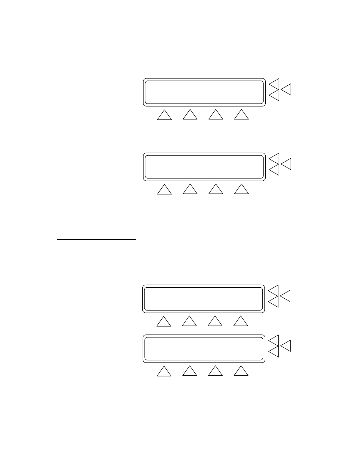
Front Panel
1. Key Pad
11 alphanumeric keys, used to enter information.
Delete: Prior to saving, deletes the last character
entered. After saving, deletes the entire
entry in the data field.
2. Function Keys
Enter: Saves data in field that was entered by
Only used for firmware upgrades.
See paragraph 3.8 below.
F1-F4 are used to select the functions shown in the
menu bar at the bottom of the display, i.e., for selecting the function that is directly above the key. F5-F7
are used to select a function, or enter information in
keying with the alphanumeric keys.
3-1
Page 16
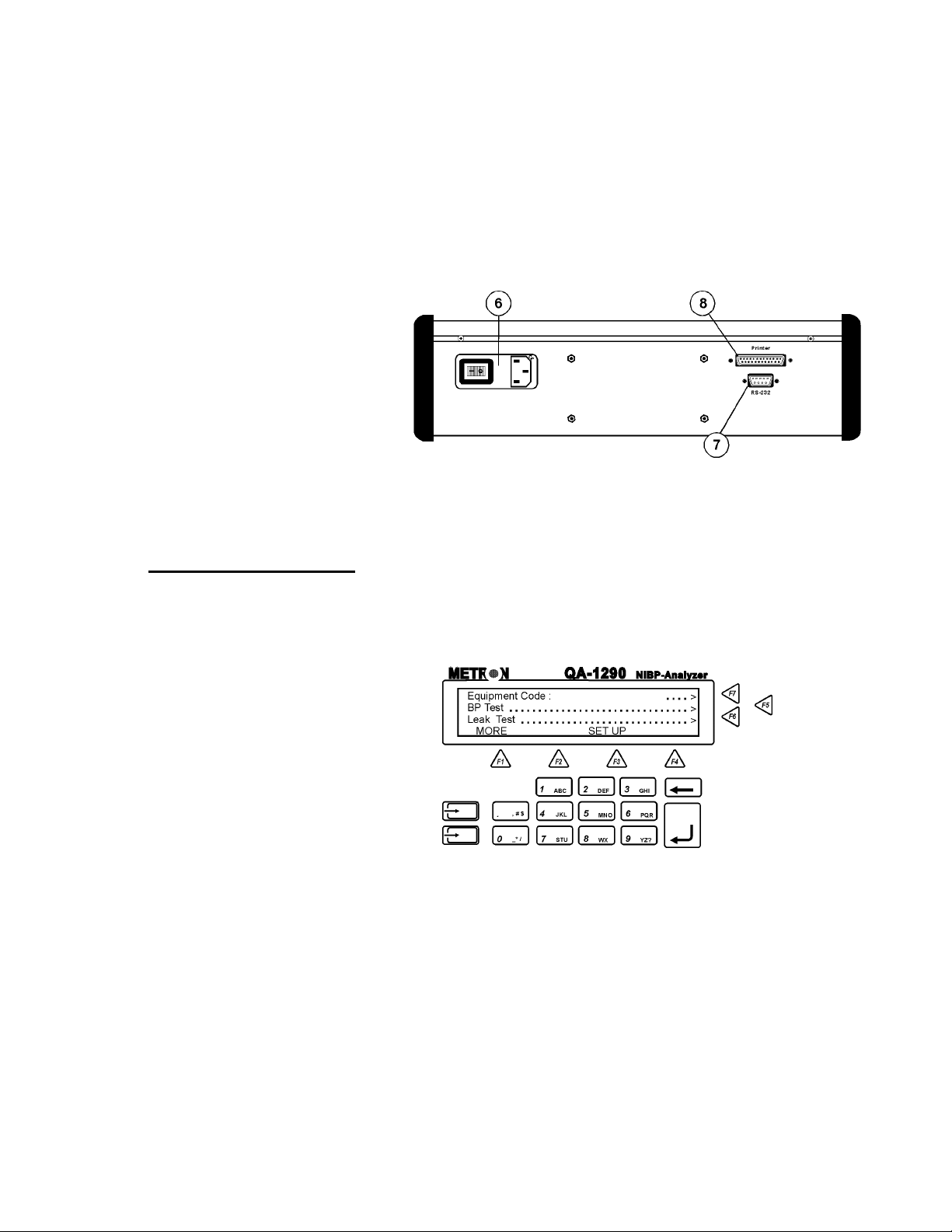
Rear Panel
3 LCD Display
4 Cuff Port
5. Inlet Port
the message field in the same line.
Shows messages, test results and function menus.
3.2 QA-1290’s Controls
6. Power Switch
and Mains
7. RS-232 Port
8. Printer Port
Power switch turns power ON and OFF. Mains connects the QA-1290 to the 110 VAC - 240 VAC, 47/63
Hz power source.
9-pin D-sub for Remote Control.
Bi-directional 25 pin D-sub. Centronic output.
QA-1290’s display, alphanumeric data entry keys, control keys and
programmable function keys provide flexibility and control in testing.
Operating them is very similar to operating a personal computer.
There are four text lines to each screen. The top three lines are used
for operator settings, system messages, and test status and results.
They are controlled by the F5, F6 and F7 keys, located to the right of
the display. Note, however, that these keys are active only when you
see the leading arrows (“. . . . . .>”) pointing to them. (See above)
3-2
The screen’s bottom line is a menu bar, controlled by function keys
F1 through F4 directly below the display. The menu is used for system functions, such as PRINT or INFLATE, and for inter-screen
navigation, such as MORE and GO BACK.
Page 17
3.3 QA-1290 Startup
Pressing and holding down one of the 11 alphanumeric keys causes it
to move automatically from character to character. For example,
pressing the “1 ABC” key and holding it down will scroll you automatically through “1”, then “A”, “B” and “C”. Release the key when
the desired alphanumeric character appears.
When QA-1290 is switched ON the following screens are displayed
in sequence. First, the system’s boot software and firmware versions
are displayed. Then, QA-1290 performs a self-check and prompts
you to zero the pressure before advancing to the Main Menu. (See be-
low)
****************************************
** M E T R O N **
** Boot software ver X.XX **
****************************************
****************************************
** METRON QA-1290 **
** Version. X.XX Date. XX.XXXXXX XXXX **
****************************************
****************************************
** METRON QA-1290 **
** Self Check. please wait......... **
****************************************
****************************************
** Pressure: x mmHg **
** Press any key to zero pressure **
****************************************
3.4 QA-1290 Main Menu
All QA-1290 operations start from the Main Menu, which consists of
two screens. They control the type tests to be conducted, and enable
you to configure QA-1290 settings and store them for use in testing.
Equipment Code .....> F7
Leak Test ............................> F6
BP Test ..............................> F5
MORE SET UP
F1 F2 F3 F4
3-3
Page 18
Main Menu Screen 1 (above) contains the following settings:
• Press Equipment Code (F7) to enter the facility code for
equipment being tested. Then press Enter to save.
• Press Leak Test (F6) to advance to the Leak Test screen.
• Press BP Test (F5) to advance to the BP Test screens.
• Press MORE (F1) to advance to Main Menu Screen 2. (See be-
low).
Over-Pressure Cut-Off Test ............> F7
Manometer ............................> F6
Print header/footer ...................> F5
GO BACK SET UP
F1 F2 F3 F4
• Press Over-Pressure Cut-Off Test/Manometer (F7) to advance
to that test’s screen.
• Press Manometer (F6) to advance to that test’s screen.
• Press Print Header / footer (F6) to advance to the Print Screen
(see paragraph 3.6 below).
• Press GO BACK (F2) to return to Main Menu Screen 1, SETUP
(F3) to advance to the Set Up Screen 1.
3.5 Configuring QA-1290
3-4
Pressing SETUP (F3) in either Main Menu Screen advances you to a
series of screens that allow you to configure QA-1290 settings and
store them for use in all testing. There are three Setup Screens.
SYSTEM SETUP F7
Operator :.........................> F6
Establishment:.........................> F5
MORE STORE MAIN MENU
F1 F2 F3 F4
Setup Screen 1. This screen (above) contains the following settings:
• Press Operator (F6). Use the alphanumeric keys to enter the
test operator’s name or other identifying data. Press Enter to
save.
Page 19

• Press Establishment (F5). Use the alphanumeric keys to en-
ter the test facility’s name or other identifying data. Press En-
ter to save.
• Press MORE (F1) to advance to Setup Screen 2.
• Press STORE (F2) to store all settings in QA-1290’s flash
memory.
Language: English .............> F7
Date : XX. XXXXXXX XXXX ..........> F6
Time : XX:XX:XX (HH:MM:SS) ......> F5
MORE STORE AM/PM MAIN MENU
F1 F2 F3 F4
Setup Screen 2. This screen (above) contains the following settings:
• Language (F7). This is installed with METRON’s Firmware
version. No selection.
• Press Date (F6). Use the alphanumeric keys to set, or reset,
the system date (DD/MM/YYYY). Press Enter to save.
• Press Time (F5). Use the alphanumeric keys to set, or reset,
the system clock (HH:MM:SS). Press F3 to specify the a 12hour (Am/Pm) or 24-hour (24 hour) clock. Note: When 24
Hour shows above F3, the system is operating on a 12-hour
time schedule. When showing “Am/Pm” above F3, the sys-
tem is operating on a 24-hour time schedule.
• Press MORE (F1) to advance to Setup Screen 3.
• Press STORE (F2) to store all settings in QA-1290’s flash
memory.
QA-1290 Serial no : XXXXX.............> F7
Report page length : 58 ..............> F6
FIRMWARE Version : X.XX F5
MORE GO BACK MAIN MENU
F1 F2 F3 F4
Setup Screen 3. This screen (above) contains the following settings:
• Press QA-1290 Serial no. (F7). Use the alphanumeric keys
to enter the QA-1290’s serial number. Press Enter to save.
• Press Report Page Length (F6). Use the alphanumeric keys
to set the length of the printed report.. The range is 10 to 999.
Press Enter to save.
3-5
Page 20
3.6 Printing Results
• This line shows the FIRMWARE version currently installed
in the QA-1290. No selection.
• Press GO BACK (F2) to advance to Setup Screen 1.
Setup Screen 4. Shown below allows the user to select different
units of pressure measurement for Manometer,Leak and Overpressure
testing only.
mmHg, cmH20, inH20, PSI, kPa, mBar
Pressure unit:mmHg ....................> F7
F6
F5
GO BACK MAIN MENU
F1 F2 F3 F4
A printed report may be prepared at the completion of testing. In each
test results screen that shows the digital readout you can select
PRINT (F5). The Print Screen appears.
Print Test Header .....................> F7
Print Test Footer .....................> F6
Form Feed .............................> F5
GO BACK MAIN MENU
F1 F2 F3 F4
• Print Test Header (F7). Selecting this prepares a Report Header
for printing. The header contains identifying information relative
to the facility and operator, the device under test, and QA-1290’s
setup configuration for the test.
• Print Test Footer (F6). Selecting this prepares a Report Footer
for printing. The footer is used for operator comments and signa-
ture.
• Form Feed (F5). Pressing this advances the page, currently being printed, in the printer.
• Press GO BACK (F2) to return to Test Screen.
• Press MAIN MENU (F4) to return to Main Menu Screen 1.
3-6
Page 21

3.7 Upgrading QA-1290
Firmware
To install new firmware, use the following procedure. Note that the
QA-1290 upgrade contains two files: com[xxxx].exe, which establishes communication between a PC computer and the QA-1290, and;
[xxxx].a07, which is the actual QA-1290 upgrade file. NOTE:
“[xxxx]” indicates the version of the firmware
1. Prepare the QA-1290 for the software upgrade.
• Press and hold the firmware upgrade keys on the keyboard
(see left) at the same time while turning the QA-1290 ON.
• The QA-1290 display will show the following:
The software in the QA-1290 is missing
To download new software, run COMM[XXXX]
on the PC and ENTER on the instrument
• The QA-1290 is ready to receive the firmware upgrade.
2. Prepare the PC for the upgrade.
• Connect an RS-232 cable between the PC and the QA-1290.
• Insert the disk that contains the QA-1290 upgrade files.
• Run comm[xxxx].exe, which is a DOS program.
• The computer will then display a menu.
3. Perform the upgrade.
• Choose menu 1 SET PARAMETERS and choose new pa-
rameters or default values.
• Choose menu 2 START COMMUNICATION by pressing
2. Enter filename [xxxx].a07 where XXXX is the version of
the firmware.
• Press ENTER (↵) on the PC.
• Press ENTER (↵) on the QA-1290 and the transmission will
start.
If the communication is successful, >>>>>>> appears on all lines
of the QA-1290’s display during the file transfer (see below).
3-7
Page 22

>>>>>>>>>>>>>>>>>>>>>>>>>>>>>>>>>>>>>>>>
>>>>>>>>>>>>>>>>>>>>>>>>>>>>>>>>>>>>>>>>
>>>>>>>>>>>>>>>>>>>>>>>>>>>>>>>>>>>>>>>>
>>>>>>>>>>>>>>>>>>>>>>>>>>>>>>>>>>>>>>>>
At the end of the transfer, a normal startup sequence will occur.
4. Test to confirm the upgrade.
• Exit the DOS program and unhook the RS-232 transfer cable from the QA-1290.
• Switch the QA-1290 OFF, then turn it back ON.
Verify that the new firmware version is installed while the QA1290 is running its start sequence. The firmware version will be
displayed in Startup Screen Menu 3.
3-8
Page 23

4. Blood Pressure Testing
This chapter describes step-by-step procedures for conducting QA1290 blood pressure testing.
Blood pressure simulation is the most complex of the QA-1290’s
functions. It simulates a number of different patient conditions, each
of which can be selected by the operator. These conditions include a
large number of systolic, diastolic and heart rate values, as well as
different types of irregular pulses.
Three aspects of the QA-1290 should be noted:
1. Many different types of blood pressure monitors were used during QA-1290’s development in order to ensure its compatibility
with them. However, we have optimized QA-1290 for the widely
used Criticon Dinamap Blood Pressure Monitor. Thus, measured
values may differ somewhat from the selected values when testing monitors other than the Criticon Dinamap monitor. However,
since QA-1290 is used for functional verification, and not calibration, these differences should not be of significant concern.
2. QA-1290 simulations are suitable only for oscillometric blood
pressure measurements. In other words, it can be used only for
testing monitors that measure the pulse pressure variations to
find the systolic and diastolic values. QA-1290 is not intended
for use in testing monitors that acoustically measure systolic and
diastolic values.
4.1 Measuring Cuff Volume
3. During simulations the real cuff is disconnected, and an internal
pressure chamber is used. This is for two reasons. One is that this
makes it possible to optimize the QA-1290’s pressure generator,
because it then only needs to cope with a known volume (i.e.,
needed pulse volume for a given pulse varies with the cuff volume). The other reason is that the internal “cuff” is made of aluminum, which makes it rigid compared to real, rubber cuffs.
This, in tern, makes it possible to obtain better control over pulse
generation.
From Main Menu Screen 1 press BP Test (F5). This advances you to
the BP Test Index Screen. Press Measure Cuff Volume (F7). This
advances you to the screens controlling cuff volume measuring.
Equipment Code : ......................> F7
Leak Test .............................> F6
BP Test ...............................> F5
MORE SET UP
F1 F2 F3 F4
4-1
Page 24

Measure Cuff Volume ...................> F7
Adult Preset Simulations...............> F6
Neonate Preset Simulations.............> F5
MORE GO BACK START MAIN MENU
F1 F2 F3 F4
Press START (F7). Pressurization of the cuff begins. The screen
changes while measurement occurs (see below), and a new menu
item, ABORT (F3) is added, which can be used to stop pressurization.
Measure Cuff Volume F7
Cuff Volume = XXX ccm F6
F5
START GO BACK MAIN MENU
F1 F2 F3 F4
Measure Cuff Volume F7
Please Wait..... F6
F5
GO BACK ABORT MAIN MENU
F1 F2 F3 F4
When the measurement is completed the cuff volume is displayed in
cubic centimeters. Press GO BACK (F2) to return to the BP Test Index Screen.
4.2 Setting Test Parameters
4-2
4.21 Preset Simulations ( select BP Test from Main Menu )
QA-1290 simulates a variety of patient conditions through preset and
programmable parameters. To select Adult Preset blood pressures
select (F6) below and (F5) for Neonate Preset Simulations.
Measure Cuff Volume ...................> F7
Adult Preset Simulations...............> F6
Neonate Preset Simulations.............> F5
MORE GO BACK START MAIN MENU
F1 F2 F3 F4
In either case you advance to a series of three screens in which
you select the appropriate preset. The presets are diastolic/ systolic pressure, mean arterial pressure (MAP), heart rate (HR) and
pulse pressure (PP). (See the first screen in the sequence below).
Page 25

60/30 (40) HR:80 BPM PP:2.00 mmHg.> F7
80/48 (58) HR:80 BPM PP:2.00 mmHg.> F6
100/65 (77) HR:80 BPM PP:2.00 mmHg.> F5
MORE GO BACK START MAIN MENU
F1 F2 F3 F4
To select the desired preset use the F5, F6 or F7 key. The corresponding line will flash intermittently to indicate the selected preset. Below are the adult and neonate preset pressures.
Adult Preset Pressures
Diastolic//Systolic
(mmHg)
60 / 30 40 80 3.00
80 / 48 58 80 3.00
100 / 65 77 80 3.00
120 / 80 95 80 3.00
150 / 95 114 80 3.00
200 / 140 167 80 3.00
255 / 195 215 80 3.00
Diastolic//Systolic
(mmHg)
60 / 30 40 120 1.50
80 / 48 58 120 1.50
100 / 65 77 120 1.50
120 / 80 95 120 1.50
150 / 95 114 120 1.50
200 / 140 167 120 1.50
255 / 190 220 120 1.50
MAP (mmHg) Heart Rate
(BPM)
Neonate Preset Pressures
MAP (mmHg) Heart Rate
(BPM)
Pulse Pressure
(mmHg)
Pulse Pressure
(mmHg)
In the present pressure screen menu keys press:
• MORE (F1) to advance to the next preset screen.
• GO BACK (F2) to return to the Adult/Neonate Screen.
• START (F3) to advance to the BP Test Screen.
• MAIN MENU (F4) to return to Main Menu Screen 1.
4.22 Independent Test Parameters (F1). From the menu shown below( from BP Test at Main Menu) select more and then (F7) to set
the desired blood pressure, heart rate or pulse amplitude and Arrhythmias.
4-3
Page 26

Measure Cuff Volume ...................> F7
Adult Preset Simulations...............> F6
Neonate Preset Simulations.............> F5
MORE GO BACK START MAIN MENU
F1 F2 F3 F4
Independent Test Parameters............> F7
Artifact Simulations ...........> F6
Custom Patient Pattern Mode............> F5
GO BACK MAIN MENU
F1 F2 F3 F4
INDEPENDANT TEST PARAMETER F7
Sys: 120 Dia: 80 HR: 80 PP:3.00 ..> F6
Arrhythmia Simulations: Off ..> F5
STORE GO BACK START MAIN MENU
F1 F2 F3 F4
Press the F6 key to enter the desired pressure and heart rate settings. Once F6 is pressed a cursor appears in the setting that is to
be changed. Use the alphanumeric keys to enter the following setting(s):
• Systolic pressure (Sys) setting, between 20 and 255 mmHg.
• Diastolic pressure (Sys) setting, between 5 and 220 mmHg.
• Heart rate (HR) setting, between 10 and 200 BPM.
• Pulse pressure (PP) setting, between .05 and 5.00 mmHg.
Press the STORE F1 key to save the new setting(s).
Press the F5 key to scroll through the arrhythmia simulations.
Available selections, in sequence, are: Off, PAC, AFIB, 2-BLK
II, PVC STD, and Artifact. When scrolling, each simulation
flashes intermittently to indicate that it is not yet entered as a preset. Press the Enter key to set the desired simulation. Once set,
the intermittent flashing stops.
In the Independent Test Parameter Screen Menu press:
• STORE (F1) to store the settings in flash memory.
• GO BACK (F2) to return to the BP Test Parameters Index.
• START (F3) to advance to the BP Test Screen.
• MAIN MENU (F4) to return to Main Menu 1.
4-4
Page 27

4.23 Artifact Simulations (F6). Pressing this advances you to a se-
ries of three screens, in which you select the desired artifact to use
in the BP testing. To get to this Menu press BP TEST(F5) from the
Main Menu and then more (F1)
Independent Test Parameters ...........> F7
Artifact Simulations ..........> F6
Custom Patient Pattern Mode............> F5
GO BACK MAIN MENU
F1 F2 F3 F4
Each of these Artifact Simulation Screens contains the simulated
condition, along with the preset diastolic/systolic pressures, mean
arterial pressure (MAP), and heart rate (HR). (See the first screen
in the sequence below).
Bradycardia 120/60 (80) HR:45 .> F7
Tachycardia 60/30 (40) HR:140.> F6
Geriatric subject 150/110 (123) HR:95 .> F5
MORE GO BACK MAIN MENU
F1 F2 F3 F4
To select the desired preset use the F5, F6 or F7 key. When
pressed you advance to another screen, indicating the condition’s
pulse pressure (PP). You also have the option at this point of selecting between adult or neonate settings for this condition. (See
the Bradycardia Artifact Screen in the sequence below).
4-5
Page 28

CHOOSE ADULT/NEONATE F7
Bradycardia PP=2.50 mmHg F6
NEONATE .> F5
GO BACK START MAIN MENU
F1 F2 F3 F4
Below are the preset selections in the Artifact Simulation Screens.
Artifact Simulation Selections
Condition Sys./Dia.
(mmHg)
Bradycardia 120 / 60 80 45 2.50 1.25
Tachycardia 60 / 30 40 80 0.80 0.40
Geriatric subject 150 / 110 123 95 1.00 0.50
Obese subject 120 / 80 93 90 1.00 0.50
Strenuous exercise 140 / 90 106 160 3.00 1.50
Mild exercise 140 / 90 106 120 2.50 1.25
Weak pulse 110 / 80 89 95 0.80 0.40
MAP
(mmHg)
HR
(BPM)
PP (mmHg)
Adult Neonate
In the Artifact Simulations Screen Menus press:
• MORE (F1) to advance to the next simulation screen.
• GO BACK (F2) to return to the previous simulation screen.
4.3 Running BP Tests
• START (F3) to advance to the BP Test Screen.
• MAIN MENU (F4) to return to Main Menu Screen 1.
• ADULT / NEONATE (F5) to select adult or neonate set-
tings for the condition displayed. Note: When NEONATE
shows at F5, the current setting is “Adult”. When showing
ADULT at F5, the current setting is “Neonate”.
4.24 Custom Patient Pattern Mode (F5). This is the fourth test pa-
rameter, and is used for the downloading of arbitrary patient patterns
via Ansur QA-1290 Plug-in software.
From Main Menu Screen 1 press BP Test (F5). This advances you to
the BP Test Index Screen. Press Adult Preset Simulations(F6) and
(F3) to start the test.
4-6
Page 29

Equipment Code : ......................> F7
Leak Test .............................> F6
BP Test ...............................> F5
MORE SET UP
F1 F2 F3 F4
Measure Cuff Volume ...................> F7
Adult Preset Simulations...............> F6
Neonate Preset Simulations.............> F5
MORE GO BACK START MAIN MENU
F1 F2 F3 F4
60/30 (40) HR:80 BPM PP:2.00 mmHg.> F7
80/48 (58) HR:80 BPM PP:2.00 mmHg.> F6
100/65 (77) HR:80 BPM PP:2.00 mmHg.> F5
MORE GO BACK START MAIN MENU
F1 F2 F3 F4
The screen changes when the test is started (see below). The top line
of the screen specifies the settings for the test, and includes the preset
diastolic/systolic pressures, mean arterial pressure (MAP), heart rate
(HR), pulse pressure (PP), and what arrhythmia simulation is used (if
any).
60/30 (40) HR: 80 PP:2.00 Off F7
Manometer: 0 mmHg Peak: 0 mmHg F6
Time : 0 sec PRINT....> F5
GO BACK MOTION MAIN MENU
F1 F2 F3 F4
The second and third lines display test readings for the manometer
and peak pressure in millimeters of mercury (mmHg), and the inflation time in seconds.
In this test screen’s menu press:
• GO BACK (F2) to return to the BP Test Index Screen.
• MOTION (F3) to initiate a motion/tremor artifact in the testing.
This is to test exactly how a BP monitor responds to calibrated
levels of motion and tremor.
• MAIN MENU (F4) to return to Main Menu Screen 1.
• PRINT (F5) if you want to print the test results. This advances
you to the Print Screen.
4-7
Page 30

This page intentionally left blank.
4-8
Page 31

5.1 Leak Test
5. Leak, Manometer, and Over-Pressure
Cut-off Testing
This chapter describes step-by-step procedures for conducting QA1290 Leak and Over-Pressure Cut-off Tests.
The Leak Test is used to detect any leakage in the cuff, hose or connections within the monitor. For this test the QA-1290 pumps up a
pressure and then measures the air leakage over time. There should
be no leakage. However, if any exists, then it should be minimal (less
than 1 mmHg per minute).
The Over Pressure Cut-off Test is used for testing the blood pressure
monitor’s security valve. Monitors have these valves to release pressure if it rises above a certain value, thus protecting the patient
against too high a pressure in the event of a monitor malfunction.
QA-1290 increases the pressure to a predefined value. If the value
exceeds the monitor’s release pressure, the monitor will release. QA1290 will then indicate that the security valve is functioning correctly
by indicating “OK”. If the pressure is not released before the predefined pressure level is reached, QA-1290 will display an error message.
1. From Main Menu Screen 1 press Leak Test (F6). This advances
you to the Leak Test Screen..
Equipment Code : ......................> F7
Leak Test .............................> F6
BP Test ...............................> F5
MORE SET UP
F1 F2 F3 F4
Manometer: 0 mmHg Peak: 0 ZERO PR.> F7
Drop : 0 mmHg Time:00:00 RS PEAK.> F6
Leak Rate: 0 mmHg/min PRINT ..> F5
RESTART INFLATE SET UP MAIN MENU
F1 F2 F3 F4
5-1
Page 32

Press SETUP (F3). This advances you to the Start Pressure
2.
Screen. (See below).
Start Pressure: XXX mmHg ......> F7
Test object : Cuff ......> F6
F5
STORE GO BACK MAIN MENU
F1 F2 F3 F4
3. Use the alphanumeric keys to enter the Start Pressure (F7) setting to between 0 and 400 mmHg. Press the Enter key to save
the new setting(s). Use the Delete key to clear the current setting.
4. Scroll through Test Object (F6) to enter the device under test.
Available options are: Cuff, Monitor, and Cuff and Monitor.
5. Press:
• STORE (F1) to store the settings in flash memory.
• GO BACK (F2) to return to the Leak Test Screen.
• MAIN MENU (F4) to return to Main Menu 1.
Manometer: 0 mmHg Peak: 0 ZERO PR.> F7
PressDrop: 0 mmHg Time:00:00 RS PEAK.> F6
Leak Rate: 0 mmHg/min PRINT ..> F5
RESTART INFLATE SETUP MAIN MENU
F1 F2 F3 F4
6. Press INFLATE (F2). The menu changes and DEFLATE (F2)
becomes active (see below). Wait until the inflation stops. When
the test results are shown, press DEFLATE.
7. To reset the manometer and peak values to 0 mmHg, press
ZERO PR (F7) and RS PEAK (F6). Note that this also resets
the time to zero.
Manometer: 0 mmHg Peak: 0 ZERO PR.> F7
PressDrop: 0 mmHg Time:00:00 RS PEAK.> F6
Leak Rate: 0 mmHg/min PRINT ..> F5
RESTART INFLATE SETUP MAIN MENU
F1 F2 F3 F4
8. To repeat the test, press RESTART (F1), which resets the results
to zero. Then, press INFLATE.
5-2
Page 33

5.2 Over-Pressure Cut-Off
Test
1. Advance to Main Menu Screen 2. From this screen press OverPressure Cut-Off Test (F7). This advances you to the test
screen.
Equipment Code : ......................> F7
Leak Test .............................> F6
BP Test ...............................> F5
MORE SET UP
F1 F2 F3 F4
Over-Pressure Cut-Off Test ............> F7
Manometer .............................> F6
Print header/footer ...................> F5
GO BACK SET UP
F1 F2 F3 F4
2. Press SET UP (F3). This advances you to the Inflate Pressure
Screen. (See below).
Manometer: 0 mmHg ZERO PRESSURE.> F7
Peak: 0 mmHg RESET PEAK ...> F6
PRINT ........> F5
INFLATE SET UP MAIN MENU
F1 F2 F3 F4
Inflate Pressure:XXX mmHg F7
F6
F5
STORE GO BACK MAIN MENU
F1 F2 F3 F4
3. The Inflate Pressure (F7) value must be entered. Otherwise the
test will fail. Use the alphanumeric keys to enter the pressure setting to between 0 and 500 mmHg. Press the Enter key to save
the new setting(s). Use the Delete key to clear the current setting.
4. Press:
• STORE (F1) to store the settings in flash memory.
• GO BACK (F2) to return to the Over-Pressure Cut-Off Test
Screen.
5-3
Page 34
• MAIN MENU (F4) to return to Main Menu 1.
Manometer: 0 mmHg ZERO PRESSURE.> F7
Peak: 0 mmHg RESET PEAK ...> F6
PRINT ........> F5
INFLATE SET UP MAIN MENU
F1 F2 F3 F4
5. Press INFLATE (F2). The menu changes and DEFLATE (F2)
becomes active (see below). Wait until the inflation stops. When
the test results are shown, press DEFLATE.
Manometer: 0 mmHg ZERO PRESSURE.> F7
Peak: 0 mmHg RESET PEAK ...> F6
PRINT ........> F5
DEFLATE SET UP MAIN MENU
F1 F2 F3 F4
6. To reset the manometer and peak values to 0 mmHg, press ZERO
PRESSURE (F7) and RESET PEAK (F6). Note that this also
resets the time to zero.
7. If you want to print the test results, press PRINT (F5) to advance
to the Print Screen.
5.3 Manometer
This test will let you select a pressure in mmHg and maintain it.
1. Advance to Main Menu Screen 2. From this screen press Ma-
nometer (F6). This advances you to the test screen.
Equipment Code : ......................> F7
Leak Test .............................> F6
BP Test ...............................> F5
MORE SET UP
F1 F2 F3 F4
Over-Pressure Cut-Off Test ............> F7
Manometer .............................> F6
Print header/footer ...................> F5
GO BACK SET UP
F1 F2 F3 F4
5-4
Page 35

2. Press SET UP (F3). This advances you to the Inflate Pressure
Screen. (See below).
Manometer: 0 mmHg ZERO PR.> F7
PRINT...> F6
Set Pressure: 300 mmHg ...............> F5
REGULATE SET UP MAIN MENU
F1 F2 F3 F4
Test object: Monitor ................> F7
F6
F5
STORE GO BACK MAIN MENU
F1 F2 F3 F4
3. Press Test object (F7). This allows you to select between Moni-
tor and Cuff and Monitor as the port being used.
4. Press STORE (F1) to save the settings then press GO BACK
(F2) to return to the manometer test.
Manometer: 0 mmHg ZERO PR.> F7
PRINT...> F6
Set Pressure: 300 mmHg ..............> F5
REGULATE SET UP MAIN MENU
F1 F2 F3 F4
5. To reset the manometer to 0 mmHg, press ZERO PR (F7).
6. If you want to print the test results, press PRINT (F6) to advance
to the Print Screen.
7. Press Set Pressure (F5) to key in the pressure that you wish the
QA-1290 to maintain.
8. Once you have completed your setup press REGULATE (F2) to
begin pressure regulation.
Note: It is possible to change the pressure units for the Leak,
Manometer and OverPressure tests. From the Main Menu press
(F3) setup and more (F1) 3 times until the menu item is displayed.
Pressure Unit: mmHg………………………> F7
Press F7 for the desired pressure units. mmHg, cmH20, inH20,
PSI, kPa, or mBar.
5-5
Page 36

This page intentionally left blank.
5-6
Page 37

6.1 Required Equipment
6.2 Testing Procedures
6. Testing and Maintenance
This chapter covers QA-1290 testing, as well as maintenance and
troubleshooting procedures.
• Digital voltmeter, e.g. Fluke 87
• Pressure instrument, e.g. Drück DPI-601
1. Power Supply
• Connect +5.0 v and +24.0 v on P300.
• Measure the following voltages are referenced to ground on
T307.
Reference Nominal value
T300 - T307
T306 - T307
T301 - T307
T302 - T307
T303 - T307
T304 - T307
T305 - T307
+24.0 V ± 7%
+5.0 V ± 5%
+15.0 V ± 5%
+12.0 V ± 5%
-12.0 V ± 5%
+5.0 V ± 5%
-5.0 V ± 5%
2. Analog Ground. Verify that the analog and digital grounds on
T307 – T150are tied together. The nominal value is 0 Ω + 0.1 Ω.
3. Reference Voltages. Inspect the following voltages referenced
to ground on T150. Nominal values are as follows:
Reference Nominal value
T153 - T150
T154 - T150
T155 - T150
+5.0v ± 5%
+12.1v ± 5%
-1.2v ± 5%
4. A/D converter
• Measure the frequency of the oscillator on the A/D con-
verter on T156. The nominal value is 4 MHz ± 20 kHz.
• Check the amplitude on the oscillator on T156. The nominal
value is 5.0V ± 0.5V.
5. Functional QA-1290 System Test
• Connect signal- and power cables to front board, step motor,
compressor and valve. Turn on the power.
• Verify in display that system runs and that SW starts.
6-1
Page 38

6.3 Cleaning and
Sterilization
• Verify that buzzer beeps when system starts.
• Verify that step motor first moves against cylinder, then away
from cylinder on startup.
• With the unit in main menu all valves are open. Measure
voltage over each valve control output:
Valve Nominal value
1
2
3
23 V ± 5%
23 V ± 5%
23 V ± 5%
• Enter the Leak Test menu and press INFLATE (F2), then
DEFLATE (F2). Verify that compressor starts on INFLATE
and stops on DEFLATE.
The QA-1290 should not require sterilization if used as recommended. The outside of the QA-1290 may be cleaned with warm
soapy water, isopropyl alcohol, or a weak bleach solution.
DO NOT ALLOW FLUIDS TO ENTER THE ENCLOSURE OF
THE UNIT!
The cuff mandrels and tubing adapters may be sterilized using liquid,
gas, or light techniques, if items are inadvertently contaminated.
6-2
Page 39

7.1 Calibration
7. Calibrating QA-1290
This chapter covers procedures for calibrating QA-1290. This is a
rather simple task, since only the pressure sensor circuit needs calibration. The unit must be opened to perform the calibration.
WARNING!
HIGH VOLTAGES ARE CAPABLE OF
USE EXTREME CAUTION WHEN PERFORMING TESTS AND CALIBRATION. USE ONLY INSULATED TOOLS WHEN THE UNIT IS
PLUGGED IN, AND THE CASE HOUSING IS OFF.
1. Required Calibration Equipment
• Digital voltmeter, e.g. Fluke 87
• Pressure calibration instrument, e.g. Drück DPI-601
THE QA-1290 MUST BE POWERED ON FOR AT LEAST 30 MINUTES PRIOR TO CONDUCTING ANY TESTING.
CAUSING DEATH!
IMPORTANT!
BEFORE TESTING
2. Offset Adjustment
a. Connect - lead of voltmeter to T150 on the QA-1290 board
and the + lead to T151.
b. Power up the unit and stop at the zero adjustment menu.
c. With a screwdriver adjust R101 (offset adjustment) until the
voltmeter displays 0.000V (5mV. The display on the QA1290 shall read 0.
4. Gain Adjustment
a. Enter the "LEAK TEST" menu.
b. Connect the pressure pump to the cuff connection.
c. Reset pressure pump display to zero.
d. Pump up the pressure to 495 mmHg (660 mBar)
e. Adjust R100 (gain) until the display shows 495 mmHg
7-1
Page 40

f. Release pressure and verify that the display reads 0, if
not: power off and repeat from step 2.
g. Check the calibration and linearity by applying pressure of
330 mmHg (440 mBar) and 165 mmHg (220 mBar), and
verify that the QA-1290 displays this value ± 1mmHg.
Pressure sensor
Reference
0 mBar (0 mmHg)
220 mBar (165 mmHg)
440 mBar (330 mmHg)
660 mBar (495 mmHg)
*Tolerance Pressure Sensor: ± 1 mmHg
Measured value
5. The calibration procedure is now complete.
7-2
Page 41

8.1 System Overview
8. Component Functions and Parts
This chapter provides a description of the functions of the main components of the QA-1290, as well as a parts list for cross-reference.
QA-1290 consists of three different modules inside the cabinet: processor and keypad board in the front of the cabinet; the QA-1290
board located on the left side of the cabinet bottom, and; the power
supply located on the middle of the cabinet rear wall. There are also a
number of pneumatic parts to generate pressure and pulses for the
simulations and tests. The processor and keypad boards, with two
modifications, are the same as those on the QA-90. The QA-1290
board contains drivers for valves, the step motor, the compressor and
the pressure measurement circuit. It also generates the supply voltages needed in addition to +5V and +24V. Communication between
the processor and QA-1290 boards is by a 16-conductor ribbon cable.
The following block diagram shows the hardware used in the QA-
1290. The electronic components are found on the QA-1290 board,
as well as the processor and keypad boards.
8-1
Page 42

8.2 QA-1290 Pressure
Measurement System
Refer to Appendix C, Drawing No. 1001-01-02, containing eight
schematic diagrams.
1. Pressure Sensor and Amplifier. Refer to Schematic Diagrams
1, 5 and 6 (Top Level, A/D Converter and Pressure Sensor and
Amplifier. The pressure sensor used is the Honeywell (gauge
type) 136PC15G2. The sensor is based on a piezo-resistive
measuring bridge. It is temperature-compensated internally, but
has no built-in amplifier. It is powered with 12V, which is a reference voltage that is internally generated from the 5V-reference
voltage on the A/D-converter. The voltage is generated by U102C. The sensitivity of the pressure sensor is 128.92 µV/mmHg
(6,67mV/psi). The pressure range is 0 to 775.7 mmHg (0 – 15
psi). This gives a full-scale output (FSO) of 100 mV. Initial tolerance on FSO is ± 1.5%, and for offset voltage it is max ±
1.0mV
The amplifier takes the signal from the pressure sensor to a
maximum output voltage of 5.00 V at maximum pressure.
Maximum pressure is defined to be 512.0 mmHg. This gives a
nominal amplification of 75.8 The amplifier used is a JFET OPAMP, LF 347. Two multi-turn potentiometers are used for adjustment of offset and gain for the pressure sensor circuit. For
offset adjustment the two reference voltages of 12.1 V and - 1.2
V is used. Offset is adjusted with R101. Gain is adjusted with
R100. Refer to Schematic Diagram 8 (Component Notation, Bot-
tom Side).
8-2
The amplified signal passes through a second order low-pass fil-
ter. The roll-off frequency is about 15 Hz.
2. A/D-Converter. Refer to Schematic Diagrams 1, 2 and 5 (Top
Level, Power and A/D Converter. The A/D-converter used is the
National Semiconductor ADC12030. This is a 12 bit (plus sign)
A/D with SPI-bus interface to the micro controller. The hardware
SPI on the micro controller is not used, as the pins are used for
other purposes. Instead the SPI is implemented in QA-1290’s
firmware, using ordinary I/O-port pins. The communication uses
the signals MOSI, MISO, SCKB (SPI-signals) and AD_CS
(chip select). For a description of the data format refer to the data
sheet for the A/D-converter. The signal AD_EOC indicates
when a conversion has finished and the data are available for retrieval from by the µC. A measurement range of 5V and 12 bit
gives a resolution of 5/(2
12
) = 1.22mV per step. A 4 MHz oscilla-
tor generates the converter clock.
The Voltage Reference for the A/D-converter is 5V. This voltage defines the range for the A/D-converter. From this reference,
Page 43

a reference voltage of 12.1V and a reference of –1.2V are generated.
An I/O-expansion is needed to obtain the I/O for the processor.
A SIPO (Serial In Parallel Out) shift register is used. The outputs
of this register control three magnet valves, and a miniature air
compressor, beeper, step motor (step motor inhibit signal) and
dual-color LED. Note: The LED is currently not used, except for
development tests.
3. Stepper Motor Driver. Refer to Schematic Diagrams 1 and 4
(Top Level and Stepper Motor Driver. The Ericcson PBD3517N
is used as the stepper motor driver. The motor is run in half step
mode to obtain an optimum of force and speed. The half step reduces the potential problems of resonance (increased noise for
system at certain motor speeds) in the system. The driver is controlled by the signals STEP_INHIBIT-, STEP_DIR, STEPB-
and STEP_CNT. These signals have the following function:
STEP_INHIBIT-:
STEP_DIR:
STEPB-:
STEP_CNT:
‘L’ = power down, ‘H’ = active
Direction of rotation
Motor speed – frequency from UARTs 16-bits timer
Counting pulses to measure motor movement
There are three magnet valves that are controlled via the SIPO
shift register. The coils are driven by 24 V, with grounding via a
ULN2003 Darlington driver output. These outputs have internal
protection diodes that prevent the ULN2003 from the back voltage induced by the coil of the magnet valves when valve is released.
The miniature air compressor used for leak- and overpressure
tests is driven by three ULN2003 Darlington driver outputs in
parallel. Supply voltage to compressor is 24 V. The outputs are
internally protected against back voltages from inductive loads.
A beeper with built-in oscillator is driven by a ULN2003 Darlington driver output, which is controlled by the shift register.
The beeper voltage is 24V. In case a lower volume is desired, a
serial resistor is prepared for and may be fitted on the board. The
beeper is controlled with the signal BEEPER.
From the Power supply, the QA-1290 board gets +5V and
+24V. From these the rest of the needed voltages are generated
on the QA-1290 board. The following voltages are present in the
system:
Voltage Generated from Description
+24 External Supply Regulated 24V in
+15 +24 Local +15V analogue
+12 +24 +12V analogue for QA-90
-12 +12 -12V analogue for QA-90
+5A +24 Local +5V analogue
-5A +5 Local -5V analogue
8-3
Page 44

8.3 Processor System
Voltage Generated from Description
+5 External Supply Regulated 5V in, digital 5V
Refer to Appendix C, Drawing No. E160.20.1000.U1, containing six
schematic diagrams.
The QA-1290 processor board is identical to that used by the QA-90,
except for two modifications. One is that the buzzer on the processor
board is not used and is not fitted. A buzzer on the QA-1290 board is
used instead. The second is that Pin 3 on J60 is strapped to pin 13 on
U1300 instead of +5V. This signals the pulses that step the step motor.
Refer to Schematic Diagrams 1 through 3 (QA-90; Integrated Keyboard QA-90; and CPU QA-90). The processor controls the simula-
tions and measurements in the QA-1290. This system is divided into
five function blocks comprising a CPU, memory, display and printer
interface, serial and keypad interface and keypad.
The CPU and keypad board are located behind the front panel. The
unit comprises a processor system, display, control components and a
firmware-controlled SIP port for communication with the QA-1290
board.
The CPU comprises a Motorola 68HC11 operating at 8 MHz, which
gives a BUS frequency of 2 MHz. The UART in µP is used only during boot-up. A Maxim µP supervisory circuit with a 4.65 V reset is
used to monitor the 12 V power, and ensure battery power to RAM
when the unit is switched off. U1080 and DS2404 are timer circuits.
These provide the system with real time clock and calendar information. U1160 is an address decoder. U1120 is an address latch for the
multiplex address bus. µP has a 64 KB address range, and U1130 together with U1150 are used as a bank-switch to address the process
circuit’s RAM and Flash-ROM.
8-4
Refer to Schematic Diagram 4 (Memory QA-90). The memory component comprises 128 KB RAM and either a 28F200 or a 28F400
Flash-ROM for storing programs. The CPU module is programmable
and may be re-programmed with new software supplied by Metron.
Transistors in the memory circuit are used to supply the flash-ROM
with a 12 volt programming voltage.
Refer to Schematic Diagram 5 (Printer and Display IF, QA-90). The
printer and display interface comprises PD71055, PIO that is used to
write to display and to the Centronics output. Data to Centronics goes
via LS05, which has an open collector output. A strobe pulse to the
Centronics port is established through U1410. Keypad scanning and
the RS-232 interface are established by U1300, DUART. The keypad
is a standard keypad matrix. U1310, MAX238 is an RS-232 transmitter/receiver between DUART and the RS-232 port.
Page 45

8.4 Pneumatic System
The pneumatics and drivers are the QA-1290’s mechanical parts that
deal with the air pressure and pulse generation, and their electrical
drivers. This involves the electrically operated air valves that control
airflow with the cylinder and piston. These are, in turn, controlled by
the stepper motor in order to generate pulses. The system is used for
generating blood pressure pulses and to set up pressure for leakage test
and over pressure test. The following diagram shows the QA-1290
pneumatic system’s functions.
QA-1290 Pneumatic System Drawing
Device Under Test
Cuff
Ventilate
Valve
Valve Block
Pressure
Sensor
Cuff
Valve
Internal "Cuff" (fixed volum)
Step motor /
linear actuator
Blood Pressure Monitor
Monitor
Valve
Pneumatic Cylinder
Compressor
QA-1290
A miniature compressor generates the pressure needed for the Leak and
Over-Pressure Cutoff Tests. It is also used during blood pressure simulations for creating minor, rapid increases in pressure to simulate that
patient movement (i.e., when you press MOTION (F3)). Because the
compressor may have a little leakage that affects the leak test, a back
valve is inserted between the compressor and valve block.
The valve block has three valves to control the airflow. One connects
and disconnects the blood pressure monitors to the pneumatic system.
The second valve connects and disconnects the cuff to the pneumatic
8-5
Page 46

system, and the third valve is used to ventilate the system in order to
release pressure.
The following is a simplified explanation to illustrate the functioning
of these valves during a blood pressure simulation sequence:
1. When entering a simulation start menu all valves are open, so the
system is ventilated. Once the start menu is entered, the ventilate
valve is then closed.
2. As the blood pressure monitor increases the pressure, the pressure sensor detects this activity. The stepper motor then starts to
move the piston in the cylinder in order to simulate pulses. The
length of movement is given by the number of pulses applied to
the stepper motor.
3. As the pressure rises, the pulses increase in strength up to a
maximum where it starts falling again. At a high pressure the
pulses almost disappear. This is detected by the monitor, which
then starts to release the pressure slowly while simultaneously
monitoring the pulses.
4. QA-1290’s firmware calculates the pulse strength on the basis of
the pressure measured. This makes the pulse envelope look like
the pulse envelope of a human.
5. When the monitor has found both the systolic and diastolic pressures, it releases the pressure. QA-1290 senses that the measurement is completed, displays or prints the simulated values,
and ventilates the system. QA-1290 is then ready for a new
simulation.
8.5 Power Supply
8.6 Connector Signals
8-6
The Processor and QA-1290 boards are powered by the same power
supply. This supply delivers +5V and +24V to the QA-1290 board.
This board generates the additional voltages –5V, +12V, -12V and
+15V required.
The following are specifications for the ASTEC LPT65 Power Supply
used in the QA-1290:
Output Voltage Minimum load Maximum Load Peak Load
+5 V 0.7 A 7 A 10 A
+24 V 0.1 A 1.5 A 3 A
This power also has a 12V output but this is not used.
Input specifications for this power are 85 – 264 VAC, 120 –370 VDC,
47 – 440 Hz, and a maximum input RMS current at 115V.
1. Stepper motor
Page 47

Pin out:
Pin description:
Pin no: Signal Description
1 MA1 Winding 1 on step motor
2 n.c.
3 MB1
4 MA2 Winding 2 on step motor
5 n.c.
6 MB2
Winding 1
Winding 2
2. Magnet valves
Pin out:
Pin description magnet valves:
Pin no: Signal Description
1 +24V +24V after filter
2 VALVE1-3 Active LOW (GND)
3. Mini Compressor
Pin out:
on step motor
on step motor
Pin description:
Pin no: Signal Description
1 +24V +24V after filter
2 COMPRESSOR Compressor output, active LOW
4. Processor Board
A 16 conductors ribbon cable is used for all communication between the QA-1290 board and processor board. The connector is
configured as follows:
2
1
16
15
P250 pin no: Voltage / pin I/O Signal name Function
1 +5 ---
2 +5 ---
3* OP3 O STEP- Step motor, step pulses
4 PA1 I AD_EOC
5 PA3 O MOSI SPI data out
6 PA4 O SCK SPI clock
7 PA5 O AD_CS Chip Select for A/D
8-7
Page 48

8 PA6 O SHREG_LATCH HC595 latch signal
9 PA7 I/O STEP_CNT Step motor, step return
10 PA2 I MISO SPI data in
11 PD4 I/O SHREG_ENABLE- Enable output driver
12 PD5 I/O STEP_DIR Step motor, direction
13 GND ---
14 GND ---
15 GND ---
16 GND ---
* Pin 3 on J60 on processor board is changed from +5V to signal
STEP-. This signal is taken from UART U1300 pin 13 on processor board.
5. Power to Processor Board
Pin out:
Pin description:
Pin no: Signal
1 +12
2 +5
3 +5
4 GND
5 GND
6 ÷12
6. Power to QA-1290 Board
Pin out:
Pin description:
Pin no: Signal
1 +24V in
2 GND
3 +5V in
4 GND
8-8
Page 49

8.7 Component Parts
PART NO. DESCRIPTION QTY.
30-4413615 136PC15G2 PRESSURE SENSOR 1 U103
99-3104003 1N4003 DIODE 3 D302-304
98+3827002 2N7002 N KANAL MOSFET SOT23 1 Q200
30-4491004 4MHZ CST4.00MGW RESONATOR
0,5%
30+4407402 74HC02 SMD SO14 1 U203
30+4107414 74HC14 SO14 SMD IC 1 U250
30+4407432 74HC32T SMD SO14 1 U202
30+4174595 74HC595 SO16 SMD IC 1 U251
30+4474040 74HCU04 SO14 SMD IC 1 U151
30-4407806 7805 TO220 5V REGULATOR 1 U303
30-4407812 POS. 12V REG. TO220 1 U301
30-4407815 7815 TO220 +15V REGULATOR 1 U300
30+4261203 AD-CONVERTER SO16-300 1 U150
30+2803150 BLM31A601SPTM00-03 K 1206 1 L150
30-5602601 PKB24SPC-3601 PIEZO BUZZER 1 B250
30-3210270 BYV27-100 2A 100V DIODE 4 D201-204
30-2410812 1000uF 35V LXF EL.L 12,5MM 1 C300
30-2410714 100uF 35V SME-VB EL.L 8MM 8 C201, C302, C304-305, C308, C310-312
98+2502615 10uF 16V KANNE D LAV ESR 6 C150-151, C156, C200, C301, C307
98+2713210 1nF X7R 10% 0805 3 C106, C204-205
98+2713122 220pF COG 10% 0805 1 C253
C22nF-1206 22nF NPO 10% 1206 1 C111
C33pF-0805 33pF 10% 0805 2 C158-159
98+2713348 47nF X7R 10% 0805 24 C100, C102-103, C105, C108, C110,
98+2713247 4.7nF X7R 10% 0805 1 C206
30-5516204 6442-04 4P KONNEKTOR 1 P300
30-5516206 6442-06 MOLEX 1 P301
30-5516102 6471-02 2P KK KONTAKT 4 P251-254
30-5516106 6471-02 6P KK KONTAKT 1 P200
30-5650016 09185166803 16P FL.K.KONT 1 P250
30-2803110 DSS306-91FZ103N100 EMI FILTER 7 L250-254, L300-301
1 X150
C152-155, C157, C160-161, C202-203,
C209-210, C250-252, C303, C306,
C309, C313
8-9
Page 50

PART NO. DESCRIPTION QTY.
30-3304000 HLMP 4000 5MM LYSDIODE 1 D250
30-4407662 ICL7662CPA MAXIM 1 U302
30+4400347 LF347M OP FORST. OFM IC SO14 2 U100, U102
98+3004148 LL4148 200mA 75V SMD 2 D100-101
30+4440660 MAX660CSA OFM SO8 1 U304
30-8300900 MFR090 0,9A MULTIFUSE 1 F301
30-8302500 MFR250 2,5A MULTIFUSE 1 F300
30-3226300 P6KE30A 27-33V TRANZORB 1 D300
30-3226068 P6KE6,8A TRANSORBDIODE 1 D301
30-4401351 PBD3517N STEPPDR. DIP16 1 U200
30-4401374 PBL3774N 22P DIL 1 U201
30-2040210 POTMETER MULTITURN 1K 2 R100-101
1120000 0R 1% 0.25W 1206 1 R260
98+1120410 100K 1% 0.1W 0805 10 R103-104, R109, R154, R250-255
98+1120310 10K 1% 0.1W 0805 11 R105-108, R200-203, R256-257, R259
98+1120010 10R MOTST. KANNE 0805 1% 1 R300
98+1120315 15K 1% 0.1W 0805 1 R205
98+1120210 1K 1% 0.1W 0805 7 R122, R150, R206-207, R258, R261-262
98+1120218 1K8 MOTST. KANNE 0805 1% 1 R204
98+1120224 2K4 MOTST. KANNE 0805 1% 1 R155
98+1120227 2K7 1% 0.1W 0805 1 R102
98+1120433 330K 1% 0.1W 0805 2 R120-121
98+1120333 33K 1% 0.1W 0805 1 R152
98+1120347 47K 1% 0.1W 0805 1 R153
R5K6-1206 5K6 1206 2 R212-213
RNC-0805 NC 1% 0.1W 0805 2 R151, R211
RNC-1206 NC 1% 0.25W 1206 1 R210
30-1440056 0R56 5W AC05 5% MOTSTAND 1W 2 R208-209
TP SOLDER TAIL 1x1 MALE STRAIGHT 16 T150-157, T300-307
30-4402003 ULN2003A 16P DIL IC 1 U252
8-10
Page 51
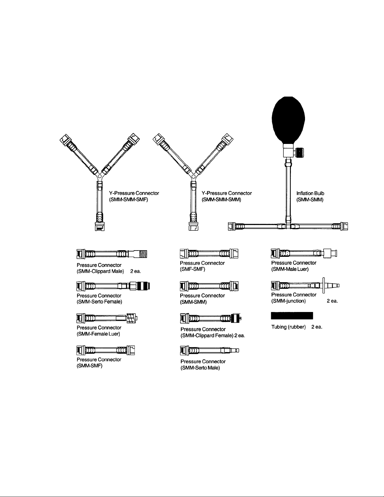
Appendix A – Tubing Kit Components
A-1
Page 52

This page intentionally left blank.
B-2
Page 53

Appendix B - Schematics
QA-1290 Schematic Diagram Part 1 (Top Level) .......................................................................B-2
QA-1290 Schematic Diagram Part 2 (Power)............................................................................... B-3
QA-1290 Schematic Diagram Part 3 (I/O)....................................................................................B-4
QA-1290 Schematic Diagram Part 4 (Stepper Motor Driver) ......................................................B-5
QA-1290 Schematic Diagram Part 5 (A/D Converter) ................................................................. B-6
QA-1290 Schematic Diagram Part 6 (Pressure Sensor and Amplifier) ........................................ B-7
QA-1290 Schematic Diagram Part 7 (Component Notation - Top Side)......................................B-8
QA-1290 Schematic Diagram Part 8 (Component Notation - Bottom Side)................................ B-9
C-1
Page 54

B-2
Page 55

B-3
Page 56

B-4
Page 57

B-5
Page 58

B-6
Page 59

B-7
Page 60

B-8
Page 61

B-9
Page 62

This page intentionally left blank.
B-10
Page 63

USA
1345 Monroe NW, Suite 255A
Grand Rapids, MI 49505
Phone: (+1) 888 863-8766
Fax: (+1) 616 454-3350
E-mail: support.us@metron-biomed.com
FRANCE
30, rue Paul Claudel
91000 Evry, France
Phone: (+33) 1 6078 8899
Fax: (+33) 1 6078 6839
E-mail: info@metron.fr
NORWAY
Travbaneveien 1
N-7044 Trondheim, Norway
Phone: (+47) 7382 8500
Fax: (+47) 7391 7009
E-mail: support@metron.no
From: (name) Phone:
Address: Fax:
E-mail:
Date:
Error Report
Product: Version: Serial no.:
Description of the situation prior to the error:
Description of the error:
(METRON AS internally)
Comments:
Received date: Correction date: Ref No. Critical Normal Minor
C-1
Page 64

USA
1345 Monroe NW, Suite 255A
Grand Rapids, MI 49505
Phone: (+1) 888 863-8766
Fax: (+1) 616 454-3350
E-mail: support.us@metron-biomed.com
FRANCE
30, rue Paul Claudel
91000 Evry, France
Phone: (+33) 1 6078 8899
Fax: (+33) 1 6078 6839
E-mail: info@metron.fr
NORWAY
Travbaneveien 1
N-7044 Trondheim, Norway
Phone: (+47) 7382 8500
Fax: (+47) 7391 7009
E-mail: support@metron.no
From:
Phone:
(name)
Address: Fax:
E-mail:
Date:
Improvement Suggestion
Product: Version:
Description of the suggested improvement:
(METRON AS internally)
Comments:
Received date: Correction date: Ref No. Critical Normal Minor
D-1
Page 65

USA
1345 Monroe NW, Suite 255A
Grand Rapids, MI 49505
Phone: (+1) 888 863-8766
Fax: (+1) 616 454-3350
E-mail: support.us@metron-biomed.com
FRANCE
30, rue Paul Claudel
91000 Evry, France
Phone: (+33) 1 6078 8899
Fax: (+33) 1 6078 6839
E-mail: info@metron.fr
NORWAY
Travbaneveien 1
N-7044 Trondheim, Norway
Phone: (+47) 7382 8500
Fax: (+47) 7391 7009
E-mail: support@metron.no
.
 Loading...