

Page 1
ENGLISH
EV CHARGING STATION
USER MANUAL
Page 2
About
Information about charging stations and the
latest version of this document is available at
www.eauto.si/metron-shop
To contact METRON, call +386 51 320 538
or write us an e-mail on info@euato.si
ILLUSTRATIONS
The illustrations provided in this document are for demonstration purposes only. Depending on charging
station options and market region, the information may appear slightly different.
PRODUCT SPECIFICATIONS
All specifications and descriptions contained in this document are verified to be accurate at the time of
printing. However, because continuous improvement is a goal at METRON, we reserve the right to make
product modifications at any time. To communicate any inaccuracies or omissions in this document,
please send an email to: info@eauto.si
2018 METRON, d.o.o.
All information in this document is subject to copyright and other intellectual property rights of METRON,
d.o.o. and its licensors. This material may not be modified, reproduced or copied, in whole or in part, without the prior written permission of Metron, d.o.o. and its licensors. Additional information is available upon
request.
Page 3

Contents
About………………………………………………..2
General……………………………………………………….2
Safety…………………………………………………………..2
Intended use…………………………………………………………….2
Qualification of personnel……………………………………….3
Product description……………………………………3
Optional equipment…………………………………………………4
Identification plate……………………………………………………4
Exterior And Interior View……………………………………….5
General Data……………………………………………………………..6
Maximum Cable
Cross-Section At Terminals………………………………………7
Ambient Conditions………………………………………………….7
Installation…………………………………………8
Choice Of Location…………………………………………………..8
Unpacking…………………………………………………………………9
Opening The Charging Station……………………………….9
Minimum Distances…………………………………………………10
Installing The Charger Station
On The Wall………………………………………………………………11
Electrical connection……………………..12
Voltage Supply /
Supply Network Connection………………………………….12
Safeguarding And Personal Protection…………………12
Connecting The Supply Line………………………………….13
Operation………………………………………..14
Dynamic Power Control…………………………………………14
How To Set The Charging Station Part 1……………………15
1st Group – Current Setting…………………………………….15
2nd Group – Main Household Fuse Type………………..16
3rd Group – On-board
Charger Response Time…………………………………………16
How To Set The Charging Station Part 2…………………..16
Example 1…………………………………………………………………17
Example 2………………………………………………………………..18
Re-activating The Residual Current
Circuit Breaker And Circuit Breaker…………………………..19
Charging the vehicle……………………………………………….19
Mode 3 Charging……………………………………………………20
Terminating The Charging Process……………………….20
Status LED………………………………………………………………..20
Maintenance……………………………………21
Maintenance Plan……………………………………………………21
Troubleshooting…………………………….22
Disassembly, Storage
and Disposal…………………………………..23
Disassembly…………………………………………………………….23
Storage…………………………………………………………………….23
Disposal……………………………………………………………………23
Warranty…………………………………………24
Limited Warranty…………………………………………………….24
Returning Devices…………………………………………………..24
Page 4

About
2
EV Charging station user manual
General
This manual is an important aid for ensuring the fault-free and safe operation of the device. The specifications in this manual apply only to the device stated in the product description. Read this manual before
setting up the device.
Using this manual will help you to:
• avoid any risks for the user
• become acquainted with the device
• achieve optimum functioning
• promptly detect and rectify faults
• avoid any malfunctions due to improper installation
• cut down on repair costs and reduce the number of downtimes
• improve the reliability and increase the service life of the system
• avoid causing harm to the environment
These instructions are an important part of the product and must be retained for future reference. METRON
accepts no liability for any damage resulting from non observance of the information in this manual.
Safety
The device has been designed using state-of-the-art technology and is safe to operate.
Nevertheless, there may be residual risks associated with the device under the following circumstances:
• the device is not used as intended
• non-compliance with the safety information given in this manual
• the device is damaged
• the device is not maintained properly
• the device is modified or converted improperly
• the maintenance work specified in this manual is not carried out in due time
Warning: Risk of death resulting from non-compliance with documentation! Any person authorized
to work on the system must have read and understood this manual, in particular the “Safety” chapter.
The electrical installation, initial operation and servicing of the device may only be performed by qualified electricians who have been authorized by the operator.
Intended Use
The device may be used for the purpose described in “Product Description” on page 3 and in conjunction with the supplied and approved components. Any use exceeding the aforementioned shall be
deemed unintended. METRON assumes no liability for damage resulting from non-intended use. Intended use also includes:
• compliance with all the information in this manual;
• carrying out of servicing tasks according to schedule.
The device may present hazards, if not used as intended.
Page 5

About
3
EV Charging station user manual
Qualification Of Personnel
The electrical installation, setup and maintenance of the device may only be performed by qualified electricians, which have received authorization from the system operator to perform such tasks. Such persons
must have read and understood the operating manual and must comply with the information therein.
Requirements of qualified electricians:
• knowledge of general and special safety and accident prevention guidelines;
• knowledge of relevant electrical guidelines (e.g. DIN VDE 0100 section 600 DIN VDE 0100722), as
well as valid national regulations;
• the ability to recognize risks and avoid possible dangers.
Product Description
METRON range of charging stations (Nano, Standard
and Duo) is unique for its robustness and durability
with close to zero maintenance. It is designed to
charge electric vehicles and is supplied either with
a type 2 socket or on cable Type 2/Type 1 plug with
various charging power capabilities. Nano charging
station also has an option of advanced dynamic
power control.
The METRON charging station is meant to be used in private and semi-public areas, such as company car
parks, depots or private land.
The charging station is used exclusively for charging electrically powered vehicles.
• Mode 3 charging according to IEC 61851-1:2010.
• Plugs and sockets according to IEC 62196.
The charging station is operated as a stand-alone solution without connection to a master control system. The charging station is intended solely for fixed installation.
Features:
• Status information through LED
• METRON charging station communication and control unit EVSE
• Push button for setting current
• Steel made enclosure
• Wired ready for connection
Page 6
About
4
EV Charging station user manual
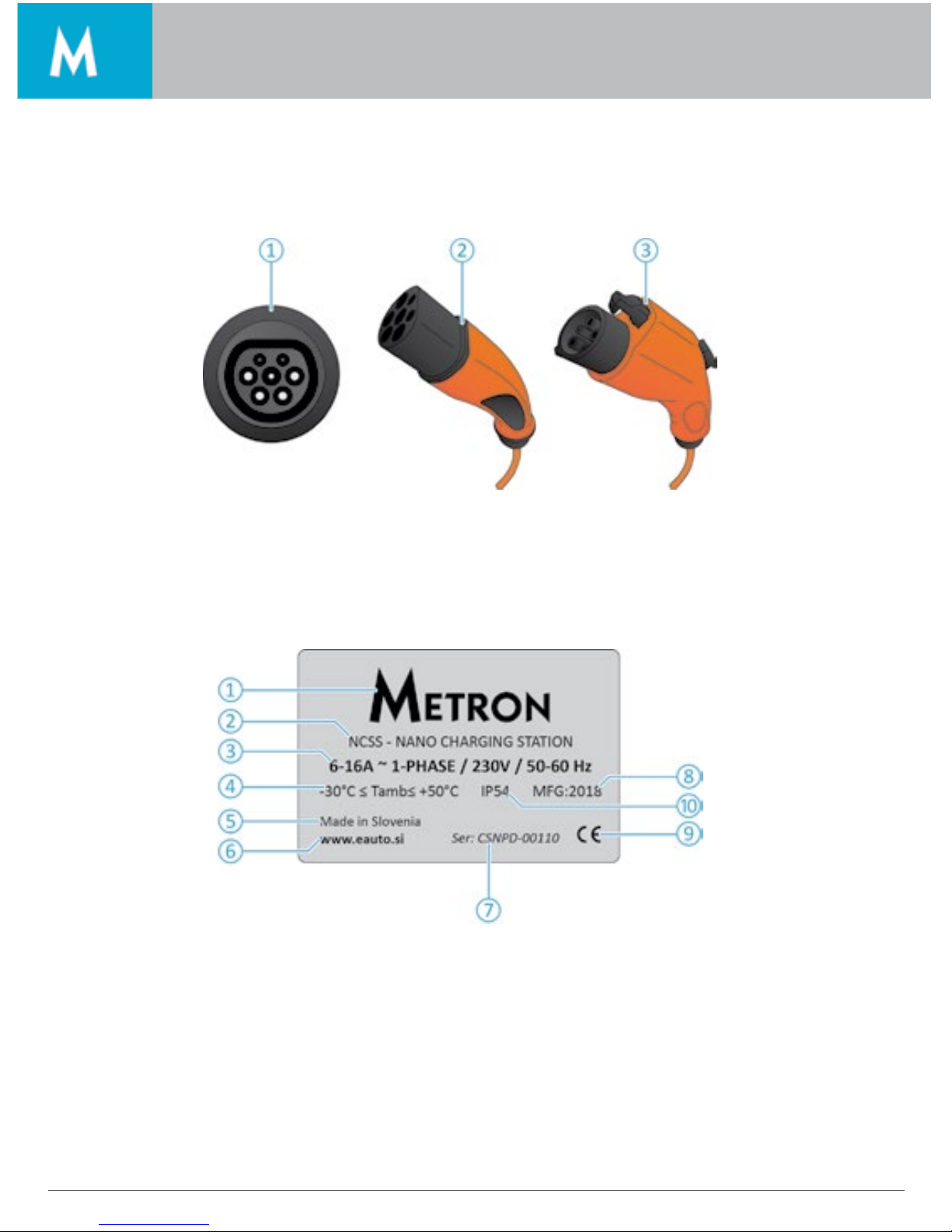
Optional Equipment
Depending on the version, the charging station is equipped with one of the following connector systems:
1. Charging socket Type 2 for Mode 3 charging.
2. Permanently connected charging cable with charging connector Type 2.
3. Permanently connected charging cable with charging connector Type 1.
Identification Plate
1. Manufacturer
2. Type
3. Grid connection and current setting
4. Temperature operating range
5. Country of origin
6. Web page
7. Serial number
8. Protection class
9. Year of production
10. Certification mark
Page 7
About
5
EV Charging station user manual
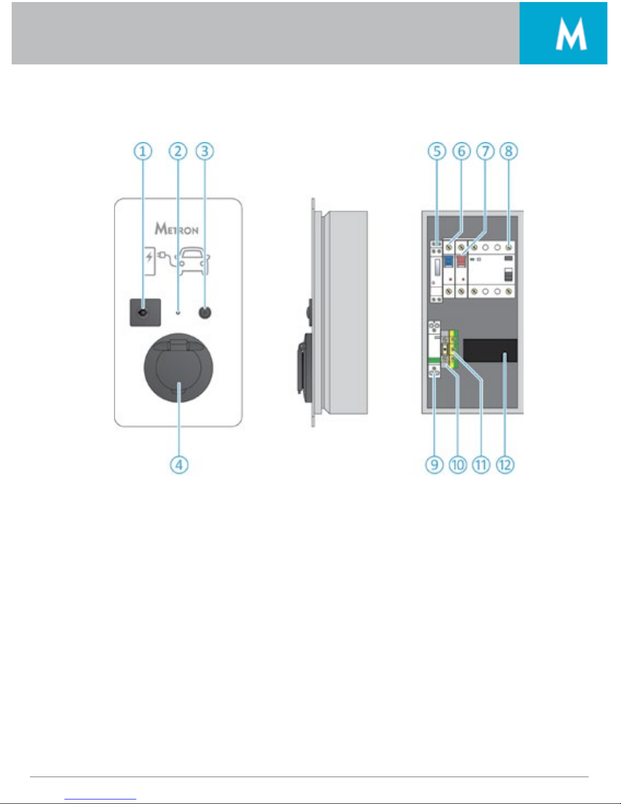
Exterior And Interior View
1. Lock
2. LED light
3. Push button
4. Socket
5. kWh counter
6. Charging cable fuse
7. Charge control fuse
8. RCCB
9. Circuit braker CB
10. CP terminal
11. Terminal earth
12. charge controler
Page 8
About
6
EV Charging station user manual
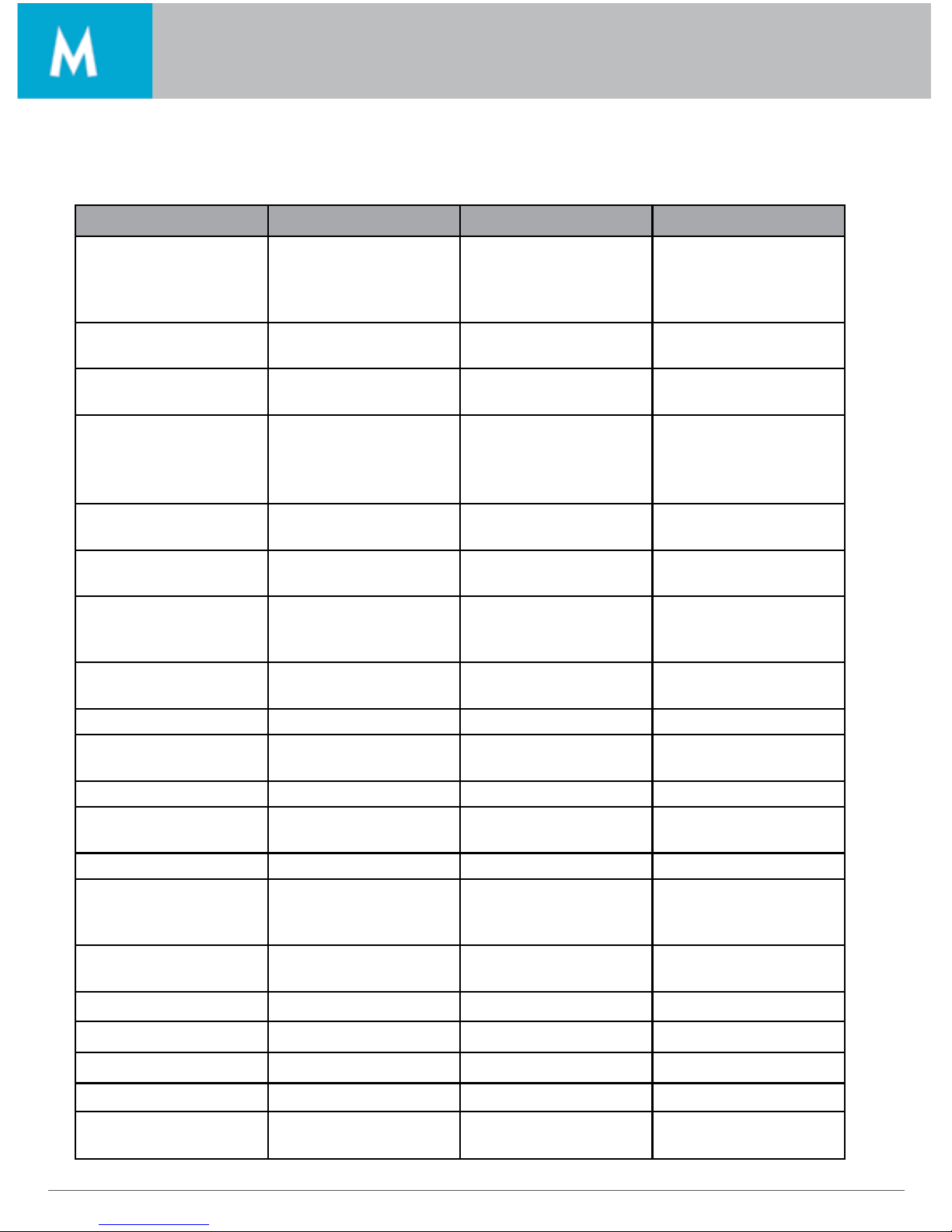
General Data
Nano Standar Duo
Charging station plug/
socket type
Type 2 / Type 1 (IEC
62196 / SAE J1772)
female plug or type 2
charging socket
Type 2 (IEC 62196)
female plug or charging
socket
Type 2 (IEC 62196)
female plug or charging
socket
Required power cable 3G2,5 mm2 for 3, 7 kW 5G2,5 mm2 for 11 kW
5G6 mm2 for 22 kW
2x5G2,5 mm2 for 11 kW
2x5G6 mm2 for 22 kW
3G6 mm2 for 7,4 kW 5G2,5 mm2 for 11 kW 3x16 A / 11 kW or 3x32 A
/ 22 kW*
Min: 2 sockets 1x16A and
Max: 2 sockets 3x16A *
5G6 mm2 for 22 kW 2x5G2,5 mm2 for 11 kW 6/8/10/13/16 A or
6/8/10/13/16/20/25/32
A**
6/8/10/13/16 A**
2x5G6 mm2 for 22 kW 3,7 kW or 7,4 kW
(1-phase)
11 kW or 22 kW
(3-phase)
11 kW (3-phase)
Max. charging current 16 A / 3,7 kW or 32 A /
7,4 kW *
3x16 A / 11 kW or 3x32 A
/ 22 kW*
Min: 2 sockets 1x16A and
Max: 2 sockets 3x16A *
Possible charging current settings
6/8/10/13/16 A or From 155 V to 470 V
(3-phase) (50/60 Hz)
From 90 V to 270 V (1phase) or from 155 V to
470 V (3-phase) (50/60 Hz)
6/8/10/13/16/20/25/32
A**
5m*** 5m*** 5m***
6/8/10/13/16 A or Yes Yes
6/8/10/13/16/20/25/32
A**
Yes Yes Yes
6/8/10/13/16 A** Optional Optional
Max. charging power 3,7 kW or 7,4 kW
(1-phase)
11 kW or 22 kW
(3-phase)
11 kW (3-phase)
Rated Voltage 230 Vac 230 Vac/400 Vac 230 Vac/400 Vac
Operating voltage/frequency range
From 180 V to 270 V
(50/60 Hz)
From 155 V to 470 V
(3-phase) (50/60 Hz)
From 90 V to 270 V (1phase) or from 155 V to
470 V (3-phase) (50/60 Hz)
Cable length (if ordered
with plug and cable)
5m*** 5m*** 5m***
Circuit breaker Yes Yes Yes
Type A RCD protection Yes Yes Yes
Type B RCD protection Optional Optional Optional
UV resistance Yes (all parts) Yes (all parts) Yes (all parts)
Operating ambient air
temperature range
From -30°C to +50°C From -30°C to +50°C From -30°C to +50°C
Page 9
About
7
EV Charging station user manual
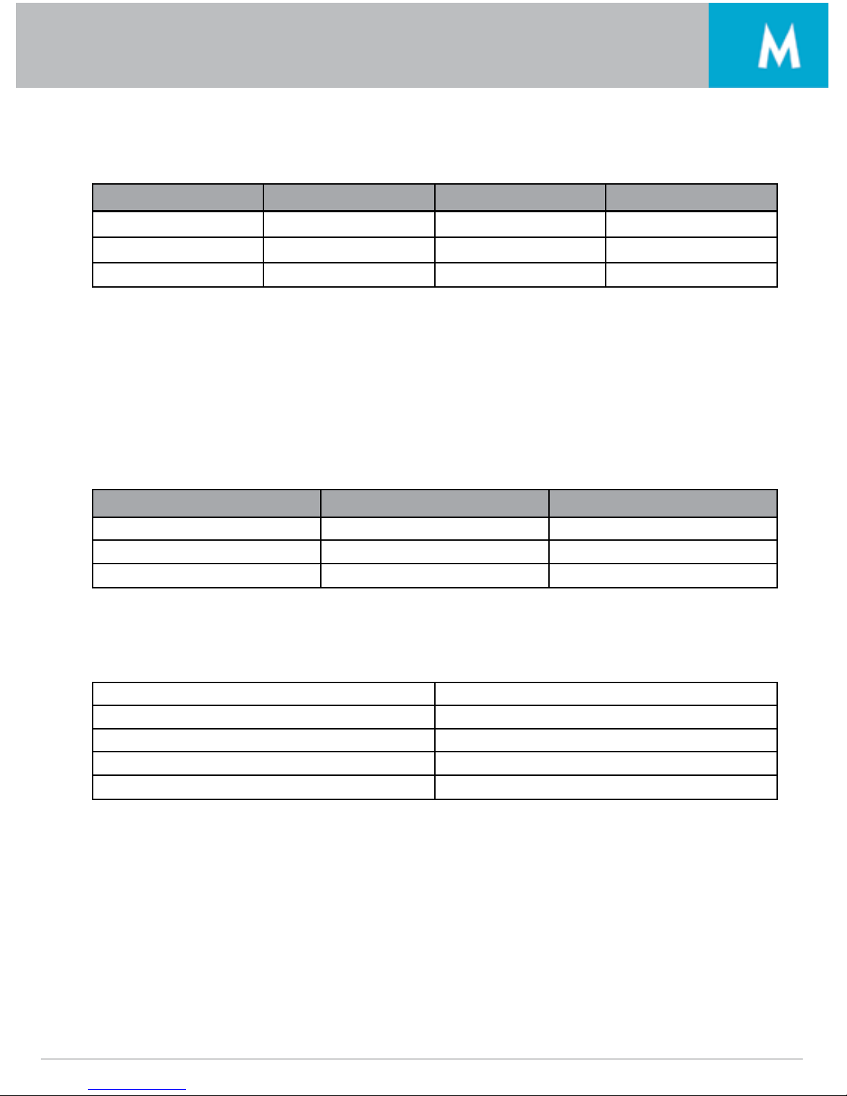
Nano Standar Duo
IP Rating IP54 IP54 IP54
Weight App 8-10 kg App 8-10 kg App 10-12 kg
Dynamic power control Optional No No
*Exact max charging power and configuration information can be found on the product information
label, which is located on the right hand side of the charging station.
**Charging current setting is based on the order and only customers that need max 32A/phase can set
the charging current above 16 A.
***Cable length is based on the order.
Maximum Cable Cross-Section At Terminals
Power Rigid Flexible
3.7 kW 3 x 6 mm2 3 x 4 mm2
7.4 kW 3 x 10 mm2 3 x 6 mm2
11 kW 5 x 6 mm2 5 x 4 mm2
Ambient Conditions
Ambient temperature -25 to +40 °C
Average temperature over 24 hours < 35 °C
Storage temperature Altitude -25 to +40 °C
Altitude max. 2,000 meters above sea level
Relative humidity max. 95 % (non-condensing)
Page 10
8 Installation
Installation
Warning: Mortal danger posed by improper installation. There is a risk of injury for persons performing tasks for which they are neither qualified nor have received appropriate training.
• The device may only be installed by personnel which are familiar with the task, have been instructed
with regard to the associated hazards and who possess the necessary qualifications.
• Before installing, all safety requirements must be met.
Choice Of Location
Warning: Risk due to unsuitable environmental conditions / installation locations. Unsuitable ambient
conditions and installation locations may lead to dangerous situations when dealing with electricity.
Please observe the following points when selecting an installation location:
• Do not install in potentially explosive atmospheres (e.g. gas refueling stations).
• Do not install in flood-prone areas.
• Comply with local technical connection requirements and safety rules.
• For ambient conditions, see Chapter “Ambient conditions” on page 7.
• The charging system must be protected from direct exposure to water jets.
• The mounting surface must have sufficient strength to withstand the mechanical stresses. When
mounting on plasterboard walls they must have at least two layers.
Page 11

9Installation
Installation
Unpacking
Caution: Damage to the charging station by improper handling.
Collisions and impacts may damage the charging station.
• Move the charging station with caution.
• Use a soft base to set aside the charging station
1. Charging station
2. User manual
3. Warranty
4. Bag with installation hardware (screws, dowels)
5. Key
Opening The Charging Station
1. Insert the key into the hole
2. Rotate the key clockwise
3. Key should be facing upwards when unlocked
4. Open the wicket to the right
Page 12
10 Installation
Installation
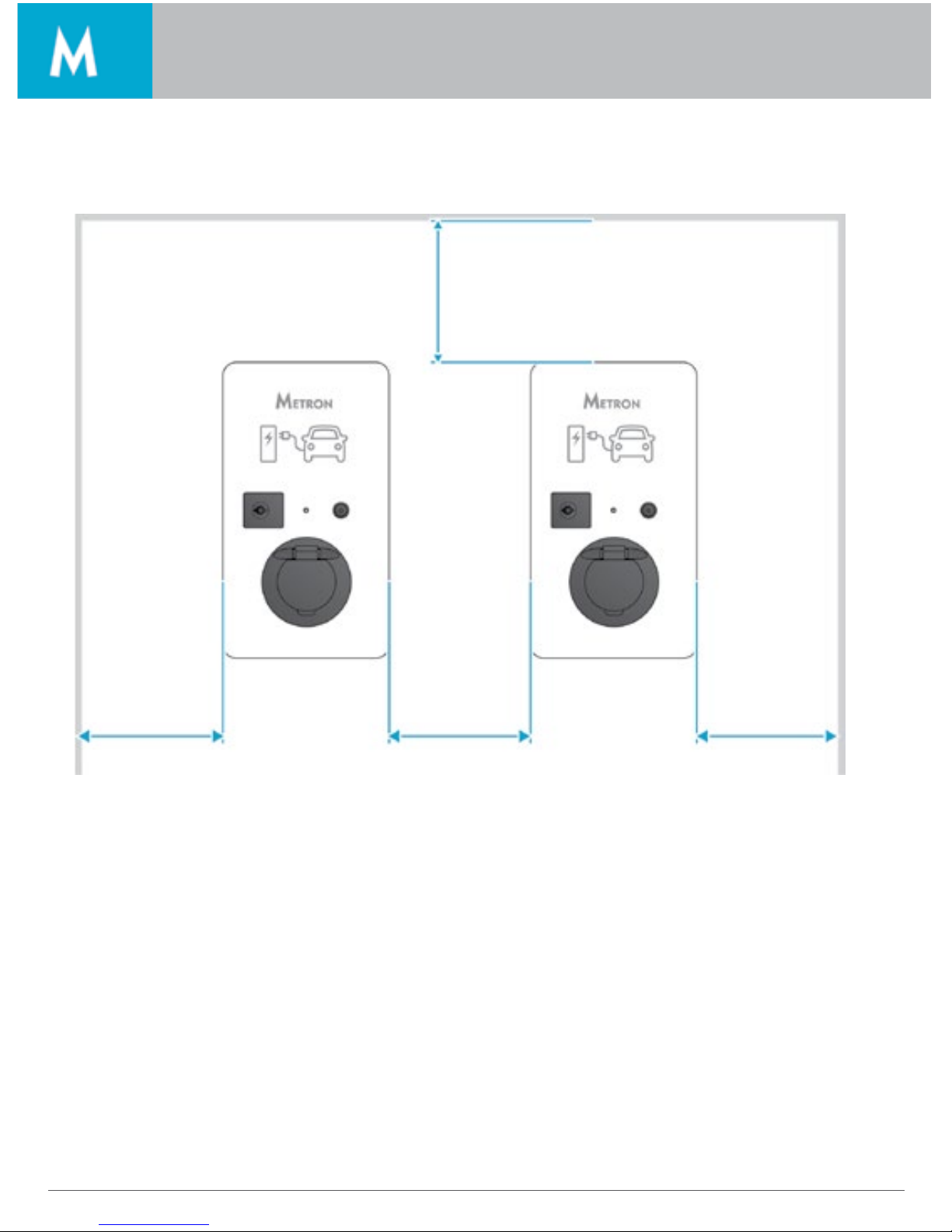
Minimum Distances
Maintain the specified minimum distances for unrestricted access during operation, maintenance and
repair. The dimensions are given in mm.
300 300 300
300
Page 13

11Installation
Installation
Installing The Charger Station On The Wall
For installation on concrete, brick and wood walls, use the included installation hardware. For other surfaces, a suitable on-site mounting method must be chosen.
METRON recommends the installation of the charging station at a height (up to the top edge of the enclosure) of approximately 1.50 meters above the finished floor.
1. Mark the mounting holes
2. Drill the holes in the wall
3. Secure the charging station to the wall by using dowels and screws
Check the charging station for firm and secure fit.
A
Nano 260 mm
Standard 260 mm
Duo 360 mm
B
Nano 110 mm
Standard 130 mm
Duo 260 mm
1. Dowels
2. Screws
Page 14
12 Electrical connection
Electrical connection
Voltage Supply / Supply Network Connection
Warning: Risk of death by electric shock! Components have voltage applied. Contact with current
conducting parts results in an electric shock, burns or death. When working with the electrical
system, the following points must be observed:
• Disconnect device from voltage
• Secure device from being turned back on
• Ensure that no voltage is applied
• Earth and short-circuit the unit
• Cover neighboring components that are under voltage and secure the danger area
Note the following points when connecting to the power supply:
• Observe the application national/local regulations;
• Ensure a clockwise rotating field for a three-phase connection.
Safeguarding And Personal Protection
Warning: Danger to life by electric shock. Residual current circuit breakers (type B) sensitive to
universal currents may be installed instead of residual current circuit breakers (type A) sensitive to
pulse currents. Depending on the equipment package, the charging stations are fitted with the
required safety equipment
Note the following points when connecting the charging station:
• Each charging station must be connected using a separate residual current circuit breaker (residual
current circuit breaker type A for single-phase versions, residual current circuit breaker type B for
three-phase versions).
• No other circuit may be connected to this residual current circuit breaker
• Design of the on-site circuit breaker
Warning: Fire hazard due to device overload.
Fire hazard due to device overload in case of wrong design of the on-site circuit breaker.
The normal current of the selected circuit breaker must not exceed the specifications on the
nameplate.
Page 15

13Electrical connection
Electrical connection
Connecting The Supply Line
1. Strip the supply cable over a length of 370 mm and remove the core insulation over a length of 12 mm
2. Connect the cores of the supply cable to the RCCB ① and the earth core to the terminal ②
The protective earth conductor ③ must be longer than all other conductors
3. Check that the individual cores are properly connected and that the screws are tightened
4. Turn the reset leaver ④ to position 1 to power the system
Page 16

14 Operation
Warning: Mortal danger posed by improper installation. There is a risk of injury for persons performing tasks for which they are neither qualifies nor have received appropriate training.
Operation
Warning: Risk of injury
There is a risk of injury due to damage to the charging system.
If it appears that, the charging system cannot be operated safely:
• Take the charging system out of service.
• Determine and eliminate any faults / malfunctions.
• Contact your electrician, local dealer or direct factory help
Dynamic Power Control
This is an advanced function that protects the main
household fuse, which is installed on the phase
that your electric vehicle is using for charging. For
this to function you have to install a current sensor
on the line (L1, L2 or L3) that comes from the main
household fuse and then connect this sensor to
the charging station. The maximum length of the
current sensor connecting cable is 40 m. We recommend that you use shielded 8 core UTP cable
and use 4 wires as one wire.
The function of dynamic power control has three
groups of settings, which are set with the push button (see chapter “How to set the charging station
on page 15):
Caution: When the charging station receives power supply
(connection to the grid) the LED blinks 5 times.
Page 17

15Operation
Operation
How To Set The Charging Station Part 1
1. Press and hold the push button (LED switches off
immediately)
2. After 5 seconds LED starts blinking slowly
3. Releasing the push button after a certain number
of blinks determines the setting (see example on
page 17)
Important: If after 5 or 8 blinks (depending on the charging station) you do not release the push
button for another 30 seconds, the system will take you to the next setting which enables you to set
the main household fuse type. The setting begins automatically when the LED starts to blink again.
1st Group – Current Setting
This setting enables you to set the maximum charging current
with which your electric vehicle, will be charging.
Nano 3,7 kW Nano 7,4 kW
Number
of blinks
1 2 3 4 5 6 7 8
Charging
current/power
6 A
1,4 kW
8 A
1,8 kW
10 A
2,3 kW
13 A
3,0 kW
16 A
3,7 kW
20 A
4,6 kW
25 A
5,8 kW
32 A
7,4 kW
Standard 3,7 kW Standard 7,4 kW
Number
of blinks
1 2 3 4 5 6 7 8
Charging
current/power
3x6 A
4,1 kW
3x8 A
5,5 kW
3x10 A
6,9 kW
3x13 A
9,0 kW
3x16 A
11,0 kW
3x20 A
13,8 kW
3x25 A
17,4 kW
3x32 A
22 kW
Page 18

16 Operation
Operation
Duo 11 kW Duo 22 kW
Number
of blinks
1 2 3 4 5 6 7 8
Charging
current/power
2x3x6 A
2x4,1 kW
2x3x8 A
2x5,5 kW
2x3x10 A
2x6,9 kW
2x3x13 A
2x9,0 kW
2x3x16 A
2x11,0 kW
2x3x20 A
2x13,8 kW
2x3x25 A
2x17,4 kW
2x3x32 A
2x22 kW
2nd Group – Main Household Fuse Type
With this setting, you set the amperage of the main household fuse on which your car will be connected.
For more information on the type of the main household fuse, please contact your grid operator. The
default value is set to 16 A.
Number of blinks From 1 to 40 (each blink signals 1 Ampere)
Fuse type From 1 to 40 A
Caution: If after 40 blinks you do not release the push button for another 30 seconds, the system
will take you to the next setting which enables you to set the on board charger response time.
The setting begins automatically when the LED starts to blink again.
3rd Group – On-board Charger Response Time
This setting defines the on-board charger reaction time. Most of the chargers can change the current
every 2 seconds. This setting does not need to be changed since the default value is set to 2 seconds.
Warning: Risk of serious damage if done incorrectly. Performed only by expert who is qualified
and have received appropriate training.
How To Set The Charging Station Part 2
Since these settings are in consecutive order, the first setting you need to perform is the “On-board charger response time” (not necessary). Once you do that, you have to start again to set the “Main household
fuse type” and at the end, you can set the desired “Charging current” (See example on the next page).
Page 19

17Operation
Operation
1. Press and hold the push button (LED switches off immediately);
2. After steps:
• 5 LED blinks
• 30 seconds
• 40 blinks
• 30 seconds, you will enter in the 3rd Group;
3. Releasing the push button after 5th blink determines the setting.
STEP 2
Next is main household fuse type.
Example 1:
Let say we want the following specifications for our charging station:
• Current Setting = 16 A
• Main household fuse type = 32 A
• On-board charger response time = 5 seconds
STEP 1
First, you need to set the on-board charger response time.
1. Press and hold the push button (LED switches off immediately);
2. After steps:
• 5 LED blinks
• 30 seconds, you will enter in the 2rd Group;
3. Releasing the push button after 32nd blink determines the setting.
Page 20

18 Operation
Operation
STEP 3
Next is main household fuse type.
1. Press and hold the push button (LED switches off immediately);
2. Releasing the push button after 5th blink determines the setting.
Example 2:
For this example, we want the following specifications for our charging station:
• Current Setting = 20 A
• Main household fuse type = 25 A
• On-board charger response time = 2 seconds
In this case we can skip the setting for “On-board charger response time” because the default setting
is already set to 2 seconds (unless you have changed it with previous setting).
STEP 1
Set the main household fuse type.
1. Press and hold the push button (LED switches off immediately)
2. After steps:
• 5 LED blinks
• 30 seconds, you will enter in the 2nd Group;
3. Releasing the push button after 25th blink determines the setting.
Page 21

19Operation
Operation
STEP 2
Set main household fuse type.
1. Press and hold the push button (LED switches off immediately);
2. Releasing the push button after 6th blink determines the setting.
Important: The dynamic charging control will maintain the desired charging current until the over-
all load on the line is greater than setting of the main household fuse type. Then it will every 1-5
seconds reduce the charging current until it is within the safe limit.
Re-activating The Residual Current Circuit Breaker And Circuit Breaker
To reset the residual current circuit breaker (RCCB) ① and circuit breaker (CB) ② you must open the
charging station and manually restart them. Reset lever ③ should be in position 0. Turn in to position 1 to
power the system. System is re-activated and charging station is operational again.
Charging the vehicle
Warning: Risk of injury due to incorrect handling!
Using an extension cable or second charging cable may result in electric shock or cable fire. Using
extension cables is not permitted.
• Never use more than one charging cable for connection the electric vehicle to the charging station.
• Use only undamaged charging cables.
Page 22

20 Operation
Operation
Mode 3 Charging
Make sure that vehicle and charging cable are suitable for mode 3 charging.
1. Connect the charging cable to the vehicle.
2. Insert the plug of the charging cable completely into the charging socket type 2 at the charging
station (only for charging stations with integrated charging socket type 2).
The charging station performs now the following steps automatically:
• Detecting the current-carrying capacity of the charging cable with resistance coding. Unsuitable
charging cables are rejected.
• It checks that the requirements for proper charging have been met.
• Communicating with the vehicle using the CP contact. The charging current upper limit is communi-
cated to the vehicle with a PWM signal. The protective earth connection is checked at the same time.
• The vehicle signals the charging station that it is ready for charging. The charging process starts.
• The status LED slowly blinks.
• The maximum available charging current depends on the following points:
-Power rating of the charging station.
-Features / version of the charging station.
-Current load capacity of the charging cable.
Terminating The Charging Process
Caution: To terminate the charging process we recommend that you interrupt the charging with
your vehicle FOB key or any other vehicle key that stops the charging. We do not recommend that
you unplug the cable from the station during the charging.
Status LED
The status LED displays the operating status/faults of the charging station. See Troubleshooting chapter
on page 22 for more information.
Page 23

21Maintenance
Maintenance
Warning: Risk of death resulting from improper maintenance / repair.
There is a risk of injury for persons performing tasks for which they are neither qualified nor have
received appropriate training.
• The maintenance / repair of the device may be performed only by persons who are familiar with
this task, have been instructed with regard to the associated hazards and who possess the necessary qualifications.
• All technical safety conditions have to be satisfied prior to performing maintenance / repairs.
Warning: Risk of death by electric shock!
Components have voltage applied.
Contact with current conducting parts results in an electric shock, burns or death.
When working with the electrical system, the following points must be observed:
• Disconnect device from voltage.
• Secure device from being turned back on.
• Ensure that no voltage is applied.
• Earth and short-circuit the unit.
• Cover neighboring components that are under voltage and secure the danger area.
Maintenance Plan
Caution: Carry out the following maintenance work at the specified intervals.
Maintenance interval every 6 months (biannually).
Part / Component Maintenance Work
Enclosure Visual inspection for defects or damage.
Check the device for secure fastening.
Clean the outside of the enclosure with damp cloth.
Front panel Visual inspection for defects or damage.
Switching and safety devices Visual inspection for defects or damage.
Check the function of the circuit breaker (CB). See Re-activating
the residual current circuit breaker and circuit breaker on page 19.
Caution: Maintenance interval every four years.
In addition, carry out all maintenance specified in Maintenance interval every 6 months (biannually).
Part / Component Maintenance Work
Cable connections and connectors Visual inspection for defects or damage.
Charging station Visual inspection for defects or damage.
System check Check function
Ask a qualified electrician to check the system according to
VDE0100.
Page 24

22 Troubleshooting
Troubleshooting
Warning: If you cannot rectify the error or fault, ask a qualified electrician to check the charging station.
Problem Cause Fix
LED is not blinking. There is no power to the charging
station or EVSE, the LED is faulty or
EVSE is faulty
Check the activation of CB or
RCCA, check EVSE fuse. Otherwise, send the product to service.
Slow blinking when plug
is unplugged
Indicating previous saved current
setting
No fix needed.
Constantly on when plug
is unplugged
Stand-by / Ready to charge No fix needed.
Slow blinking when plugged in Charging No fix needed.
Constantly on when plugged in Electric vehicle fully charged No fix needed.
Slow blinking 2 times when
plug is plugged in
Electric vehicle requests interior
ventilation (charging is stopped)
Wait for the vehicle to cool down.
Slow blinking 3 times when
plug is plugged in
Charging station overheated
(charging is stopped) system
restarts charging automatically
when it cools down
Wait for the charging station to
cool down. Change the position
of the charging station.
Rapid blinking (plugged
or unplugged)
Fault Send the station to service center.
Slow blinking when plug
is unplugged
Indicating previous saved current
setting
No fix needed.
Page 25

23Disassembly, Storage and Disposal
Disassembly, Storage and Disposal
Disassembly
Warning: Risk of death by electric shock!
Components have voltage applied.
Contact with current conducting parts results in an electric shock, burns or death.
When working with the electrical system, the following points must be observed:
• Disconnect device from voltage.
• Secure device from being turned back on.
• Ensure that no voltage is applied.
• Earth and short-circuit the unit.
• Cover neighboring components that are under voltage and secure the danger area.
Ask your installer to remove the charging station.
Storage
The storage spaces must be dry and temperature regulated. See chapter “Ambient conditions” on page 7
for ambient storage conditions.
Disposal
The disposal of old devices must comply with the common national and regional laws and regulations.
Ecological considerations must be taken into account.
Old devices and batteries cannot be disposed of with household rubbish.
• Dispose of the device in accordance with the applicable environmental regulations of your country.
• Dispose of old devices through your specialized dealer.
• Dispose of old batteries in a recycling bin for old batteries or through the specialized dealer.
• Dispose of the packaging material in the recycling bin for cardboard, paper and plastic.
Page 26

24 Warranty
Warranty
In the event of complaints regarding the product, please contact your responsible service partner
immediately and provide the following information:
• type designation / serial number
• date of manufacture
• reason for complaint
• duration of use
• ambient conditions (temperature, humidity)
Limited Warranty
METRON warrants its product to the original consumer purchaser that it will repair or replace any product that
is deemed defective for the following terms: One (1) year from date of purchase on all components.
To be eligible for repair or replacement under this warranty, the product in question must be sent back to
METRON within the warranty period and the original consumer purchaser must comply with the following
conditions:
• The product thereof must not have been modified or altered in any way by an unauthorized source.
• The product thereof must have been used in accordance with the user manual.
This limited warranty does not cover:
• Damage due to improper use;
• Damage done by incorrect setting;
• Accidental or intentional damage;
• Misuse, abuse, corrosion, or neglect;
• Product impaired by severe natural conditions, such as excessive hail storms, lightning strikes, torna-
does, flooding, ice or other natural occurrences;
• Damage due to improper packaging on return shipment.
Any and all labor charges for troubleshooting, removal or replacement of the product are not covered
by this warranty.
All shipping costs regarding repair or replacement of the product is to be pre-paid by the customer.
Returning Devices
In case you return the device to METRON for repair, please use the original packaging or a suitable, safe transport container.
Page 27

Page 28

 Loading...