

Page 1

MANUAL FOR MODEL FD4 FIRE PUMP CONTROLLERS
Firmware version 5.02
This manual provides General Information, Installation, Operation, Maintenance and System Set-Up Informati on for METR ON Model
FD-4 Engine Driven Fire Pump Controllers.
TABLE OF CONTENTS
PART I General Information ........................................................................................................................................ PAGE 3
PART II Functions ......................................................................................................................................................... PAGE 3
PART III Operation of the Controller ............................................................................................................................. PAGE 4
PART IV Installation & Test Procedure ......................................................................................................................... PAGE 5
PART V Additional Optional Features ......................................................................................................................... PAGE 9
PART V I Opera t o r I nt e r f a c e D e v i c e ( OID) Use and Navigation ........................................................................ PAGE 10
PART VII System Set Point Definitions ........................................................................................................................ PAGE 18
PART VIII Alarm and Event Log Messages ................................................................................................................... PAGE 22
PART IX SD Card File Format .................................................................................................................................... PAGE 25
Appendix A Modbus Protocol ........................................................................................................................................... PAGE 29
METRON, INC.
Hubbell Industrial Controls Inc.
4301 Cheyenne Drive, Archdale, NC 27263
www.metroninc.com
Telephone: (336) 434-2800 Ext. 183
Metron, Inc. Date: 03/22/04 Approved: MH DOC#: 586
Revision: P
Date: 03/15/15 Approved: RA Page: 1 of 34
Page 2

THIS PAGE IS BLANK
Page 2 of 34
File Name: Doc#586p.docx
Page 3

PART I: GENERAL INFORMATION
The basic function of the model FD4 Fire Pump Controller for diesel engine driven fire pumps is to automatically st art the engi ne
upon a drop in pressure in the water main, or from a number of other demand signals. This controll er provides aut omatic cycl ed
cranking, alarm and/or alarm shutdown protection for various engine failures. Stopping of the engine afte r the demand peri od is over
may be either manual or automatic. This controller also includes an automatic weekly test starting feature.
QUICK START FEATURE
The quick start feature prompts the user to set up quickly the essential screens for correct use of this fire pump controller. This
feature is initiated by pressing and holding the ‘3 PILOT push button for 2s. Then the following screens will be required to be
completed in the following order:
Start pressure Stop pressure Delay start Time
Date Weekly start time Weekly start day Commissione d date
Double skinned fuel tank Electronic Engine.
PART II: FUNCTIONS
Equipment is provided in the Controller to provide the following functions:
A. Automatic Starting From:
a. Drop in water line pressure
b. Loss of bat tery charger output (i f enabled)
c. Operation of optional remote start switches, such as remote start switch, deluge valve switch, fire alarm switch, etc.
d. Weekly test timer
B. OID – Operator Interface Device - Provided for display of alarm functions, system pressure, battery volts, battery charger amps,
alarm conditions, etc. Includes a 4 line by 20 character LCD for display of system messages and program mi ng.
C. Auto-Off-Manual selector switch.
D. Automatic Cranking - A microprocessor controlled crank cycle timer provides six (6) fixed crank periods separated by five (5)
rest periods each of approximately 15 seconds duration.
E. Alarms and Signal Lights – Twenty Two (22) Standard lights are provided to give visual signals for; "System Fault”, "Battery
#1 Healthy”, Battery #2 Healthy", "Charger #1 Failure", Charger #2 Failure”, “AC Power Loss”, “Engi ne Running”,
"Engine Failed to Start", "Engine Low Oil Pressure", "Engine High Water Temp", "Engine Overspeed", “Low Fuel”,
”ECM Failure”,”ECM Warning”,ECM Sw.in Alt.”, ”ECM Injection Fault”, “Fuel Tank Leak”,”Clogged Wate r
Strainer”,“High Cooling Water Temp”, “Low Engine Temp”, ”Contactor Coil Failure”, and “Pump On Demand”. In
addition the mode buttons have LED’s on the button indicating “Auto”, Manual ”, “Test”, or “Off” mode. 2 additional lights,
configurable by the factory, can be provided for "Pump Room Alarms". An audible alarm horn is mounted on the front of the
cubicle for sounding in the event of failure. Terminals are provided for remote failure indication of the following:
"Automatic Mode"
"System Fault"
"Engine Running (2 sets)"
"Common Battery Fault"
First Out Annunciation
This feature can be turned on via screen 313. The STND is no first out alarm sequence.
F3A: This feature when turned on, will make the first alarm to occur fast flash, then all subsequent alarms slow flash. A first out
reset input is required, to clear the first alarm (Pilot pushbutton currently). Pressing the mute pb will turn all slow flashin
to steady, First out alarm will slow flash.
F1A This feature when turned on, will make the first alarm to occur flash, then all subsequent alarms will show steady. A first
out reset input is required (Pilot pushbutton currently), to clear the first alarm. Pressing the mute pushbutton will silence the
mutable alarms, First out alarm will be on steady.
g alarms
Page 3 of 34
File Name: Doc#586p.docx
Page 4

F. A data logger is provided as standard to record system pressure along with numerous alarm conditi ons and syst em events. The
data can be displayed on the OID or can be downloaded to a PC through the RS485 port provided o n the m ain system board.
Data is stored on an SD Memory card. This card contains individual pressure files with each file containing one days worth of
pressure data. Each file is of the PressXXX.txt format. Each entry is stamped with the date and time and system pressure at that
time. The Events.txt file contains all of the logged events with each event stamped with date and time. The SD memory card can
be removed and files transferred directly to a PC using appropriate memory card reader. The controller will continue to operate
normally with the SD card removed. There will, however, be a visual and audible alarm when the card is removed. Events and
pressure data will continue to be logged while the card is missing. The memory cards should be replaced within 12 hours to
ensure that no data is lost.
G. A weekly test timer is supplied to automatically start the engine any set day of the week, at a set time of day, and a preset run
time. See Part IV below for more information and the System Config Screen 106.
H. "Stop" Pushbutton - A pushbutton is provided to stop the engine in Auto at any time provided all starting demands have
cleared. This returns the controller to the automatic position. The Auto-Off-Manual selector switch can also be put in the “Off”
mode to stop the engine. Any starting commands will not start the engine in the “Off” mode.
I. Integral Battery Chargers (Option J). There are two separate fully automatic, solid state chargers provided for maintaining full
charge on the dual sets of engine batteries. An LED display is provided on each charger to indicate charger AC input voltage is
present and DC output voltage is present.
User Preferences Screen 218 and 219 are used to determine when the Charger Failure alarm will activate. When Screen 218 is
set to No, the Charger Failure alarm will not be active while the engine is running. Should both chargers fail or switch off due to
a high voltage output from the engine alternator, the AC Power Failure lamp may come on. This is normal. It will reset
automatically once the engine stops running and the charger failure alarms reset. When Screen 218 is set to Yes, the Charger
Failure alarm will be active at all times when the Mode selector switch is in the Auto or Manual mode. Screen 219 is used to
determine the time delay between the failure contacts on the charger closing and the Charger Failure lamp and audible alarm
sounding on the controller.
J. Cabinet - A heavy gauge steel cubicle encloses the controller. The OID, the key operated Auto-Off-Manual (AOM) Selector
Switch and manual start pushbuttons are mounted on the outer door. The battery circuit breakers are located inside the cabinet on
the main back panel of the unit. A key for the AOM switch is stored in a break-glass housing on the door of the cabinet. An
additional key is located inside the cabinet.
PART III: OPERATION OF THE CONTROLLER
A. When the controller is the "Auto" mode and both circuit breakers are in the "On" position, the controller is in standby
condition ready to start the engine automatically. A green pilot light above the "Auto" button will illuminate in this mode.
Also, Battery #1 Fault and Battery #2 Fault lights should be off indicating that battery power is availabl e.
When the water pressure drops below a level which is set in System Config Screen 101, the Control ler will actuat e the starter
motor and the cranking cycle will commence. In addition the “Pump on Demand” light will illuminate. If the engine starts and
runs, cranking will cease and the protective circuits will be operative. If the engine fails to start after six (6) crank periods,
cranking will cease, the "Engine Failed to Start" light will illuminate, and the alarm horn will sound. The fuel solenoid will
stay on for one hour however. This is to allow the engine to continue to run in the event the failed to start condition was due
faulty speed switch signal from the engine. The battery alternating circuit alternates batteries on each crank attempt unless one
battery is in a discharged state and incapable of cranking the engine. In this instance, the control will lock onto the other battery
for the remaining cranking attempts. Dry contacts for rem ote indicat ion of "Battery Failure" are provided.
The panel is wired so that optional remote start switches may be used, such as Deluge Valve, Remote Start pushbutt on, External
Pressure , These start switches will also cause the “Pump on Demand” light to illuminate.etc. In addition, when “Power
Failure Engine Startup” feature is enabled (System Config Screen 111), the Controller will automa ticall y start the engi ne upon
loss of Battery Charger output or AC Power loss, after an adjustable time delay (System Config Screen 112).
While the engine is running, all protective circuits are operative. If the engine stops whi le running, an d there is still an a ut o st a rt
demand, the control will attempt to restart the engine. If the engine fails to start the "Engine Failed to Start" light will
illuminate and the alarm will sound. If, while the engine is operating, the oil pressure drops bel ow a safe limit, the “Low Oil
Pressure” light will illuminate immediately. After approximately seven (7) seconds the alarm will sound. Should the engi ne
temperature exceed a safe limit while running, the “Engine High Water Temp.” light will illuminate after a seven (7) second
time delay and the alarm will sound indicating engine overheating.
to a
Page 4 of 34
File Name: Doc#586p.docx
Page 5

In case of Overspeed, the engine will be stopped and the "Engine Overspeed" light will illuminate and the alarm will sound.
The light and alarm will stay on until the Engine Speed Switch and the Controller are manually reset. To manually reset the
Controller, turn the controller selector switch to Off, then press the Reset button. Then turn the selector switch back to “Auto”.
The Controller may be configured as either "Manual" or "Automatic" stop as required (System Config Screen 104).
"Manual" stop is set as standard. The current status of this setting is visible on the Main System Status Screen where the letter
“A” will appear in the upper right hand corner of the screen when set to Automatic Stop and an “M” will appear when set for
Manual stop. When Automatic stop is enabled the stop timer is preset at the fact ory to 30 m inutes. Longer tim e settings can be
set in System Config screen 105 with a maximum setting of 60 minutes possibl e. When “Automatic Stop” is di sabled, the
engine will continue to run even though the pressure switch or other rem ote starting switch returns t o its norm al positi on. The
engine can be stopped immediately only by pressing the stop button or by turni ng the Auto-Off-M anual swi tch to the Off
position. On engines that do not use the “energize to stop” method (i.e. Caterpillar), the engine may also be stopped by t urni ng
the circuit breakers BATT1 and BATT2 to OFF. If set up for "Automatic" stop, the engine will be stopped aut omati cally upon
restoration to normal of whatever demand switch started the engine providing i t has run at least 30 minut es or longer as set in
System Config screen 105. If the demand period was less than the time set on the auto st op timer, the engine will conti nue to
run until the timer times out and then will stop.
B. When the "Test" mode button is pressed for two or more seconds, t he engine wi ll be st arted by causi ng a drop in water
pressure. Failure alarm circuits will be operative in the "Test" mode. This method of starting provides a test of the Controller,
thereby assuring proper operation when required. The engine will run for the time set in Auto Weekly Test Lengt h Of Run Tim e
(System Config Screen 109) or until the "Stop" push button is pressed or the selector switch is turned to “OFF”.
C. The "Manual" position of the Auto-Off-Manual switch is for manually starting the engine from either battery. The fuel and
water solenoids are energized in this position, and the engine must be cranked by pushing one of the butt ons located below the
OID. "Manual Crank 1" cranks from Battery 1, and "Manual Crank 2" cranks from Battery 2. Pressing both buttons will
result in cranking from both batteries simultaneously.
D. When the engine is given a command to stop for any reason, terminal 12 will energize and will remain on for approximately 15
seconds. The controller will not start until terminal 12 is de-energized again.
E. Periodic Self Testing - The Test Run Timer can be set to give test runs on any day of the week and time of day desired. A
timing element is incorporated in the control so that when the engine starts in this manner, it will run for a definite time before it
shuts down. See System Config Screens 106 through 109 to set the starting tim e and lengt h of engine runni ng.
F. Provision for sequential starting is accomplished by the use of adjustable time delay on pressure drop starting or “Deluge Valve”
starting. On Multiple Pump installations these timers are set sequentially and progressively longer in tim e to prevent more th an
one (1) pump from starting simultaneously with another pump. Fai lure of the lead pum p to start will not prevent subsequent
pumps from starting. The time delay on starting is set in System Config Screen 103.
G. The “Pump On Demand” alarm light is provided to indicate that there is a command to start and run the additive pump
controller. This includes a low pressure condition, deluge valve start signal etc. The alarm light will clear when the start
condition has been cleared such as the water pressure in the system rises above the high set point set in screen 102.
H. The “Contactor Coil Failure” alarm light is to annunciate a loss of continuity to the two engine starting contactors on the engine.
There is a low level DC current that is applied to field terminals #9 and #10 to detect conti nuity in the contactor coils. Shou ld the
contactor coil open or fail, the “Contactor Coil Failure” LED will illuminate and the alarm horn will sound. In addition there will
be an entry in the Event log to indicate which Contactor coil has failed.
I. The “Loss of DC Power” lamp is provided to indicate that both batteries have been disconnected or turned off but AC po wer is
still available. The alarm horn will also sound upon the loss of DC Power and can not be silenced.
J. The “ECM Failure”,”ECM Warning”,“ECM Sw. in Alt.” and “ECM Injection Fault” alarms apply only to those engines that
have electronic fuel control. Should the Electronic Engine Control Module detect a problem, the appropriate alarm LED will
illuminate and sound the horn.
PART IV: INSTALLATION AND TEST PROCEDURE
A. INSTALLATION
The Fire Pump Controller has been assembled and wired at the factory in accordance with the highest workmanship st andards.
All circuits and functions have been thoroughly tested to assure correct operation when properly installed. The installer should
be completely familiar with the external hookup of the engine junction box t o the te rminal bar in the Control le r. Various engi ne
components must be wired to the proper terminal in the controller using the correct size of stranded wire. An appropri ate size
Page 5 of 34
File Name: Doc#586p.docx
Page 6

wire must be wired from the grounding lug in the controller to earth ground. In m ost cases, t he engine manufacturer furn ishes
the engines with all accessories installed and wired to the connection box. Therefore, it is only necessary to wire from the
engine connection box to like numbered terminals in the Controller. Note proper wire sizes. All wires must be stranded.
A drain valve is provided to relieve water pressure to the pressure switch, thus closing the pressure switch contacts and starting
the engine. This test simulates an actual start demand. Since the Controller operates the drain valve only momentarily, a small
amount of water is drained off. The water pressure sensing line to the Controller from the pump must be thoroughly flushed
before connection to the Controller in order to remove chips, particles, or other matt er, that coul d enter t he plumbing
components in the Controller.
Controllers configured with "Automatic Stop" enabled may be changed to "Manual" stop by disabling this feature in Syst em
Config Screen 104. If deluge valve switches are to be used for starting, enable the Deluge Valve Option in Config Screen 121
and connect the remote normally closed switch to terminals 31 and 111.
B. TEST PROCEDURE
All of the following tests should be made on each unit after installation. If each test is satisfactory, the operator may place the
control switch in "Auto" mode and depend upon the panel operating properly when requi red. Also, any one or all of t hese test s
may be carried out at any time after installation, if so desired. NOTE: If 115 Volts A.C. is not connected to Controller, the
"Charger Failure" lights and “AC Power Loss” light and alarm will be activated and if the Power Failure Start feature
(System Config Screen 111) is enabled, the controller will start automatically. The 115VAC must be turned ON to
prevent the engine from starting.
ENGINE TERMINAL (terminals 1-12) STATUS INDICATOR LIGHTS
Light Emitting Diodes (L.E.D.) lights have been installed on the microprocessor module to indicate the status of each engine
terminal. Status indication is given bel ow:
Terminal Number
L.E.D. (light) "ON" Indication
(Microprocessor Func #)
1 (Out 06) Power available to fuel and water solenoids
2 (In 06) Speed switch has operated into engine running mode
3 (In 07) Speed switch has operated into overspeed mode
4 (In 08) Oil Pressure switch contacts closed (Low Oil Pressure)
5 (In 09) Water temperature switch contacts closed (High Engine Temp.)
6 (In 01) Battery #1 voltage present
8 (In 02) Battery #2 voltage present
9 (Out 02) Crank #1 voltage present (while cranking on Bat t e ry #1)
10 (Out 03) Crank #2 voltage present (while cranking on Bat t ery #2)
12 (Out 07) Energize to stop voltage present
a. BATTERY LOCKOUT TEST:
1. Turn on Battery #1 switch and Battery #2 switch.
2. Press the "Reset" button. Battery #1 and Battery #2 Healthy lights should be on.
3. Turn Battery #1 switch off for a couple of seconds and back on. Battery #1 light should go off and remain off.
4. Press "Reset" button. Battery #1 light should come on.
5. Repeat for Battery #2.
b. CRANKING CYCLE TEST: This test simulates a condition where the engine refuses to start.
1. Disconnect Terminal No.1 on Controller panel. NOTE: Disconnecting Terminal No.1 is for the purpose of
removing power from the fuel solenoid so engine will not start. On engines where the fuel solenoid is not used
(Caterpillar), or is connected other than through Terminal #1 (Clarke-G.M.), other means must be used to
stop fuel flow to the engine to prevent starting.
2. Press the "Test" mode button to start cranking the engine. Time the crank and rest periods, and count the num ber of
cranks. There should be six (6) crank periods separated by five (5) rest periods each of approximately 15-seconds
Page 6 of 34
File Name: Doc#586p.docx
Page 7

duration. The "Failed to Start" light should come on and the alarm horn should sound. St atus indi cator li ght for
Terminal #1 should come on as soon as the "Test" push button is pressed and the pressure drops below the low set
point. Indicator lights for terminals 9 and 10 should come on alternately to indicat e cranking cycle. (See above)
3. Press the "Stop" push button to stop the engine and properly reconnect all leads.
NOTE: In order to prevent discharging the starting batteries, this same test can be made without actually
cranking the engine by disconnecting the starter cable and observing the action of the starter contactors
and/or status indicator lights for terminals 9 and 10.
c. CHECKING STARTING MOTOR RELEASE
1. Press the “Test” mode button. Engine should start promptly and starting motor should release at approximat ely 1/3 of
engine speed. Status indicator light for terminal #2 should come on to indi cate speed swit ch has operated t o disconnect
cranking and the Engine Running LED should illuminate.
NOTE: A convenient method of determining the exact instant the starter releases is to connect a battery test li ght or
voltmeter across the starter terminals and observe when power is disconnected.
2. Press the “Stop” push button to stop the engine.
d. OIL PRESSURE FAILURE TEST:
1. Press the "Test" mode button to start engine. When the engine is starting and oil pressure i s not yet up t o full pressure,
the "Engine Low Oil Pressure" light will illuminate, but the horn will not sound. When pressure builds up, and the
switch opens, the light will go out. This feature provides indication that the oil pressure switch contacts are operating
in a normal manner.
Note: On Electronic Engines with electronic oil pressure sensors, the oil pressure light may not illuminate while the
engine is cranking. The low oil pressure test should be performed on these engines with the engine running as described
below.
2. After the engine is running, connect a temporary jumper between terminal #4 and terminal #11.
3. Both the "Engine Low Oil Pressure" light and status indicator light for terminal #4 should come on immediately.
Wait approximately seven (7) seconds. Alarm horn should sound.
4. Press the "Stop" push button to stop the engine and remove jumper between terminal #4 and terminal #11.
5. Wait at least 30 seconds for elements to reset before making any further tests.
e. WATER TEMPERATURE FAILURE TEST:
1. Press the "Test" push button to start engine.
2. Jumper contacts on water temperature switch on engine.
3. Alarm horn sounds and the "High Water Temperature" light on controller will illuminate after approximately 7
seconds. Status indicator light for terminal #5 should come on with "High Water Temperature” l i ght .
4.
Press the "Stop" push button to stop the engine and remove jumper on water switch.
f. OVERSPEED FAILURE TEST:
1. Press the "Test" mode button to start engine.
2. Momentarily short the contacts on the engine speed switch, or connect a temporary jumper between terminal #3 and #6
on the controller.
3. The alarm horn sounds and the "Engine Overspeed" light will illuminate immediately. Engine comes to a stop.
Status indicator lights for terminals #3 and #12 should come on with t he "Engine Overspeed" light .
4. Remove the jumper from terminals #3 and #6 then turn the selector switch to the Off position. Press the "Reset"
button to reset the “Overspeed” alarm. Turn the selector switch back to the Auto position.
g. CONTACTOR COIL FAILURE ALARM TEST:
1. While the controller is in the "Auto" mode disconnect the field wire from terminal 9. Within a few seconds the
"Contactor Coil Failure” lamp should illuminate and the alarm horn should sound. Reconnect the field wire to
terminal 9. The "Contactor Coil Failure” lamp should go out and the alarm horn should silence. Repeat for terminal
10.
Page 7 of 34
File Name: Doc#586p.docx
Page 8

h. AUTOMATIC STARTING TESTS:
1. Place control in "Auto" position.
2. Bleed off pressure in system until pressure drops below the low set point. The “Pump on Demand” light should come
on.
3. Engine should start automatically and continue to run after pressure rises above the high set point, if arranged for
"Manual" stop. If arranged for "Automatic" stop, engine will continue to run for time set on Engi ne Run Tim er and
then stop.
4. Press the "Stop" push button to stop the engine.
5. Repeat tests for each demand switch such as deluge valve, remote start, etc.
i. PERIODIC WEEKLY START TEST:
1. Pressure must be up and all other demand switches de-activated.
2. 115 V.A.C. power must be turned on to the panel.
3. When the current day and time of day matches the settings in System Config screens 107 and 108, the solenoid drain
valve will energize and the engine will begin cranking. It will continue to run for the amount of t ime set.
4. Should a remote manual start occur or a low pressure condition occur while the pump is running on Weekly Test, the
pump will not stop until the Stop pushbutton is pressed or if set for Automatic Stop, the Minimum run timer times out.
5. The periodic Weekly Test function is factory set to No in Screen 106 due to Factory Mutual standard requirements.
Contact the Metron Factory Service department for instructions to turn this functi on on if thi s is not a Fact ory Mutual
insured facility.
j. SETTING PROGRAM WEEKLY TEST TIME: System Config screen 106 through 109.
k. REMOTE START SWITCH CIRCUITS: Field wiring terminals are provided on the controller so that optional remote
start switches such as Remote Pushbutton Stations, Deluge Valve Switch, Fire Alarm Switches, etc., may be used to start
the engine. Two (2) sets of terminals are provided. Terminals #112 and #31 are used for remote manual start push buttons
(close to start). Terminals #111 and #31 are used for remote Deluge Valve Switch or other remote automatic start switches
(open to start). Upon automatic start from this type of switch, the engine will be stopped either automati cally (if set for
automatic stop) after the demand switch de-activates and Engine Auto Stop Tim er tim es out, or m anually at t he Controller.
Terminals #111 and #31 must have a jumper installed if a remote Deluge switch is “Enabled” but not to be used. When t he
controller is shipped from the factory Deluge Valve start is Disabled (System Config screen 121).
l. AC POWER FAILURE STARTING: If this feature has been enabled it can be tested by disconnecting the normal 115
V.A.C. to the Controller. After the preset time delay (which is specified in Sy stem C onfig screen 112), t he Control ler will
commence cranking the engine. The "Charger #1 Failure”, “Charger #2 Failure”, and “AC Power Loss" lamps will
illuminate and the alarm will sound without delay.
m. NORMAL OPERATION – AUTOMATIC: Turn the selector switch to the “Auto" position. A green "Automatic
Mode" light will illuminate and the engine will automatical ly start upon d rop in pressure or operat ion of other st art
switches. If the Auto Stop Timer is disabled (Manual Stop) the engine must be turned off at the Controller. When t he Auto
Stop Timer is enabled, upon termination of the demand signal , the engine will run for the lengt h of tim e left on t he Auto
Stop Timer and then will stop automatically.
n. AN ADJUSTABLE SEQUENTIAL START TIMER IS SUPPLIED FOR MULTIPLE PUMP INSTALLATION:
Normally, the leading pump Controller will not have a delay timer and will commence cranking t he engine imm ediately
upon operation of a demand signal (other than Power Failure which is time delayed). The subsequent Control lers will have
a time delay which is adjustable from 0 to 999 seconds. Each time delay should be set with progressively longer tim es on
each subsequent pump. The recommended time interval is ten (10) to fifteen (15) seconds. This may be extended or
shortened as required by the local authorities having jurisdiction.
o. PUMP ROOM ALARMS: Field terminals may be provided for various inputs from pump room alarms. These alarms
include: Low Fuel, Low Pump Room Temperature, Reservoir Low, Reservoir Empty, Low Suction Pressure, Relief Valve
Discharge and/or Flow Meter On etc. A maximum of ten (8) pump room alarms are available. The Cont roller is arranged so
that the alarm horn will sound and the light will come on when the alarm sensor contacts close. These pump room alarms
can be silenced with the “Silence” push button on the OID if they have been configured as silenceable.
Page 8 of 34
File Name: Doc#586p.docx
Page 9

p. FOAM PUMP OPTION: An optional feature to operate an external pressure dump valve can be provided for Foam Pump
Service if required. Screen 318 is set to approximately 10-15 seconds to operate a dry contact which can be used to operate
the Dump Valve solenoid. This contact will close when a demand for the pump to run is received such as low pressure,
deluge valve, remote start, weekly test start etc. Once the engine is runni ng, the tim ing circuit will start and keep the conta ct
close for the length of time set in screen 318. Then it will open and de-energize the dump valve allowing the pump to
develop full pressure. In addition, if the controller is not activated by a pressure start, the pressure transducer can be
deactivated through screen 319. This will also remove the pressure display from the main status screen of the OID. The
controller can only then be activated by a remote start such as deluge valve or remote start contacts. This a factory settable
option only and must be ordered with the controller before it ships from the factory.
PART V: ADDITIONAL OPTIONAL FEATURES
A. Battery Charger Operation: The Battery Chargers are mounted in the engine controller, and are factory wired to the controller
terminal block from which it obtains its 120 volt, 50-60 Hz. suppl y vol tage, and throug h whi ch it provi des charging current to
the batteries. The charging current to the two (2) batteries and the battery voltage is monitored by the controller and displayed
on the OID. The charger output is current limited and provides full protection duri ng the engi ne cranking cy cle. The charger
input and output are fused for protection in case of a failure of the control circuit or other i nternal component.
Each battery charger is fully automatic, and will charge the batteries at a rate of up to 10 amperes. As the batteries approach full
charge, the current will taper off to a predetermined level at which time the charger automatically switches to the float mode of
operation. In the float mode the charger maintains the batteries at the float potential (approximately 12.7 volts for a 12-volt
battery or 25.4 volts for the 24-volt battery).
The charger provides a means of monitoring the charger output to sound an alarm in case of loss of charger output. This also
provides a means of monitoring the A.C. power since a loss of A.C. power results in a loss of charger output.
Never disconnect the batteries from the controller while the AC power is on to the controller as this may cause damage
to the printed circuit boards.
In the event that a battery is lost or disconnected the output of the charger will stop (0 vol ts). Thi s will allow the vol tage sensing
circuit of the fire pump controller microprocessor to detect a missing battery or open circuit from the batt ery. This will result in
the respective Battery Fault light to illuminate and the alarm horn to sound. Before reconnecting the battery to the controller,
turn the AC power off. Then reconnect the battery to the controller and turn the AC power back on.to reset the alarm.
Generally, when all conditions are normal, the batteries will come to a full charge prior to the 24 hour period. As batteries begin
to charge, the controller OID will indicate a gradual decrease in current flow. When these ammeters indicate a current level of
less than 0.5 amps the charger will be in a trickle mode.
Check batteries daily for a few days after initial installation has been made, and weekly thereafter. Batteries should be checked
for overcharging (gassing), or undercharging (low voltage, or low specific gravity of the elect rolyte or acid.
CAUTION: Under no circumstances should new electrolyte (acid) be added to a battery that has been previously filled.
Only distilled water is recommended for maintenance purposes.
Page 9 of 34
File Name: Doc#586p.docx
Page 10
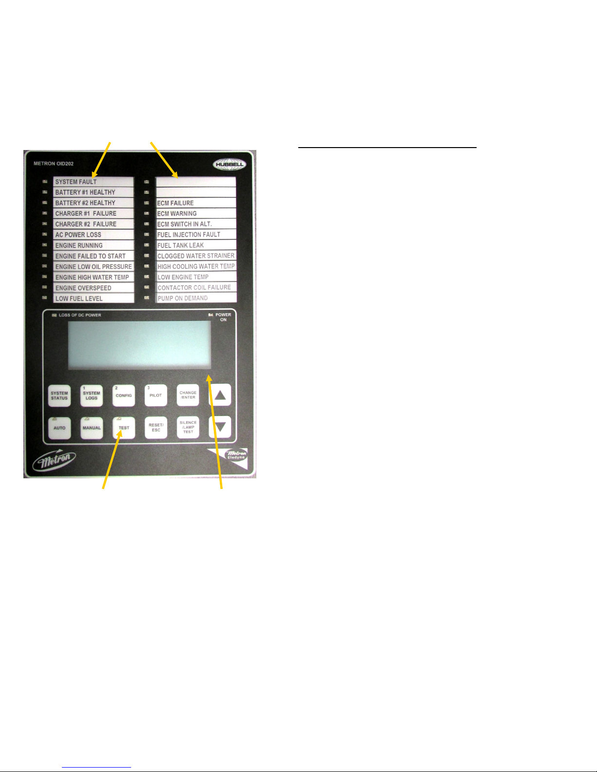
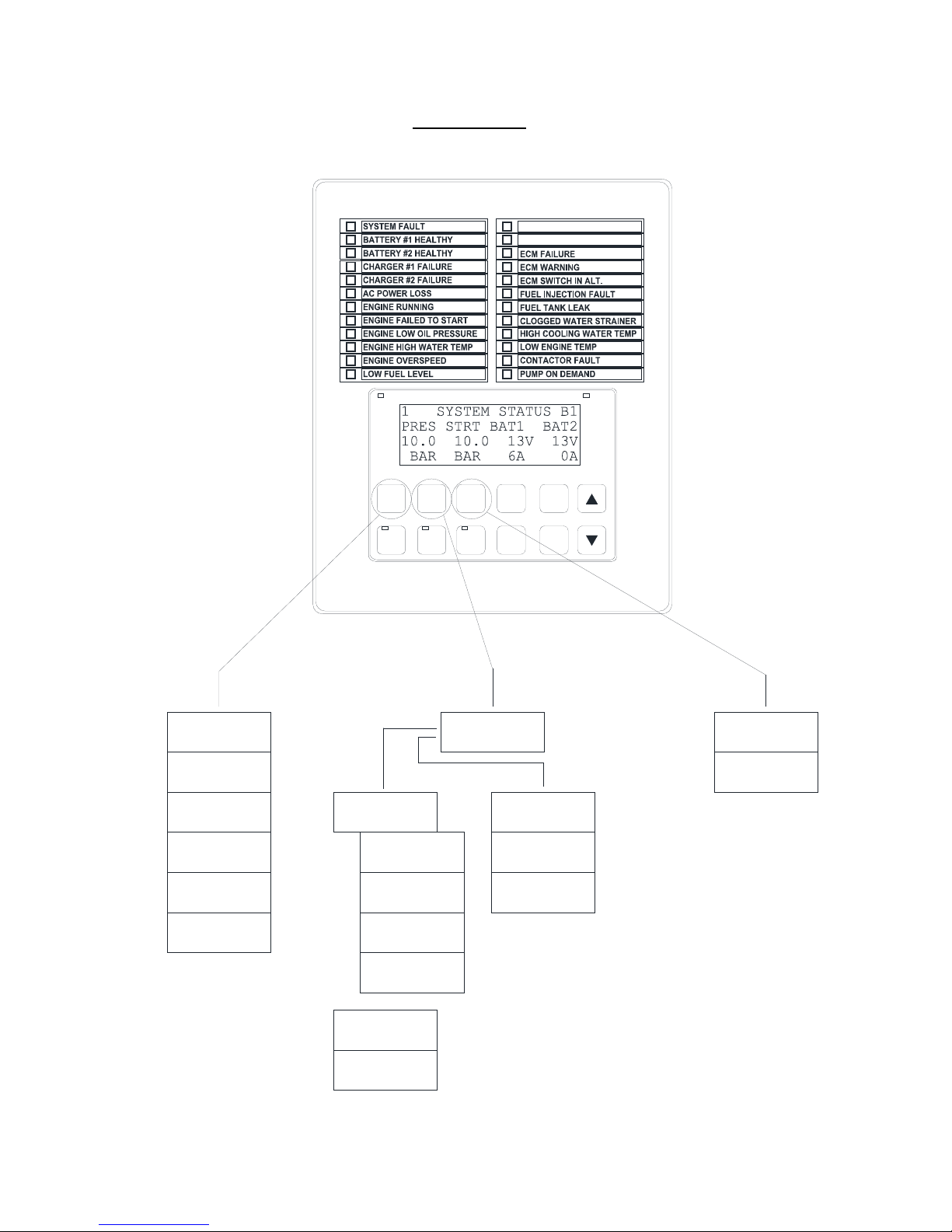
PART VI: OPERATOR INTERFACE DEVICE (OID) USE AND NAVIGATION
The Operator Interface Device (OID) provides visual indication of the alarms, status of system parameters, and an interface to
change set points to configure the FD4 to operate appropriately for various installation requirements.
Labeled LED
Annunciator
Common Tasks Performed Using The OID
Silencing Horn: If a horn is sounding and the alarm is silence
able, a quick press of the [SILENCE/LAMP TEST] will silence the
horn (less than 1 second press).
Resetting Alarms: If the alarm condition has cleared, press and
hold the [RESET/ESC] button 2 to 5 seconds to reset alarms.
“Engine Failed to Start” and “Engine Overspeed” alarms require
the system to be in the OFF mode before a reset is allowed.
Test Mode: When controller is in Auto Mode, pressing and
holding the [TEST] button for two or more seconds will open the
pressure drain solenoid thus dropping the pressure which causes
the controller to start the engine. Pressing and releasing the
[TEST] button in Manual Mode will illuminate the lamp on the
button but has no effect on the starting.
Lamp Test: To illuminate and check all the OID LED’s and the
horn, press and hold the [SILENCE/LAMP TEST] button 5 or
more seconds or until all the lights turn on. The lamps will cycle
on for 2 seconds and off for 2 seconds.
System Operation and Digital Display With
Control Type Buttons Navigation Buttons
Sample display only. For general reference only.
Page 10 of 34
File Name: Doc#586p.docx
Page 11
METRON OID202
OID Screen Map
LOSS OF DC POWER
1
SYSTEM
SYSTEM
STATUS
LOGS
AUTO MANUAL TEST
2
CONFIG
POWER
ON
3
CHANGE/
PILOT
ENTER
SILENCE
RESET/
/LAMP
ESC
TEST
1 SYSTEM STATUS B1
PRES STRT BAT1 BAT2
110 100 13V 13V
psi psi 6A 0A
2 SYSTEM STATUS
Engine Countdown Tmr
0sec Until Start
0min Until Stop
3 SYSTEM STATUS
Engine Countdown Tmr
For AC Power Outage
0min Until Start
4 SYSTEM STATUS
Engine Hrs: 5.3
# Of Starts: 8
Mon02/17/03 17:53:26
5 SYSTEM STATUS
Firmware Ver SV 1.1
Commissioned Date:
11/15/02
6 SYSTEM STATUS
Extended Voltage
BAT 1 27.10 0.00A
BAT 2 27.05 0.00A
# 1 EVENT LOG
System in Off
Mode Occurred
02/16/03 13:15:15
# 1 EVENT DETAILS
System in Off
Mode Occurred
02/16/03 13:15:15
# 1 EVENT DETAILS
Pressure: 83.2psi
System Auto:Yes
Engine Running:No
# 1 EVENT DETAILS
Charger #1 OK:Yes
Charger #2 OK:Yes
Battery #1 OK:Yes
# 1 EVENT DETAILS
Battery #2 OK:Yes
AC Power Avail:Yes
Low Fuel Level:No
# 2 EVENT LOG
Engine Failed To
Start Alarm Occurred
02/16/03 07:32:15
# 3 EVENT LOG
AC Power Failure
Alarm Cleared
02/16/03 07:09:48
| |
| |
| |
File Name: Doc#586p.docx
SYSTEM LOGS
1) Event Log
2) Pressure Log
PRESSURE LOG
02/16/03 17:52:45
112 psi
Skip Rate:[EACH ]
PRESSURE LOG
02/16/03 17:52:30
112 psi
Skip Rate:[EACH ]
PRESSURE LOG
02/16/03 17:52:15
113 psi
Skip Rate:[EACH ]
Page 11 of 34
| |
| |
| |
1 CONFIG
1) SYSTEM SETPOINTS
2) USER PREFERENCES
3) TECH SCREENS
2 CONFIG
1) ANALOG SIGNALS
2) AUXILLIARY ALARMS
Continued on next
page.
Page 12

OID Screen Map (continued)
Note: Sample settings shown below. Not to be used to program controller for operation. Consult factory fo r correct settings for
the site conditions.
1 CONFIG
1) SYSTEM SETPOINTS
101 SYSTEM SETPOINTS
Engine Start
Pressure
[100.0]psi 0-999.9
102 SYSTEM SETPOINTS
Engine Stop
Pressure
[110.0]psi 0-999.9
103 SYSTEM SETPOINTS
Engine Start Delay
Time
[ 1] seconds 1-999
104 SYSTEM SETPOINTS
Engine Automatic
Stop Enabled
[Yes]
105 SYSTEM SETPOINTS
Engine Minimum
Run Time
[30]minutes 30-99
106 SYSTEM SETPOINTS
Automatic Weekly
Engine Test Run
[No]
107 SYSTEM SETPOINTS
Auto Weekly Engine
Test Day Of The Week
[Mon]
108 SYSTEM SETPOINTS
Auto Weekly Engine
Test Start Time
[10:00:00]
109 SYSTEM SETPOINTS
Auto Weekly Test
Length Of Run Time
[30] minutes 30-99
110 SYSTEM SETPOINTS
Auto Weekly Test
Oil/Water Shutdown
[No]
111 SYSTEM SETPOINTS
Power Failure Engine
Startup
[No]
112 SYSTEM SETPOINTS
Power Failure Engine
Start Delay Time
[ 1] minutes 0-500
113 SYSTEM SETPOINTS
Pressure Transducer
Failure Engine Start
[Yes]
114 SYSTEM SETPOINTS
Fail to start input
MB22 for unavailable
[No ]
115 SYSTEM SETPOINTS
Shutdown On Low
Intake Contact Type
[NO ]
201 USER PREFERENCES
Set System Real
Time Clock
[17:03:52]
202 USER PREFERENCES
Set System Date
[08/10/10] DD/MM/YY
203 USER PREFERENCES
Set System Day
Of The Week
[Sun]
204 USER PREFERENCES
Log System Pressure
Drop Events
[Yes]
205 USER PREFERENCES
Low Pressure Event
Trip Pressure
[ 60.0]psi 0-999.9
206 USER PREFERENCES
Low Pressure Event
Reset Time
[15] seconds 0-20
207 USER PREFERENCES
Time Between
Pressure Log Samples
[ 15] seconds 15-999
211 USER PREFERENCES
Enable Remote
Keypad
[ No]
212 USER PREFERENCES
LCD Back Light Mode
0=Always on
[0]] 1=Power Save
213 USER PREFERENCES
Language Select
0=English, 1=Spanish
[0]
214 USER PREFERENCES
Change User Password
Level 1
[****]
215 USER PREFERENCES
Save ALL settings
to SD memory card
[No ]
216 USER PREFERENCES
Load ALL settings
from SD memory card
[No]
217 USER PREFERENCES
Pressure Units
[bar]
218 USER PREFERENCES
Engine Running chrg
failure alarm
[No]
2) USER PREFERENCES
3) TECH SCREENS
2 CONFIG
1) ANALOG SIGNALS
2) AUX USER PROGRAMS
303 TECH SCREENS
Energized To Stop
Fuel Solenoid Time
[10]seconds 0-99
304 TECH SCREENS
Engine Condition
Alarm Delay Time
[99]seconds 1-99
305 TECH SCREENS
Nominal Battery
Voltage
[24]VDC 10-99
306 TECH SCREENS
Battery Low Voltage
Alarm Trip Voltage
[12.0]VDC 6-99
307 TECH SCREENS
Battery Low Voltage
Alarm Trip Time
[ 2]seconds 0-99
308 TECH SCREENS
Change Tech Password
[******]
309 TECH SCREENS
Password Logout
Time
[ 5] minutes 1-15
310 TECH SCREENS
System Commissioned
Date
[31/12/99] DD/MM/YY
311 TECH SCREENS
DOUBLE SKINNED
FUEL TANK
[No]
312 TECH SCREENS
ELECTRONIC ENGINE
[No]
313 TECH SCREENS
Annunciator Sequence
[STND]
314 TECH SCREENS
Load OID Hardware
Test Mode
[NO ]
316 TECH SCREENS
Alarm resound timers
4Hrs 0Min 0Sec
24Hrs 0Min 0Sec
317 TECH SCREENS
Alarm Log 1/10
Event Log 1/1569
Pr. Log 1/25123
318 TECH SCREENS
Dump Valve
Delay time
[0]s 0-999
24v Defaults
FD4e v5.00
400 ANALOG SIGNALS
Analog Input 01
Slope:
[0.3401360]
401 ANALOG SIGNALS
Analog Input 01
Offset:
[- 76.1904]
402 ANALOG SIGNALS
Analog Input 1 651
Minimum Counts
[ 200]
410 ANALOG SIGNALS
Analog Input 02
Slope:
[0.0352500]
411 ANALOG SIGNALS
Analog Input 02
Offset:
[ 0.0000]
412 ANALOG SIGNALS
Analog Input 2 1174
Minimum Counts
[ 0]
420 ANALOG SIGNALS
Analog Input 03
Slope:
[0.0352500]
421 ANALOG SIGNALS
Analog Input 03
Offset:
[ 0.0000]
422 ANALOG SIGNALS
Analog Input 3 1225
Minimum Counts
[ 0]
ANALOG INPUT COUNTS
649 1176 1221 12
12
424 BATTERY 1
Constant A
xA^3 + xB^2 + xC + D
[ 0.0000]
425 BATTERY 1
Constant B
xA^3 + xB^2 + xC + D
[ 0.0000]
426 BATTERY 1
Constant C
xA^3 + xB^2 + xC + D
[ 0.00978]
427 BATTERY 1
Constant D
xA^3 + xB^2 + xC + D
[- 0.05642]
428 BATTERY 1
Volts per count
[1.0000000]
501 AUX SETPOINTS
Aux User Program # 1
Enabled
[No]
502 AUX SETPOINTS
Aux User Program # 1
Input Number
[30] 0-70
503 AUX SETPOINTS
Aux User Program # 1
Input Contact Type
[NO ]
504 AUX SETPOINTS
Aux User Program # 1
Trip Time
[ 0]sec 0-999
505 AUX SETPOINTS
Aux User Program # 1
Reset Time
[ 0]sec 0-999
506 AUX SETPOINTS
Aux User Program # 1
Auto Reset Enabled
[Yes]
507 AUX SETPOINTS
Aux User Program # 1
Horn Enabled
[No ]
508 AUX SETPOINTS
Aux User Program # 1
Horn Silence
[No ]
509 AUX SETPOINTS
Aux User Program # 1
LED Number
[ 0] 0-24
510 AUX SETPOINTS
Aux User Program # 1
Output1 Number
[ 0] 0-24
511 AUX SETPOINTS
Aux User Program # 1
Output2 Number
[ 0] 0-24
512 AUX SETPOINTS
Aux User Program # 1
Output3 Number
[ 0] 0-24
513 AUX SETPOINTS
Aux User Program # 1
Record In Event Log
[No ]
514 AUX SETPOINTS
Aux User Program # 1
Text Message Number
[ 0] 0-32
515 AUX SETPOINTS
Aux User Program # 1
Engine Run Dependent
[ ]
Page 12 of 34
File Name: Doc#586p.docx
Page 13

OID Screen Map (continued)
116 SYSTEM SETPOINTS
Shutdown On Low
Intake Pressure/Lvl
[No ]
117 SYSTEM SETPOINTS
Shutdown On Low
Intake Trip Time
[ 20]seconds 0-999
118 SYSTEM SETPOINTS
Low Intake Shutdown
Auto Reset
[Yes]
119 SYSTEM SETPOINTS
Low Intake Shutdown
Auto Reset Time
[ 20]seconds 0-999
120 SYSTEM SETPOINTS
Pressure Switch
Engine Start
[No ]
121 SYSTEM SETPOINTS
Deluge Valve
Engine Start
[Yes]
122 SYSTEM SETPOINTS
High System Pressure
Alarm
[175.0]psi 999.9
123 SYSTEM SETPOINTS
Engine Lockout
Latched
[NO]
124 SYSTEM SETPOINTS
Remote Start
Input Contact Type
[NO ]
219 USER PREFERENCES
Charger failure
delay time
[ 5]seconds 0-999
220 USER PREFERENCES
Modbus Address
[ 1] 0-255
221 USER PREFERENCES
RS485 com port
Setting
[Device ]
222 USER PREFERENCES
Modbus/Printer baud
[9600]
223 USER PREFERENCES
Modbus Parity
[None]
224 USER PREFERENCES
RESTART
WIFI
[No]
319 TECH SCREENS
Pressure
Transducer
[Yes]
320 TECH SCREENS
Weekly Test Start
Due Lamp Only
[NO]
321 TECH SCREENS
Engine Running
Speed
[600]rpm 200-999
322 TECH SCREENS
Engine Overspeed
Alarm
[3600]rpm 1000-9999
323 TECH SCREENS
Pulses Per
Revolution
[0] 0-999
324 TECH SCREENS
Mode Select
0=US, 1=EU
[1]
429 BATTERY 1
Minimum Amps
[ 0.1]
430 BATTERY 2
Constant A
xA^3 + xB^2 + xC + D
[ 0.0000]
431 BATTERY 2
Constant B
xA^3 + xB^2 + xC + D
[ 0.0000]
432 BATTERY 2
Constant C
xA^3 + xB^2 + xC + D
[ 0.00978]
433 BATTERY 2
Constant D
xA^3 + xB^2 + xC + D
[- 0.05642]
434 BATTERY 2
Volts per count
[1.0000000]
435 BATTERY 2
Minimum Amps
[ 0.1]
516 AUX SETPOINTS
Aux User Program # 1
Shutdown in Test
[ ]
517 AUX SETPOINTS
Aux User Program # 1
Include in First-Up
[ ]
Page 13 of 34
File Name: Doc#586p.docx
Page 14

The [SYSTEM STATUS], [SYSTEM LOGS], and [CONFIG] buttons navigate the user to the top screen of a column of similarly
grouped screens or menus.
SYSTEM STATUS:
The [SYSTEM STATUS] button can be pressed at any time to return the screen to the home System Status
screen #1. System Status screens display the real time information variables about the pump system.
SYSTEM LOGS:
The [SYSTEM LOGS] button displays the System Logs menu. Once the menu is displayed, buttons with
numbers on them can be used to enter the selected data log. See the following page for details on navigating the System
Logs.
CONFIGURATION:
The [CONFIG] button disp lays the Config menu which groups the different types of set points that
configure the system to operate in the desired manner. Use the [UP] and [DOWN] buttons to scroll between the two menu
screens. Buttons with numbers on them can be used to enter the selected configuration screen group. See the Configuring
the FD4 section for descriptions on the functionality of each set point.
1 SYSTEM STATUS A
PRES STRT BAT1 BAT2
110 100 13V 13V
psi psi 6A 0A
2 SYSTEM STATUS
Engine Countdown Tmr
0sec Until Start
0min Until Stop
3 SYSTEM STATUS
Engine Countdown Tmr
For AC Power Outage
0min Until Start
4 SYSTEM STATUS
Engine Hrs: 5.3
# Of Starts: 8
Mon02/17/03 17:53:26
5 SYSTEM STATUS
Firmware Ver SV 1.1
Commissioned Date:
11/15/02
See the following page for an example of
scrolling through the Alarm, Event, and
Pressure Logs
SYSTEM LOGS
1) Event Log
2) Pressure Log
# 1 EVENT LOG
System in Off
Mode Occurred
06/15/10 13:15:15
PRESSURE LOG
06/15/10 17:52:45
112 psi
Skip Rate:[EACH ]
1 CONFIG
1) SYSTEM SETPOINTS
2) USER PREFERENCES
3) TECH SCREENS
2 CONFIG
1) ANALOG SIGNALS
2) AUXILLIARY ALARMS
3) COMM PORTS
101 SYSTEM SETPOINTS
Engine Start
Pressure
[100.0]psi 0-999.9
201 USER PREFERENCES
Set System Real
Time Clock
[17:03:52]
301 TECH SCREENS
SPECIAL: Engine
Minimum Run Time
[Yes]
401 ANALOG SIGNALS
Analog Input 01
Slope:
[0.21346771]
501 AUX USER PROGRAMS
AUX# 1
Enabled
[Yes]
Page 14 of 34
File Name: Doc#586p.docx
Page 15

SYSTEM LOGS: The FD4 has three separate data logs; 1) alarm log, 2) event log, and 3) pressure log. The alarm log is a
subset of the event log and only displays the last ten alarms that have occurred or cleared. The event log records all alarm and
system function type events
SYSTEM LOGS
1) Event Log
2) Pressure Log
SYSTEM LOGS: The [UP] and [DOWN] arrow buttons can be used to scroll through the
three data logs. The [CHANGE/ENTER] button enters and exits the alarm/event details in
either the Alarm or Event logs. In the Pressure Log the [CHANGE/ENTER] button changes
the skip rate used to scroll through the logged pressure readings.
# 1 EVENT LOG
System in Off
Mode Occurred
06/15/10 13:15:15
# 2 EVENT LOG
Engine Failed To
Start Alarm Occurred
06/15/10 07:32:15
# 3 EVENT LOG
AC Power Failure
Alarm Cleared
06/15/10 07:09:48
# 1 EVENT DETAILS
System in Off
Mode Occurred
06/15/10 13:15:15
# 1 EVENT DETAILS
Pressure: 83.2psi
System Auto:Yes
Engine Running:No
# 1 EVENT DETAILS
Charger #1 OK:Yes
Charger #2 OK:Yes
Battery #1 OK:Yes
# 1 EVENT DETAILS
Battery #2 OK:Yes
AC Power Avail:Yes
Low Fuel Level:NO
PRESSURE LOG
06/15/10 17:52:45
112 psi
Skip Rate:[EACH ]
PRESSURE LOG
06/15/10 17:52:30
112 psi
Skip Rate:[EACH ]
PRESSURE LOG
06/15/10 17:52:15
113 psi
Skip Rate:[EACH ]
Page 15 of 34
File Name: Doc#586p.docx
Page 16

Typical Event/Alarm Log
Message Printout
#1 EVENT LOG
AC Power Restored
Occurred On
06/15/10 07:32:15
#1 EVENT LOG
AC Power Restored
Occurred On
06/15/10 07:32:15
#2 EVENT LOG
AC Power Restored
Occurred On
06/15/10 07:32:15
#1 EVENT LOG
AC Power Restored
Occurred On
06/15/10 07:32:15
#1 EVENT DETAILS
AC Power Restored
Occurred On
06/15/10 07:32:15
#1 EVENT DETAILS
Pressure:360psi
System Auto:Yes
Engine Running:No
#1 EVENT DETAILS
Charger #1 OK:Yes
Charger #2 OK:Yes
Battery #1 OK:Yes
#1 EVENT DETAILS
Battery #2 OK:Yes
AC Power Avail:Yes
Fuel Level OK:Yes
Typical Event/Alarm Log
Details Printout
#1 EVENT DETAILS
AC Power Restored
Occurred On
06/15/10 07:32:15
Pressure:360psi
System Auto:Yes
Engine Running:No
Charger #1 OK:Yes
Charger #2 OK:Yes
Battery #1 OK:Yes
Battery #2 OK:Yes
AC Power Avail:Yes
Fuel Level OK:Yes
#2 EVENT DETAILS
AC Power Restored
Occurred On
06/15/10 07:32:15
Pressure:360psi
System Auto:Yes
Engine Running:No
Charger #1 OK:Yes
Charger #2 OK:Yes
Battery #1 OK:Yes
Battery #2 OK:Yes
AC Power Avail:Yes
Fuel Level OK:Yes
Typical Pressure Log
Printout
PRESSURE LOG
06/15/10 17:52:45
600 psi
Skip Rate:[EACH ]
PRESSURE LOG
06/15/10 17:52:30
599 psi
Skip Rate:[EACH ]
PRESSURE LOG
06/15/10 17:52:45
600 psi
06/15/10 17:52:30
599 psi
06/15/10 17:52:15
599 psi
06/15/10 17:52:00
601 psi
Page 16 of 34
File Name: Doc#586p.docx
Page 17

-
9
CONFIGURATION SCREENS: All parameters that control the operation of the controller can be viewed and
changed within the Configuration set point screens. Each set point is protected by a user password to prevent
unauthorized changes. The system set points are separated into five different group
s.
1 CONFIG
1) SYSTEM SETPOINTS
2) USER PREFERENCES
3) TECH SCREENS
2 CONFIG
1) ANALOG SIGNALS
2) AUXILLIARY ALARMS
1) SYSTEM SETPOINTS (Level 1 password): These setpoints adjust the conditions
for starting and stopping the engine.
2) USER PREFERENCES (Level 1 password): These setpoints adjust settings not
related to engine operation.
3) TECH SCREENS (Level 2 password): These setpoints are for factory/technician
purposes only and are used to fine tune special systems.
1) ANALOG SIGNALS (Level 2 password): These setpoints calibrate the analog
pressure and battery volt readings.
2) AUXILLIARY ALARMS (Level 2 password): These 12 user programs are used
to setup any auxiliary signals that need to be monitored.
Changing Values:
1) Navigate to the configuration set point screen that contains the value that needs to be changed.
2) Press [CHANGE/ENTER]. If a password has not been entered for a while, the “ENTER PASSWORD” screen will
be displayed. Use the [1] [2] and [3] buttons to enter the appropriate password.
3) Once the correct password level has been attained, the “CHANGE VALUE” screen for the value to be changed will
be displayed. An underscore cursor will appear beneath the first digit on the entry.
Use [UP] or [DOWN] arrow buttons to scroll the value of the digit with the cursor. Press [CHANGE/ENTER] to
accept each digit’s entry. The cursor will move to the right so the next digit can be changed. Pressing
[SILENCE/RESET/ESC] or the [SYSTEM STATUS] button will exit change mode without changing the original
value.
Example of how to change a setpoint value:
101 SYSTEM SETPOINTS
Engine Start
Pressure
[100.0]psi 0-999.9
ENTER PASSWORD:
****
Press the [1], [2], or [3] keys to
enter the password. The default
user password is 1111. This
can be changed by the user in
screen 214.
Page 17 of 34
File Name: Doc#586p.docx
101 CHANGEVALUE
Engine Start
Pressure
[ 60] psi 0
99
Press the [UP] and [DOWN]
arrow keys to change each
digit at the cursor, press
[CHANGE/ENTER] to accept
the digit and move the cursor
to the right. Press
[SILENCE/RESET/ESC] to
escape the change value screen
and to keep the original value.
Page 18

PART VII: SYSTEM SET POINT DEFINITIONS
Note: Sample settings shown below. Not to be used to program controller for operation . Consult factory for correct
settings for the site conditions.
Configure System Setpoints
101 SYSTEM SETPOINTS
Engine Start
Pressure
[ 60] psi 0-999
If system pressure is at or below this setting the engine will start if the system is in
Auto mode. The Start pressure should never be set higher than the stop pressure.
There should be about a 5 psi difference between the start and stop pressure
settings.
102 SYSTEM SETPOINTS
Engine Stop
Pressure
If system pressure is at or above this setting and the engine is running in Auto
mode, the engine can be stopped using the stop pushbutton or can automatically
stop if auto stop is enabled in setting 104.
[ 90] psi 0-999
103 SYSTEM SETPOINTS
Engine Start Delay
Time
This time setting delays the start of the engine in Auto mode when a low pressure
condition or deluge valve start signal is received. This setting is normally used for
multiple pump installations where sequencing of pump starting is desired.
[ 10] seconds 1-999
104 SYSTEM SETPOINTS
Engine Automatic
Stop Enabled
When enabled, the engine will stop automatically after all starting demands have
been satisfied. The timer set in 105 below must also time out before the engine
will stop. Factory default is NO.
[No]
105 SYSTEM SETPOINTS
Engine Minimum
Run Time
The minimum run time that the engine must run before stopping automatically.
Must be set to at least 30 minutes per NFPA 20. Only active if 104 above is set to
Enabled.
[30]minutes 30-60
106 SYSTEM SETPOINTS
Automatic Weekly
Engine Test Run
[Yes]
When set to “Yes" and the controller is in Auto mode, the controller will start the
engine and run for a preset time and then automatically stop. The day of the week
and time the engine would start once a week are set in set points 107 and 108
below. Requires the Tech password to change. Contact Metron Factory.
107 SYSTEM SETPOINTS
The day of the week that the automatic weekly test start will begin.
Auto Weekly Engine
Test Day Of The Week
[Tue]
108 SYSTEM SETPOINTS
The time of day the automatic weekly test start will begin.
Auto Weekly Engine
Test Start Time
[10:00:00]
109 SYSTEM SETPOINTS
Auto Weekly Test
The length of time the engine will run when started on automatic weekly test.
Must be set for a minimum of 30 minutes per NFPA 20.
Length Of Run Time
[30] minutes 1-99
110 SYSTEM SETPOINTS
Auto Weekly Test
Oil/Water Shutdown
When this feature is enabled, the engine will stop on Low Oil pressure or High
Engine Water Temperature during the weekly test run. If s ome other auto start
demand occurs, the controller will restart the engine.
[Yes]
111 SYSTEM SETPOINTS
Power Failure Engine
When this feature is enabled the engine will start if the AC power to the controller
fails. The time delay set in 112 below is used to override momentary outages.
Startup
[Yes]
Page 18 of 34
File Name: Doc#586p.docx
Page 19

112 SYSTEM SETPOINTS
Power Failure Engine
Start Delay Time
[ 1] minutes 0-500
113 SYSTEM SETPOINTS
Pressure Transducer
Failure Engine Start
[Yes]
114 SYSTEM SETPOINTS
Failed to start input
MB22 for unavailable
115 SYSTEM SETPOINTS
Shutdown on Low
Intake Contact Type
116 SYSTEM SETPOINTS
Shutdown On Low
Intake Pressure/Lvl
[No ]
117 SYSTEM SETPOINTS
Shutdown On Low
Intake Trip Time
[ 0]seconds 0-999
118 SYSTEM SETPOINTS
Low Intake Shutdown
Auto Reset
[ No]
119 SYSTEM SETPOINTS
Low Intake Shutdown
Auto Reset Time
[ 0]seconds 0-999
120 SYSTEM SETPOINTS
Pressure Switch
Engine Start
[No ]
121 SYSTEM SETPOINTS
Deluge Valve
Engine Start
[No ]
122 SYSTEM SETPOINTS
High System Pressure
Alarm
[100.0]psi 0-999.9
When set point 111 above is enabled, set this timer for the leng th of time desired
to sense a loss of AC power and override any momentary outages.
When this feature is enabled, the controller will start the engine if a faulty pressure
transducer is detected, i.e. loss of output from the transducer or max voltage
sensed from the transducer indicating it has shorted.
Used for external signal of a secondary failed to start alarm.
This setting whether contact for shutdown on Low Intake is either Normally Open
(NO) or Normally Close (NC)
Low Suction Shutdown – If this feature is enabled and a separate suction pressure
switch is connected to the controller, the engine will not start or it will stop if
already running, if there is a low suction pressure condition.
Set this timer for the desired time to override momentary dips in suction pressure
before a shutdown will occur.
If enabled, once the low intake pressure condition has cleared and remained clear
for the set point 119 reset amount of time, the low intake alarm will clear itself.
Amount of time that low intake pressure condition needs to be clear before an
automatic reset of a low intake alarm can occur if enabled in set point 118.
If enabled this setting activates the logic to monitor an optional pressure switch
dry contact closure (ie normally open contact that closes to start engine) that will
start the engine on a low pressure condition if system is in Auto mode.
If enabled this setting activates the logic to monitor an optional deluge valve dry
contact opening (ie normally closed contact that opens to start engine) that will
start the engine if system is in Auto mode.
This setting determines the pressure at which the High System Pressure variable
will be turned on. This is used primarily for variable speed engine applications. It
can be used to illuminate a lamp and activate remote dry contacts.
Page 19 of 34
File Name: Doc#586p.docx
Page 20

123 SYSTEM SETPOINTS
Engine Lockout
Latched
This setting determines if only a momentary input to the Engine Lockout input is
required to stop the engine after an automatic stop, or prevent it starting
automatically. Can only be activated at the factory by Metron.
[No]
124 SYSTEM SETPOINTS
Remote Start
This setting whether contact for remote start is either Normally Open (NO) or
Normally Close (NC)
Input Contact Type
[No]
Configure User Preferences
201 USER PREFERENCES
Set the current FD4 clock (24 hour clock).
Set System Real
Time Clock
[17:03:52]
202 USER PREFERENCES
Set the current FD4 date.
Set System Date
[12/31/99]
203 USER PREFERENCES
Set the local day of the week.
Set System Day
Of The Week
[Monday ]
204 USER PREFERENCES
Log System Pressure
Drop Events
[No ]
205 USER PREFERENCES
Low Pressure Event
When this feature is enabled, the controller will log the current system
pressure in the event log when system pressure has dropped below the set
pressure value. Typically set to “No” as not to needlessly fill up the event
log.
The desired pressure that will cause a log of system pressure in addition to the
normal periodic logging of system pressure.
Trip Pressure
[ 0.0]psi 0-999
206 USER PREFERENCES
Low Pressure Event
The amount of time the pressure must be above the pressure setting in screen
205 before the Pressure Drop Event is logged as being cleared.
Reset Time
[ 5] seconds 0-20
207 USER PREFERENCES
Time Between
Pressure Log Samples
[ 15] seconds 15-999
211 USER PREFERENCES
Enable Remote
Keypad
[NO]
212 USER PREFERENCES
LCD Back Light Mode
0=Always on
[0]] 1=Power Save
The frequency at which system pressure is automatically logged. Normally
set to 15 seconds. Lower values will increase the number of logged pressures
and fill up the memory in a shorter period of time.
Remote Keypad
Set to Always on or to Power Save if it is desired to have the backlight
automatically shut off when no buttons have been presse d f or a preset period
of time. This should only be done if battery power is limited and AC power is
not on.
Page 20 of 34
File Name: Doc#586p.docx
Page 21

213 USER PREFERENCES
Language Select
0=English 1=Spanish
[English]
214 USER PREFERENCES
Change User Password
Level 1
[****]
215 USER PREFERENCES
Save All Settings
to SD card
[No]
216 USER PREFERENCES
Load All Settings
from SD card
[No]
217 USER PREFERENCES
Pressure Units
[psi]
218 USER PREFERENCES
Engine running chrg
failure alarm
[ No]
219 USER PREFERENCES
Charger failure
delay time
[ 5]sec 0-999
220 USER PREFERENCES
Modbus Address
[001] 0-255
221 USER PREFERENCES
Modbus Enabled
(Disables Printer)
[ No]
222 USER PREFERENCES
Modbus/Printer Baud
[ 9600]
223 USER PREFERENCES
Modbus Parity
[None]
224 USER PREFERENCES
RESTART
WIFI
[No]
Set to English or Spanish
Used to set the password necessary to access the System config screens.
Used to save auxiliary alarm configuration parameters to the SD card
Used to load auxiliary alarm configuration parameters from the SD card
Used to select between psi, bar and kg/cm2 as the display of pressure
Used to select whether the charger failure alarm will be active while the
engine is running or not.
Used to select the time delay before the controller will signal an alarm on the
charger failure after the contacts close on the battery charger.
Sets the Modbus Address when turned on via screen 221
Turns on the Modbus protocol via the RS485 and turns off the ASCII text
output for the printer.
Baud Rate for the Modbus or Printer, depending on which is selected in
screen 221
Parity setting for the Modbus, either Even or Odd
Restart Wifi communication
Page 21 of 34
File Name: Doc#586p.docx
Page 22

PART VIII: ALARM AND EVENT LOG MESSAGES
The following lists all the possible messages that can be recorded within either the alarm or event logs.
Battery1 Low Voltage
Alarm Occurred/
Alarm Cleared
Battery1 Disconnectd
Alarm Occurred/
Alarm Cleared
Battery1 Switch off
Alarm Occurred/
Alarm Cleared
Battery2 Low Voltage
Alarm Occurred/
Alarm Cleared
Battery2 Disconnectd
Alarm Occurred/
Alarm Cleared
Battery2 Switch off
Alarm Occurred/
Alarm Cleared
Charger 1 Fault
Alarm Occurred/
Alarm Cleared
Charger 2 Fault
Alarm Occurred/
Alarm Cleared
AC Power Failure
Alarm Occurred/
Alarm Cleared
Engine Overspeed
Alarm Occurred/
Alarm Cleared
Engine Failed to
Start Alarm Occurred
Start Alarm Cleared
Engine Quit
Alarm Occurred/
Alarm Cleared
Low Oil Pressure
Alarm Occurred/
Alarm Cleared
High Water Temp
Alarm Occurred/
Alarm Cleared
Pressure Transducer
Alarm Occurred/
Alarm Cleared
Low Fuel Level
Alarm Occurred/
Alarm Cleared
Stop pushbutton
Pressed in
Engine
Started / running
Stopped
Engine Lockout Sig
Occurred
Cleared
Remote Start Sig
Occurred
Cleared
System in Auto
Mode Occurred
System in Off
Mode Occurred
System in Manual
Mode Occurred
Auto Test Start
Occurred
Alarm Reset Button
Occurred
Battery1 voltage is/was less than the Battery Low Voltage trip voltage set in set
point #306
Battery1 wiring has been disconnected and/or BAT1 switch is in the OFF position
Battery1 wiring has been disconnected and/or BAT1 switch is in the OFF position
Battery2 voltage is/was less than the Battery Low Voltage trip voltage set in set
point #306
Battery2 wiring has been disconnected and/or BAT2 switch is in the OFF position
Battery2 wiring has been disconnected and/or BAT2 switch is in the OFF position
Charger 1 fault contacts are/were in a fault state. Causes could be disconnected
battery, wrong battery voltage, AC power loss, etc.
Charger 2 fault contacts are/were in a fault state. Causes could be disconnected
battery, wrong battery voltage, AC power loss, etc.
AC Power Failure declared when both battery chargers are in a fault condition at
the same time.
An overspeed signal was detected coming from the engine. FD4 controller must be
put in OFF mode to reset this alarm.
FD4 controller attempted to start engine in Auto mode but the engine failed to
start (ie a engine run signal was never received). FD4 controller must be put in
OFF mode to reset this alarm.
FD4 controller lost the engine run signal from the engine while it was running in
Auto mode. This could be a bad wire connection or a problem on the engine that
shut the engine down other than an overspeed or failed to start condition.
A low oil pressure signal was received from the engine while the engine was
running for at least the amount of seconds set in setpoint #304.
A high engine coolant water temperature signal was received from the engine while
it was running.
The pressure signal from the pressure transducer has fallen outside normal
operating range potentially indicating a problem with the transducer or its
wiring.
A low fuel signal has been received for at least 3 seconds.
An operator pressed the Stop pushbutton.
Engine was started or stopped in either Auto or Manual mode.
A remote engine lockout signal was received or cleared.
A remote start signal was received or cleared.
System was placed in Auto mode.
System was placed in Off mode.
System was placed in Manual mode.
An automatic engine test sequence was started while in Auto mode by either the
weekly program clock function or a user pressing the [TEST] button for 2 or more
seconds
A user did an alarm reset by pressing and holding the [SILENCE/RESET/ESC] button
for 2 to 5 seconds.
Page 22 of 34
File Name: Doc#586p.docx
Page 23

Low Pressure Start
Occurred
Cleared
Low Press Condition
Occurred
Cleared
Deluge Start
Occurred
Cleared
Controller Reboot
Occurred
Pressure Drop
Occurred
Cleared
Low Intake Pressure
Shutdown Occurred
Shutdown Cleared
Auxiliary Alarm
Occurred
Cleared
A low pressure start was attempted because of a low pressure reading from the
transducer or optional pressure switch while in Auto mode.
System pressure dropped below the start pressure or the optional pressure switch
indicates a low pressure condition. This can be logged in all modes of operation.
A deluge start signal was received while in Auto mode.
DC power was restored to the FD4 microprocessor.
If setpoint #204 is set to yes, this event gets recorded when the system pressure
drops below the setting in setpoint #205.
If the low intake shutdown option is enabled in setpoint #116, a low suction
signal will stop the engine.
Indicates one of the aux alarms occurred as programmed in the user programs and
was set to record in the event or alarm log but the text message assigned was 0.
See Aux Alarm Text List Messages below for possible auxiliary alarm messages.
Page 23 of 34
File Name: Doc#586p.docx
Page 24

InternalandExternalvariables
Aux Alarm Text List Messages
0 Auxiliary Alarm
1 High Fuel Level
2 Fuel Spill
3 Fuel Tank Rupture
4 Low Pump Room Temp
5 Reservoir Low
6 Reservoir Empty
7 Reservoir High
8 Flow Meter On
9 Relief Valve Open
10 Low Suction Pressure
11 High Engine Oil Temp
12 Low Jacket Water Flw
13 Low Jacket Water Lvl
14 Low Hydraulic Press
15 Low Firewater Press
16 Air Damper Closed
17 Air Damper Open
18 Alternator Fault
19 Low Gear Oil Press
20 Low Coolant Level
21 High Gear Oil Temp
22 Start Motor Fault
23 Low Fuel Pressure
24 Pump On Demand
25 High Exhaust Temp
26 High Fuel Temp
27 Pump Room Ajar
28 ECM Alternate
29 ECM Failure
30 High System Pressure
31 Dump Valve
32 User Alarm Text
List of possible internal variables used as inputs for aux
alarm user programs.
30 Low Oil Pressure
31 General Battery Fault
32 Engine Quit Alarm
33 Pressure Transducer Fault
34 Low Intake Shutdown Alarm
35 Pump On Demand, Fire Condition
36 System Fault
37 Auto Mode
38 Manual Mode
39 Off Mode
40 Overspeed
41 Failed to Start
42 High Water Temp
43 AC Power Failure
44 Batt 1 Failure
45 Batt 2 Failure
46 Charger 1 Failure
47 Charger 2 Failure
48 General Charger Failure
49 Low Fuel Level
50 Pressure Drop Event
51 High System Pressure
52 Low Pressure
53 Engine Auto Available
54 Contactor Coil Failure
55 Test Mode
56 Hi Zone/Low Zone Mode
57 Contactor Coil 1 Failure
58 Contactor Coil 2 Failure
59 Engine running
60 Weekly Test Due
61 Dump Valve
62 Engine Lockout Latched
63 Start pressure fault
64 SD Card not present
65 SD Card logging fault
66 Cooling loop solenoid on
67 Local Alarm horn on
68 Started by Remot e
69 Crank timer operating
70 Engine fault
Page 24 of 34
File Name: Doc#586p.docx
Page 25

PART IX - SD CARD FILE FORMAT.
The controller is equipped with an SD (Secure Digital) memory card on the motherboard to store the Pressure log, Event log,
Operators Manual in PDF format, Auxiliary Alarm configuration information and the controller drawings in PDF format.
The SD card is located on the right hand edge of the motherboard and is removed by pressing in on the right edge of the card to
release from the card holder. When the SD card is removed, data is still being recorded on temporary flash memory on the
motherboard. Once the card is replaced, the stored data will be written back to the SD Card. When the SD card is removed, the
LCD display will indicate that the card is missing and that is should be replaced. If the card is not replaced within approximately
1 minute, the alarm will sound and the System Fault LED will come on. Once the SD card is replaced, the System Fault LED will
go out but the Alarm Silence button must be pressed to silence the alarm horn. The data stored on the SD card is in standard
ASCII text format and can be read by an computer equipped with an appropriate SD card reader. These are readily available at
any electronics store. The data on the SD card is in the following format:
PressXXX.txt file
Data is stored in a standard comma delimited file as follows:
07/27/07
Date Time Pressure
Each file starting with “Press” contains one days worth of pressure data.
Events.txt file
Data is stored in a standard comma delimited file as follows:
07/27/07
Date Time Event Action Pressure
1, 0, 0, 0, 1, 1, 1, cont………
Auto mode, Engine running, Charger 1 Fault, Charger 2 fault, Battery 1 OK, Battery 2 OK, ACPwerFail cont………
1, 000
LowFuelLvl Event Txt
, 11:07:52, 060
,11:09:26 ,Battery2 Low Voltage, Alarm Cleared ,060 cont……
DatastoragecapacityonSDcard
Data Storage:, EVENTS >3 million (with 2GB card, >10 million with 4GB card)
Data Storage:, PRESSURE >10 years
SupplementaryinformationforuseoftheSDmemoryCard
Note:Thisappliestofirmware4.60aandabove.
Thisappendixdescribesadditionalinformati onsurroundingtheuseoftheSDmemorycard.
1. RemovalofSDmemo ry
IftheSDcardismissingwhenthecontrollerispoweredonorthecardberemovedwhilethecontrolleris
operatingthefollowingeventswilloccur.Afterabout10secondsthefollowingmessagewillbedisplayedonthe
OIDscreen.
Afteranother20secondsthesystemfaultindicator,
activated.TheonlywaytoclearthesealarmsistoreplacetheSDcard.Ifthere setbuttonontheOIDispressed
themessageonthescre enwillbeclearedandreappearafter10seconds.Inthiscondition
operationalintermsofitsusualfunctionality.Thewaterpressureandeventlogwillalsocontinuetooperateto
amaximumof1000pressureand700eventlogsusinginternalmemoryspace.
SYSTEM STATUS
MEMORY CARD MISSING
OR LOGGING ERROR
REPLACE MEMORY CARD
voltfreecontactsandanon‐muteablealarmwillbe
thecontrollerisfully
Page 25 of 34
File Name: Doc#586p.docx
Page 26

IftheoriginalSDmemorycardisnolongeravailableablankSDmemorycard(formattedtoFAT)canbe used.
Thefirmwareofthecontrollerwillcreatethenecessarylogfilesandwillc ontinuetooperate.WhenthenewSD
memorycardisinsertedalloftheeventsand
pressurelogsthatweremissedwillbeaut omatic allycopiedfrom
theinternallymemorytothenewSDmemorycard.AsthelogsarecopyingtotheSDcardtheOIDwilldisp lay
thefollowmessage.
PLEASE WAIT....
CAPTURING UNSAVED
EVENT LOGS 13
PRESSURE LOGS 159
Afterthecontrollerhasfinishedcopyingthelogsst ore dinternallytotheSD
cardthealarmswillbecleared.This
operationcantakeafewsecondsuptomanyminutesdependingonthequantityoflogstocopyandthespeed
oftheSDcard.
2. SDLoggingError
ThecontrollercandetectproblemsloggingtotheSDcard.Ifthereisa
loggingerrorthepanelbehavesinthe
samewayaswhentheSDcardisremoved.TheonlydifferenceisthattheSDcardwillstillbeinthecontrol
panel.Thecontrollerwillperiodicallytrytorecoverfrom loggingerrorsandifsuccessfulthealarmsandmessage
onthe
OIDwillclear.However,ifthemessageon theOIDcontinuestodisplayforover15minutestheSDcard
shouldbereplacedwithanewcardortheoldcardcanbereformatted toFAT(notFAT32orexFAT)usingaPC.
Itisrecommendedthatanyfilesthatare
readablefromaPCarecopiedbeforethecardisreformatted.
3. DescriptionofthefilesstoredontheSDmemorycard
Filename Description
EVENTS.TXT The main log file. Contains a maximum of 3000 events occurred on the controller in date order. After
the 3000 limit is reached the oldest events will be overwritten from the top of the file.
FD4FW.HEX Original firmware, Metron Eledyne use only.
FW_DEF.TXT A file containing the version number of the FD4FW.HEX firmware file. Metron Eledyne use only.
SETTINGS.TXT This file is created when ‘save all settings’ is executed from the controller, contains the saved settings.
SCREENS.NEW Data file used for the screen messages on the OID, Metron Eledyne use only.
MISCTEXT.NEW Data file used for the messages on the OID screens, Metron Eledyne use only.
AUXALM.TXT Obsolete. Replaced by SETTING.TXT but may still be on the SD card.
CONFIG.TXT Configures the LEDs on the OID, Metron Eledyne use only.
PRESS**.TXT Contains the pressure log where ** is the day of month 01 through 31. Each month will overwrite the
previous month’s data day by day. At the start of each matching day number the old file is deleted and
a new file recreated.
TheSDcardmaycontainotherfiles.Normallythesewouldbedrawingsorotherdocumen tsinPDFformat.See
PartIXaboveforadescriptionoftheformat ofthepressureandeventlogfiles.
Page 26 of 34
File Name: Doc#586p.docx
Page 27

EnhancedDataLogging
PressureLogging:
Whenitistimetologthepressurethesystemtriesopensapressurelogfilewithanumberattheendthat
correspondswiththedayofthemonth.Ifthefiledoesn’texistitjustcreatesitandlogsthepressure.Ifthefiledoes
exist
itreadsthefirstrecordtoseeifthemonthmatchesthecurrentmonth.Ifitdoesmatchthepressureislogged
attheendofthefileifnotthefileisarchivedbasedonthedateofthefirstrecordinthefile.Anewfileisopenand
thepressureislogged.
LOGSyy\PRESmmdd.TXTforthepressurelogfile.
EventsLogging:
AndLOGSyy\mmddhhMM.TXTfortheeventsfile.
Page 27 of 34
File Name: Doc#586p.docx
Page 28

FD4 SD Card Compatibility Chart:
Make Model Type Speed Size Price(£)
SanDisk SDSDB‐002G‐B35SD
SanDisk SDSDB‐004G‐B35 SDHC 4 4gb 3.73 05‐Aug‐13 Pass Pass
SanDisk SDSDB‐008G‐B35 SDHC 4 8gb 4.58 05‐Aug‐13 Pass Pass
Sony SF‐4N4/T1 SDHC 4 4gb 3.74 05‐Aug‐13 Pass Pass
Transcend TS16GSDHC4 SDHC 4 16gb 6.65 05‐Aug‐13 Pass Pass
Date
(01‐Aug‐13)
2
2gb
4.50
05‐Aug‐13Pass
Result FW
Update
Pass
Kingston SD4/4GB SDHC 4 4gb 3.74 07‐Aug‐13 Pass Pass
Kingston SD4/8GB SDHC 4 8gb 3.33 07‐Aug‐13 Pass Pass
Transcend TS8GSDHC4 SDHC 4 8gb 4.32 07‐Aug‐13 Pass Pass
Kingston SD10V/8GB SDHC 10 8gb 4.99 07‐Aug‐13 Pass Pass
Lexar LSD8GBABEUCL6 SDHC 6 8gb 4.25 07‐Aug‐13 Pass Pass
Transcend TS32GSDHC4 SDHC 4 32gb 12.49 07‐Aug‐13 Pass Pass
Page 28 of 34
File Name: Doc#586p.docx
Page 29

Appendix A
RS485 Port Usage For Serial Modbus RTU protocol:
The Modbus option on the fire pump controller boards can be enabled by disabling the printer option to the onbo ard RS485 port.
All communications to this port will be in a 2 wire RS485 format. 255 controllers can communicate on a single network. The
pinout cabling required for connection to the port is as follows. It is necessary to apply a terminating resistor to both ends of the
network. Note-Only 50 Modbus registers can be polled at time from the controller. I/O servers must be set up accordingly.
Modbus Setup From Controller Interface:
From the 200 series user preference configuration screens the Modbus setting can be access from screens 220 through 223. Screen
220 is used to set the Modbus address 1-255. All Modbus devices on a network must have a unique address.
Screen 221 is used to enable/disable the Modbus option. If ‘Yes’ is selected the Modbus will be enabled and the RS485 port can
no longer be used as a printer port.
Screen 222 is used to set the baud rate for the RS485 port. The baud rates possible are 2400, 4800, 9600, 19200, and 38400
bits/second. Note that the baud rate setting is for the RS485 port in general and applies for Modbus and printer usage.
Screen 223 is used to set the Modbus parity. Valid selections are ‘Even’, ‘Odd’, and ‘None’. This setting must match the parity
setting of all other Modbus devices on the network.
Modbus Register Usage Description:
The historical event and pressure logs, and real time clock can be accessed and controlled through the Modbus registers listed
below.
Register 40001 is a write to controller only register where commands can be entered to accomplish the following as seen in figure
1.1. Depending on the Modbus I/O server used, either the individual bits in register 40001 can be toggled or integer values can be
written. Either way, the controller automatically zeros register 40001 after a valid command is received.
Description Modbus Registers Usage Notes For Read/Write Registers
Set Real Time Cloc k 040001:0 B it 0 Of Modbus Regis t er 040001 - Mus t Writ e a 1 Into Regis t er 040001 To Set Clock
Remote St art Diesel Engi ne 040001: 1 Bit 1 Of Modbus Regis t er 040001 - Mus t Wri t e a 2 Into Regis ter 040001 To Start Engine
Increment Event Historical Log Data 040001:3 B it 3 Of Modbus Regis t er 040001 - Mus t Writ e an 8 Into Regis t er 040001 To Increment Event Historical Log Pointer
Decrement E vent Hist orical Log Data 040001:4 B it 4 Of Modbus Regis t er 040001 - Mus t Writ e a 16 Into Regis t er 040001 To Decrement E vent Historical Log P oi nt er
Increment PSI Histori c al Log Data 040001:5 B it 5 Of Modbus Regis t er 040001 - Mus t Writ e a 32 Into Regis t er 040001 To Increment P S I His t orical Log Pointer
Decrement P S I His t ori c al Log Data 040001:6 B it 6 Of Modbus Regis t er 040001 - Mus t Writ e a 64 Into Regis t er 040001 To Decrement P S I His torical Log P oint er
Set His torical E vent Log To Most Current Record 040001:7 Bi t 7 Of Modbus Regis t er 040001 - Mus t Writ e a 128 Into Regis t er 040001 To Set E vent Hist orical Log To Most Current Rec ord
Set His torical P S I Log To Most Current Rec ord 040001:8 B it 8 Of Modbus Regis t er 040001 - Mus t Writ e a 256 Into Regis t er 040001 To Set PSI Historical Log To Mos t Current Record
040001:2
Figure 1.1
Page 29 of 34
File Name: Doc#586p.docx
Page 30

Real Time Event Monitoring:
All events listed below in figure 1.2 are real time and can be viewed in Modbus register 40002. Figure 1.2 depicts the 16 bit
breakdown and cross reference. This is not to be confused with the historical event log.
Description M od b us Re gister s Usage Notes For Read Onl y Registers
Bit 0 'Switch In Auto' 040002: 0 Bit 0 Of Modbus Regis ter 040002 - Indicates t he 'Swi t ch In Auto' Event
Bit 1 'System F ault' 040002:1 Bit 1 Of Modbus Regist er 040002 - Indicates The 'System F ault' Event
Bit 2 'Engi ne Running' 040002:2 Bit 2 Of Modbus Regist er 040002 - Indicates The 'Engine Running' Event
Bit 3 'Bat t ery Fault' 040002:3 Bit 3 Of Modbus Regist er 040002 - Indicates The 'Batter Fault' E vent
Bit 4 'Charger Failure' 040002:4 Bit 4 Of Modbus Register 040002 - Indicates The ''Charger Failure' Event
Bit 5 'Fail ed To Start ' 040002:5 Bit 5 Of Modbus Regist er 040002 - Indicat es The 'Failed To Start' E vent
Bit 6 'AC P ower Failure' 040002:6 Bit 6 Of Modbus Regist er 040002 - Indicates The 'AC Power Failure' Event
Bit 7 'Low Oil P res sure' 040002:7 Bit 7 Of Modbus Regis t er 040002 - Indicat es the 'Low Oil Press ure' Event
Bit 8 'High W at er Temperature' 040002:8 Bit 8 Of Modbus Regist er 040002 - Indicates The 'High Water Temperature' Event
Bit 9 'Low Fuel Level' 040002:9 Bit 9 Of Modbus Register 040002 - Indicates The 'Low Fuel Level' Event
Bit 10 'Pum p On Demand' 040002:10 Bit 10 Of Modbus Register 040002 - Indicat es The 'Pump On Demand' Event
Bit 11 'Engine Overspeed' 040002:11 Bit 11 Of Modbus Register 040002 - Indicates The 'Engine Overspeed' Event
Bit 12 'Engine Qui t ' 040002:12 Bit 12 Of Modbus Regist er 040002 - Indicates The 'Engine Quit' Event
Bit 13 'Low Disc harge P res sure' 040002:13 Bit 13 Of Modbus Register 040002 - Indicat es A 'Low Dis c harge Pressure' Event
Bit 14 'Engine F uel S ol enoid On' 040002:14 Bit 14 Of Modbus Regist er 040002 - Indicat es A 'E ngine F uel S ol enoid On' Event
Bit 15 'High Dis c harge Pressure' 040002:15 Bit 15 Of Modbus Register 040002 - Indicat es A 'High Dis charge Press ure' Event
Description Mod b us Register s Usage Notes For Read On l y Regi sters
Bit 0 'Pres sure Transducer Fault' 040003:0 Bi t 0 Of Modbus Regis ter 040003 - Indicates t he 'Pres sure Transducer Fault' Event
Bit 1 'Low Intake' 040003:1 Bit 1 Of Modbus Regi s t er 040003 - Indicat es The 'Low Intake' Event
Bit 2 'Switch in Manual ' 040003:2 Bit 2 Of Modbus Regi s t er 040003 - Indicat es The 'Switch in Manual' Event
Bit 3 'Switch in Off' 040003:3 Bit 3 Of Modbus Regis ter 040003 - Indicates 'Switch in Off' Event
Bit 4 'Bat t ery 1 Failure' 040003:4 Bit 4 Of Modbus Regi s t er 040003 - Indicat es The 'Batt ery 1 F ail ure' Event
Bit 5 'Bat t ery 2 Failure' 040003:5 Bit 5 Of Modbus Regi s t er 040003 - Indicat es The 'Batt ery 2 F ail ure' Event
Bit 6 'Charger 1 Failure' 040003:6 Bit 6 Of Modbus Regi s t er 040003 - Indicat es The 'Charger 1 Failure' Event
Bit 7 'Charger 2 Failure' 040003:7 Bit 7 Of Modbus Regi s t er 040003 - Indicat es The 'Charger 2 Failure' Event
Bit 8 'Pres sure Drop' 040003:8 Bit 8 Of Modbus Register 040003 - Indicates The 'Press ure Drop' Event
Bit 9 'Engi ne Auto Available' 040003:9 Bit 9 Of Modbus Regi s t er 040003 - Indicat es The 'Engine Aut o Start A vailable' Event
Bit 10 'Contac t or Coil F ai lure' 040003:10 Bit 10 Of Modbus Regis t er 040003 - Indicat es The 'Common Contactor Coil Failure' Event
Bit 11 'Test Running' 040003:11 Bit 11 Of Modbus Regist er 040003 - Indicat es The 'Engine Running in Test Mode' Event
Bit 12 'Hi/Low Zone' 040003:12 Bit 12 Of Modbus Register 040003 - Indicat es The 'High/Low Zone Event
Bit 13 'Contac t or Coil 1 F ail ure' 040003:13 Bit 13 Of Modbus Register 040003 - Indicates A 'Contac tor Coil 1 Failure' Event
Bit 14 'Contac t or Coil 2 F ail ure' 040003:14 Bit 14 Of Modbus Register 040003 - Indicates A 'Contac tor Coil 2 Failure' Event
Bit 15 'W eek l y Test Due' 040003:15 Bit 15 Of Modbus Regist er 040003 - Indicat es A 'Weekly Test Due' Event
Description Mod b us Register s Usage Notes For Read On l y Regi sters
Bit 0 'Dump Val ve' 040004:0 Bit 0 Of Modbus Regis ter 040004 - Indicates 'Dump Val ve On' Event
Bit 1 'Engi ne Loc k out ' 040004: 1 Bit 1 Of Modbus Register 040004 - Indicates 'Engi ne Loc kout' Input
Bit 2 'St op P ush button' 040004:2 B i t 2 Of Modbus Regist er 040004 - Indicat es 'Stop push butt on pres sed' Event
Bit 3 'SD Card Mis sing' 040004:3 Bit 3 Of Modbus Register 040004 - Indicates ' SD Card Missing' Event
Bit 4 'Reset but t on' 040004:4 Bit 4 Of Modbus Regis ter 040004 - Indicates 'Reset push button pres s ed' Event
Bit 5 'OID LED 13' 040004:5 Bit 5 Of Modbus Regi s t er 040004 - Indicat es 'OID Lamp 13 on'
Bit 6 'OID LED 14' 040004:6 Bit 6 Of Modbus Regi s t er 040004 - Indicat es 'OID Lamp 14 on'
Bit 7 'OID LED 15' 040004:7 Bit 7 Of Modbus Regi s t er 040004 - Indicat es 'OID Lamp 15 on/E CM F ail ure'
Bit 8 'OID LED 16' 040004:8 Bit 8 Of Modbus Regi s t er 040004 - Indicat es 'OID Lamp 16 on/E M C W arning'
Bit 9 'OID LED 17' 040004:9 Bit 9 Of Modbus Regi s t er 040004 - Indicat es 'OID Lamp 17 on/E CM S witch in A l t . '
Bit 10 'OID LED 18' 040004:10 Bit 10 Of Modbus Register 040004 - Indicat es 'OID Lamp 18 on/Fuel Injec t i on F ault '
Bit 11 'OID LED 19' 040004:11 Bit 11 Of Modbus Register 040004 - Indicat es 'OID Lamp 19 on/Fual Tank Leak '
Bit 12 'OID LED 20' 040004:12 Bit 12 Of Modbus Register 040004 - Indicat es 'OID Lamp 20 on/Clogged W at er S t rainer'
Bit 13 'OID LED 21' 040004:13 Bit 13 Of Modbus Register 040004 - Indicat es 'OID Lamp 21 on/High Cooling W ater Temp.'
Bit 14 'OID LED 22' 040004:14 Bit 14 Of Modbus Register 040004 - Indicat es 'OID Lamp 22 on/Low Engine Temp.'
Bit 15 'OID LED 23' 040004:15 Bit 15 Of Modbus Register 040004 - Indicat es 'OID Lamp 23 on/Contac tor Coil Failure'
Description Mod b us Register s Usage Notes For Read On l y Regi sters
Bit 0 'R1' 040005:0 Bit 0 Of Modbus Regi s t er 040005 - Indicat es 'Relay 1 On'
Bit 1 'R2' 040005:1 Bit 1 Of Modbus Regi s t er 040005 - Indicat es 'Relay 2 On'
Bit 2 'R3' 040005:2 Bit 2 Of Modbus Regi s t er 040005 - Indicat es 'Relay 3 On'
Bit 3 'R4' 040005:3 Bit 3 Of Modbus Regi s t er 040005 - Indicat es 'Relay 4 On' - Horn
Bit 4 'R5' 040005:4 Bit 4 Of Modbus Regi s t er 040005 - Indicat es ' Relay 5 On' - Drain Solenoid
Bit 5 'R6' 040005:5 Bit 5 Of Modbus Regi s t er 040005 - Indicat es 'Relay 6 On' - Engi ne Fuel S ol enoid
Bit 6 'R7' 040005:6 Bit 6 Of Modbus Regi s t er 040005 - Indicat es 'Relay 7 On' - Engi ne S t op S ol enoid
Bit 7 'R8' 040005:7 Bit 7 Of Modbus Regi s t er 040005 - Indicat es 'Relay 8 On'
Bit 8 'R9' 040005:8 Bit 8 Of Modbus Regi s t er 040005 - Indicat es 'Relay 9 On' - Syst em Fault (US mode)
Bit 9 'R10' 040005:9 Bit 9 Of Modbus Regi s t er 040005 - Indicat es 'Relay 10 On' - Engi ne Running (US mode)
Bit 10 'R11' 040005:10 Bit 10 Of Modbus Register 040005 - Indicat es 'Relay 11 On'
Bit 11 'R12' 040005:11 Bit 11 Of Modbus Register 040005 - Indicat es 'Relay 12 On' Aut o m ode on (EU Mode)
Bit 12 'R13' 040005:12 Bit 12 Of Modbus Register 040005 - Indicat es 'Relay 13 On'
Bit 13 'R14' 040005:13 Bit 13 Of Modbus Register 040005 - Indicat es 'Relay 14 On' Engine running (EU M ode)
Bit 14 'R15' 040005:14 Bit 14 Of Modbus Register 040005 - Indicat es 'Relay 15 On' Engine running (EU M ode)
Bit 15 'R16' 040005:15 Bit 15 Of Modbus Register 040005 - Indicat es 'Relay 16 On' Pump on dem and (EU Mode)
Description Mod b us Register s Usage Notes For Read On l y Regi sters
Bit 0 'R17' 040006:0 Bit 0 Of Modbus Regi s t er 040006 - Indicat es 'Relay 17 On' Fail ed t o s tart (EU Mode)
Bit 1 'R18' 040006:1 Bit 1 Of Modbus Regi s t er 040006 - Indicat es 'Relay 18 On' Syst em Fault (EU Mode)
Bit 2 'R19' 040006:2 Bit 2 Of Modbus Regi s t er 040006 - Indicat es 'Relay 19 On'
Bit 3 'R20' 040006:3 Bit 3 Of Modbus Regi s t er 040006 - Indicat es 'Relay 20 On'
Bit 4 'R21' 040006:4 Bit 4 Of Modbus Regi s t er 040006 - Indicat es ' Relay 21 On'
Bit 5 'R22' 040006:5 Bit 5 Of Modbus Regi s t er 040006 - Indicat es 'Relay 22 On'
Bit 6 'R23' 040006:6 Bit 6 Of Modbus Regi s t er 040006 - Indicat es 'Relay 23 On'
Bit 7 'R24' 040006:7 Bit 7 Of Modbus Regi s t er 040006 - Indicat es 'Relay 24 On'
Bit 8 'Aut o Test ' 040006:8 Bit 8 Of Modbus Regi s t er 040006 - Indicat es 'Test mode i nitiated but not running'
Bit 9 'Cranking' 040006:9 Bit 9 Of Modbus Regi s t er 040006 - Indicat es 'Cranki ng engine'
Bit 10 'St art by remote' 040006:10 Bit 10 Of Modbus Regis ter 040006 - Indicates 'Engine started running after remot e s t art '
Bit 11 'Remote S tart Input' 040006:11 Bit 11 Of Modbus Register 040006 - Indicates 'Remot e start input pres ent '
Bit 12 'Remote S tart' 040006:12 Bit 12 Of Modbus Regis t er 040006 - Indicat es 'Remot e s t art was rec ei ved'
Bit 13 'Shut down in t es t' 040006:13 Bit 13 Of Modbus Register 040006 - Indicates 'E ngine s topped during test run due to al arm'
Bit 14 040006:14 Bit 14 Of Modbus Register 040006 - NOT USED
Bit 15 040006:15 Bit 15 Of Modbus Register 040006 - NOT USED
**All Data In Modbus Register 40002 Is Real Time**
**All Data In Modbus Register 40003 Is Real Time**
**All Data In Modbus Register 40004 Is Real Time**
**All Data In Modbus Register 040005 Is Real Time**
**All Data In Modbus Register 040006 Is Real Time**
Figure 1.2
Page 30 of 34
File Name: Doc#586p.docx
Page 31

k
Setting And Reading The Real Time Clock Through Modbus:
Modbus registers 40007 through 400013 are real time clock read registers as seen in figure 1.3. To set the clock current values
must be entered into registers 40014 through 40020. Any of these registers left to zero will result in an incorrect clock setting.
Once desired clock date and time values are entered bit 0 of register 40001 must be toggled for the controller to accept the values.
This can be done by setting bit 0 high or writing a 1 to register 40001. The controller will then accept the new values.
Description Modbus Registers Usage Notes For Rea d O n ly Registers
Real Time Clock M ont h 040007 PLC Read Real Time Cloc k Month 1-12
Real Time Clock Day 040008 PLC Read Real Tim e Clock Day 1-31
Real Time Clock Y ear 040009 PLC Read Real Time Clock Year 00-99
Real Time Clock Hour 040010 PLC Read Real Time Cloc k Hour 1-24
Real Time Clock M i nut e 040011 PLC Read Real Ti m e Cloc k Minut e 0-59
Real Time Clock S econd 040012 PLC Read Real Ti m e Cloc k Sec onds 0-59
Real Time Clock Day Of W eek 040013 PLC Read Real Time Clock Day Of W eek 0-6 " S unday = 0"
**Must Have All Fields Filled To Set PLC Clock, Null Fields Will Write 0's To The Clock **
Real Time Clock S et Month 040014 PLC Set Real Time Clock Month 1-12
Real Time Clock S et Day 040015 PLC Set Real Time Cloc k Day 1-31
Real Time Clock S et Year 040016 PLC Set Real Time Clock Y ear 00-99 "Cannot E nt er 2006, M ust E nt er 06"
Real Time Clock S et Hour 040017 PLC Set Real Time Cloc k Hour 1-24
Real Time Clock S et Minut e 040018 PLC Set Real Time Clock Minut e 0-59
Real Time Clock S et Sec ond 040019 P LC S et Real Time Cloc k Sec ond 0-59
Real Time Clock S et Day Of Week 040020 P LC S et Real Time Cloc k Day Of W eek 0-6 " S unday = 0"
**Once Des ired Clock Values Are Entered, Toggling Bit 0 Of Modbus Register 040001 Or PLC Address V9001.0 Will Set Cloc
Figure 1.3
Miscellaneous Floating Point and Integer Readings:
Battery voltage and amperage along with engine run hours, system pressure, system start pressure, time until start, time until stop
and engine starts can all be read from the controller Real or Floating Point registers. These are Modbus registers 40021 through
40037. These registers are word or double word. All available floating point and integer registers are shown in Figure 1.4 and do
not require scaling.
Description Modbus Registers Usage Note s For Read O n ly Registers
Batt ery 1 Volts Reading 040021-040022 Battery 1 V olts F l oating Poi nt V al ue
Batt ery 2 Volts Reading 040023-040024 Battery 2 V olts F l oating Poi nt V al ue
Batt ery 1 A m ps Reading 040025-040026 Batt ery 1 Amps F l oat i ng P oint Value
Batt ery 2 A m ps Reading 040027-040028 Batt ery 2 Amps F l oat i ng P oint Value
Engine Run Hours 040029-040030 Engine Run Hours Float i ong P oi nt V al ue
System P ressure PSI 040031-040032 S yst em P res sure 0-300 PSI Float i ng P oint Value
Start Press ure P SI 040033-040034 Screen 101 St art Press ure 0-300 P SI Floating Point Value
Time Until Start 040035 Tim e Unt il S tart Integer Val ue (Seconds)
Time Until Stop 040036 Time Until Stop Integer V alue (S ec onds)
Engine St art s 040037 Number of E ngi ne S t art s Integer Value
Figure 1.4
No more than 50 registers can be polled at a time.
Historical Alarms and Events:
The historical events and alarms can be viewed from Modbus registers 40107 through 40114. Here it is possible to scroll through
the entire log and set the log pointer to the most current record. Register 40107 contains a number representing the actual log
number entry location in the controller. Register 40108 contains a number representing the event or alarm that can be indexed
using figures 1.6 through 1.9. Registers 40109 through 40114 show the date and time stamp information for the log record being
pointed to.
To maneuver through the log:
Toggling bit 3 or writing an 8 to register 40001 will increment the log by one entry.
Toggling bit 4 or writing a 16 to register 40001 will decrement the log by one entry.
Toggling bit 7 or writing a 128 to register 40001 will set the log to view the most current log entry.
Page 31 of 34
File Name: Doc#586p.docx
Page 32

It is recommended to set the log to the most current entry before scrolling. When scrolling, it is possible to move forward and
backward through roughly a full weeks worth of data. See figure 1.5 for register interpretation.
Description Modbus Registers Usage Notes For Read O n ly Registers
Event Historical Log Index 040107 Event Historical Log Index V al ue F or Rec ord B ei ng Pointed To
Event Historical Log Event Number 040108 Event Historic al Log Event That Occurred 1-21
Event Historical Log Event Mont h 040109 Event Historical Log Mont h Event Occured 1-12
Event Historical Log Event Day 040110 Event Historical Log Day Event Occured 1-31
Event Historical Log Event Year 040111 Event Historical Log Year E vent Oc curred 00-99
Event Historical Log Event Hours 040112 E vent Historical l og Hour E vent Occurred 1-24
Event Historical Log Event Minutes 040113 Event Historical Log Minute E vent Oc curred 0-59
Event Historical Log Event Seconds 040114 Event Historical Log Second Event Occurred 0-59
**Toggle Bit 3 Of Modbus Regi s ter 040001 Or PLC Address V 9001. 3 To Increment Hi s t ori cal Event Log Record 0-499**
**Toggle Bit 4 Of Modbus Regi s ter 040001 Or PLC Address V 9001. 4 To Decrement Historical Event Log Record 0-499**
**Toggle Bit 7 Of Modbus Regi s ter 040001 Or PLC Address V 9001. 7 To View Most Current His torical E vent Log Record**
Figure 1.5
Even t/ A larm Desc r iption
Bat tery 1 Low V ol tage A l arm Occ urre d 0
Bat tery 1 Low V ol tage A l arm Cl eared 1
First-Up Reset Occurred 2
First-Up Reset didn't Occur 3
Silence Pres sed Occurred 4
Silenc e P res sed didn't Oc curred 5
Bat tery 2 Low V ol tage A l arm Occ urre d 6
Bat tery 2 Low V ol tage A l arm Cl eared 7
SPARE 1 Alarm Occurred 8
SPARE 1 Alarm Cl eared 9
SPARE 2 Alarm Occurred 10
SPARE 2 Alarm Cl eared 11
Charger 1 Fault Alarm Oc curred 12
Charger 1 Fault Alarm Cleared 13
Charger 2 Fault Alarm Oc curred 14
Charger 2 Fault Alarm Cleared 15
AC Po wer Fai l ure A l arm Oc curred 16
AC Po wer Fai l ure A l arm Cl eared 17
Engine O verspeed A l arm Occ u rred 18
Engine O verspeed A l arm Cl eared 19
Engine Failed To Start A l arm Occurred 20
Engine F ai l e d To St art Al arm Cl eared 21
Engine Quit A l arm Occurred 22
Engine Q ui t Al arm Cl eared 23
Low Oil P re s sure A l arm O cc urred 24
Low Oil Pressure Alarm Cleared 25
High W ater Temperatu re A l arm O cc urred 26
High Wat er Temperature Alarm Cleared 27
Pressure Transducer Alarm Occurred 28
Pressure Transducer Alarm Cl eared 29
Low Fuel Level A l arm Occurred 30
Low Fuel Level Alarm Cl eare d 31
Low Coolant Temp Occ urred 32
Low Coolant Temp Cl eared 33
High Coolant Temp Occurred 34
High Coolant Temp Cleared 35
Battery 1 Fault Contac t Occurred 36
Battery 1 Fault Contac t Cleared 37
Battery 2 Fault Contac t Occurred 38
Battery 2 Fault Contac t Cleared 39
Stop P us hbut ton Pres s ed E vent 40
Stop P us hbut ton Released E vent 41
Event Index #
Event/Alarm Description
Engine S tarted/Running E vent 42
Engine S topped Event 43
Engine Overspeed Si gnal Occurred 44
Engine Overspeed Si gnal Cleared 45
Low Oil P ress ure Signal Occ urred 46
Low Oil P ress ure Signal Cleared 47
High Water Temperature S i gnal Oc curred 48
High W at er Temperat ure S i gnal Cleared 49
Engine Lockou t S i gnal Occ urred 50
Engine Lockou t S i gnal Clea red 51
Deluge Signal O c curred 52
Deluge Signal Cl eared 53
Remote S tart S i gnal O c curred 54
Remote S tart S i gnal Cleared 55
Low Fuel Level Signal Oc curred 56
Low Fuel Level Signal Cleared 57
Pres s ure Swit ch Si gnal Occ urred 58
Pres s ure Swit c h Signal Cleared 59
Aux 2 M es sage Oc curred 60
Aux 2 M es sage Cleared 61
Fuel Tank Leak Occurred 62
Fuel Tank Leak Cleared 63
Fuel Injec tor Fault Oc curred 64
Fuel Injec t or F aul t Cl eared 65
ECM Switch Alt. Pos. Occurred 66
ECM Switch Alt. Pos. Cleared 67
EMC Warning Occ urred 68
EMC Warning Cleared 69
EMC Fai l ure Occ urred 70
EMC Fai l ure Cleared 71
Wat er S trainer Clog Occ urred 72
Wat e r Strainer Clog Cl eared 73
Aux 9 M es sage Oc curred 74
Aux 9 M es sage Cleared 75
Coil 1 failure Oc curred 76
Coil 1 failure Cleared 77
Coil 2 failure Oc curred 78
Coil 2 failure Cleared 79
Sy s tem In Auto Event Occurred 80
Sy s tem In Auto Event Cleared 81
Sy s tem In Off Event Occ urred 82
Sy s tem In Off Event Cleared 83
Sy s tem In Manual E vent Oc curred 84
Sy s tem In Manual E vent Cleared 85
Event Index #
Figure 1.6 Figure 1.7
Page 32 of 34
File Name: Doc#586p.docx
Page 33

Event/Alarm Description
Auto Test Start E vent Occurred 86
Auto Test S tart E vent Cleared 87
Alarm Res et Button Press ed E vent Oc c urred 88
Alarm Res et Button Press ed E vent Cleared 89
Low Pressure Start E vent Oc curred 90
Low Pressure Start E vent Cleared 91
Low Pressure Condit i on E vent Oc c urred 92
Low Pressure Condit i on E vent Cleared 93
Deluge Start E vent Oc curred 94
Deluge Start E vent Cleared 95
Memory Card M i ss i ng Event Occ urred 96
Memory Card Miss i ng Event Cleared 97
Controller Reboot E vent Oc c u rred 98
Controller Reboot E vent Cleared 99
Pressure Drop Event Occurred 100
Pres sure Drop Event Cleared 101
N/A Unused Log E nt ry 102
N/A Unused Log E nt ry 103
N/A Invalid Alarm 104
N/A Invalid Alarm 105
Low Intake P res sure S hut down E vent Oc curred 106
Low Intake P res sure Shutdown Event Cleared 107
Auxiliary Alarm Occurred 108
Aux i li ary Al arm Cleared 109
High Fuel Level Alarm Occ urred 110
High Fuel Level Alarm Cl eared 111
Fuel Spi l l A l arm Oc curred 112
Fuel Spi l l A l arm Cleared 113
Fuel Tank Rupture A l arm Occ urred 114
Fuel Tank Ruptu re Al arm Cl eared 115
Low Pump Room Temperat ure A l arm Oc curred 116
Low Pump Room Temperat ure A l arm Cleared 117
Reservoir Low Alarm Oc curred 118
Reservoir Low Alarm Cleared 119
Reservoir Empt y A l arm Oc curred 120
Reservoir Empt y A l arm Cl eared 121
Reservoir High Al arm O cc urred 122
Reservoir High Alarm Cleared 123
Flow Meter On A l a rm O ccu rred 1 24
Flow Meter On Alarm Cleared 125
Relief Valve Open Alarm Oc curred 126
Relief Valve Open Alarm Cleared 127
Low Suc tion P ress ure Alarm O cc urred 128
Low Suction Pressure A l arm Cl eared 129
Figure 1.8 Figure 1.9
Event Index #
Event/Alarm Description
High Engi ne Oi l Temperat ure Alarm O cc urred 130
High Engi ne Oi l Temperat ure Alarm Cl eared 131
Low Jacket W ater Flow A l arm Occ urred 132
Low Jacket W ater Flow A l arm Cleared 133
Low Jacket Wat er Level Alarm Oc curred 134
Low Jacket W ater Level Alarm Cleared 135
Low Hydraulic P ressure Alarm Occ urred 136
Low Hydrauli c Press ure Alarm Cl eared 137
Low Firewater Pressure A l arm Occu rred 138
Low Firewater Pres sure Al arm Cleared 139
Air Damper Cl osed Al arm Occ urred 140
Air Damper Cl osed Al arm Cleared 141
Air Damper Open Alarm Occ urred 142
Air Damper Open Alarm Cl eared 143
Alt ernator Faul t Oc curred 144
Alt e rnator Fault Cleared 145
Low Gear Oil Press ure A l arm Oc curred 146
Low Gear Oil P res sure Al arm Cl eared 147
Low Coolant Level Alarm O c curred 148
Low Coolant Level Alarm Cl eared 149
High Gear Oil Temperat ure Alarm Occ urred 150
High Gear Oil Temperat ure Alarm Cl eared 151
St art er M ot or F aul t O ccu rred 152
St art er M ot or F aul t Cl eared 153
Low Fuel Press ure A l arm Occ urred 154
Low Fuel Press ure A l arm Cleared 155
Pump On Dem and A l arm Occ urred 156
Pump On Dem and A l arm Cleared 157
High Exhaus t Temperat ure Alarm O cc urred 158
High Exhaust Temperature Alarm Cl eared 159
High Fuel Temperature Alarm Occ urred 160
High Fuel Temperat ure A l arm Cleared 161
Pump Room Door A j ar A l arm Occ urred 162
Pump Room Door Aj ar Alarm Cl eared 163
ECM A l t ernate Al arm Occ urred 164
ECM A l t ernate Al arm Cleared 165
ECM Fai l ure Occ urred 166
ECM Fai l ure Cleared 167
High System P ress ure Alarm Occ urred 168
High System Pressure Al a rm Cl eared 169
Dump Val ve Occurred 170
Dump Valve Cleared 171
User Al arm Text Occurred 172
User Al arm Text Cleared 173
St op P res sure Faul t O c curred 174
Stop Pressure Faul t Cl eared 175
Page 33 of 34
File Name: Doc#586p.docx
Event Index #
Page 34

Historical Pressure Readings:
The historical pressure readings can be viewed from Modbus registers 40122 through 40129. Here it is possible to scroll through
the entire log and set the log pointer to the most current record. Register 40122 contains a number representing the actual log
number entry location in the controller. Register 40123 contains a number representing the logged pressure reading. Registers
40124 through 40129 show the date and time stamp information for the log record being pointed to.
To maneuver through the log:
Toggling bit 5 or writing a 32 to register 40001 will increment the log by one entry.
Toggling bit 6 or writing a 64 to register 40001 will decrement the log by one entry.
Toggling bit 8 or writing a 256 to register 40001 will set the log to view the most current log entry.
It is recommended to set the log to the most current entry before scrolling. When scrolling, it is possible to move forward and
backward through roughly a full weeks worth of data. See figure 1.10 for register interpretation.
Description M od bus Registers Usage Notes For Read O n ly Registers
PSI Historical Log Index 040122 PSI Historic al Log Index V al ue For Rec ord Bei ng P oi nt ed To
PSI Historical Log P res sure 040123 PSI His t ori cal Log PS I That Occ urred 0-300 PS I
PSI Historical Log Day 040124 PSI Historical Log Day PSI Occ ured 1-12
PSI Historical Log Mont h 040125 PSI Hist orical Log Mont h P S I Oc c ured 1-31
PSI Historical Log Y ear 040126 PSI Historic al Log Y ear P S I Oc curred 00-99
PSI Historical Log Hours 040127 PSI Hist orical Log Hour PSI Oc c urred 1-24
PSI Historical Log Mi nut es 040128 PSI Historic al Log Mi nut e P S I Oc curred 0-59
PSI Historical Log S ec onds 040129 PSI Hist orical Log Sec ond P S I Oc curred 0-59
**Toggle Bit 5 Of Modbus Regi s ter 040001 Or PLC Address V 9001. 5 To Increment PSI Hist ori c al Log Rec ord 0-499**
**Toggle Bit 6 Of Modbus Regi s ter 040001 Or PLC Address V 9001. 6 To Decrement P S I His t ori cal Log Record 0-499**
**Toggle Bit 8 Of Modbus Regi s ter 040001 Or PLC Address V 9000. 8 To View Most Current His torical P S I Log Record**
Figure 1.10
Page 34 of 34
File Name: Doc#586p.docx
 Loading...