

Page 1
METROLOGIC INSTRUMENTS, INC.
MS860 / MS863 Mini-Slot
Laser Bar Code Scanner
Installation and User’s Guide
Page 2

Page 3

LOCATIONS
Corporate Headquarters
North America Metrologic Instruments, Inc. Customer Service: 1-800-ID-METRO
European Headquarters
Germany, Metrologic Instruments GmbH Tel: +49 89 89019 0
Middle East and Africa Dornierstrasse 2 Fax: +49 89 89019 200
Spain Metrologic Eria lbérica SL Tel: +34 913 272 400
Italy Metrologic Instruments Italia srl Tel: +39 0 51 6511978
France Metrologic Eria France SA Tel: +33 (0) 1 48.63.78.78
United Kingdom Metrologic Instruments UK Limited Tel: +44 (0) 1256 365900
Asia
90 Coles Road Tel: 856-228-8100
Blackwood, NJ 08012-4683 Fax: 856-228-6673
82178 Puchheim b. Email: info@europe.metrologic.com
Munich, Germany Germany Email: info@de.metrologic.com
Julián Camarillo 29, D-1 Fax: +34 913 273 829
Edificio Diapasón Email: info@es.metrologic.com
28037 Madrid
Via Emilia 70 Fax: +39 0 51 6521337
40064 Ozzano dell’Emilia (BO) Email: info@it.metrologic.com
69 Rue de la Belle Etoile Fax: +33 (0) 1 48.63.24.94
ZI Paris Nord II, BP 50057 Email: info@fr.metrologic.com
95947 – ROISSY CDG CEDEX
58 Tempus Business Centre Fax: +44 (0) 1256 365955
Kingsclere Road, Basingstoke Email: info@uk.metrologic.com
Hampshire RG21 6XG
Email: info@metrologic.com
Internet: www.metrologic.com
Singapore Metrologic Asia (Pte) Ltd Tel: 65-6842-7155
China Metro (Suzhou) Technologies Co., Ltd. Tel: 86-512-62572511
Japan Metrologic Japan Co., Ltd. Tel: 81-03-3839-8511
South America
Brazil Metrologic do Brasil Ltda. Tel: 55-11-5182-8226
Outside Brazil Metrologic South America Tel: 55-11-5182-7273
No. 8 Kaki Bukit Place Fax: 65-6842-7166
4th Floor Email: info@sg.metrologic.com
Singapore 416186
221 Xing Hai Street Fax: 86-512-62571517
Suzhou Industrial Park Email: info@cn.metrologic.com
Suzhou, China
215021
Matsunoya Building, 6 Floor Fax: 81-03-3839-8519
3-14-8 Higashiueno Email: info@jp.metrologic.com
Taitou-Ku, Tokyo 110-0015 Japan
Rua da Paz 2059 Fax: 55-11-5182-8315
CEP 04713-002 Email: info@br.metrologic.com
Chácara Santo Antônio
São Paulo, SP, Brasil
Rua da Paz 2059 Fax: 55-11-5182-7198
CEP 04713-002 Email: info@sa.metrologic.com
Chácara Santo Antônio
São Paulo, SP, Brasil
Copyright
© 2002 by Metrologic Instruments, Inc. All rights reserved. No part of this work may be reproduced, transmitted, or stored
in any form or by any means without prior written consent, except by reviewer, who may quote brief passages in a review,
or provided for in the Copyright Act of 1976.
Products and brand names mentioned in this document are trademarks of their respective companies.
ii
Page 4

TABLE OF CONTENTS
Introduction........................................................................................................... 1
Scanner and Accessories..................................................................................... 2
Scanner Connections to the Host......................................................................... 3
Configuration of the Scanner to the Host System................................................. 4
Cloning Feature.................................................................................................... 5
Version 11 IBM 46xx Scanner .............................................................................. 6
Configuring the MS860-11/MS863-11 Scanner .................................................... 7
Configuring the IBM 46xx ..................................................................................... 8
Version 17 Keyboard Wedge Scanner ................................................................. 9
Connection of an MS860-17 Scanner to a PC.................................................... 10
Optional In-Counter Mounting Options for the MS860........................................ 11
Vertical Stand Kit................................................................................................ 12
Scanner Parts..................................................................................................... 13
The MS860 Touch Plate..................................................................................... 14
Visual Indicators ................................................................................................. 15
Volume Settings ................................................................................................. 19
Labels................................................................................................................. 21
Depth of Field ..................................................................................................... 22
Depth of Field and Symbol Specification ............................................................ 23
Maintenance....................................................................................................... 25
Specifications ..................................................................................................... 26
Default Settings .................................................................................................. 28
Scanner Pinout Connections
Version 1 - for RS-232, OCIA and Light Pen Emulation ................................. 35
Version 2 - for Parallel Communication.......................................................... 36
Version 11 - for RS-485 .................................................................................. 37
Version 17 - for Keyboard Wedge, RS-232 and Light Pen Emulation............. 38
Limited Warranty ................................................................................................39
Notices ............................................................................................................... 40
Patents ............................................................................................................... 42
Index................................................................................................................... 43
iii
Page 5

INTRODUCTION
Metrologic's MS860 and MS863 laser bar code Scanners are high-speed,
aggressive in-counter scanners. Both models have compact, durable housings
for use with applications where counter top space is limited.
The MS860 and MS863 autodiscriminate all standard bar codes. Each model
includes a code-correcting feature (MECCA
damaged or truncated codes on the first pass. Both models can be programmed
by using the bar code menus from the ScanSelect
using Metrologic's ScanSet
®
IBM® compatible software program.
©
) that enables the scanner to decode
®
Programming Guide or by
The MS860 has a brushed stainless steel top plate with an optional universal
adapter plate available for purchase that makes it simple to replace older, larger
flatbed scanners with the smaller MS860. The MS860 also has a unique “Touchon” power save mode and easily visible LED indicators mounted on the brushed
stainless steel top plate.
The MS863 has a dark gray plastic top instead of the brushed stainless steel of
the MS860. The MS863 also uses IR activation. An optional hardened glass
window is available for both models.
Metrologic also provides a vertical mounting option, so customers can use the
MS860 or MS863 as a projection scanner.
Each version of the MS860 provides three interface options, with full RS-232
protocol available on every scanner. RS-232, OCIA and Light Pen Emulation are
consolidated into the standard model. For simple PC connectivity, a keyboard
wedge interface is also available. Metrologic also offers a patented Hand-Held
Option, which allows users to connect the MS941 Hand-Held Scanner to the
MS860 or MS863 for greater scanning versatility.
MODEL INTERFACE
MS860-1 MS863-1 RS-232, OCIA, Light Pen Emulation
MS860-2 MS863-2 Parallel Output (OCR A/B)
MS860-11 MS863-11 IBM 46XX - RS-485, RS-232, OCIA
MS860-17 MS863-17 Keyboard Wedge, RS-232, Light Pen
1
Page 6

SCANNER AND ACCESSORIES
• MS860 or MS863 Laser Bar Code Projection Scanner
• Installation and User’s Guide ....................................................
®
• ScanSelect
Scanner Programming Guide ...............................MLPN 00-02186
• Volume Control Card .................................................................
• Installation Plate for MS860 models only ...................................
Optional Accessories
• Power Supply ........................................................................... MLPN 00-6114A
• Communication Cable for Version 1 MS860/MS863 ..................
• Keyboard Wedge and Adapter Cable for the
MS860-17/MS863-17 .................................................................MLPN 45-45927
• Cloning Cable.............................................................................
• Universal Plate for MS860 models only......................................
• Vertical Stand.............................................................................
If any item is missing or to order additional items, contact the dealer, distributor or
call Metrologic’s Customer Service Department at 1-800-ID-METRO or
1-800-436-3876.
MLPN 00-02202
MLPN 00-02346
MLPN 45-45471
MLPN 51-51505
MLPN 51-51544
MLPN 45-45474
MLPN 45-45472
2
Page 7

SCANNER CONNECTIONS TO THE HOST
To avoid potential problems, do not power up the scanner until the
communication cable is secured to the host.
1. Turn off the host system.
2. Connect the 25-pin D-type connector on the scanner’s head cable to the
communication cable.
3. Connect the other end of the communication cable to the host device.
4. If the scanner will not receive power from a transformer, skip to
Step 5.
If the scanner will receive power from an external power source, check the
AC input requirements of the transformer to make sure the voltage matches
the AC outlet. The outlet must installed near the equipment and be easily
accessible.
5. Plug the transformer into the side of the female D-type connector located on
the communication cable.
6. Plug the transformer into the AC outlet to supply power to the scanner.
7. Power up the host system.
Note: When the scanner first receives power, the LEDs will flash and then
the scanner will beep once. After the scanner performs this start up
sequence, the green LED will remain ON for a specified time
indicating that the laser is ON.
Caution:
To maintain compliance with applicable standards, all circuits connected to the scanner must meet the requirements
for SELV (Safety Extra Low Voltage) according to EN 60950.
To maintain compliance with standard CSA C22.2 No. 950/UL 1950 and norm EN 60950, the power source should
meet applicable performance requirements for a limited power source.
3
Page 8

CONFIGURATION OF THE SCANNER TO THE HOST SYSTEM
The MS860/MS863 is shipped from the factory programmed to a set of default
conditions noted in the Default Settings section of this guide and in the
ScanSelect
ScanSelect guide have an asterisk that appears before the brief definition next to
the bar code.
®
Scanner Programming Guide provided. The default settings in the
Since each host system is unique, the scanner will need to be configured to
match the specific host system’s requirements. If using ScanSet
®
, refer to the
ScanSet documentation for information on how to configure the scanner.
To configure the MS860/MS863
1. Connect the scanner to the host system (refer to page 3).
2. Enter program mode by scanning the ENTER/EXIT program mode bar code
(the unit will beep three times).
3. Scan the appropriate bar code(s) that appear in the ScanSelect Scanner
Programming Guide.
Note: Reveal only one bar code to the scanner at a time. With your hand,
cover the bar code that is not to be scanned.
4. Exit program mode by scanning the ENTER/EXIT program mode bar code
again.
Note: Non-RS-232 interfaces chosen in Section B of the ScanSelect
Programming Guide do not match the default settings that are loaded
when the same interface is selected with ScanSet.
4
Page 9

CLONING FEATURE
The cloning feature is used to program several scanners with the same settings.
To clone a scanner:
1. Turn OFF the power to both scanners by unplugging the transformers.
2. Connect the cloning cable (
MLPN 51-51544) between the two scanners.
3. Turn ON the power to both scanners by plugging in the transformers.
4. When each scanner is ready, scan the cloning bar code with the scanner
that has the settings that need to be transferred to the other scanner.
CLONING
12345 77777
0
6
5
Page 10

VERSION 11 IBM 46XX SCANNER
Output Format: IBM RS-485 serial input/output for the 4680 and 4690 (46XX)
point-of-sale terminals
The Version 11 46XX interface can be used in several different ways. Both the
46XX terminal and the scanner must be configured to match each other.
Warning: Power to the scanner and 46XX terminal should be turned off before
making physical connection.
The 4680 and 4690 series terminals have different types of physical ports for
connecting bar code scanners. Scanner ports include Port 5B, Port 17, and
Port 9? (? = A, B, C, or E). A Port 9 type connector is present on all versions of
the 46XX families of terminals. That is one reason why it is the normal point of
connection for Metrologic scanners. Another reason is that there is enough
12 volt power available to operate many Metrologic scanners. If your terminal
configuration requires the use of a different physical port for connecting bar code
scanners, contact Metrologic to get particular adapter cable information.
All devices use a common communications bus inside the 46XX terminal, despite
what port that is in use for the physical connection. Each device has a different
address that it uses when it communicates. The terminal must be configured to
look for a device at a logical address.
The IBM 1520 mode/address was selected as a default because it was the first
IBM 46XX family scanner to support UPC/EAN, Code 39 and Interleaved
2 of 5 (I 2 of 5). The Version 11 scanner formats Codabar, Code 128, and Code
93 using the Code 39 function code designation supported by the IBM device
driver for this scanner type. Other emulation modes currently available are the
IBM 3687-2 Port 17 fixed scanner and the Port 9B IBM 4500 CCD hand-held bar
code reader. The use one of these other emulation modes may be needed
depending on which operating system (4680.OS, 4690.OS, POS/DOS or
DOS/RIPPS) is in use at your site.
Note: The IBM 4683 and IBM 4684 terminals have a good proven track record of
supplying power to Metrologic scanners. The IBM 4693 and IBM 4694
terminals may be restricted from supplying power to certain scanner
models. Specifically, Metrologic currently recommends using an external
power supply for the scanner when connecting to an IBM 4694.
Metrologic has no recommendations at this time for IBM 4693 terminals.
6
Page 11

CONFIGURING THE MS860-11/MS863-11 SCANNER
Located in the Version 11 scanner are two computer boards. One computer
board is for decoding and the other for 46XX IO processing. The decode board
is configured using ScanSet or ScanSelect while the IO board is configured with
an internal DIP Switch bank.
For UPC/EAN scanning, the decode board should be set as follows:
Enable IBM 4680 Communication
Enable UPC/EAN
Beep after Transmit
Enable Communication Timeouts
Transmit UPC-A Check Digit
Transmit UPC-E Check Digit
These settings configure the decode board to beep after transmitting the data to
the terminal device driver. If the data does not clear the communications buffer
within two seconds, it is discarded without giving the operator a good scan
indication. This accommodates newer versions of the IBM device drivers that
enable/disable scanning in many different situations.
The default setting of the interface board is to emulate the IBM 1520 hand
scanner that supports UPC/EAN and alphanumeric code types. The following is
a list of switch settings for the internal interface board that handles the 46XX
SIOC communications.
There are eight DIP switches on the board that are both software and hardware
switches.
Switch 1 Switch 2 Emulation Mode
OFF OFF
OFF ON Port 9B, CCD (IBM 4500/Opticon)
ON OFF Port 17, IBM 4014 Adapter for 3687-2 to 468X
ON ON Reserved
Switch 3 Reserved (Should be OFF)
Switches
4, 5, 6, and 7
Switch 8 Should be OFF (Reserved)
Port 5B, IBM 1520 Model 2 Laser Scanner
(default setting)
Must be ON
7
Page 12

CONFIGURING THE IBM 46XX
The 4683 and 4693 terminals are configured on the store controller. The 4684
and 4694 terminals are typically configured on the individual terminals. Follow
the appropriate guide for your type of equipment.
IBM 4683 and 4693 Terminals Driven by a 46XX Store Controller Running
4680.OS or 4690.OS
Access the terminal configuration menu on the store controller. If not already
selected, select an IBM 1520 laser hand scanner (4680.OS Port 5B), an IBM
4500 hand-held bar code reader (CCD, 4680.OS Port 9B), or an IBM 3687-2
fixed scanner (4680.OS Port 17) that matches the configuration of your scanner.
Regarding the 4690.OS, at the time of this printing, Metrologic does not know
exactly which terminal port configuration screen is used for selecting scanners. It
should be listed under the Port 9A, 9B, 9C, or 9E sections. The 4693 terminal
has a Port 5B that was originally used for the IBM 1520 scanner. While IBM has
withdrawn this product, it was not clear how terminal configuration and device
driver support would be provided for the installed base of users.
Save the configuration and activate it for the desired terminals. Download the
configuration to the terminal(s) per standard procedures.
IBM 4684 and 4694 Systems
Initialize the RIPPS drivers for a hand scanner if hand scanner emulation was
selected. Initialize the RIPPS drivers for a “POS scanner” if the 3687-2 scanner
has been selected.
8
Page 13

VERSION 17 KEYBOARD WEDGE SCANNER
The MS860/MS863 scanner (version 17) provides keyboard emulation by
converting the scanned bar code data to the PC keyboard scan code equivalent.
The following are the supported keyboard and country types:
PC Type
• AT (includes IBM PS/2 and compatible models 50, 55, 60, 80)
• XT
• PS/2 (includes IBM PC and compatible models 30, 70, 8556)
Keyboard Country Type
• USA
• France
• Italy
• United Kingdom
With the appropriate communication cable, the scanner will also provide an
RS-232 or light pen emulation interface. When configuring the scanner for one
interface versus another, change all necessary parameters for that particular
interface. For instance, when configuring the scanner for keyboard wedge
emulation, recall defaults, select the PC type, keyboard country type and
intercharacter delay. For further information, refer to the ScanSelect Scanner
Programming Guide or ScanSet Scanner Configuration Guide.
• Germany
• Spain
• Belguim
• Swiss
9
Page 14
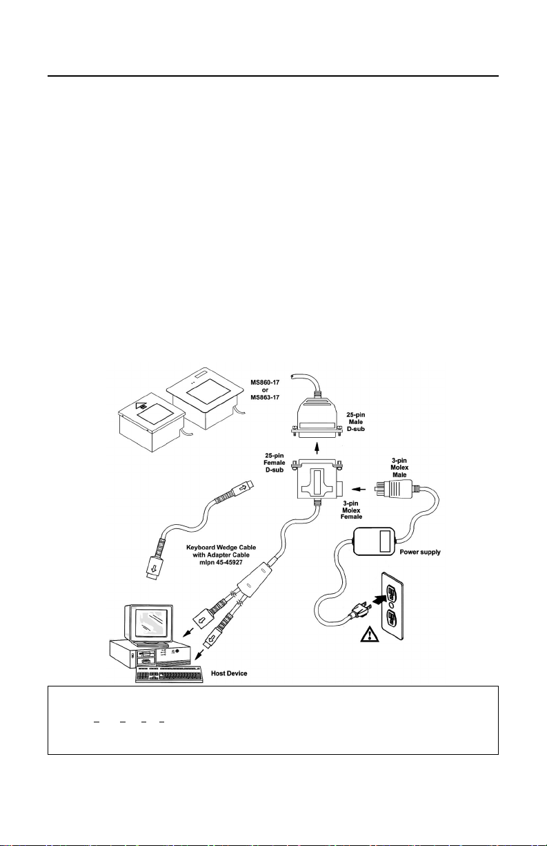
CONNECTION OF A MS860-17 SCANNER TO A PC
1. If the PC is on, exit your application and turn the PC off.
2. Disconnect the keyboard from the PC. Plug the Keyboard Wedge cable to
the PC and the keyboard. Use the adapter cable if necessary.
3. Connect the 25-pin D-type connector on the scanner’s head cable to the
Keyboard Wedge cable.
4. Check the AC input requirements of the transformer to make sure the
voltage matches the AC outlet. A socket outlet should installed near the
equipment and be easily accessible.
5. Plug the transformer into the side of the female D-type connector located on
the communication cable. Plug the transformer into the AC outlet to supply
power to the scanner.
6. Turn the PC on.
7. When the scanner first receives power, the LEDs will flash and the scanner
will beep once. After the scanner performs this start up sequence, the green
LED will remain on for a specified time indicating the laser is on.
Figure 1
Caution:
To maintain compliance with applicable standards, all circuits connected to the scanner must meet the requirements
for SELV (Safety Extra Low Voltage) according to EN 60950.
To maintain compliance with standard CSA C22.2 No. 950/UL 1950 and norm EN 60950, the power source should
meet applicable performance requirements for a limited power source.
10
Page 15

OPTIONAL IN-COUNTER MOUNTING OPTIONS FOR THE MS860
Metrologic has designed three plates to accommodate in-counter installation of
the MS860. Included automatically with the purchase of the MS860 is Metrologic
part #45-45471, Installation Plate. The universal and replacement plates are
available for an additional charge. Contact the distributor, dealer or Metrologic
customer service representative to order one of these plates.
Metrologic Part Number mlpn 45-45471, Installation Plate:
This plate is designed for use in counters with no previous cutouts. No routing is
necessary for a flush fit as the stainless steel top is only .60mm (.024") thick. The
cut out measurements are 180.34 mm (7.1") L x 175.26 mm (6.9”) W. The final
cut out must not be greater than 1.5mm (1/16") or less than the exact
measurement.
Metrologic Part Number mlpn 45-45474, Universal Plate:
This plate is designed to fit into an existing cut out up to 292.1 mm
(11.5") L x 508 mm (20") W.
Metrologic Part Number mlpn 45-45470, Replacement Plate:
This plate is designed to fit into a cut out that previously contained an MS260 or
MS362 scanner. This plate fits into the existing 293.62 mm (11.56") L x
245.36 mm (9.66") W.
11
Page 16
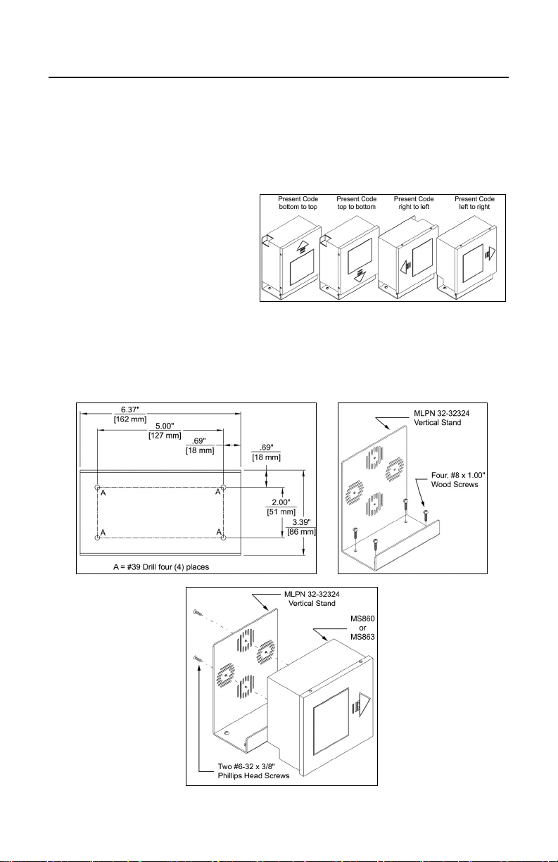
VERTICAL STAND KIT
Vertical Stand Kit, MLPN 45-45472 includes:
a. Vertical Stand [ MLPN 45-45472 ] Qty. 1
b. #6-32 x 3/8” Phillips Head Screw [
c. #8 x 1.00” Round Head Wood Screw [
Installation
Orientation Note:
The arrow on the top of the scanner
indicates the direction that items
must be presented to the scanner.
1. Drill four #39 pilot holes into the counter top (See Figure 2).
2. Screw the stand to the counter top with the four #8 wood screws provided.
3. Secure the unit to the stand using the four #6-32 x 3/8” screws provided (See
Figure 4).
MLPN 18-18317 ] Qty. 2
MLPN 18-18057 ] Qty. 3
12
Figure 3Figure 2
Figure 4
Page 17

SCANNER PARTS
n Touch Plate
When a specified time has
elapsed without any
scanning, the unit will enter
a “standby” mode. Touching
the touch plate arrow on the
top cover will reactivate the
scanner.
o Red LED
When the red LED flashes
ON, the scanner has read
a bar code successfully.
When the red light turns
OFF, communication to
the host is complete.
p Green LED
When the green LED is
ON, this indicates the unit is
receiving power and the
laser is ON.
q Output Window
This aperture emits laser
light.
r Head Cable
This cable can be
connected directly to the
host device or to a
communication cable.
s Stainless Steel Top Plate
(On the MS860 only.)
t Dark Grey ABS Top Plate
(On the MS863 only.)
Figure 5: MS860 & MS863 Scanner Parts
13
Page 18

The MS860 TOUCH PLATE
The MS860 will enter “standby” when it remains dormant for a time. When the
scanner’s computer is on “standby," touching the touch plate will “wake up” the
scanner and activate the laser. When the green LED comes on, the scanner is
powering up for full operation. After approximately three seconds, the scanner
will be ready to operate.
The default touch plate timeout is ten minutes. However, this can be changed
through ScanSet or by scanning a bar code in Section C of the ScanSelect
Programming Guide. The available times are two minutes, thirty minutes or no
timeout.
Plaque de palpeur
Le scanner passe en mode 'Stand-by' quand il n'est pas utilisé pendant une
certaine période. Si le calculateur du scanner se trouve en mode 'Stand-by', le
contacte de la plaque de palpeur "réveille" le scanner et active le laser.
L'allumage de la diode verte indique que le scanner se met en service en attente
d'utilisation. Au bout d'environ 3 secondes, le scanner est prêt à servir.
La temporisation standard de plaque de palpeur est de 10 minutes. Ceci peut
toutefois être modifié avec ScanSet ou par lecture d'un code barres au chapitre C
du manuel de programmation ScanSelect. Les durées disponibles sont deux
minutes, trente minutes ou même aucune temporisation.
Sensorplatte
Der Scanner tritt in den 'Stand-by'-Modus ein, wenn er für einen bestimmten
Zeitraum untätig geblieben ist. Befindet sich der Rechner des Scanners im
'Stand-by'-Modus, "weckt" die Berührung der Sensorplatte den Scanner und
aktiviert den Laser. Das Aufleuchten der grünen Leuchtdiode zeigt an, daß der
Scanner sich für volle Betriebsbereitschaft einschaltet. Nach etwa drei Sekunden
ist der Scanner betriebsbereit.
Der Standard-Sensorfeld-Timeout liegt bei zehn Minuten. Dies kann jedoch
geändert werden durch ScanSet oder Einlesen eines Barcodes in Abschnitt C
des ScanSelect Programmierhandbuchs. Die verfügbaren Zeiträume sind zwei
Minuten, dreißig Minuten oder gar kein Timeout.
Piastra sensore
Se lo scanner è rimasto disattivato per un determinato periodo esso passa in
modalità 'stand-by'. Quando il calcolatore dello scanner si trova in modalità
'stand-by', occorre toccare la piastra sensore per "svegliare" lo scanner ed
attivare il laser. L’accensione del diodo luminoso verde indica che lo scanner si
accende per diventare completamente pronto. Dopo circa tre secondi lo scanner
ha raggiunto la condizione "pronto".
Il timeout standard della zona sensore è regolato su dieci minuti. Questo valore
può, però, essere modificato con lo ScanSet oppure con la lettura di un codice a
barre, come descritto nella sezione C del Manuale di programmazione
ScanSelect. Gli intervalli possibili sono due minuti, trenta minuti oppure nessun
timeout.
14
Page 19

VISUAL INDICATORS
There is a red and green LED at the top of the scanner. When the scanner is on,
the flashing or stationary activity of the LEDs indicates the status of the scan and
scanner.
Steady Green
When the laser is on, the green LED is also on. This occurs when the touch plate
has been touched. The green LED will remain on until the touch plate timeout
elapses or until the scanner turns off.
Steady Green; Red Flash
When the scanner successfully reads a bar code, the red LED will flash then
beep once. If this does not happen, then the bar code has not been successfully
read.
Steady Red and Green
After a successful scan, the scanner transmits the data to the host device. When
the host is not ready to accept the information, the scanner’s red LED will remain
on until the data can be transmitted.
Alternating Red and Green
This indicates the scanner is in program mode.
Steady Red
This indicates the scanner is in ScanSet mode.
No Red or Green LED
There are two reasons why the LEDs will not be illuminated. First, if the scanner
is receiving power and the LEDs are not on, then the scanner has remained
dormant for a specified time and the laser has turned off. To reactivate the unit,
touch the touch plate. Secondly, if the scanner is not receiving power from the
host or transformer, then the LEDs will not turn on.
Flashing Red
This indicates the scanner has experienced a laser subsystem failure. Return the
unit for repair at an authorized service center.
15
Page 20

VISUAL INDICATORS
Signaux optiques
Sur la partie supérieure du scanner se trouvent une diode LED rouge et une
diode LED verte. Quand le scanner est sous tension, les diodes rouge et verte
clignotantes ou allumées vous informent sur l'état du scanner.
Ni la diode rouge, ni la diode verte n'est allumée
Il existe deux raisons possibles pour que les diodes ne s'allument pas.
Premièrement: si le scanner reçoit de l'énergie sans que les diodes ne
s'allument, le scanner est resté sans servir pendant une certaine période et le
laser est désactivé. Pour le réactiver, touchez le palpeur infrarouge.
Deuxièmement: quand le scanner ne reçoit de l'énergie ni de l'ordinateur central,
ni du transformateur, les diodes restant éteintes.
Diode verte reste allumée
Quand le laser est en service, la diode verte s'allume également. C'est le cas
quand vous avez touché le palpeur. La diode verte reste allumée tant que la
temporisation de l'infrarouge dure ou jusqu'à ce que le scanner soit désactivé.
Diode verte reste allumée; diode rouge clignotante
Après lecture avec succès d'un code barres par le scanner, la diode rouge se
met à clignoter, suivie d'un bip sonore unique. Si la diode rouge ne clignote pas
ou quand aucun bip sonore n'est émis, cela signifie que le code barres n'a pas pu
être lu avec succès.
Diode rouge et verte reste allumées
Une fois le palpage effectué avec succès, le scanner transmet les données à
l'ordinateur central. Si ce dernier n'est pas prêt à recevoir les données, la diode
rouge du scanner s'allume jusqu'à ce que les données puissent être transmises.
Diode rouge et verte en alternance
Indique que le scanner se trouve en mode de programmation.
Diode rouge reste allumée
Indique que le scanner se trouve en mode ScanSet.
Diode rouge clignotante
Indique une panne de laser pendant le palpage. Veuillez envoyer votre appareil
chez un concessionnaire pour réparation.
16
Page 21

VISUAL INDICATORS
Optische Anzeigen
Auf dem Scanner befinden sich eine rote und eine grüne Leuchtdiodenanzeige.
Bei eingeschaltetem Scanner geben Ihnen die blinkenden oder feststehenden
Leuchtdiodenanzeigen Aufschluß über den Abtast- und Scannerstatus.
Weder rote noch grüne Leuchtdiodenanzeige
Es gibt zwei mögliche Gründe, weshalb die Leuchtdiodenanzeigen nicht
aufleuchten. Erstens: Wenn der Scanner mit Strom versorgt wird und die
Leuchtdiodenanzeigen nicht aufleuchten, so ist der Scanner für einen
bestimmten Zeitraum untätig geblieben und der Laser ist abgeschaltet. Berühren
Sie das Sensorfeld zur Reaktivierung der Einheit. Zweitens: Wenn der Scanner
weder vom Hostrechner noch vom Transformator Energie erhält, leuchten die
Leuchtdiodenanzeigen ebenfalls nicht auf.
Feststehende grüne Anzeige
Wenn der Laser eingeschaltet ist, leuchtet die grüne Leuchtdiodenanzeige
ebenfalls auf. Dies ist der Fall, wenn das Sensorfeld berührt wurde. Die grüne
Leuchtdiodenanzeige leuchtet solange auf, bis das Sensorfeld-Timeout
abgelaufen ist oder bis der Scanner abgeschaltet wird.
Feststehende grüne Leuchtanzeige; rote Blinkanzeige
Nach erfolgreichem Lesen eines Barcodes durch den Scanner blinkt die rote
Leuchtdiode auf, gefolgt von einem einmaligen Piep-Signal. Blinkt die rote
Leuchtdiodenanzeige nicht auf oder sendet der Scanner kein einmaliges PiepSignal aus, so konnte der Barcode nicht erfolgreich gelesen werden.
Feststehende rote und grüne Leuchtanzeige
Nach erfolgreichem Abtasten überträgt der Scanner die Daten an das Hostgerät.
Falls das Hostgerät zur Datenannahme nicht bereit ist, leuchtet die rote
Leuchtdiodenanzeige solange auf, bis die Daten übertragen werden können.
Alternierende rote und grüne Leuchtanzeige
Zeigt an, daß sich der Scanner im Programmiermodus befindet.
Feststehende rote Leuchtanzeige
Zeigt an, daß sich der Scanner im ScanSet-Modus befindet.
Aufblinkende rote Leuchtanzeige
Zeigt an, daß beim Scanner ein Laserausfall vorliegt. Bringen Sie das Gerät zur
Reparatur in ein Vertragsservicecenter.
17
Page 22

VISUAL INDICATORS
Segnali ottici
Sullo scanner si trovano due diodi luminosi: uno rosso e uno verde. Quando lo
scanner è inserito, i diodi luminosi, che possono o essere accesi in continuazione
o lampeggiare, Vi informano sullo stato della scansione e dell’apparecchio.
Né il diodo luminoso rosso né quello verde sono accesi
Vi sono due possibili cause se i diodi luminosi non sono accesi. Prima causa: se
lo scanner viene alimentato e i diodi luminosi non sono accesi, lo scanner è
rimasto disattivato per un determinato periodo e il laser è spento. Per riattivare
l’unità dovreste toccare la zona sensore. Seconda causa: se lo scanner non
viene alimentato né dal calcolatore host né dal trasformatore, i due diodi luminosi
non sono accesi.
Il diodo luminoso verde è acceso
Quando il laser è inserito, è acceso anche il diodo luminoso verde. Questo si ha
quando la zona sensore è stata toccata. Il diodo luminoso verde è acceso fino al
raggiungimento del timeout della zona sensore oppure fino allo spegnimento
dello scanner.
Il diodo luminoso verde è acceso; quello rosso lampeggia
Dopo la lettura riuscita di un codice a barre da parte dello scanner il diodo
luminoso rosso lampeggia e quindi viene emesso un unico segnale beep. Se il
diodo luminoso rosso non lampeggia oppure lo scanner non emette un segnale
beep unico, ciò significa che la lettura del codice a barre non è riuscita.
Sono accesi sia il diodo luminoso rosso che quello verde
Dopo la scansione riuscita lo scanner trasmette i dati all’host. Se l’host non è
pronto per accettare i dati, il diodo luminoso rosso dello scanner è acceso fino a
che i dati possono essere trasmessi.
Il diodo luminoso rosso e quello verde sono accesi in alternanza
Ciò indica che lo scanner si trova nella modalità di programmazione.
Il diodo luminoso rosso è acceso
Ciò indica che lo scanner si trova nella modalità ScanSet.
Il diodo luminoso rosso lampeggia
Ciò indica che lo scanner ha un guasto a livello del laser. Fate riparare
l’apparecchio da un centro di assistenza autorizzato.
18
Page 23

VOLUME SETTINGS
There are four volume settings available: low, medium, high and no volume. The
operator can temporarily change the volume of the scanner by scanning the bar
codes on the volume control card. To change the volume of the scanner
permanently, enter program mode and scan the appropriate volume setting bar
code in Section C of the ScanSelect
0
®
Programming Guide or use ScanSet®.
Scan for Louder Volume
12345 88888
5
19
Page 24

VOLUME SETTINGS (CONT.)
Scan for Softer Volume
12345 88887
0
8
20
Page 25
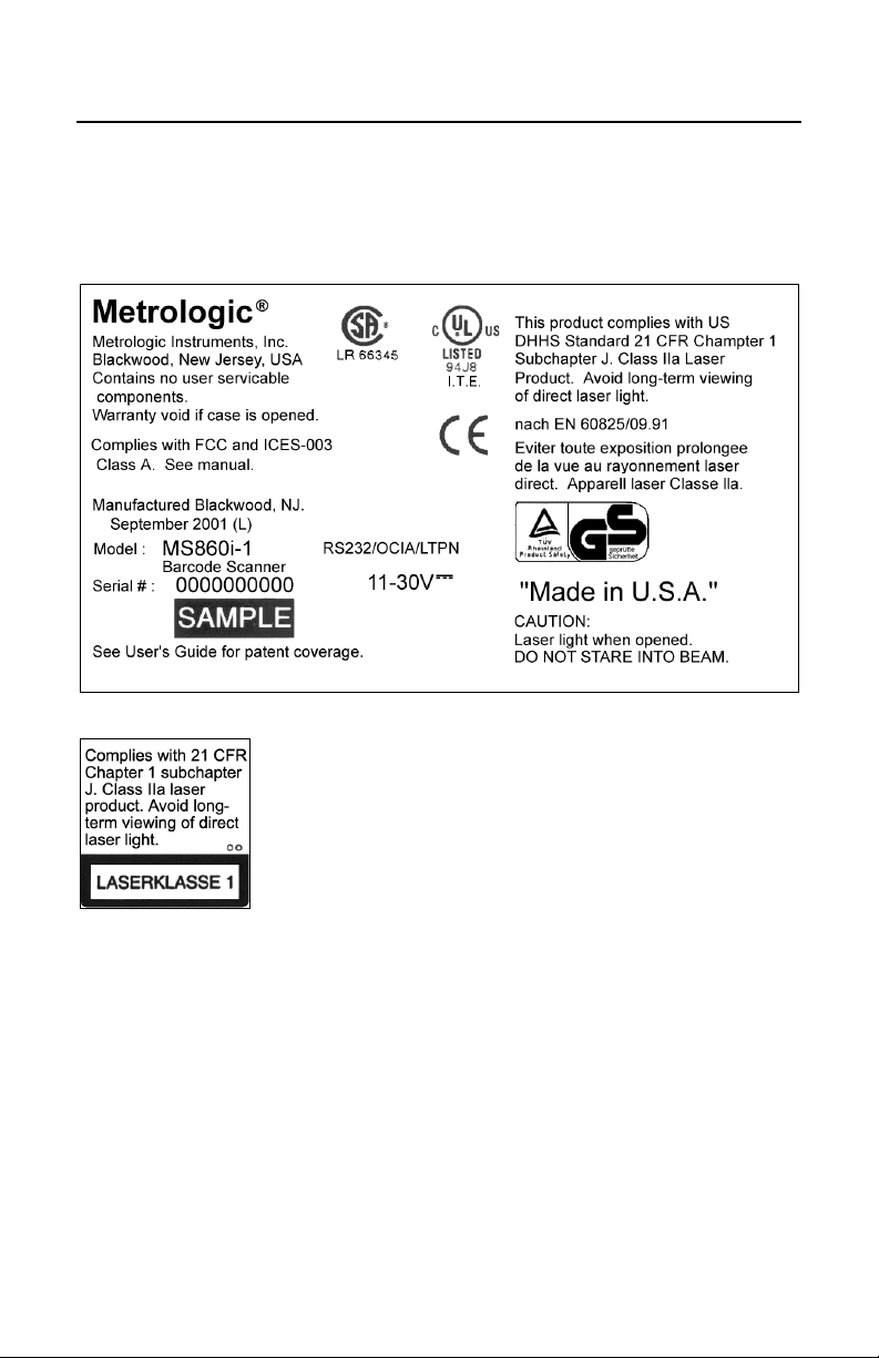
LABELS
There is one label located inside the window of the scanner noting that the device
is a CDRH Class IIa laser product and IEC 825 LASERKLASSE 1.. Another
label, located on the back of the unit, shows the model number, date of
manufacture, and serial number. The following are samples of these labels:
Figure 5: Labels
21
Page 26
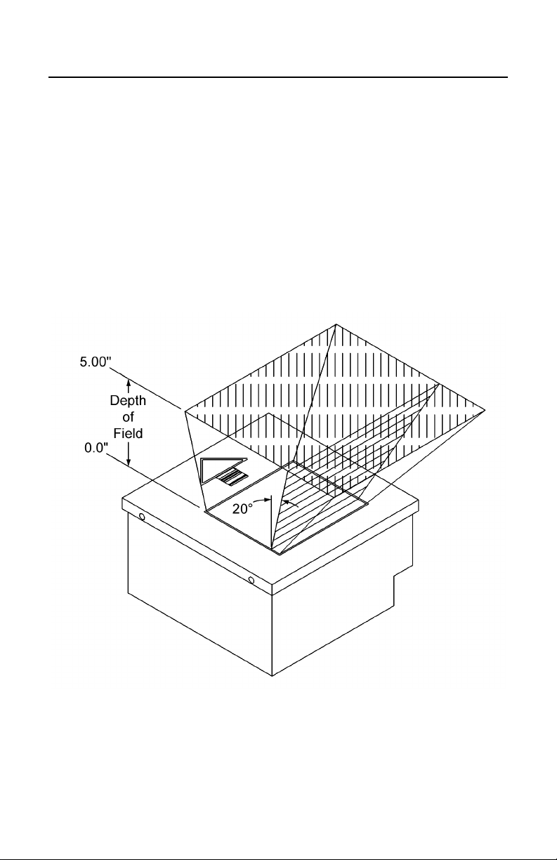
DEPTH OF FIELD
Through the glass at the front of the scanner, safe, low powered laser beams are
projected in a complex pattern that resembles a spider web. Each of the five
scan fields that generate the scan pattern extend to a range of 127mm (5.0").
This range begins from the face of the scanner window and extends from the unit
for a distance of 127mm (5.0") measured along the scanning beam at the center
of each scan segment. This 0.0mm - 127mm (0" - 5") range is the depth of field
for the MS860i scanner (see figure 6).
The scan pattern is projected at an angle away from the touch plate
(approximately 20 degrees, overall). As the scan fields move outward, they
expand. Like an image expands from a film projector as it moves toward the
screen at a movie theater, the scan pattern projects out to a well-defined region.
Any label that is facing toward the scanner can be read at any point within the
scanning field.
22
Figure 6: Depth of Field
Page 27

DEPTH OF FIELD AND SYMBOL SPECIFICATION
CODE TYPE
UPC/EAN 10.4 80% 0" - 5"
UPC/EAN 13.0 100% 0" - 6.5"
Code 39 7.5 High 0" - 3"
Code 39 12.0 Medium 0" - 6"
Code 39 21.0 Low 0" - 8"
I 2 of 5 7.5 High 0" - 3"
I 2 of 5 12.0 Medium 0" - 6"
I 2 of 5 21.0 Low 0" - 8"
Codabar 6.5 High 0" - 3"
Codabar 9.8 Medium 0" - 5"
Codabar 13.0 Low 0" - 6.5"
MINIMUM SMALL ELEMENT
MIL. (1/1000)
CODE DENSITY
DEPTH OF
FIELD
Code 93 10.4 80% 0" - 5"
Code 93 13.0 100% 0" - 6.5"
Code 128 10.4 80% 0" - 5"
Code 128 13.0 100% 0" - 6.5"
23
Page 28

DEPTH OF FIELD AND SYMBOL SPECIFICATION
24
mm
mils
MINIMUM BAR CODE ELEMENT WIDTH
ABCDE
.19 .25 .31 .33 .53
7.510121321
Figure 7: Depth of Field and Symbol Specification
Page 29

MAINTENANCE
Smudges and dirt can interfere with the proper scanning of a bar code.
Therefore, the output window will need occasional cleaning.
1. Spray glass cleaner onto lint free, non-abrasive cleaning cloth.
2. Gently wipe the scanner window.
25
Page 30

SPECIFICATIONS
Application: In-Counter Laser Bar Code Scanner
Light Source: VLD 650 ± 10 nm
Laser Power 0.525 mW (peak)
MS860 AND MS863 SPECIFICATIONS
Laser Class
UL/CSA/TUV:
MECHANICAL
Dimensions: 175 mm (6.9")L x 173 mm (6.8")W x 97 mm(3.8")H
Orientation: May be used in any orientation
ELECTRICAL
CDRH: CLASS IIa; EN60825-1:1994/A11:1996
Class 1
UL Listed, UL 1950; CSA certified, C22.2 No. 950;
TUV certified, GS Mark, and EN 60950
EMC: FCC, ICES-003 & EN 55022 Class A
Weight: 2.45 kg (5.4 lbs.)
MS860: Brushed stainless steel
Top Cover:
MS863: ABS Plastic
Cable:
Power: 8.4 W, host system or desk transformer
1.8 m (6'); contact a Metrologic customer service
representative for additional cable options
Input Voltage: 11-30VDC ± 0.50VDC
Operating Current: 350 mA @ 20VDC
Standby Current: 175 mA @ 20VDC
DC Transformers: Class 2; 20VDC @ 750 mA
Specifications subject to change without notice.
26
Page 31

SPECIFICATIONS (CONT.)
MS860 AND MS863 SPECIFICATIONS
OPERATIONAL
Depth of Field: 0 mm - 203 mm (0" - 8"), programmable
Minimum Bar Width: 0.191 mm (7.5 mil)
Scan Speed: 2000 scan lines per second
Scan Pattern: 5 fields of 4 parallel lines (omnidirectional)
Exit Angle: 70°
Indicators (LED):
Beeper Operation: 3 tones or no beep; 3 volume settings
Maintenance: Clean window periodically
Decode Capability:
System Interfaces:
Print Contrast: 35% minimum reflectance difference
Roll, Pitch, Yaw: 360°, 60°, 60°
Green = laser on, ready to scan
Red = good read
Autodiscriminates all standard bar codes; for other
symbologies call Metrologic
RS232, OCIA, OCR A/B Parallel, IBM
Light Pen Emulation, Point to Point RS422,
Keyboard Wedge
ENVIRONMENTAL
Storage Temperature: -40°C - 60°C (-40°F - 140°F)
Operating Temperature: 0°C - 40°C (32°F - 104°F)
Humidity: 5% - 95% relative humidity, non-condensing
Light Levels: Up to 4842 Lux (450 footcandles)
Ventilation: None required
Shock: 100g for 1ms
468X/469X,
ESD: 8 kV IEC 801-2
Contaminants: Sealed to resist airborne particulate contaminants
Specifications subject to change without notice.
27
Page 32

DEFAULT SETTINGS
Many function of the scanner can be “ programmed” - that is, enabled or
disabled. The scanner is shipped from the factory programmed to a set of default
conditions. The default parameter of the scanner has an asterisk (*) in the charts
on the following pages. If an asterisk is not in the default column then the default
setting is OFF or DISABLED. Every communication does not support every
parameter. If the communication supports a parameter listed in the charts on the
following pages, a check mark will appear.
PARAMET ER DEFAULT OCIA
UPC/EAN
Code 128
Code 93
Codabar
Interleaved 2
of 5 (ITF)
MOD 10 Check
on ITF
Code 11
Code 39
Full ASCII
Code 39
MOD 43 Check
on Code 39
MSI Plessey
MSI Plessey
10/10 Check
Digit
MSI Plessey
MOD 10 Check
Digit
UK Plessey
*
*
*
*
*
*
*
IBM
46XX
KEYBOARD
WEDGE
RS-232* PAR ALLEL
LIGHT
PEN
99 9 9 9 9
99 9 9 9
99 9 9 9
99 9 9 9
99 9 9 9
99 9 9 9
99 9 9 9
99 9 9 9
99 9 9 9
99 9 9 9
99 9 9 9
99 9 9 9
99 9 9 9
99 9 9
Airline 2 of 5
Telepen
MECCA
28
99 9 9
99 9 9
99 9 9 9 9
Page 33

DEFAULT SETTINGS (CONT.)
PARAMET ER DEFAULT OCIA
IBM
46XX
KEYBOARD
WEDGE
RS-232* PARALLEL
LIGHT
PEN
Paraf Support
Matrix 2 of 5
EAN-8
EAN-13
UPC-E
UPC-A
ITF Symbol
Lengths
Minimum
Symbol Length
Symbol Length
Lock
SWEDA
Fujitsu
OMRON
IBM Parallel
Bars High as
Code 39
Spaces High as
Code 39
Bars High as
Scanned
Spaces High as
Scanned
DTS/SIEMENS
DTS/NIXDORF
NCR F
NCR S
Poll Light Pen
Source
Light Pen Extra
Transition
Before Bar
Code
*
*
*
*
Var.
04
None
*
*
*
99 9 9 9
99 9 9
99 9 9 9 9
99 9 9 9 9
99 9 9 9 9
99 9 9 9 9
99 9 9 9 9
99 9 9 9 9
99 9 9 9 9
9
9
9
9
9
9
9
9
9
9
9
9
9
9
29
Page 34

DEFAULT SETTINGS (CONT.)
PARAMET ER DEFAULT OCIA
Multi-drop
Address
IBM
46XX
KEYBOARD
WEDGE
RS-232* PARALLE L
LIGHT
PEN
Beeper Tone Normal
Fast Beep
Volume Setting Loudest
Beep/Transmit
Sequence
Communication
Timeout
Razzberry Tone
on Timeout
Three Beeps on
Timeout
No Beeps on
Timeout
Touch Plate
Timeout
No Same
Symbol Timeout
Before
None
10 Min.
99 9 9 9 9
99 9 9 9 9
99 9 9 9 9
99 9 9 9 9
99 9 9 9 9
99 9 9 9 9
99 9 9 9 9
99 9 9 9 9
99 9 9 9 9
99 9 9 9 9
Infinite Same
Symbol Timeout
Same Symbol
Rescan Timeout:
100 msec
Same Symbol
Rescan Timeout:
200 msecs
30
99 9 9 9 9
99 9 9 9 9
99 9 9 9 9
Page 35

DEFAULT SETTINGS (CONT.)
PARAMET ER DEFAULT OCIA
Same Symbol
Rescan Timeout:
500 msecs
Same Symbol
Rescan Timeout:
1250 msecs
Same Symbol
Rescan Timeout:
2000 msecs
99 9 9 9 9
*
99 9 9 9 9
99 9 9 9 9
IBM
46XX
KEYBOARD
WEDGE
RS-232* PARALLEL
LIGHT
PEN
Scanability Off
Scan Count
Mode
Normal Depth of
Field
Intercharacter
Delay
Scan Buffer 1
Transmit UPC-A
Check Digit
Transmit UPC-E
Check Digit
Expand UPC-E
Convert UPC-A
to EAN-13
Transmit Lead
Zero on UPC-E
Convert EAN-8
to EAN-13
Transmit EAN-
13 Check Digit
Off
1 msec
9
9
99 9 9 9 9
*
9999
99 9 9 9 9
99 9 9 9
*
99 9 9 9
99 9 9 9
99 9 9 9
99 9 9 9
99 9 9 9
99 9 9 9
*
31
Page 36

DEFAULT SETTINGS (CONT.)
PARAMET ER DEFAULT OCIA
IBM
46XX
KEYBOARD
WEDGE
RS-232* PARALLEL
LIGHT
PEN
Transmit EAN-8
Check Digit
Transmit UPC-A
Number System
Transmit
Codabar
Start/Stop
Characters
Transmit Mod 43
Check Digit on
Code 39
Transmit Code
39 Stop/Start
Characters
Transmit Mod
10/ITF
Transmit Code
11 Check Digit
Transmit MSI
Plessey Check
Digits
Transmit UK
Plessey Check
Digits
Parity Space
*
*
99 9 9 9
99 9 9 9
99 9 9 9
99 9 9
99 9 9
99 9 9
99 9 9 9
99 9 9
99 9 9
9
Baud Rate 9600
8 Data Bits
7 Data Bits
Transmit Sanyo
ID Characters
Shell
Schulmberger
Formatting
SNI Beetle Mode
32
9
9
*
9
99
99
99
Page 37

DEFAULT SETTINGS (CONT.)
PARAMET ER DEFAULT OCIA
IBM
46XX
KEYBOARD
WEDGE
RS-232* PARALLEL
LIGHT
PEN
CLSI Editing
French PC Term
Transmit AIM ID
Characters
Nixdorf ID
UPC Prefix
UPC Suffix
STX Prefix
ETX Suffix
Carriage Return
Line Feed
Tab Prefix
Tab Suffix
"DE" Disable
Command
"FL" Laser
Enable
Command
DTR
Handshaking
Support
RTS/CTS
Handshaking
Character
RTS/CTS
Message
RTS/CTS
XON/XOFF
Handshaking
ACK/NAK
5 Retries on
ACK/NAK
Time-out
Keyboard
Country Type
*
*
*
USA
99 9 9
9
99
99
99
99
99
99
99
99
99
99
9
9
9
9
9
9
9
9
9
9
33
Page 38

DEFAULT SETTINGS (CONT.)
PARAMET ER DEFAULT OCIA
Keyboard Type AT
Caps Lock
Alt Mode
IBM
46XX
KEYBOARD
WEDGE
9
9
9
RS-232* PARALLEL
LIGHT
PEN
Inter Scan Code
Delay
Transmit F0H
Break Code (AT
and PS/2
keyboards)
Special Software is required for the following:
Two Digit
Supplements
Five Digit
Supplements
Bookland
977 (2 digit)
Supplemental
Requirement
Supplements
are not
Required
Two Digit
Redundancy
Five Digit
Redundancy
200 msec to
Find
Supplement
100 msec to
Find
Supplement
Code 128
Coupon
Extended Code
Code 128 ]C1
Extended Code
Format
800
µsec
*
*
*
*
99 9 9 9
99 9 9 9
99 9 9 9
99 9 9 9
99 9 9 9
99 9 9 9
99 9 9 9
99 9 9 9
99 9 9 9
99 9 9
99 9 9
9
9
34
Page 39

SCANNER PINOUT CONNECTIONS
Version “1” Pin Assignments for RS-232, OCIA and
Light Pen Emulation
The version “1” scanner head cable is terminated with a male 25-pin D-type
connector. Connecting the scanner to the host device may require a
communication cable. The communication cable may include a connection for a
transformer or it may be designed to draw power directly from the host device.
This can be ordered when the scanner is purchased.
The version “1” scanner is designed to be used for RS-232, OCIA or Light Pen
Emulation communication.
The following is a list of the pin assignments. The pin numbers are impressed on
the head cable’s connector.
PIN FUNCTION
1 AC Shield Ground
2 RS-232 Receive Input
3 RS-232 Transmit Output
4 CTS Input
5 RTS Output
6 Reserved
7 Signal Ground
8 - 12 Reserved
13 Earth Ground
14 Power Ground 1
15 Light Pen Source
16 Light Pen Data
17 OCIA Clock In Return
18 OCIA Clock In
19 Power (11 - 30 volts) DC
20 DTR Input
21 OCIA Clock Out
22 OCIA Clock Out Return
23 OCIA RDATA
24 OCIA RDATA Return
25 Power Ground 2
35
Page 40

SCANNER PINOUT CONNECTIONS
Version “2” Pin Assignments for Parallel Communication
The version “2” scanner head cable is terminated with a male 25-pin D-type
connector. Connecting the scanner to the host device may require a
communication cable. The communication cable may include a connection for a
transformer or it may be designed to draw power directly from the host device.
This can be ordered when the scanner is purchased.
The version “2” scanner is designed to be used for Parallel communication.
The following is a list of the pin assignments. The pin numbers are impressed on
the head cable’s connector.
PIN FUNCTION
1 AC Shield Ground
2 RS-232 Receive Input
3 RS-232 Transmit Output
4 CTS Input
5 RTS Output
6 Reserved
7 Signal Ground
8 Reserved
9 Edit Check
10 EOT
11 Data Ready
12 Adaptor Ready
13 Earth Ground
14 Power Ground 1
15 Light Pen Source
16 Light Pen Data
17 Data 1
18 Data 2
19 Power (11 - 30 volts) DC
20 DTR Input
21 Data 3
22 Data 4
23 Data 5
24 Data 6
25 Power Ground 2
36
Page 41

SCANNER PINOUT CONNECTIONS
Version “11” Pin Assignments for RS-485
The version “11” scanner head cable is terminated with a male 25-pin D-type
connector. Connecting the scanner to the host device may require a
communication cable. The communication cable may include a connection for a
transformer or it may be designed to draw power directly from the host device.
This can be ordered when the scanner is purchased.
The version “11” scanner is designed to be used primarily with IBM 46XX series
of electronic cash registers. It can also be configured to communicate using the
full RS-232 and OCIA protocol.
The following is a list of the pin assignments. The pin numbers are impressed on
the head cable’s connector.
PIN FUNCTION
1 AC Shield Ground
2 RS-232 Receive Input
3 RS-232 Transmit Output
4 CTS Input
5 RTS Output
6 Reserved
7 Signal Ground
8 - 12 Reserved
13 Earth Ground
14 Power Ground 1
15 468X -B
16 468X +A
17 OCIA Clock In Return
18 OCIA Clock In
19 Power (11 - 30 volts) DC
20 DTR Input
21 OCIA Clock Out
22 OCIA Clock Out Return
23 OCIA RDATA
24 OCIA RDATA Return
25 Power Ground 2
37
Page 42

SCANNER PINOUT CONNECTIONS
Version “17” Pin Assignments for Keyboard Wedge, RS-232 and Light
Pen Emulation
The version “17” scanner head cable is terminated with a male 25-pin D-type
connector. Connecting the scanner to a PC, requires a communication cable and
a transformer. Connecting the communication cable to a PC, may require an
adapter cable.
The version “17” scanner is designed to be used as a keyboard wedge. With the
appropriate communication cable, the scanner will also provide an RS-232 or
light pen emulation interface. When configuring the scanner for an interface it is
necessary to set the correct parameters for that interface. For further information
on configuring interfaces, refer to the ScanSelect Scanner Programming Guide or
ScanSet Scanner Configuration Guide.
The following is a list of the pin assignments. The pin numbers are impressed on
the head cable’s connector.
PIN FUNCTION
1 AC Shield Ground
2 RS-232 Receive Input
3 RS-232 Transmit Output
4 CTS Input
5 RTS Output
6 Reserved
7 Signal Ground
8 - 10 Reserved
11 PC +5 Volts DC
12 Ground
13 Earth Ground
14 Power Ground 1
15 Light Pen Source
16 Light Pen Data
17 PC Data
18 PC Clock
19 Power (11 - 30 volts) DC
20 DTR Input
21 Keyboard Clock
22 Keyboard Data
23 - 24 Reserved
25 Power Ground 2
38
Page 43

Limited Warranty
The MS860 and MS863 scanners are manufactured by Metrologic at its Blackwood, New
Jersey, U.S.A. facility. The MS860 and MS863 scanners have a two (2) year limited
warranty from the date of manufacture. Metrologic warrants and represents that all MS860
and MS863 scanners are free of all defects in material, workmanship and design, and have
been produced and labeled in compliance with all applicable U.S. Federal, state and local
laws, regulations and ordinances pertaining to their production and labeling.
This warranty is limited to repair, replacement of Product or refund of Product price at the
sole discretion of Metrologic. Faulty equipment must be returned to the Metrologic facility in
Blackwood, New Jersey, U.S.A. or Puchheim, Germany. To do this, contact Metrologic’s
Customer Service/Repair Department to obtain a Returned Material Authorization (RMA)
number.
In the event that it is determined the equipment failure is covered under this warranty,
Metrologic shall, at its sole option, repair the Product or replace the Product with a
functionally equivalent unit and return such repaired or replaced Product without charge
for service or return freight, whether distributor, dealer/reseller, or retail consumer, or
refund an amount equal to the original purchase price.
This limited warranty does not extend to any Product which, in the sole judgement of
Metrologic, has been subjected to abuse, misuse, neglect, improper installation, or
accident, nor any damage due to use or misuse produced from integration of the Product
into any mechanical, electrical or computer system. The warranty is void if the case of
Product is opened by anyone other than Metrologic’s repair department or authorized
repair centers.
THIS LIMITED WARRANTY, EXCEPT AS TO TITLE, IS IN LIEU OF ALL OTHER
WARRANTIES OR GUARANTEES, EITHER EXPRESS OR IMPLIED, AND
SPECIFICALLY EXCLUDES, WITHOUT LIMITATION, WARRANTIES OF
MERCHANTABILITY AND FITNESS FOR A PARTICULAR PURPOSE UNDER THE
UNIFORM COMMERCIAL CODE, OR ARISING OUT OF CUSTOM OR CONDUCT.
THE RIGHTS AND REMEDIES PROVIDED HEREIN ARE EXCLUSIVE AND IN LIEU
OF ANY OTHER RIGHTS OR REMEDIES. IN NO EVENT SHALL METROLOGIC BE
LIABLE FOR ANY INDIRECT OR CONSEQUENTIAL DAMAGES, INCIDENTAL
DAMAGES, DAMAGES TO PERSON OR PROPERTY, OR EFFECT ON BUSINESS OR
PROPERTY, OR OTHER DAMAGES OR EXPENSES DUE DIRECTLY OR
INDIRECTLY TO THE PRODUCT, EXCEPT AS STATED IN THIS WARRANTY. IN NO
EVENT SHALL ANY LIABILITY OF METROLOGIC EXCEED THE ACTUAL AMOUNT
PAID TO METROLOGIC FOR THE PRODUCT. METROLOGIC RESERVES THE
RIGHT TO MAKE ANY CHANGES TO THE PRODUCT DESCRIBED HEREIN.
Corporate Headquarters
Metrologic Instruments, Inc. Customer Service: 1-800-ID-METRO
90 Coles Road Tel: 856-228-8100
Blackwood, NJ 08012-4683 Fax: 856-228-6673
Germany
Metrologic Instruments GmbH Tel: 49-89-89019-0
Dornierstrasse 2 Fax: 49-89-89019-200
82178 Puchheim b. Email: info@europe.metrologic.com
Munich, Germany
Email: info@metrologic.com
Website: www.metrologic.com
39
Page 44

NOTICES
Notice
This equipment has been tested and found to comply with limits for a Class A digital device, pursuant to
part 15 of the FCC Rules. These limits are designed to provide reasonable protection against harmful
interference when the equipment is operated in a commercial environment. This equipment generates,
uses and can radiate radio frequency energy and, if not installed and used in accordance with the
instruction manual, may cause harmful interference to radio communications. Operation of this
equipment in a residential area is likely to cause harmful interference, in which case the user will be
required to correct the interference at his own expense. Any unauthorized changes or modifications to
this equipment could void the users authority to operate this device.
This device complies with part 15 of the FCC Rules. Operation is subject to the following two conditions:
(1) This device may not cause harmful interference, and (2) this device must accept any interference
received, including interference that may cause undesired operation.
Notice
This Class A digital apparatus complies with Canadian ICES-003.
Remarque
Cet appareil numérique de la classe A, conformé a la norme NMB-003 du Canada.
Caution
Use of controls or adjustments or performance of procedures other than those specified herein may result
in hazardous laser light exposure. Under no circumstances should the customer attempt to service the
laser scanner. Never attempt to look at the laser beam, even if the scanner appears to be nonfunctional.
Never open the scanner in an attempt to look into the device. Doing so could result in hazardous laser
light exposure. The use of optical instruments with the laser equipment will increase eye hazard.
Atención
La modificación de los procedimientos, o la utilización de controles o ajustes distintos de los
especificados aquí, pueden provocar una luz de láser peligrosa. Bajo ninguna circunstancia el usuario
deberá realizar el mantenimiento del láser del escáner. Ni intentar mirar al haz del láser incluso cuando
este no esté operativo. Tampoco deberá abrir el escáner para examinar el aparato. El hacerlo puede
conllevar una exposición peligrosa a la luz de láser. El uso de instrumentos ópticos con el equipo láser
puede incrementar el riesgo para la vista.
Attention
L'emploi de commandes, réglages ou procédés autres que ceux décrits ici peut entraîner de graves
irradiations. Le client ne doit en aucun cas essayer d'entretenir lui-même le scanner ou le laser. Ne
regardez jamais directement le rayon laser, même si vous croyez que le scanner est inactif. N'ouvrez
jamais le scanner pour regarder dans l'appareil. Ce faisant, vous vous exposez à une rayonnement laser
qú êst hazardous. L'emploi d'appareils optiques avec cet équipement laser augmente le risque
d'endommagement de la vision.
Achtung
Die Verwendung anderer als der hier beschriebenen Steuerungen, Einstellungen oder Verfahren kann
eine gefährliche Laserstrahlung hervorrufen. Der Kunde sollte unter keinen Umständen versuchen, den
Laser-Scanner selbst zu warten. Sehen Sie niemals in den Laserstrahl, selbst wenn Sie glauben, daß
der Scanner nicht aktiv ist. Öffnen Sie niemals den Scanner, um in das Gerät hineinzusehen. Wenn Sie
dies tun, können Sie sich einer gefährlichen Laserstrahlung aussetzen. Der Einsatz optischer Geräte mit
dieser Laserausrüstung erhöht das Risiko einer Sehschädigung.
40
Page 45
NOTICES (CONT.)
Attenzione
L’utilizzo di sistemi di controllo, di regolazioni o di procedimenti diversi da quelli descritti nel presente
Manuale può provocare delle esposizioni a raggi laser rischiose. Il cliente non deve assolutamente
tentare di riparare egli stesso lo scanner laser. Non guardate mai il raggio laser, anche se credete che
lo scanner non sia attivo. Non aprite mai lo scanner per guardare dentro l’apparecchio. Facendolo potete
esporVi ad una esposizione laser rischiosa. L’uso di apparecchi ottici, equipaggiati con raggi laser,
aumenta il rischio di danni alla vista.
European Standard
Warning
This is a class A product. In a domestic environment this product may cause radio interference in
which case the user may be required to take adequate measures.
Funkstöreigenschaften nach EN 55022:1998
Warnung!
Dies ist eine Einrichtung der Klasse A. Diese Einrichtung kann im Wohnbereich Funkstörungen
verursachen; in diesem fall kann vom Betrieber verlangt werden, angemessene Maßnahmen
durchführen.
Standard Europeo
Attenzione
Questo e’ un prodotto di classe A. Se usato in vicinanza di residenze private potrebbe causare
interferenze radio che potrebbero richiedere all’utilizzatore opportune misure.
Attention
Ce produit est de classe “A”. Dans un environnement domestique, ce produit peut être la cause
d’interférences radio. Dans ce cas l’utiliseteur peut être amené à predre les mesures adéquates.
41
Page 46

PATENTS
Patent Information
This METROLOGIC product may be covered by one or more of the following
U.S. Patents:
U.S. Patent No. 4,360,798; 4,369,361; 4,387,297; 4,460,120; 4,496,831;
4,593,186; 4,607,156; 4,673,805; 4,736,095; 4,758,717; 4,816,660;
4,845,350; 4,896,026; 4,923,281; 4,933,538; 4,960,985; 4,992,717;
5,015,833; 5,017,765; 5,059,779; 5,081,342; 5,117,098; 5,124,539;
5,130,520; 5,132,525; 5,140,144; 5,149,950; 5,180,904; 5,200,599;
5,216,232; 5,229,591; 5,247,162; 5,250,790; 5,250,791; 5,250,792;
5,260,553; 5,262,628; 5,280,162; 5,280,164; 5,304,788; 5,321,246;
5,324,924; 5,396,053; 5,396,055; 5,408,081; 5,410,139; 5,436,440;
5,449,891; 5,468,949; 5,479,000; 5,532,469; 5,545,889; 5,557,093;
5,627,359; 5,637,852; 5,777,315; 5,789,731
No license right or sublicense is granted, either expressly or by implication,
estoppel, or otherwise, under any METROLOGIC or third party intellectual
property rights (whether or not such third party rights are licensed to
METROLOGIC), including any third party patent listed above, except for an
implied license only for the normal intended use of the specific equipment,
circuits, and devices represented by or contained in the METROLOGIC
products that are physically transferred to the user, and only to the extent of
METROLOGIC’s license rights and subject to any conditions, covenants and
restrictions therein.
42
Page 47

INDEX
A
Adapter Cable ...............1, 6, 10, 38
Application...................................10
B
Bar codes ..........................1, 19, 27
Base ..............................................8
Beeper........... 3, 4, 7, 10, 15, 18, 27
C
Cable........ 3, 5, 9, 10, 13, 26, 35-38
adapter.......................1, 6, 10, 38
cloning .......................................5
communication 1-4, 7-10, 13, 28,
35-38
Caution.................................... 3, 10
CE ...............................................40
Class ...........................................41
Communications buffer..................7
Communications bus.....................6
Compliance .......................3, 10, 39
Configuration ............................. 6, 8
Customer Service.................... ii, 39
D
Default settings..............................4
E
Electrical...................................... 39
ESD.............................................27
External Power supply................... 6
G
Good read ...................................27
Green LED ............3, 10, 13, 14, 15
I
Indicators ...................................... 1
LED ................... 1, 13, 15, 16, 27
Installation............................. 11, 39
Interfaces ................................ 4, 38
K
keyboard wedge.................. 1, 9, 38
L
Labels ......................................... 21
LASERKLASSE 1 ....................... 21
LEDs ................................. 3, 10, 15
M
Maintenance ......................... 25, 27
MECCA................................... 1, 28
Mechanical.................................. 26
N
Notices.................................. 40, 41
O
OCIA ............................ 1, 27-35, 37
Operation .............................. 27, 40
Operational ................................. 27
Orientation ............................ 12, 26
P
Parts ........................................... 13
Patents........................................ 42
PC........................... 1, 9, 10, 33, 38
Pin Assignments ..........3, 10, 35-38
Property ...................................... 42
H
Host........ 3, 4, 13, 15, 18, 26, 35-37
Humidity ......................................27
R
Red LED ..................................... 13
Repair ......................................... 39
RMA............................................ 39
RS-485................................ 1, 6, 37
43
Page 48

INDEX
S
ScanSelect .. 1, 2, 4, 7, 9, 14, 19, 38
ScanSet............ 1, 4, 7, 9, 14-19, 38
Service ........................................39
Specifications ........................26, 27
Stand.................................2, 12, 14
T
Temperature................................27
U
UL/CSA/TUV ...............................26
V
Ventilation ................................... 27
Voltage.............................. 3, 10, 26
Volume control card .... 2, 19, 20, 30
W
Warranty ..................................... 39
Weight......................................... 26
Window ....................................... 13
44
Page 49

NOTES
Page 50

NOTES
Page 51

Page 52

August 2002
Printed in the USA
00- 02202A
 Loading...