

Page 1
Page 2

Page 3

LOCATIONS
CORPORATE HEADQUARTERS
North America Metrologic Instruments, Inc. Customer Service: 1-800-ID-METRO
EUROPEAN HEADQUARTERS
Germany, Metrologic Instruments GmbH Tel: +49 (0) 89 89019 0
Middle East and Africa Dornierstrasse 2 Fax: +49 (0) 89 89019 200
Spain Metrologic Eria lbérica SL Tel: +34 913 272 400
Italy Metrologic Italia Srl Tel: +39 0 51 6511978
France Metrologic Eria France SA Tel: +33 (0) 1 48.63.78.78
United Kingdom Metrologic Instruments UK Limited Tel: +44 (0) 1256 365900
ASIA
90 Coles Road Tel: 856-228-8100
Blackwood, NJ 08012-4683 Fax: 856-228-6673
82178 Puchheim b. Email: info@europe.metrologic.com
Munich, Germany
Julián Camarillo, 29 D-1 Fax: +34 913 273 829
Edificio Diapasón Email: info@es.metrologic.com
28037 Madrid
Via Emilia 70 Fax: +39 0 51 6521337
40064 Ozzano dell’Emilia (BO) Email: info@it.metrologic.com
69 Rue de la Belle Etoile Fax: +33 (0) 1 48.63.24.94
ZI Paris Nord II, BP 50057 Email: info@fr.metrologic.com
95947 – ROISSY CDG CEDEX
58 Tempus Business Centre Fax: +44 (0) 1256 365955
Kingsclere Road, Basingstoke Email: info@uk.metrologic.com
Hampshire RG21 6XG
Email: info@metrologic.com
Internet: www.metrologic.com
Singapore Metrologic Asia (Pte) Ltd Tel: 65-842-7155
China Metro (Suzhou) Technologies Co., Ltd. Tel: 86-512-62572511
Japan Metrologic Japan Co., Ltd. Tel: 81-3-3839-8511
SOUTH AMERICA
Brazil Metrologic do Brasil Ltda. Tel: 55-11-5182-8226
Outside Brazil Metrologic South America Tel: 55-11-5182-7273
OPYRIGHT
C
© 2002 by Metrologic Instruments, Inc. All rights reserved. No part of this work may be reproduced, transmitted, or stored
in any form or by any means without prior written consent, except by reviewer, who may quote brief passages in a review,
or provided for in the Copyright Act of 1976.
Products and brand names mentioned in this document are trademarks of their respective companies.
No.8 Kaki Bukit Place Fax: 65-842-7166
4th Floor Email: info@sg.metrologic.com
Singapore 416186
221 Xing Hai Street Fax: 86-512-62571517
Suzhou Industrial Park Email: info@cn.metrologic.com
Suzhou, China
215021
Matsunoya Building, 6 Floor Fax: 81-3-3839-8519
3-14-8 Higashiueno Taitou-Ku Email: info@jp.metrologic.com
Tokyo 110-0015, Japan
Rua da Paz 2059 Fax: 55-11-5182-8315
CEP 04713-002 Email: info@br.metrologic.com
Chácara Santo Antônio
São Paulo, SP, Brasil
Rua da Paz 2059 Fax: 55-11-5182-7198
CEP 04713-002 Email: info@sa.metrologic.com
Chácara Santo Antônio
São Paulo, SP, Brasil
ii
Page 4

TABLE OF CONTENTS
Introduction........................................................................................................... 1
Accessories and Supplies .................................................................................... 2
Quick Start............................................................................................................ 3
Standard Scanner Installation .............................................................................. 4
Keyboard Wedge Scanner Installation ................................................................. 5
USB Scanner Installation...................................................................................... 7
Disconnecting the PowerLink Cable from the Scanner ........................................ 8
Scanner Parts....................................................................................................... 9
Audible Indicators ............................................................................................... 10
Visual Indicators ................................................................................................. 11
Failure Modes..................................................................................................... 12
Scan Area........................................................................................................... 13
Labels................................................................................................................. 14
Troubleshooting Guide ....................................................................................... 15
RS-232 Demonstration Program ........................................................................ 19
Maintenance ....................................................................................................... 19
Appendix A
Specifications ................................................................................................. 20
Appendix B
Default Settings .............................................................................................. 22
Appendix C
Scanner Pinout Connections .......................................................................... 27
Cable Connector Configurations .................................................................... 29
Appendix D
Warranty and Disclaimer ................................................................................ 31
Appendix E
Notices ........................................................................................................... 31
Appendix F
Patent Information .......................................................................................... 33
Index................................................................................................................... 34
iii
Page 5

INTRODUCTION
The MS5145 Eclipse is a single-line, hand-held laser scanner.
Equipped with Metrologic’s patented CodeGate technology, Eclipse can be
used in a wide variety of applications. CodeGate technology allows the user to
easily target the desired bar code and complete the data transmission with a
simple press of a button. This combination makes Eclipse a perfect selection
for menu scanning, point-of-sale, document processing and inventory control.
With Metrologic’s state-of-the-art scanning technology embedded inside, the
MS5145 Eclipse has a longer working range and a wider scan field than a
typcial CCD. The width of the scan line grows as the scanner moves further away
from bar codes. In addition, the laser beam pulses making lining up bar codes
easy, and when the scanner senses a bar code (CodeSense™ Mode), the laser
beam automatically switches to scan mode and activates CodeGate to ensure
high-speed scanning and accuracy.
Many of the standard features include: PowerLink User-replaceable cables, Bits
‘n’ Pieces™ data editing, User Friendly Programming using MetroSelect™ bar
codes, or MetroSet 2 Windows-based configuration utility.
Eclipse Interface
MS5145-9*
MS5145-11
MS5145-41 Full RS-232/Light Pen Emulation
MS5145-37 USB/Keyboard Wedge
* At the time this manual was printed, the OCIA version of the scanner was not
available.
OCIA*
IBM 468X/469X
1
Page 6

ACCESSORIES AND SUPPLIES
The following is a list of parts that may or may not be included in the MS5145 kit.
• Eclipse MS5145 Single-Line Laser Scanner
• AC to DC Power Transformer – Regulated 5.2VDC @ 650 mA output
• One of the following may be included:
• 120 V United States [
• 220 V - 240 V Continental European [
• 220 V – 240 V United Kingdom [ MLPN 45-45592 ]
• PowerLink Cable
• One of the following may be included:
• RS232 Cable: 2.1m (7’) straight cord, long bend relief , with built-in
power jack [
MLPN 55-55000A ]
• AT/PS2/XT Keyboard Cable: 2.4m (8’) straight cord, long bend
relief, with built-in power jack [
• PS2 Keyboard Cable: 2.4m (8’) straight cord, long bend relief, with
built-in power jack [ MLPN 55-55142A ]
• PS2 Keyboard Cable: 1.5m (5’) straight cord, long bend relief,
without built-in power jack [
• Stand Alone Keyboard Cable: 2.1m (7’) straight cord, long bend
relief, with built-in power jack [ MLPN 55-55020A ]
• Stand Alone Keyboard Cable: 1.5m (5’) straight cord, long bend
relief, without built-in power jack [
• USB Cable: 1.5m (5’) straight cord, long bend relief, without built-in
power jack [ MLPN 55-55165A ]
MLPN 45-45593 ]
MLPN 45-45591 ]
MLPN 55-55002A ]
MLPN 55-55166A ]
MLPN 55-55164A ]
• Installation and User’s Guide [
MLPN 70-79001]
• MetroSelect Single Line Configuration Guide [ MLPN 00-02544 ]
Other items may be ordered for the specific protocol being used. To order
additional items, contact the dealer, distributor or your local Metrologic
representative.
2
Page 7
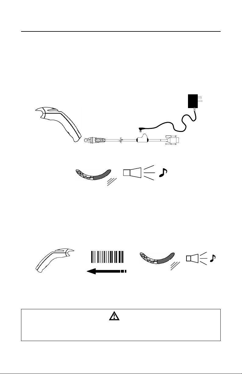
QUICK START
1. Connect the 10-pin RJ45 plug into the jack on the Eclipse MS5145. You
will hear a ‘click’ when the connection is made.
2. Connect the L-shaped plug of the power supply into the power jack on the
PowerLink cable.
3. Connect the power supply into an AC outlet. Make sure the AC input
requirements of the power supply match the AC outlet.
(See caution statement below)
p
no
4. When the MS5145 is ready to scan, the green LED will turn on, the red LED
will flash and the scanner will beep once.
5. The MS5145‘s operation is automatic. The laser pulses on and off. The
green LED remains on during normal pulse operation and it blinks during
power save mode.
Operational Test
6. Place a bar code in front of the scanning window. While aiming at the bar
code with the blinking laser beam, press the CodeGate button, scanner will
beep once and flash the red LED if the bar code was successfully decoded.
s
7. The scanner is shipped from the factory programmed with default settings.
To configure the MS5145 scanner to meet the host system’s specific needs,
refer to the Programming Guide or custom configuration guide for
instructions on how to change the scanners default settings.
Caution:
To maintain compliance with federal regulations 21 CFR, Part 1040.10, section (f)(6) the scanner
must be plugged into an electrical outlet with a switch accessible to the user or be powered by a host
system containing a switch that will disable power to the scanner.
3
Page 8
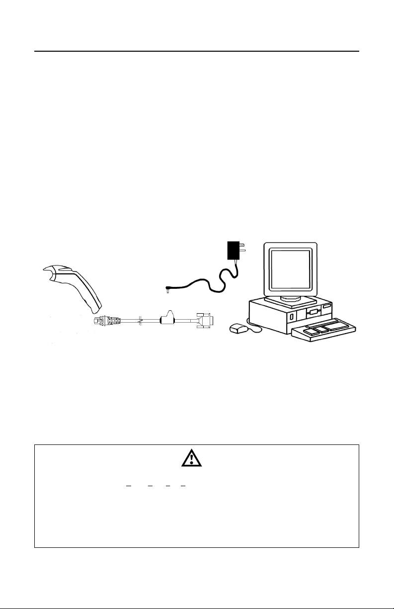
STANDARD RS232 SCANNER INSTALLATION
1. Turn off the host system.
2. Connect the 10-pin RJ45 plug of the PowerLink cable into the jack on the
MS5145 RS232 scanner.
Note: If the MS5145 is receiving power from the host system, skip to step
#5. (See caution statement below*)
3. Connect the L-shaped plug of the power supply into the power jack on the
PowerLink cable. (See caution statement below**)
4. Make sure the AC input requirements of the power supply match the AC
outlet. Connect the power supply into an AC outlet.
5. Connect the PowerLink cable to the proper port on the host system.
6. Turn on the host system
q
s
n
o
7. When the MS5145 is ready to scan, the green LED will turn on, the red LED
will flash and the scanner will beep once.
Manufacturer’s Note:
Plugging the scanner into a port on the host system does not guarantee that the
scanned information will be communicated properly to the host system. The
scanner and/or the host system may need to be configured for communications
to occur.
Caution:
To maintain compliance with applicable standards, all circuits connected to the scanner must meet
the requirements for SELV (Safety Extra Low Voltage) according to EN 60950.
*To maintain compliance with standard CSA C22.2 No. 60950/UL 60950 and norm EN 60950, the
power source should meet applicable performance requirements for a limited power source.
**To maintain compliance with federal regulations 21 CFR, Part 1040.10, section (f)(6) the scanner
must be plugged into an electrical outlet with a switch accessible to the user or be powered by a host
system containing a switch that will disable power to the scanner.
p
r
4
Page 9

KEYBOARD WEDGE SCANNER INSTALLATION
1. Turn off the host system.
2. Connect the 10-pin RJ45 plug of the PowerLink cable into the jack on the
MS5145.
3. Disconnect the keyboard from the host system.
4. Connect the L-shaped plug of the power supply into the power jack on the
PowerLink cable (refer to the manufacturer’s recommendation and Note on
page 6).
5. Make sure the AC input requirements of the power supply match the AC
outlet. Connect the power supply into an AC outlet (see caution statement
on page 6**).
6. The PowerLink “Y” cable is terminated with a 5-pin DIN female connector on
one end, and a 6-pin mini DIN male on t
5
Page 10

KEYBOARD WEDGE INSTALLATION (CONTINUED)
Manufacturer’s Recommendation
If the keyboard port of the host system cannot supply enough current, the use of
an external power supply with the MS5145 Keyboard Wedge will be necessary.
Powering the MS5145 directly from the computer keyboard connector could
interfere with the operation of the scanner or the computer. Not all computers
supply the same current through the keyboard port, so a scanner may work on
one computer and not another (see caution statement on page 5).
Caution:
To maintain compliance with applicable standards, all circuits connected to the scanner must meet
the requirements for SELV (Safety Extra Low Voltage) according to EN 60950.
*To maintain compliance with standard CSA C22.2 No. 60950/UL 60950 and norm EN 60950, the
power source should meet applicable performance requirements for a limited power source.
**To maintain compliance with federal regulations 21 CFR, Part 1040.10, section (f)(6) the scanner
must be plugged into an electrical outlet with a switch accessible to the user or be powered by a host
system containing a switch that will disable power to the scanner
Note: The center of the L-Shaped plug of the power supply is negative (“-“).
6
Page 11
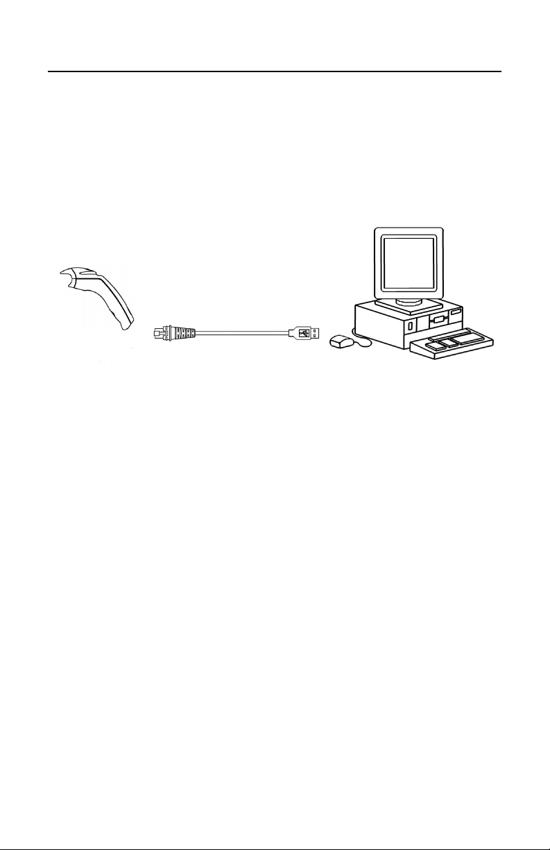
USB SCANNER INSTALLATION
1. Connect the 10-pin RJ45 plug of the PowerLink cable into the jack on the
MS5145 USB scanner.
Note: The MS5145 USB scanner will receive power directly from the host
system; no external power supply is required.
2. Connect the USB connector of the PowerLink cable into the USB port of the
host system.
no
3. When the MS5145 is ready to scan, the green LED will turn on, the red LED
will flash and the scanner will beep once.
7
Page 12
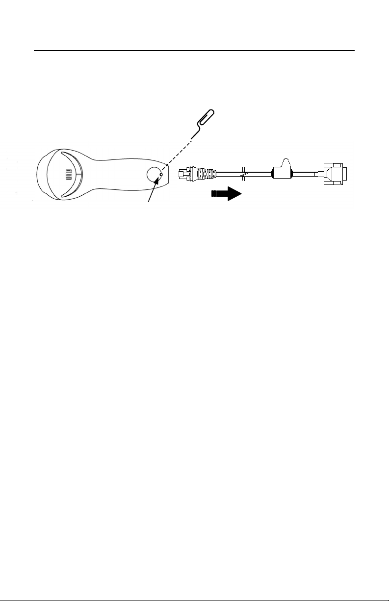
DISCONNECTING THE POWERLINK CABLE FROM THE SCANNER
&
Before removing the cable from the scanner, Metrologic recommends that the
power on the host system is off and the power supply has been disconnected
from the PowerLink cable.
op
q
n
1. Locate the small ‘pin-hole’ on the back of the scanner.
2. Bend an ordinary paperclip into the shape shown above.
3. Insert the paperclip (or other small metallic pin) into the small ‘pin-hole’.
4. You will hear a faint ‘click’. Pull gently on the strain-relief of the PowerLink
cable and it will slide out of the scanner.
8
Page 13

SCANNER PARTS
1. Green & Red LEDs
The MS5145’s laser pulses on and off when no bar code is presented, and
stays on when it senses a bar code. The green LED remains on during
normal pulse and scanning operation, and it blinks during power save mode.
On a successful read of a bar code, the red LED will flash and the scanner
will beep once. The LEDs are also used as diagnostic indicators and mode
indicators.
2. Output Window
Laser Light emits from this aperture.
3. PowerLink Cable
The 10-pin modular plug on the PowerLink cable connects into the 10-pin
modular jack on the MS5145.
9
Page 14

AUDIBLE INDICATORS
When the MS5145 scanner is operational, it provides audible feedback. These
sounds indicate the status of the scanner. Eight settings are available for the
tone of the beep (normal, 6 alternate tones and no tone). To change the tone,
refer to the Configuration Guide.
One Beep – on power up
The green LED will turn on, then the red LED will flash and the
scanner will beep once. The red LED will remain on for the
duration of the beep. The scanner is now ready to scan.
One Beep – during operation
When the scanner successfully reads a bar code, the red LED
will flash and the scanner will beep once (if programmed to do
so). If the scanner does not beep once and the red light does
not flash, then the bar code has not been successfully read.
Three Beeps – during operation
When entering the program mode, the red LED will flash while
the scanner simultaneously beeps three times. The red LED
will continue to flash until the unit exits program mode. Upon
exiting program mode, the scanner will beep three times and
the red LED will stop flashing.
10
When configured for communication timeout, 3 beeps during
operation will indicate that a communication timeout has
occurred.
Three Beeps – on power up
This is a failure indicator. Refer to the Failure Modes section
of this guide on page 11.
Razzberry Tone
This is a failure indicator or an invalid code read during
program mode. Refer to the Failure Modes section of this
guide on page 12.
Page 15

VISUAL INDICATORS
There is a red LED and a green LED on the MS5145. When the scanner is on,
the activity of the LEDs indicates the status of the current scan and the scanner.
Green and Red LEDs are off
The LEDs will not be illuminated if the scanner is not receiving
power from the host or transformer.
Steady Green
Indicates normal pulse or continuous laser operation.
Accompanied by a razzberry tone, it indicates that an invalid
bar code has been scanned.
Flashing Green
After a period of inactivity, the ON time of the pulsing laser will
be shortened. During this time the green LED will flash. This
indicates that the scanner is in a power saver mode. When a
bar code enters the laser field, the scanner will wake up and
return to normal pulse mode.
Steady Green and Single Red Flash
When the scanner successfully reads a bar code, the red LED
will flash and the scanner will beep. If the red LED does not
flash and the scanner does not beep, then the bar code has
not been successfully read.
Steady Green and Steady Red
After a successful read, the scanner transmits the data to the
host device. Some communication modes require that the host
inform the scanner when data is ready to be received. If the
host is not ready to accept the information, the scanner’s red
LED will remain on until the data can be transmitted.
Steady Green and Continuous Flashing Red
When entering the program mode, the red LED will flash, the
green LED will turn on and the scanner will beep three times.
The red LED will continue to flash and the green LED will stay
on until the unit exits the program mode.
11
Page 16

FAILURE MODES
One Razzberry Tone on Power-up
This indicates the scanner has experienced a laser or flipper
subsystem failure. Return the unit for repair to a Metrologic
Authorized Service Center.
Continuous Razzberry Tone with all LEDs off
If, upon power up, the scanner emits a continuous razzberry
tone, then the scanner has an experienced an electronic
failure. Return the unit for repair to a Metrologic Authorized
Service Center.
Three Beeps – on power up
If the scanner beeps 3 times on power up then, the non-volatile
memory (NovRAM) that holds the scanner configuration has
failed. Return the unit for repair to a Metrologic Authorized
Service Center.
12
Page 17

SCAN AREA
Minimum Bar Code Element Width
ABCDEF
mm .10 .12 .17 .26 .33 .66
mils 4.1 4.8 6.8 10.4 13 26
13
Page 18

LABELS
Each scanner has one label on the underside of the unit. This label has the
model number, date of manufacture, serial number, laser and caution
information. The following is an example of this label.
Patent Information-See Manual
FCC and ICES-003 Information-See Manual
Warranty VOID if case opened.
Contains no user serviceable components.
Complies with 21 CFR 1040.10 & 1040.11
IEC 60825-1:1993+A2:2001
14
Page 19

TROUBLESHOOTING GUIDE
The following guide is for reference purposes only. Contact a Metrologic
representative to preserve the limited warranty terms on page 31.
SYMPTOMS POSSIBLE CAUSE(S)SOLUTION
Check transformer,
No LEDs, beep
or laser line
No LEDs, beep
3 beeps on
power up
No power is being supplied to
the scanner
No power is being supplied to
the scanner from host
Non-volatile RAM failure
outlet and power strip.
Make sure the cable is
plugged into the
scanner.
Some host systems
cannot supply enough
current to power the
MS5145. Use the
proper power supply.
Contact a Metrologic
Representative, if the
unit will not hold the
programmed
configuration.
Continuous razz
tone on power up
Razz tone at
power up
Unit scans,
Communicates
and beeps twice
The unit powers
up but does not
beep
RAM or ROM failure
VLD failure or a Scanner
flipper failure
Same Symbol timeout set too
short
Beeper disabled. No tone
selected
Contact a Metrologic
Representative.
Contact a Metrologic
Representative.
Adjust same symbol time
out for a longer time.
Enable beeper. Select
tone.
15
Page 20

TROUBLESHOOTING GUIDE (CONTINUED)
SYMPTOMS POSSIBLE CAUSE(S)SOLUTION
UPC/EAN, Code 39,
The unit powers
up, but does not
scan
Scanning a particular
symbology that is not
enabled
Interleaved 2 of 5, Code 93,
Code 128 and Codabar are
enabled by default. Verify that
the type of bar code being
read has been selected.
The unit powers
up, but does not
scan and/or beep
The unit scans a
bar code, but
locks up after the
first scan and the
red LED stays on
The unit scans,
but the data
transmitted to the
host is incorrect
Scanner beeps
at some bar
codes and NOT
for others of the
same bar code
symbology
The scanner has been
programmed for a
character length lock, or
a minimum length and
bar code being scanned
does not satisfy the
programmed criteria
The scanner is
configured to support
some form of host
handshaking but is not
receiving the signal
The scanner’s data
format does not match
the host system
requirements
The print quality of the
bar code is suspect
Or
The aspect ratio of the
bar code is out of
tolerance
Verify that the bar code that is
being scanned falls into the
criteria (Typical of Non-
UPC/EAN codes.) The
scanner defaults to a minimum
of 3 character bar code.
If the scanner is setup to
support ACK/NAK,RTS/CTS,
XON/XOFF) or D/E, verify that
the host cable and host are
supporting the handshaking
properly.
Verify that the scanner’s data
format matches that required
by the host. Make sure that the
scanner is connected to the
proper host port.
Check print mode. The type of
printer could be the problem.
Change print settings. For
example change to econo
mode or high speed.
16
Page 21

TROUBLESHOOTING GUIDE (CONTINUED)
SYMPTOMS POSSIBLE CAUSE(S)SOLUTION
Scanner beeps
at some bar
codes and NOT
for others of the
same bar code
symbology
Scanner beeps
at some bar
codes and NOT
for others of the
same bar code
symbology
Scanner beeps
at some bar
codes and NOT
for others of the
same bar code
symbology
The bar code may have
been printed incorrectly
The scanner is not
configured correctly for
this type of bar code
The minimum symbol
length setting does not
work with the bar code
Check if it is a check
digit/character/or border
problem.
Check if check digits are set
properly.
Check if the correct minimum
symbol length is set.
The unit scans
the bar code but
there is no data
The unit scans
but the data is
not correct
(Keyboard
Wedge)
Configuration is not
correct
Configuration is not
correct
Make sure the scanner is
configured for the appropriate
communication mode.
Make sure that the proper PC
type AT, PS2 or XT is
selected. Verify correct country
code and data formatting are
selected. Adjust intercharcter
delay.
17
Page 22

TROUBLESHOOTING GUIDE (CONTINUED)
SYMPTOMS POSSIBLE CAUSE(S)SOLUTION
The unit is not
transmitting each
character
(Keyboard
Wedge)
Alpha characters
show as lower
case (Keyboard
Wedge)
Everything works
except for a
couple of
characters
(Keyboard
Wedge)
Power-up OK
and scans OK
but does not
communicate
properly to the
host
Configuration is not
correct
Computer is in Caps
Lock mode
These characters may
not be supported by that
country’s key lookup
table
Com port at the host is
not working or
configured properly
or
Cable not connected to
the proper comm port
Increase interscan code delay
setting. Adjust whether the F0
break is transmitted. It may be
necessary to try this in both
settings.
Enable Caps Lock detect
setting of the scanner to detect
whether the PC is operating in
Caps Lock.
Try operating the scanner in
Alt mode.
Check to make sure that the
baud rate, data bits, stop bits
and parity of the scanner and
the communication port match
and the program is looking for
“RS-232” data.
The host is
receiving data
but the data does
not look correct
Characters are
being dropped
18
The scanner and host
may not be configured
for the same interface
font
Scanner may not be set
for sufficient Inter-
character delay
Check that the scanner and
the host are configured for the
same interface font.
Add some inter-character
delay to the transmitted output
by using the MetroSelect
Programming Guide MLPN
2544.
Page 23

RS-232 DEMONSTRATION PROGRAM
If an RS-232 scanner is not communicating with your IBM compatible PC, key in
the following BASIC program to test that the communication port and scanner are
working. This program is for demonstration purposes only. It is only intended to
prove that cabling is correct, the communication port is working, and the scanner
is working. If the bar code data displays on the screen while using this program,
it only demonstrates that the hardware interface and scanner are working. At this
point, investigate whether the application software and the scanner configuration
match. If the application does not support RS-232 scanners, a software wedge
program that will take RS-232 data and place it into a keyboard buffer may be
needed. This program tells the PC to ignore RTS-CTS, Data Set Ready (DSR)
and Data Carrier Detect (DCD) signals. If the demonstration program works and
yours still does not, jumper RTS to CTS and Data Terminal Ready (DTR) to DCD
and DSR on the back of your PC.
10 CLS
20 ON ERROR GOTO 100
30 OPEN “COM1:9600,S,7,1,CS0,DS0,CD0,LF” AS #1
35 PRINT “SCAN A FEW BAR CODES”
40 LINE INPUT #1, BARCODE$
50 PRINT BARCODE$
60 K$ = INKEY$: IF K$ = CHR$(27) THEN GOTO 32766
70 GOTO 40
100 PRINT “ERROR NO.”; ERR; “ PRESS ANY KEY TO TERMINATE.”
110 K$ = INKEY$: IF K$ = “” THEN GOTO 110
32766 CLOSE: SYSTEM
32767 END
MAINTENANCE
Smudges and dirt on the window of the scanner can interfere with proper
scanning. Therefore, the output window will need occasional cleaning.
1. Spray glass cleaner onto a lint-free, non-abrasive cleaning cloth.
2. Gently wipe the scanner window.
19
Page 24

APPENDIX A
Specifications
OPERATIONAL
Light Source
Laser Power (peak) <1.0 mW
Depth of Scan Field
(for 13mil at Default)
Scan Speed 72 ± 2 scan lines per second
Scan Pattern Single scan line
Minimum Bar Width 0.102 mm (4.0 mil)
Decode Capability
System Interfaces
Print Contrast 35% minimum reflectance difference
Number Characters
Read
Roll, Pitch, Yaw 42°, 68°, 52°
Beeper Operation 7 tones or no beep
Indicators (LED)
Visible Laser Diode 650 nm ± 10 nm
0 mm – 140 mm (0” – 5.5”)
Autodiscriminates all standard bar codes; for others
call Metrologic
RS232, Keyboard Wedge, Light Pen Emulation, IBM
468X/469X, OCIA, Stand Alone Keyboard, USB
Up to 80 data characters
(Maximum number will vary based on symbology and
density)
Green = laser on, ready to scan
Red = good read
MECHANICAL
Length 170 mm (6.7”)
Width-Handle
Width-Head
Height-Head
Height-Handle
Weight 97 g (3.4 oz)
Cable Long bend relief PowerLink Cable (see Page 2)
20
39 mm (1.5”)
63 mm (2.5”)
35 mm (1.4”)
31 mm (1.2”)
Page 25

APPENDIX A (CONTINUED)
ELECTRICAL
Input Voltage 5 VDC ± 0.25 V
Power - Operating 0.675 mW
Current - Operating 135 mA peak @ 5 VDC
DC Transformers Class 2; 5.2 V @ 650 mA
UL
Laser Class
EMC
UL listed for US and Canada;
UL 60950, C22.2 No. 60950
CDRH: Class II; IEC 60825-1:
1993+A1:1997+A2:2001 Class 1
Class B: FCC Part 15, ICES-003, European Union
Directive
ENVIRONMENTAL
Operating
Temperature
Storage Temperature -40°C to 60°C (-40°F to 140°F)
Humidity 5% to 95% relative humidity, non-condensing
Light Levels Up to 4842 Lux (450 footcandles)
Shock Designed to withstand 1.5 m (5’) drops
Contaminants Sealed to resist airborne particulate contaminants
Ventilation None required
0°C to 40°C (32°F to 104°F)
21
Page 26
APPENDIX B
Default Settings
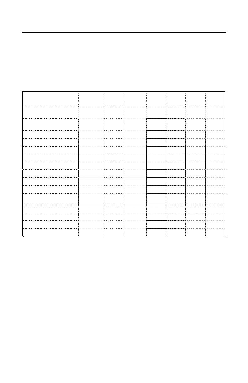
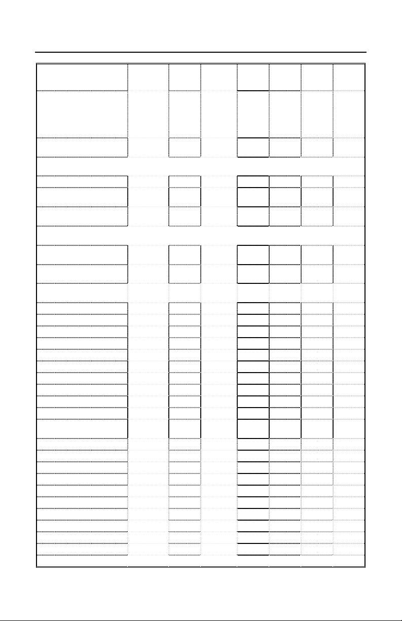
Many functions of the scanner can be “programmed” – that is, enabled or disabled. The
scanner is shipped from the factory programmed to a set of default conditions. The default
parameter of the scanner has an asterisk (*) in the charts on the following pages. If an
asterisk is not in the default column then the default setting is OFF or DISABLED. Every
communication does not support every parameter. If the communication supports a
parameter listed in the charts on the following pages, a check mark will appear.
Parameter Default OCIA RS232
Normal Scan Mode
(Blink)
Continuous Scan
Mode
UPC/EAN * 9 9 9999
UPC-A *
EAN-8 * 9 9 9999
EAN-13 * 9 9 9999
UPC-E *
Code 128 * 9 9 9999
Code 93 * 9 9 9999
Codabar *
Interleaved 2 of 5
(ITF)
MOD 10 check on ITF 9 9 9999
Code 11 9 9 9999
Code 39 *
Full ASCII Code 39 9 9 9999
Telepen 99
*
*
9 9 9999
9 9 9999
9 9 9999
9 9 9999
9 9 9999
9 9 9999
9 9 9999
Light
Pen
As Code
IBM
46XX
39
KBW USB
999
22
Page 27

APPENDIX B (CONTINUED)
Parameter Default OCIA RS232
Paraf Support ITF
ITF Symbol Lengths Variable 9 9 9999
Minimum Symbol
Length
Symbol Length Lock None 9 9 9999
Bars High as Code 39 *
Spaces High as Code
39
Bars High as
Scanned
Spaces High as
Scanned
Low Speed Option 9
Toggle on Decode
10x Narrow Element * 9
50x Narrow Element 9
Poll Light Pen Source
Beeper Tone Normal 9 9 9999
Beep/Transmit
Sequence
Communication
Timeout
Razzberry tone on
Timeout
Three beeps on
Timeout
Same symbol rescan
timeout 100 msecs
Same symbol rescan
timeout 200 msecs
Same symbol rescan
timeout 500 msecs
Same symbol rescan
timeout 1200 msecs
Same symbol rescan
timeout 2000 msecs
No Same Symbol
Timeout
Extra Same Symbol
Check
Normal Same Symbol
Check
Infinite Same Symbol
Timeout
Number of scan
buffers
(maximum)
3
Before
transmit
none
*
*
2
9 9 9999
9 9 9999
9999 9
9 9 999
9 9 999
9 9 999
9 9 9999
9 9 9999
9 9 9999
9 9 9999
9 9 9999
9 9 9999
9 9 9999
9 9 9999
9 9 9999
9 9 9999
Light
Pen
IBM
46XX
9
9
9
9
9
9
KBW USB
23
Page 28
APPENDIX B (CONTINUED)
Parameter Default OCIA RS232
Inter-character delay
Programmable in 1
msec steps (max 255
msecs)
Transmit UPC-A
check digit
Transmit UPC-E
check digit
Expand UPC-E 9 9 9999
Convert UPC-A to
EAN-13
Transmit lead zero on
UPC-E
Transmit UPC-A
number system
Transmit UPC-A
Manufacturer ID#
Transmit UPC-A Item
ID#
Transmit Codabar
Start/Stop Characters
CLSI Editing (Enable) 99 9 9
Transmit Mod 10/ITF 99 9 9
Transmit MSI-Plessy
Parity Space 99
Baud Rate 9600 9
8 Data Bits
7 Data Bits * 9
Stop Bits 2 99
Manufacturer’s ID
Scanner ID 999
Transmit Sanyo ID
Characters
Nixdorf ID 999
Aim ID
Sineko ID 999
Sni Beetle ID 999
Tec ID
NCR ID 999
Rochford Thomson ID 999
Family Dollar ID
LRC Enabled 999
UPC Prefix 999
UPC Suffix
1
msecs
10
msecs
in KBW
*
*
*
*
9 9 999
9 9 9999
9 9 9999
9 9 9999
9 9 9999
9999 9
9999 9
9999 9
99 9 9
99 9 9
Light
Pen
99
999
999
999
999
999
999
IBM
46XX
KBW USB
24
Page 29

APPENDIX B (CONTINUED)
Parameter Default OCIA RS232
Light
Pen
IBM
46XX
KBW USB
Carriage Return * 999
Line Feed-Disabled
by default in KBW
Tab Prefix
*
99
99
Tab Suffix 99
“C” prefix 99
“I” prefix
99
STX prefix 99
ETX suffix 999
“DE” Disable
Command
“FL” Laser
Commands
DTR Handshaking
support
RTS/CTS
Handshaking
Character RTS/CTS *
9
9
9
9
9
Message RTS/CTS 9
XON/XOFF
Handshaking
9
ACK/NAK 9
Two Digit
Supplements
Five Digit
Supplements
Bookland (978)
99
99
99
As Code
39
As Code
39
As Code
39
999
999
999
977 (2 digit)
Supplemental
9 9 9999
Requirement
Supplements are not
Required
*
9 9 9999
25
Page 30

APPENDIX B (CONTINUED)
Parameter Default OCIA RS232
Coupon Code 128 99
Programmable Code
Lengths
Programmable Suffix
Characters
Prefixes for Individual
Code types
Inter Scan-Code
Delay Programmable
(100 µsec steps)
7 avail
10 avail
800
µsec
9 9 9999
999
999
Function/Control Key
Support
Minimum Element
Width Programmable
1 msec. 9
in 5.6 µsec steps
Country Coded
Keyboards
US
Light
Pen
As Code
39
IBM
46XX
KBW USB
999
9
99
99
26
Page 31

APPENDIX C
Scanner Pinout Connections
MS5145-41 (RS-232C & LTPN)
Pin Function
1 Ground
2 RS-232 Transmit Output
3 RS-232 Receive Input
27
Page 32

APPENDIX C (CONTINUED)
MS5145-37 (USB/KBW)
Pin Function
1 Ground
2D-
3D+
4 PC DATA
5 PC CLOCK
6 KB CLOCK
7 PC+5V/V_USB
8 KB DATA
9V_EXT
10 Shield Ground
Cable Connector Configurations
• RS232 PowerLink Cable with built in power jack [ MLPN 55-55000A ]
The RS232 PowerLink cable is terminated with a 9-pin D-Type connector to
the host.
“Standard” PowerLink cable
28
Pin Function
1 Shield Ground
2 RS-232 Transmit Output
3 RS-232 Receive Input
4 DTR Input/Light Pen Source
5 Power/Signal Ground
6 Light Pen Data
7 CTS Input
8 RTS Output
9 +5VDC*
Page 33

APPENDIX C (CONTINUED)
p
• Keyboard Wedge PowerLink and Adapter Cable [MLPN 55-55002A]
The Keyboard Wedge PowerLink cable is a “Y” cable terminated with a 5-pin DIN
female connector on one end, and a 6-pin mini DIN male on the other.
2
5
4
1
3
Keyboard Wedge
PowerLink Cable
5-Pin DIN, Female
Metrologic will supply an adapter cable with a 5-pin DIN male connector on one
end and a 6-pin mini DIN female connector on the other.
2
4
5
3
5-Pin Din, Male
1
ter Cable
Ada
6-pin Mini Din, Female
According to the termination required, connect the appropriate end of the adapter
cable to the PowerLink cable, leaving the necessary termination exposed for
connecting to the keyboard and the keyboard port on the PC.
The pin assignments of the Keyboard Wedge PowerLink and adapter cable ar e as
follows:
21
4
3
5
6
6-Pin DIN, Male
2
1
3
4
6
5
POWERLINK CABLE ADAPTER CABLE
5-pin Female DIN 5-pin Male DIN
Pin Function Pin Function
1 Keyboard Clock 1 PC Clock
2 Keyboard Data 2 PC Data
3 No Connect 3 No Connect
4 Power Ground 4 Power Ground
5 +5 Volts DC 5 +5 Volts DC
6-pin Male Mini-DIN 6-pin Female Mini-DIN
Pin Function Pin Function
1 PC Data 1 Keyboard Data
2 No Connect 2 No Connect
3 Power Ground 3 Power Ground
4 +5 Volts DC 4 +5 Volts DC
5 PC Clock 5 Keyboard Clock
6 No Connect 6 No Connect
29
Page 34

APPENDIX C (CONTINUED)
• USB PowerLink cable [ MLPN 55-55165A ]
The USB PowerLink cable is terminated with an USB A type connector.
USB PowerLink cable
Pin Function
1 PC+5V/V_USB
2D-
3D+
USB A Type Connector
4 Ground
30
Page 35

APPENDIX D
Warranty and Disclaimer
Limited Warranty
The MS5145 scanner is manufactured by Metrologic at its Suzhou, China facility. The
MS5145 scanners have a two (2) year limited warranty from the date of manufacture.
Metrologic warrants and represents that all MS5100 scanners are free of all defects in
material, workmanship and design, and have been produced and labeled in compliance
with all applicable U.S. Federal, state and local laws, regulations and ordinances pertaining
to their production and labeling.
This warranty is limited to repair, replacement of Product or refund of Product price at the
sole discretion of Metrologic. Faulty equipment must be returned to Metrologic. To do this,
contact Metrologic’s Customer Service/Repair Department to obtain a Returned Material
Authorization (RMA) number.
In the event that it is determined the equipment failure is covered under this warranty,
Metrologic shall, at its sole option, repair the Product or replace the Product with a
functionally equivalent unit and return such repaired or replaced Product without charge
for service or return freight, whether distributor, dealer/reseller, or retail consumer, or
refund an amount equal to the original purchase price.
This limited warranty does not extend to any Product which, in the sole judgement of
Metrologic, has been subjected to abuse, misuse, neglect, improper installation, or
accident, nor any damage due to use or misuse produced from integration of the Product
into any mechanical, electrical or computer system. The warranty is void if the case of
Product is opened by anyone other than Metrologic’s repair department or authorized
repair centers.
THIS LIMITED WARRANTY, EXCEPT AS TO TITLE, IS IN LIEU OF ALL OTHER WARRANTIES OR
GUARANTEES, EITHER EXPRESS OR IMPLIED, AND SPECIFICALLY EXCLUDES, WITHOUT
LIMITATION, WARRANTIES OF MERCHANTABILITY AND FITNESS FOR A PARTICULAR
PURPOSE UNDER THE UNIFORM COMMERCIAL CODE, OR ARISING OUT OF CUSTOM OR
CONDUCT. THE RIGHTS AND REMEDIES PROVIDED HEREIN ARE EXCLUSIVE AND IN LIEU OF
ANY OTHER RIGHTS OR REMEDIES. IN NO EVENT SHALL METROLOGIC BE LIABLE FOR ANY
INDIRECT OR CONSEQUENTIAL DAMAGES, INCIDENTAL DAMAGES, DAMAGES TO PERSON
OR PROPERTY, OR EFFECT ON BUSINESS OR PROPERTY, OR OTHER DAMAGES OR
EXPENSES DUE DIRECTLY OR INDIRECTLY TO THE PRODUCT, EXCEPT AS STATED IN THIS
WARRANTY. IN NO EVENT SHALL ANY LIABILITY OF METROLOGIC EXCEED THE ACTUAL
AMOUNT PAID TO METROLOGIC FOR THE PRODUCT. METROLOGIC RESERVES THE RIGHT
TO MAKE ANY CHANGES TO THE PRODUCT DESCRIBED HEREIN.
North America Headquarters
Metrologic Instruments, Inc. Customer Service: 1-800-ID-METRO
90 Coles Road Tel: 856-228-8100
Blackwood, NJ 08012-4683 Fax: 856-228-6673
China Facility
Metro (Suzhou) Technologies Co., Ltd Tel: 86-512-2572511
221 Xing Hai Street Fax: 86-512-2571517
Suzhou Industrial Park Email: info@cn.metrologic.com
Suzhou, China 215021
Email: info@metrologic.com
Website: www.metrologic.com
31
Page 36

APPENDIX E
Notice
This equipment has been tested and found to comply with the limits for a Class B digital device,
pursuant to Part 15 of the FCC rules. These limits are designed to provide reasonable protection against
harmful interference in a residential installation. This equipment generates, uses and can radiate radio
frequency and, if not installed and used in accordance with the instruction, may cause harmful
interference to radio communications. However, there is no guarantee that interference will not occur in
a particular installation. If this equipment does cause harmful interference to radio or television
reception, which can be determined by turning the equipment off and on, the user is encouraged to try to
correct the interference by one or more of the following measures:
• Reorient or relocate the receiving antenna
• Increase the separation between the equipment and receiver
• Connect the equipment into an outlet on a circuit different from that to which the receiver is
connected
• Consult the dealer or an experienced radio TV technician for help
Changes or modifications not expressly approved by the party responsible for compliance could void the
user’s authority to operate the equipment.
This device complies with Part 15 of the FCC Rules. Operation is subject to the following two
conditions: (1) This device may not cause harmful interference, and (2) this device must accept any
interference received, including interference that may cause undesired operation.
Notice
This Class B digital apparatus complies with Canadian ICES-003.
Caution
Use of controls or adjustments or performance of procedures other than those specified herein may
result in hazardous laser light exposure. Under no circumstances should the customer attempt to
service the laser scanner. Never attempt to look at the laser beam, even if the scanner appears to be
nonfunctional. Never open the scanner in an attempt to look into the device. Doing so could result in
hazardous laser light exposure. The use of optical instruments with the laser equipment will increase
eye hazard.
Remarque
Cet appareil numerique de la class B est conforme à la norme NMB-003 du Canada.
Attention
L'emploi de commandes, réglages ou procédés autres que ceux décrits ici peut entraîner de graves
irradiations. Le client ne doit en aucun cas essayer d'entretenir lui-même le scanner ou le laser. Ne
regardez jamais directement le rayon laser, même si vous croyez que le scanner est inactif. N'ouvrez
jamais le scanner pour regarder dans l'appareil. Ce faisant, vous vous exposez à une rayonnement
laser mortel. L'emploi d'appareils optiques avec cet équipement laser augmente le risque
d'endommagement de la vision.
Achtung
Die Verwendung anderer als der hier beschriebenen Steuerungen, Einstellungen oder Verfahren kann
eine lebensgefährliche Laserstrahlung hervorrufen. Der Kunde sollte unter keinen Umständen
versuchen, den Laser-Scanner selbst zu warten. Sehen Sie niemals in den Laserstrahl, selbst wenn Sie
glauben, daß der Scanner nicht aktiv ist. Öffnen Sie niemals den Scanner, um in das Gerät
hineinzusehen. Wenn Sie dies tun, können Sie sich einer lebensgefährlichen Laserstrahlung aussetzen.
Der Einsatz optischer Geräte mit dieser Laserausrüstung erhöht das Risiko einer Sehschädigung.
Attenzione
L’utilizzo di sistemi di controllo, di regolazioni o di procedimenti diversi da quelli descritti nel presente
Manuale può provocare dei raggi laser pericolosi per la vita. Il cliente non deve assolutamente tentare di
riparare egli stesso lo scanner laser. Non guardate mai nel raggio laser, anche se credete che lo
scanner non sia attivo. Non aprite mai lo scanner per guardare dentro l’apparecchio. Se tuttavia lo fate,
potete esporVi a dei raggi laser pericolosi per la vita. L’uso di apparecchi ottici con questo
equipaggiamento laser aumenta il rischio di danni alla vista.
32
Page 37

APPENDIX F
Patent Information
“This METROLOGIC product may be covered by one or more of the following
U.S. Patents:
U.S. Patent No.;
5,260,553; 5,340,971; 5,424,525; 5,484,992; 5,525,789; 5,528,024;
5,616,908; 5,627,359; 5,661,292; 5,777,315; 5,789,730; 5,789,731;
5,811,780; 5,828,048; 5,925,870; 6,029,894; 6,209,789; 6,227,450;
6,283,375;
No license right or sublicense is granted, either expressly or by implication,
estoppel, or otherwise, under any METROLOGIC or third party intellectual
property rights (whether or not such third party rights are licensed to
METROLOGIC), including any third party patent listed above, except for an
implied license only for the normal intended use of the specific equipment,
circuits, and devices represented by or contained in the METROLOGIC products
that are physically transferred to the user, and only to the extent of
METROLOGIC’S license rights and subject to any conditions, covenants and
restrictions therein.”
Other worldwide patents pending.
33
Page 38

INDEX
A
AC input/outlet ................... 2, 3, 4, 6
Accessories ................................... 2
Approvals ........................ 13, 20, 30
Assignments
pin ...................... 2, 4, 6, 7, 26, 27
Audible .............................. 9, 11, 19
Autodiscriminates ........................ 19
B
Bar code ... 1, 3, 8-10, 15, 16, 18, 19
Bar width ..................................... 12
Beep ......3, 4, 6, 8-11, 14-16, 19, 22
C
Cable .....1-4, 6-8, 14, 17, 19, 26, 27
communication. 17, 18, 21, 26, 2 7
detachable ................... 1, 2, 7, 27
pin assignments ................. 26, 27
powerlink..............1-4, 6-8, 26, 27
Caution .......................... 4, 6, 13, 30
CDRH .......................................... 20
CodeGate…………………….1,3,8
Communication ........ 4, 9, 10, 17-22
Compliance ................... 4, 6, 28, 30
Configuration . 1, 2, 9, 11, 14, 1 8, 26
Current .............................. 6, 14, 20
Customer service .................... 2, 28
F
Failure indicator(s) ............ 9, 11, 14
Failure modes ............................. 11
G
Green LED ................ 3, 4, 8, 10, 19
H
Host .......... 3, 4, 6, 7, 10, 14, 17, 26
I
Indicators ...................... 8, 9, 10, 19
Input voltage ....................... 4, 6, 20
Installation....................... 2, 4, 6, 28
Interfaces .......................... 1, 19, 26
K
Keyboard wedge . 1, 2, 6, 19, 26, 27
L
Labels ......................................... 13
Light levels .................................. 20
Light pen ............... 1, 19, 21, 22, 26
Light source ................................ 19
D
DC transformer ............................20
Decode capability ........................ 19
Default settings........................ 3, 21
Depth of field .................................1
Design specifications................... 19
Disclaimer.................................... 28
E
Electrical power supply... 3-7, 14, 26
34
M
Maintenance ............................... 13
N
Notices ........................................ 30
O
Operating current ........................ 20
Operating temperture .................. 20
Output window .................. 8, 12, 13
Page 39

INDEX
P
Parts .......................................... 2, 8
Power supply............... 3, 4, 6, 7, 26
Programming modes ......... 3, 17, 18
Q
Quick start .....................................3
R
Razzberry tone ............ 9, 10, 11, 22
Red LED.................. 3, 4, 6, 8, 9, 10
Repair.................................... 11, 28
RMA ............................................ 28
RS-232 ............ 1, 17, 18, 19, 21, 26
S
Scan lines ....................................19
Scan speed ................................. 19
SELV ......................................... 4, 6
Service .................................. 11, 28
Specifications .............................. 19
T
Tones ...................................... 9, 19
Transformers............................... 20
Troubleshooting ........ 14, 15, 16, 17
U
USB .................................... 1,28,30
V
Ventilation ................................... 20
Visual .......................................... 10
Voltage........................................ 20
W
Warranty ..................................... 28
Weight......................................... 19
Window ............................... 3, 8, 13
35
Page 40

June 2002
70 - 79001B
 Loading...