

R621-11,R611-51,R641-13,R641-14,R641-15,R641-17,R641-1G,R641-1E,R641-1J,R641-53,R641-55,R612-51,R642-53,R642-55
Metrobility R621-11,R611-51,R641-13,R641-14,R641-15,R641-17,R641-1G,R641-1E,R641-1J,R641-53,R641-55,R612-51,R642-53,R642-55 User guide
RADIANCE
10/100MBPS
INTERFACE LINE CARDS
10/100
PWR
RX
M
M
LK
TX
x
II
RX
LK
T
X
TX
100 FD
10/100
PWR
100 FD
RX
T
X
LK
x
II
TX
RX
M
LK
M
TX
FX
10/100
PWR
FL
100 FD
RX
T
X
LK
x
TX
II
RX
M
LK
M
TX
10/100
PWR
100 FD
RX
T
X
LK
x
II
TX
RX
M
LK
M
TX
FX
10/100
PWR
100 FD
RX
T
X
LK
x
II
TX
RX
S
LK
M
TX
FX
10/100
PWR
FL
RX
M
M
LK
TX
RX
M
LK
M
TX
FX
10/100
PWR
FX
PWR
100 FD
RX
LK
TX
RX
LK
TX
M
M
M
M
10/100
RX
T
X
LK
x
II
TX
RX
M
LK
M
TX
FX
10/100
PWR
FL
FX
PWR
100 FD
RX
LK
TX
RX
LK
TX
RX
T
X
LK
x
II
TX
RX
E
LK
L
H
TX
FX
10/100
100 FD
T
X
x
II
L
H
10/100
100 FD
T
X
x
II
x
II
T
X
100 FD
PWR
RX
LK
TX
RX
LK
TX
FX
Installation & User Guide
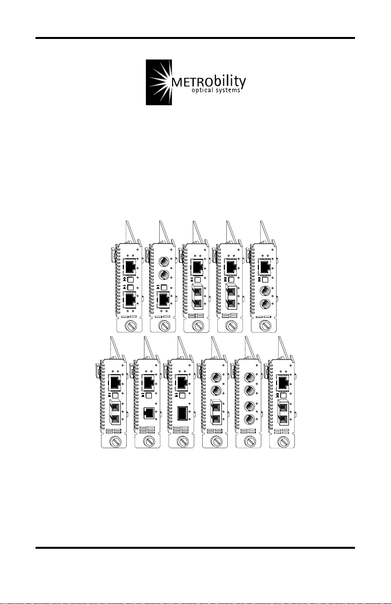
Models:R621-1 1 / R611-51 / R641-13 / R641-14 / R641-15 /
R641-17 / R641-1G / R641-1E / R641-1J / R641-53 /
R641-55 / R612-51 / R642-53 / R642-55

Radiance 10/100Mbps Interface Line Cards
Copper to Copper:
R621-11 ____ 10/100Base-TX to 10/100Base-TX
Copper to Fiber:
R641-13 ____ 10/100Base-TX to 100Base-FX multimode SC
R641-14 ____ 10/100Base-TX to 100Base-FX singlemode SC
R641-15 ____ 10/100Base-TX to 100Base-FX multimode ST
R641-17 ____ 10/100Base-TX to 100Base-FX singlemode SC (40km)
R641-1E____ 10/100Base-TX to 100Base-FX multimode MT-RJ
R641-1G ___ 10/100Base-TX to 100Base-FX multimode VF-45
R641-1J ____ 10/100Base-TX to 100Base-FX singlemode SC (100km)
R611-51 ____ 10Base-FL multimode ST to 10/100Base-TX
Copper to Fiber with LLCF:
R612-51 ____ 10Base-FL multimode ST to 10/100Base-TX
Fiber to Fiber:
R641-53 ____ 10Base-FL multimode ST to 100Base-FX multimode SC
R641-55 ____ 10Base-FL multimode ST to 100Base-FX multimode ST
Fiber to Fiber with LLCF:
R642-53 ____ 10Base-FL multimode ST to 100Base-FX multimode SC
R642-55 ____ 10Base-FL multimode ST to 100Base-FX multimode ST
This publication is protected by the copyright laws of the United States and other countries, with all rights
reserved. No part of this publication may be reproduced, stored in a retrieval system, translated,
transcribed, or transmitted, in any form, or by any means manual, electric, electronic, electromagnetic,
mechanical, chemical, optical or otherwise, without prior explicit written permission of Metrobility Optical
Systems, Inc.
© 2002 Metrobility Optical Systems, Inc. All rights reserved. Printed in USA.

Table of Contents
Radiance 10/100Mbps Interface Line Cards Installation &
User Guide
Overview...............................................................................................................4
Installation Guide ................................................................................................6
STEP 1: Unpack the Line Card ..............................................................6
STEP 2: Set the Switches .......................................................................6
STEP 3: Install the Line Card .............................................................. 12
STEP 4: Connect to the Network ......................................................... 13
User Guide .........................................................................................................15
LED Indicators .....................................................................................15
Factory Settings....................................................................................16
Link Loss Return (LLR) ...................................................................... 17
Link Loss Carry Forward (LLCF) ....................................................... 18
Topology Solutions ..............................................................................19
Technical Specifications.......................................................................20
Product Safety, EMC and Compliance Statements ..............................22
Warranty and Servicing ........................................................................ 23
Metrobility Optical Systems, the Metrobility Optical Systems logo, AutoTwister, NetBeacon and
WebBeacon are trademarks of Metrobility Optical Systems, Inc. All others are trademarks of their
respective owners.
The information contained in this document is assumed to be correct and current. The manufacturer is
not responsible for errors or omissions and reserves the right to change specifications at any time
without notice.

Overview
The Radiance 10/100Mbps interface line card provides seamless migration
between Ethernet and Fast Ethernet networks, in addition to built-in media
conversion allowing high-speed integration of fiber optic and twisted-pair
segments. A complete set of LEDs allows for quick status verification, and a
bank of DIP switches provides added versatility on each port. To optimize your
Ethernet network, each port operates independently in either half or full duplex.
The management functionality allows communication between the chassis and a
management station. This ability provides remote software control over the
Radiance line card configuration and notification of a failure to the management
station.
The Radiance 10/100Mbps interface line cards offer the following key features:
• Auto-negotiation switches on all twisted-pair interfaces.
• Link Loss Return (LLR) functionality to aid in troubleshooting a
remote network connection on all fiber optic ports.
• Link Loss Carry Forward (LLCF) functionality to aid in troubleshooting a remote network connection. (R642-xx and R612-51
only)
• An MDI-II to MDI-X switch that eliminates the need for crossover
cables on twisted-pair ports.
• Store-and-forward switching to improve overall network performance by buffering packets during times of heavy congestion and
to prevent the forwarding of corrupted packets.
• A high-performance switching engine that performs forwarding and
filtering at full wire speed (148,800 packets per second).
• The ability to learn up to 8,000 MAC addresses.
• 320 buffers per port with 1,536 bytes each.
• Low last-bit-in to first-bit-out delay.
4

For updating or expanding an existing network, Metrobility offers line cards that
support a wide range of configuration needs. The Radiance 10/100Mbps
interface line cards support the following conversion combinations:
10/100Base-TX to 10/100 Base TX
10/100Base-TX to 100Base-FX multimode SC
10/100Base-TX to 100Base-FX singlemode SC
10/100Base-TX to 100Base-FX multimode ST
10/100Base-TX to 100Base-FX multimode MT-RJ
10/100Base-TX to 100Base-FX multimode VF-45
10Base-FL multimode ST to 10/100 Base-TX
10Base-FL multimode ST to 100Base-FX multimode SC
10Base-FL multimode ST to 100Base-FX multimode ST
Radiance 10/100Mbps Interface Line Cards 5

Installation Guide
Follow the simple steps outlined in this section to install and start using
your Radiance 10/100Mbps interface line card.
NOTE: Electrostatic discharge precautions should be taken when handling any
line card. Proper grounding is recommended (i.e., wear a wrist strap).
Unpack the Line Card
Your order has been provided with the safest possible packaging, but
1
shipping damage does occasionally occur. Inspect your line card
carefully. If you discover any shipping damage, notify your carrier and
follow their instructions for damage and claims. Save the original
shipping carton if return or storage of the unit is necessary.
Set the Switches
MDI-II to MDI-X Switch (twisted-pair ports only)
2
To eliminate the need for crossover cables, the Radiance 10/100Mbps
interface line card includes an MDI-II to MDI-X switch on each
twisted-pair port. This push-in switch is located in the center of the
front panel and allows setup in either straight-through or crossover
configurations. The default setting is parallel (II).
When setting the switch, observe the positioning of the following
symbols:
• The parallel symbol (II) indicates a straight-through or parallel
connection. The switch is up. (default)
• The cross symbol (X) indicates a crossover connection. The
switch is down.
Use the tables below as a guide.
A device that is wired straight through needs one crossover connection:
If the cable is
straight through
crossover
A device that is wired crossover needs a parallel connection:
If the cable is
straight through
crossover
6 Installation Guide
the MDI-II to MDI-X Switch Setting should be
X
II
the MDI-II to MDI-X Switch Setting should be
II
X
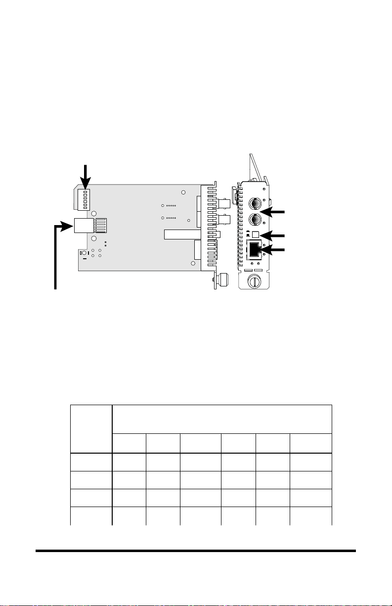
DIP Switches
A set of six DIP switches, located on the back of the line card, allows
you to select from several modes of operation. These switches are
clearly marked on the printed circuit board.
DIP
switches
Power Connector
When setting DIP switches,* the UP position is when the lever of the
DIP switch is pushed away from the circuit board. The DOWN position
is when the lever is pushed toward the circuit board.
10/100
x
II
100 FD
PWR
RX
Port 1
LK
TX
MDI-II to MDI-X Switch
RX
LK
Port 2
TX
NOTE: Not all switches are available on every model. Unmarked
switches are reserved and should be left in the DOWN position. See the
table below for switch locations on the four board types.
noitisoPhctiwSPID
draoB
)thgirottfel(
epyT
12 3 4 5 6
XT-XT1DF1NA1M0012DF2NA2M001
XT-LF1DF1RLLFCLL2DF2NA2M001
XF-LF1DF1RLLFCLL2DF2RLL —
XF-XT1DF1NA1M0012DF2RLLFCLL
*DIP switches also can be managed via console commands or with Metrobility’s NetBeacon™ or WebBeacon™
management software. Refer to the
Software Installation & User’s Guide
management information.
Command Line Interface Reference Guide, NetBeacon Element Management
or
WebBeacon Management Software Installation & User’s Guide
for software
Radiance 10/100Mbps Interface Line Cards 7

Auto-Negotiation Switch (AN)
Switches AN1 and AN2 control the use of auto-negotiation on their
respective copper ports. To enable auto-negotiation, push the lever UP.
To disable this function, push the lever DOWN. The default setting is
auto-negotiation enabled.
When a port has auto-negotiation enabled, it advertises 10/100Mbps and
full/half duplex capabilities when both its speed (100M) and duplex
(FD) switches are also enabled. These are the default settings on a
copper port. If the 100M switch is disabled, the port advertises only
10Mbps capability. If the FD switch is disabled, the port advertises only
half duplex.
When auto-negotiation is disabled, the port’s duplex is determined by
its FD switch setting and its speed is set by its 100M switch.
*
10/100Mbps Switch (100M)
*
Switches 100M1 and 100M2 control the speed setting for their respective copper ports. The speed setting determines which speed is advertised when auto-negotiation is enabled. If auto-negotiation is disabled,
the port speed is the same as the switch setting, where UP is 100Mbps
and DOWN is 10Mbps.
When the 100M switch is UP, the port advertises 10/100Mbps capability if auto-negotiation is enabled. This is the default setting. If autonegotiation is disabled, the port’s speed is set to 100Mbps.
When the 100M switch is DOWN, the port advertises only 10Mbps
capability if auto-negotiation is enabled. If auto-negotiation is disabled,
the port’s speed is set to 10Mbps.
Half/Full Duplex Switch (FD)
*
For copper ports with auto-negotiation disabled and all fiber optic ports,
switches FD1 and FD2 determine the duplex mode of their respective
ports. A port operates at full duplex when its FD switch is UP. It
operates at half duplex when its FD switch is DOWN. The default is
full duplex enabled (UP).
With auto-negotiation enabled on a copper port, the port advertises full/
half duplex capability when its FD switch is UP. The port advertises
only half duplex when its FD switch is DOWN.
*
Changes to the AN, 100M and FD switch settings only come into effect after the power-cycle
initialization.
8 Installation Guide
 Loading...