

Page 1
COMMAND LINE INTERFACE
MGT-10
T
P
C
O
N
S
O
L
E
LK
AT
PWR
A
B
R
ER
MGT-10
1
2
C
O
N
S
O
L
E
PWR
ER
Reference Guide
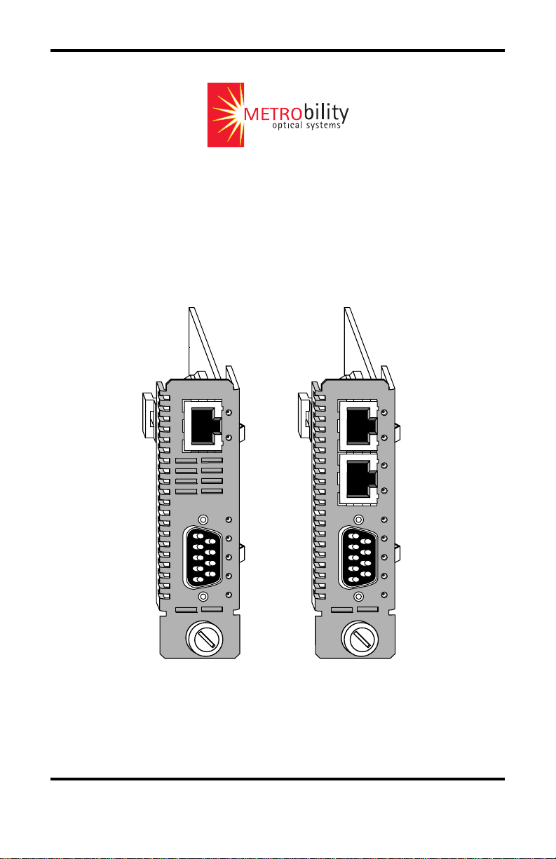
Models: 7501-M / R501-M / R502-M
LK
AT
LK
AT
A
B
R
Page 2

This publication is protected by the copyright laws of the United States and other countries, with all rights
reserved. No part of this publication may be reproduced, stored in a retrieval system, translated,
transcribed, or transmitted, in any form, or by any means manual, electric, electronic, electromagnetic,
mechanical, chemical, optical or otherwise, without prior explicit written permission of Metrobility Optical
Systems, Inc.
Lancast, the Lancast logo, and “the twister” are registered trademarks; Metrobility Optical Systems, the
Metrobility Optical Systems logo, “twister”, “redundant twister”, AutoTwister, MicroChassis, NetBeacon,
and WebBeacon are trademarks of Metrobility Optical Systems, Inc. All other trademarks are the
property of their respective owners.
“redundant twister” technology is a patent of Metrobility Optical Systems, Inc.
The information contained in this document is assumed to be correct and current. The manufacturer is
not responsible for errors or omissions and reserves the right to change specifications at any time
without notice.
© 1999-2003 Metrobility Optical Systems, Inc. All rights reserved. Printed in USA.
Page 3

Table of Contents
Command Line Interface Reference Guide
Introduction .............................................................................................................. 9
Notation Conventions ......................................................................................... 9
Product Overview ............................................................................................. 10
Installation Guide ................................................................................................... 11
Install the Management Line Card.................................................................... 11
Connect to the Network .................................................................................... 12
Connect to the Stack ......................................................................................... 12
Boot Up for SNMP Management...................................................................... 13
Power-on Boot Indications ........................................................................ 13
Management Line Card LED Indicators ................................................... 13
Configuration of the Boot Loader ............................................................. 15
Manual Configuration ............................................................................... 16
Stack Configuration ........................................................................... 17
Boot Completion Indications .................................................................... 20
Login Instructions ..................................................................................... 21
CLI Access via Modem.....................................................................................22
Persistence Data ................................................................................................ 24
Upgrade Procedures .......................................................................................... 25
Upgrade Firmware Via FTP ...................................................................... 25
Firmware Boot Process via TFTP ............................................................. 26
Upgrading from a TFTP Server ......................................................... 27
Upgrading from Disk ......................................................................... 27
NetBeacon Management Software ............................................................ 27
Obtaining Metrobility MIB and Firmware Files............................................... 28
Console Commands ................................................................................................ 29
Guest/Admin/Root Privilege Overview ............................................................ 29
Guest Privilege Commands .............................................................................. 30
Utility Commands ..................................................................................... 30
Command: cd ..................................................................................... 30
Command: chassis ............................................................................. 30
Command: clrscr................................................................................ 30
Command: exit................................................................................... 30
Command: help.................................................................................. 31
Command: history ............................................................................. 31
Command: ls ...................................................................................... 32
Command: module............................................................................. 32
Command: ping ................................................................................. 33
Command: port .................................................................................. 33
Command: pwd.................................................................................. 33
Page 4

Command: pwv.................................................................................. 33
Command: quit .................................................................................. 34
Command: remote ............................................................................. 34
Command: remoteport ....................................................................... 34
Command: top ................................................................................... 34
Command: up..................................................................................... 35
Show Commands....................................................................................... 35
Command: show acl .......................................................................... 35
Command: show arp .......................................................................... 35
Command: show chassis .................................................................... 36
Command: show help ........................................................................ 37
Command: show interface ................................................................. 37
Command: show ip help .................................................................... 38
Command: show ip routes ................................................................. 38
Command: show ip stats .................................................................... 38
Command: show log all ..................................................................... 39
Command: show log details............................................................... 40
Command: show log help .................................................................. 41
Command: show log severities .......................................................... 41
Command: show log summary .......................................................... 42
Command: show log tail .................................................................... 42
Command: show mac ........................................................................ 42
Command: show module ................................................................... 43
Command: show motd ....................................................................... 44
Command: show netstat active .......................................................... 44
Command: show netstat all................................................................ 45
Command: show netstat help ............................................................. 47
Command: show netstat interface...................................................... 48
Command: show netstat routes .......................................................... 48
Command: show netstat snmp ........................................................... 48
Command: show netstat statistics ...................................................... 49
Command: show port......................................................................... 51
Command: show stats rmon............................................................... 53
Command: show system .................................................................... 53
Command: show time ........................................................................ 54
Command: show trap controls ........................................................... 54
Command: show trap destination ...................................................... 55
Command: show trap help ................................................................. 55
Admin Privilege Commands............................................................................. 55
Bootp Commands ...................................................................................... 55
Command: bootp -all ......................................................................... 55
Command: bootp -delete.................................................................... 56
Command: bootp -help ...................................................................... 56
Command: bootp -set......................................................................... 56
4 Table of Contents
Page 5

Clear Commands ....................................................................................... 57
Command: clear acl ........................................................................... 57
Command: clear arp........................................................................... 57
Command: clear help ......................................................................... 57
Command: clear ip help ..................................................................... 58
Command: clear ip route ................................................................... 58
Command: clear log........................................................................... 58
Command: clear motd........................................................................ 58
Command: clear snmp community .................................................... 59
Command: clear snmp help ............................................................... 59
Command: clear trap destination ....................................................... 59
Command: clear trap help.................................................................. 60
Reset Commands ....................................................................................... 60
Command: reset chassis..................................................................... 60
Command: reset help ......................................................................... 60
Command: reset module .................................................................... 60
Command: reset remote ..................................................................... 61
Set Commands........................................................................................... 61
Command: set acl .............................................................................. 61
Command: set arp .............................................................................. 61
Command: set chassis asset ............................................................... 61
Command: set chassis help ................................................................ 62
Command: set chassis name .............................................................. 62
Command: set community ................................................................. 62
Command: set help ............................................................................ 63
Command: set ip address ................................................................... 63
Command: set ip help ........................................................................ 64
Command: set ip route....................................................................... 64
Command: set logging add ................................................................ 64
Command: set logging all .................................................................. 65
Command: set logging delete ............................................................ 65
Command: set logging help ............................................................... 66
Command: set logging none .............................................................. 66
Command: set module asset .............................................................. 66
Command: set module autorecover ................................................... 66
Command: set module autorevert ...................................................... 67
Command: set module backpressure ................................................. 67
Command: set module bootpdisable.................................................. 67
Command: set module bootpenable................................................... 68
Command: set module disable........................................................... 68
Command: set module enable............................................................ 68
Command: set module fdflowctrl ...................................................... 68
Command: set module ftpdisable ...................................................... 69
Command: set module ftpenable ....................................................... 69
Command: set module help ............................................................... 69
Command Line Interface 5
Page 6

Command: set module image ............................................................ 70
Command: set module llcf ................................................................. 72
Command: set module name ............................................................. 72
Command: set module redabsel ......................................................... 72
Command: set module redlink........................................................... 73
Command: set module redloa ............................................................ 73
Command: set module redmode ........................................................ 73
Command: set module redtx .............................................................. 74
Command: set module sduplexAll..................................................... 74
Command: set module sfdflowctrlAll ............................................... 74
Command: set module shdflowctrlAll............................................... 75
Command: set module SONAR......................................................... 75
Command: set module telnetdisable .................................................. 75
Command: set module telnetenable ................................................... 76
Command: set module webdisable .................................................... 76
Command: set module webenable ..................................................... 76
Command: set module webredirect ................................................... 76
Command: set module webselect ...................................................... 77
Command: set module write .............................................................. 77
Command: set motd ........................................................................... 77
Command: set port autoneg ............................................................... 78
Command: set port bandwidth........................................................... 78
Command: set port bert ..................................................................... 79
Command: set port burstlength.......................................................... 79
Command: set port disable ................................................................ 79
Command: set port dislbkres ............................................................. 80
Command: set port duplex ................................................................. 80
Command: set port enable ................................................................. 80
Command: set port fault .................................................................... 81
Command: set port fefenable ............................................................. 81
Command: set port help..................................................................... 81
Command: set port linebuildout ........................................................ 82
Command: set port linecode .............................................................. 83
Command: set port llr ........................................................................ 83
Command: set port loopback ............................................................. 83
Command: set port name ................................................................... 84
Command: set port remotelpbk ......................................................... 84
Command: set port speed................................................................... 85
Command: set prompt........................................................................ 85
Command: set snmp community ....................................................... 85
Command: set snmp help................................................................... 86
Command: set system contact ........................................................... 86
Command: set system help ................................................................ 86
Command: set system location .......................................................... 86
Command: set system name .............................................................. 87
6 Table of Contents
Page 7

Command: set time ............................................................................ 87
Command: set trap control................................................................. 87
Command: set trap destination .......................................................... 87
Command: set trap help ..................................................................... 88
Show Command ....................................................................................... 89
Command: show communities .......................................................... 89
Command: show snmp community ................................................... 89
Command: show snmp help............................................................... 89
User Commands ....................................................................................... 89
Command: user -all............................................................................ 89
Command: user -delete ...................................................................... 90
Command: user -help......................................................................... 90
Command: user -set ........................................................................... 90
Utility Commands ..................................................................................... 90
Command: cat .................................................................................... 90
Command: copyboot.......................................................................... 91
Command: echo ................................................................................. 92
Command: ftp .................................................................................... 92
Command: head ................................................................................. 93
Command: nvclear............................................................................. 93
Command: password ......................................................................... 94
Command: tail ................................................................................... 94
Command: telnet................................................................................ 95
Command: tftp ................................................................................... 95
Command: touch................................................................................ 96
Root Privilege Commands ................................................................................ 96
Command: clear snmp user ............................................................... 97
Command: cp..................................................................................... 97
Command: delhost ............................................................................. 97
Command: getaddr............................................................................. 98
Command: gethname ......................................................................... 98
Command: ifconf ............................................................................... 98
Command: mkdir ............................................................................... 98
Command: mount .............................................................................. 99
Command: mv ................................................................................... 99
Command: rm .................................................................................. 100
Command: rmdir.............................................................................. 100
Command: set snmp user................................................................. 100
Command: setenv ............................................................................ 101
Command: sethost ........................................................................... 101
Command: show snmp engineID..................................................... 101
Command: show snmp user ............................................................. 102
Command: sync ............................................................................... 102
Command: umount .......................................................................... 102
Command Line Interface 7
Page 8

Discontinued Product Suppport ...................................................................... 103
Managed Fixed Port Chassis ................................................................... 103
Persistence for a Fixed Port Chassis ....................................................... 104
Product Safety and Compliance Statements ................................................... 105
Warranty and Servicing................................................................................... 106
8 Table of Contents
Page 9

Introduction
This two-part document contains installation procedures and console
commands necessary for the operation of the Metrobility 7501-M, R501-M, and
R502-M management cards. The first section describes how to connect the card
to the network and to boot up for SNMP management. The second section
describes the commands available to three privilege classes of users:
• Guest
• Admin
• Root
Guest users can view information about the system, but cannot modify any of
the fields. Admin users can monitor and configure the system, including its
modules and ports. Root users, under the direction of a Metrobility support
engineer, can customize or recover the system and internal file system.
The three user privileges correspond to a login and password of the same name.
This list is cumulative (i.e., Admin privileges include Guest privileges, and Root
privileges include all commands).
The Console Commands section is organized by the three privilege groups. The
commands are listed by type (set, show, etc.). Use the comprehensive Table of
Contents to locate documentation for a particular command.
Notation Conventions
This section describes the conventions used in this document.
Font Conventions
Times Times is the default font used for general text.
Arial Arial is used for program examples, prompt responses, and other
system output.
Symbol Conventions
The following symbol conventions are used in this manual.
< > Angle brackets indicate that the enclosed information is a required
entry.
[ ] Square brackets indicate that the enclosed information is optional.
| A vertical bar separating two text items indicates that either term may
be entered as a value.
Command Field Conventions
<chassis> Chassis number in the stack.
Command Line Interface 9
Page 10

<module> Chassis slot number where the line card is installed.
[-converter] Media converter number on a fixed port chassis.
<port> Port number on the line card.
<remote> Remote card number connected to an access line card.
<remoteport> Port number on a remote card connected to an access line card.
Product Overview
The management card is the SNMP agent for the chassis. Embedded in the card
is the WebBeacon™ software for Web-based management of your devices. Used
in conjunction with Metrobility’s NetBeacon™ or WebBeacon management
software, or any SNMP application, the card delivers individual board status
directly to the network administrator. Follow the console commands documented in this guide to configure the cards in the chassis.
7501-M and R501-M Ethernet Management Modules
The x501-M Ethernet management module provides a single 10Base-T interface
for remote SNMP management. The module includes a 33MHz processor and
offers 8Mbytes of memory. Connected through the backplane to other modules
in the chassis, the x501-M uses the management software to access and report
statistical information. Thus, the network administrator receives information on
network operations via a PC instead of having to make multiple trips to the
wiring closet. In a stacked chassis configuration, the x501-M is used in the slave
chassis that is connected to a master chassis.
R502-M Dual-Port Ethernet Management Card
Developed for the Radiance Optical Ethernet System, the R502-M supports all
Metrobility chassis and both access line cards and interface line cards. The
R502-M offers a 50MHz processor and 32Mbytes memory and is required for
the NetBeacon database plug-in. Each Ethernet interface has a unique IP address
and subnet mask, and the management software can access all MIB data through
either interface. The second interface can be connected to a stack of up to seven
chassis using the Metrobility chassis stacking line card or an external hub. In a
stacked chassis configuration, the R502-M must be used as the master
management card. R502-Ms may also be used in the slave chassis in the stack.
10 Introduction
Page 11
Installation Guide
This section describes how to install the management line card into the
chassis, connect to the network and stack, and boot up for SNMP management.
NOTE: Electrostatic discharge precautions should be taken when handling any
line card. Proper grounding is recommended (i.e., wear a wrist strap).
Install the Management Line Card
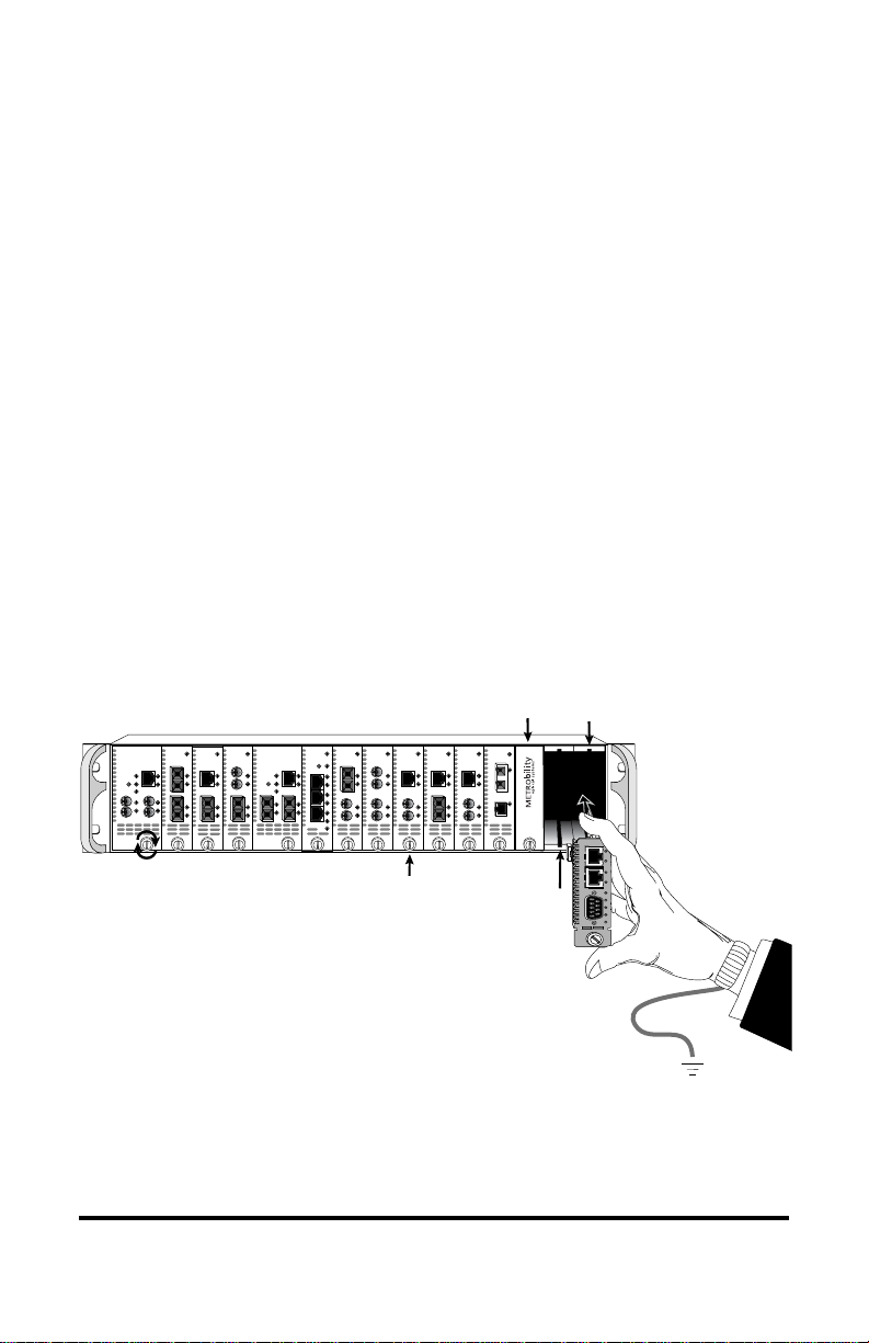
The management card must be installed in the slot furthest to the right of the
chassis. You may install it in either slot of a two-slot chassis. All other line cards
may be installed into any slot.
Follow the simple steps below to install the management card:
• Grasp the card by the front panel as shown.
• Line the edges of the card with the slot guides and slide the card in until
the edges are flush and even with the front of the unit. Do not force the
card into the slot unnecessarily. It should slide in easily and evenly.
• Secure by turning the thumb screw clockwise until snug. The card is now
ready for connection to the network.
Management
100 BASE
100 BASE
“
redundant twister
MAIN
R
PWR
LK
X
M
M
SW
AT
RESET
T
X
PRIMARY
SECONDARY
R
LK
LK
R
R
X
X
X
S
AT
AT
M
T
T
X
X
T
X
IMPORTANT!
Tighten thumb screw
to secure each card firmly
to platform before making
network connections.
Blank Panel
100 BASE
100 BASE
100 BASE
100 BASE
10 BASE
PWR
PWR
PWR
redundant twister
TP
R
LK
LK
X
LK
M
M
AT
AT
AT
T
RESET
X
SECONDARY
FL
R
R
X
R
LK
LK
LK
X
X
S
M
AT
AT
AT
T
T
T
X
X
X
100 BASE
“
PWR
SW
RESET
MAIN
PWR
LK
LK
M
A
SW
AT
AT
I
N
LK
PRIMARY
P
R
AT
LK
LK
I
R
X
AT
AT
LK
S
T
E
X
C
AT
SEC
10 BASE
PWR
PWR
PWR
TP
R
R
X
LK
LK
LK
X
M
M
M
M
T
X
R
X
S
M
T
X
AT
AT
AT
T
X
FL
R
R
LK
LK
LK
X
X
S
M
AT
AT
AT
T
T
X
X
Thumb Screw
1000BASE
100 BASE
100 BASE
R
X
T
X
PWR
PWR
PWR
SX
LK
R
TX
TX
X
LK
LK
M
M
AT
AT
T
X
FX
FX
LX
LK
R
LK
LK
X
S
M
AT
AT
T
X
Card Guide
Card
OC-12
MGT-10
PWR
LK
T
P
RXLK
LK
AT
M
M
M
M
T
X
PWR
LK
LK
R
A
C
X
O
S
S
M
B
N
M
S
T
O
R
X
L
E
ER
MGT-10
LK
1
AT
LK
2
AT
PWR
A
C
O
N
B
S
O
L
R
E
ER
CAUTION: Danger of explosion if the battery on the management card is incorrectly
replaced. Replace only with the same or equivalent type recommended by
the manufacturer. Dispose of used batteries according to the manufacturer’s
instructions.
Command Line Interface 11
Page 12

Connect to the Network
Management Card Connections
The management card supports 10Base-T Ethernet.
• Using a standard Category 3 or 5 UTP cable, connect the management
card to your network. If you are installing an R502-M, connect Port 1 to
your network. Although the port can be configured for either full or half
duplex, half duplex is recommended. Refer to the Console Commands
section for a detailed description of configuration commands.
• Using the supplied null-modem console cable, connect the male DB-9
port on the management card to the serial port on your PC.
Connect to the Stack
R502-M Management Card Only
The R502-M management card supports two 10Base-T Ethernet connections.
When connecting to your network, use a standard Category 3, 4 or 5 UTP cable.
Master Chassis
• Connect port 1 of the master R502-M to your network. For proper
operation, the port is preset to half duplex and should not be changed.
• Connect port 2 of the master R502-M to a Metrobility chassis stacking
line card or to a hub or switch that is NOT on your network. Port 2 is
preset to half duplex and should not be changed.
• Using the supplied null-modem console cable, connect the male DB-9
port on the master R502-M to the serial port on your PC.
Slave Chassis
• For each slave chassis you want to include in the stack, connect the
Ethernet port on its management card to the same chassis stacking card,
hub, or switch to which you connected the master R502-M. This provides
the communication path between the master R502-M and the network
stack.
When using an R502-M in the slave position, use Port 1 to make the
Ethernet connection to the stack, and disable Port 2 via the boot configuration menu. (See page 17.)
12 Introduction
Page 13
Boot Up for SNMP Management
Management of the Metrobility chassis can be provided through our NetBeacon
or WebBeacon software, or any SNMP network management application, via a
PC. SNMP is supported on many general network platforms: SunNet Manager,
HP OpenView for UNIX, HP OpenView for NT, SNMPc and others. Refer to the
Console Commands section for a detailed description of configuration commands.
The PC Terminal Session Parameters are as follows:
• 9600 Baud / 8 data bits / 1 stop bit / no parity / no flow control
Power-on Boot Indications
Following power-up, the boot image is automatically executed. It starts by
performing a system initialization, followed by diagnostic tests. During this
process, the Run LED is off and the Error LED blinks. After diagnostics are
complete, if a failure has occurred, the Error LED remains on. The Run LED
does not illuminate until the operating system is successfully started.
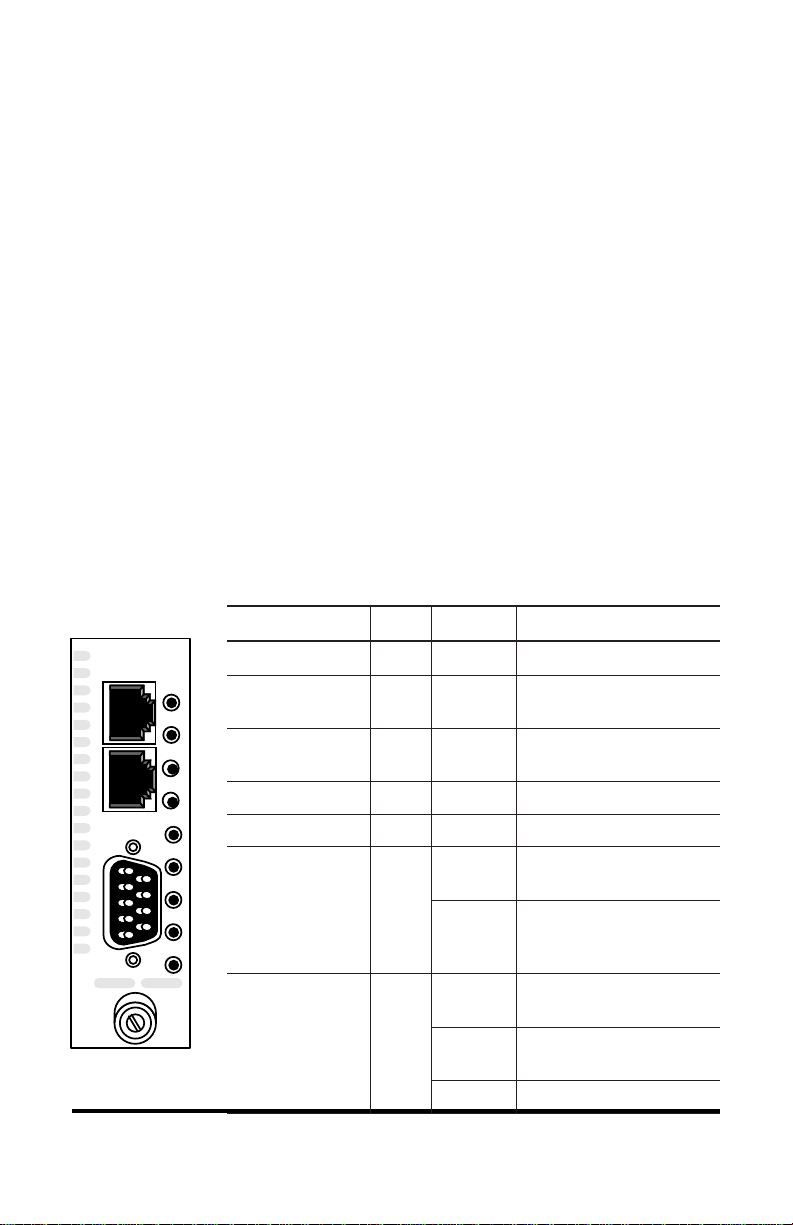
Management Line Card LED Indicators
emaNDELlebaLsutatSnoitacidnI
MGT-10
1
2
C
O
N
S
O
L
E
PWR
LK
AT
LK
AT
A
B
R
ER
nuRR
kniLtenrehtEKLNOtneserpKNIL
TCAtenrehtETANO
rewoPRWPNO
AylppuSrewoPANONOsiAylppusrewoP
BylppuSrewoPBNONOsiBylppusrewoP
rorrERE
FFO
NO
NO
)ydaets(
NO
)gniknilb(
FFOnoitarepolamroN
dnatneserpKNIL
tekcapgniviecer
sidraceniltnemeganaM
rewopgniviecer
scitsongaidgnimrofreP
SOgnidaolro
dnadaolSOlufsseccuS
gnitarepometsys
yllamron
toobrocitsongaiD
eruliaf
scitsongaidgnimrofreP
metsysgnizilaitniro
Command Line Interface 13
Page 14

The following is an example of the console display information:
Metrobility Optical Systems Inc. Boot Application : 3.4.0
Executing Power-On Selftest.....
———————————————————————————————
NETWORK INTERFACE PARAMETERS:
LAN IP address will be obtained from BOOTP
HARDWARE PARAMETERS:
Serial channels will use a baud rate of 9600
HARDWARE PARAMETERS:
R502-M Mpc850 (Rev 0.1) CPU running at 50 Mhz with 10 Mhz input clock
DRAM 32 Mbytes
NVRAM 8 Kbytes
FLASH 8 Mbytes
This board’s Primary Ethernet MAC address is 0:0:0:0:0:0
The Primary Ethernet port will run in Half duplex mode
The board’s Secondary Ethernet MAC address is 0:0:0:0:0:0
The Secondary Ethernet port will run in Half duplex mode
M7500 BOOTLOADER PARAMETERS:
Chassis is not in a Stack
Name of the Boot image is boot.bin
Boot via the DISK Bootloader
Disk device type is FLASH
ID of the disk to be used is 0
Volume is pHILE formatted
The file to load and start is corepm.biz
After board is reset, start-up code will wait 10 seconds
———————————————————————————————
To change any of this, press any key within 10 seconds
(M)odify any of this or (C)ontinue? [M] c
Verifying volume.
If you don’t have a BOOTP server, or if you don’t have a BOOTP entry for this
system, you will see the following message:
BOOTP request failed: Check for a RARP server/Network Error
If you wish to set up your BOOTP server, you must provide an IP address,
subnet mask, and default gateway. If you do not wish to use BOOTP, you can hit
any key and modify the boot parameters.
14 Installation Guide
Page 15

Configuration of the Boot Loader
The boot loader can be configured to obtain its image and configuration information from three different sources: manually through the boot loader configuration dialog, through a BOOTP server, or partially configured through a RARP
server.
To configure the boot load type, press any key within the designated time to
access the system configuration menus.
noitpOtooBnoitpircseD
:gifnoClaunaM
metsySeliF
.selcycrewop
PTOOBmetsystegotkrowtenruoynirevresPTOOBastcatnoC
.toobotdesunoitamrofni
:gifnoClaunaM
tooBPTFT
.selcycrewop
neht,noitamrofninoitarugifnocmetsystupniotresuehtseriuqeR
gnisumetsyselifdraob-noehtmorfmetsysgnitarepoehtstrats
hguorhtdevassinoitamrofninoitarugifnocmetsyS.noitamrofnitaht
neht,noitamrofninoitarugifnocmetsystupniotresuehtseriuqeR
tahtgnisurevresPTFTamorfmetsysgnitarepoehtstrats
hguorhtdevassinoitamrofninoitarugifnocmetsyS.noitamrofni
The following configuration information is required:
PIemaNderiuqeRnehWnoitpircseD
sserddAPIPTFT,eliF,PTOOBotderiuqersimetsysehtfosserddaPIehT
tenbuSPI
ksaM
epyTtooBPTFT,eliF,PTOOBehtdaollliwmetsysehtfienimretedotdesU
1.0.0.0ot
PTFT,eliF,PTOOBehttratsotderiuqersiksamtenbusPIehT
.metsysgnitarepo
.metsysgnitarepoehttrats
tesebtsumsserddaPIeht,desusiPTOOBfI
0.0.0.0,sserddaPIehttegotdesusiPRARfI
.dleifsserddaPIehtnidecalpebtsum
rometsyseliflacolehtmorfmetsysgnitarepo
.PTFTaivmetsyselifdekrowtenamorf
emaNeliFPTFTresueht,PTFTaivdedaolebotsielifehtfI
tluafeD
yawetaG
krowtenruoynisi
.metsyselifetomerehtnoeman
yawetagtluafedafi
elifdnahtapmetsysgnitarepoehtretnetsum
.yawetagretuortluafedkrowtenruoY
Command Line Interface 15
Page 16

Manual Configuration
The following is an example of the console display information:
Metrobility Optical Systems Inc. Boot Application : 3.4.0
Executing Power-On Selftest......
————————————————————————————
NETWORK INTERFACE PARAMETERS:
LAN IP address will be obtained from BOOTP
HARDWARE PARAMETERS:
Serial channels will use a baud rate of 9600
HARDWARE PARAMETERS:
R502-M Mpc850 (Rev 0.1) CPU running at 50 Mhz with 10 Mhz input clock
DRAM 32 Mbytes
NVRAM 8 Kbytes
FLASH 8 Mbytes
This board’s Primary Ethernet hardware address is 0:0:0:0:0:0
The Primary Ethernet port will run in Half duplex mode
This board’s Secondary Ethernet hardware address is 0:0:0:0:0:0
The Secondary Ethernet port will run in Half duplex mode
M7500 BOOTLOADER PARAMETERS:
Chassis is not in a Stack
Name of the Boot image is boot.bin
Boot via the TFTP Bootloader
IP ADDRESS of the TFTP host RARP server
The file to download and start is corepm.biz
After board is reset, start-up code will wait 10 seconds
————————————————————————————
To change any of this, press any key within 10 seconds
(M)odify any of this or (C)ontinue? [M]
Each question that the boot loader poses has a default response contained within brackets
[ ]. If the system has not been configured, the brackets contain the factory default
values. If the system has been configured, the system saves the last used values.
For each of the following questions, you can press <Return> to select the value shown in
braces, or you can enter a new value.
NETWORK INTERFACE PARAMETERS:
This board's Primary LAN IP address (0.0.0.0 = RARP, 0.0.0.1 = BOOTP)? [0.0.0.1]
Management software requires IP protocols (SNMP and FTP) to work properly.
For this reason, the boot loader prompts you for an IP address. IP addresses can
be manually assigned, or assigned via a RARP or BOOTP server within the
network to which the chassis is connected. If you are configuring an R502-M as
16 Installation Guide
Page 17

the first chassis in a stack, you must do it manually.
To set up the system using BOOTP, enter <0.0.0.1> in the board’s LAN IP
address field. To configure the system using RARP, enter <0.0.0.0> in the
board’s LAN IP address field.
If you are configuring the system manually, the following question is asked. Use
the default, or enter a new subnet mask.
Subnet mask for Primary LAN (0.0.0.0 for none)? [0.0.0.0]
For the R502-M, you are offered the option of enabling or disabling the secondary Ethernet port. If you are configuring a master R502-M for a stack, enter <Y>
to enable the port. If you are configuring a slave R502-M for a stack, you must
enter <N>.
Do you want a Secondary LAN interface? [Y]
If you chose to enable the secondary LAN interface, the same two questions are
repeated for the port.
This board's Secondary LAN IP address (0.0.0.0 = RARP, 0.0.0.1 = BOOTP)? [0.0.0.1]
Subnet mask for Secondary LAN (0.0.0.0 for none)? [0.0.0.0]
Stack Configuration
If you are configuring for a stack, the board’s secondary LAN IP address must
be a valid class B address, according to RFC 1597.
secondary IP address = 172.31. 1.17
network host
• Set the network half of the address between 172.16.0.0 and 172.31.0.0.
• Set the host half of the address to be the chassis’s stack position number
followed by the slot number of its management card.
• All other chassis in the same stack must have an IP address with the same
network portion that was assigned to the R502-M’s secondary interface.
Increment the stack positions by one. Up to seven chassis are supported in
each stack.
Example: 172.16.1.17 stack position 1, slot 17 (17-slot chassis)
172.16.2.12 stack position 2, slot 12 (12-slot chassis)
172.16.3.1 stack position 3, slot 1 (2-slot chassis)
Command Line Interface 17
Page 18

• After manually configuring the first chassis in the stack, an alternative
method of adding other chassis is to use the administrative level command:
bootp -set. Refer to the Console Commands section for further details.
The following questions pertain to the board’s primary interface.
Should there be a default gateway for packet routing? [Y]
What is its IP address? [0.0.0.0]
The boot loader poses the following questions for hardware parameters:
HARDWARE PARAMETERS:
Baud rate for serial channels [9600]
HARDWARE PARAMETERS:
Do you want to change the board's Primary Ethernet MAC address? [N]
Do you want to change the board’s Secondary Ethernet MAC address? [N]
The following questions relate to stacking and load type.
NOTE: • The x501-M management module does not support stacking.
• The maximum number of chassis supported in a stack is seven (7).
M7500 BOOTLOADER PARAMETERS:
Is this Chassis in a Stack? [Y]
Stack Position (1-7)? [1]
Boot from (D)isk or via (T)ftp over the network? [D]
Transfer file to disk via TFTP? [N]
Name of the file to load and start? [corepm.biz]
How long (in seconds) should CPU delay before starting up? [10]
The boot loader allows the operating system to be loaded from either the onboard file system or from a network accessible file system via TFTP. The onboard file system is the default method of image load.
If you select to load via TFTP, the boot loader poses these remaining questions:
Transfer file to disk via TFTP? [N] y
IP address of the server to copy file from? [0.0.0.0] 100.132.65.23
Name of the file to transfer? [corepm.biz]
Volume needs formatting? [N]
How long (in seconds) should CPU delay before starting up? [10]
NOTE: This method of operating system load is primarily for loading a new
operating system version, without deleting the old version from the system.
18 Installation Guide
Page 19

Once the configuration is complete, the boot loader displays your responses in
the start-up mode console description. You can either continue with the boot
process or change any configuration parameters.
NETWORK INTERFACE PARAMETERS:
IP address on Primary LAN is 100.132.60.155
Primary LAN interface’s subnet mask is 255.255.255.0
IP address on Secondary LAN is 100.168.0.1
Secondary LAN interface’s subnet mask is 255.255.255.0
IP address of default gateway to other networks is 100.132.60.1
HARDWARE PARAMETERS:
Serial channels will use a baud rate of 9600
HARDWARE PARAMETERS:
R502-M Mpc850 (Rev 0.1) CPU running at 50 Mhz with 10 Mhz input clock
DRAM 32 Mbytes
NVRAM 8 Kbytes
FLASH 8 Mbytes
This board’s Primary Ethernet MAC address is 0:10:9f:14:C:12
The Primary Ethernet port will run in Half duplex mode
This board’s Secondary Ethernet MAC address is 0:10:9f:14:C:13
The Secondary Ethernet port will run in Half duplex mode
M7500 BOOTLOADER PARAMETERS:
Stack Position is 1
Name of the Boot image is boot.bin
Boot via the DISK Bootloader
Disk device type is FLASH
ID of the disk to be used is 0
Volume is pHILE formatted
The file to download and start is corepm.biz
After board is reset, start-up code will wait 10 seconds
————————————————————————————
(M)odify any of this or (C)ontinue? [M] c
If you are satisfied with the configuration parameters, type <c> to continue with
the boot process. The boot process automatically continues if no key is pressed
within 10 seconds.
Verifying volume.
FLASH driver initialized...
Starting disk download of 44.0.0/corepm.biz...
Decompressing ... One moment...
Each . equals 10K bytes processed (uncompressed)
..........
..........
..........
Command Line Interface 19
Page 20

..........
..........
..........
..........
..........
..........
..........
.....
Decompression Complete!
Disk load completed
Transferring control to the downloaded code
Boot Completion Indications
The operating system displays a number of log messages on the screen as it comes
up. The following is an example of that output:
ROOT :00000000:INFO (DEV_PSEUDO initialized)
ROOT :00000000:INFO (DEV_TFTP initialized)
ROOT :00000000:INFO (DEV_TIMER initialized)
ROOT :00000000:INFO (DEV_TFTP initialized)
ROOT :00000000:INFO (DEV_FLASH initialized)
ROOT :00000000:INFO (DEV_TOD initialized)
ROOT :00000000:INFO (DEV_HTTP initialized)
ROOT :00000000:INFO (DEV_I2C initialized)
ROOT :00000000:INFO (DEV_LED initialized)
ROOT :00000000:INFO (DEV_PHYSICAL initialized)
ROOT :00000000:INFO (Locking boot sectors)
ROOT :00000000:INFO (Image WebBeacon_corepm built on May 12 2003 at 11:09:48 by
bldmstr@ROCKME)
ROOT :00000000:INFO (Revision: 3.4.0)
ROOT :00000000:INFO (Flash File System mounted on device 44.0)
ROOT :00000000:INFO (Telnet daemon initialized)
ROOT :00000000:INFO (TELNET daemon enabled)
ROOT :00000000:INFO (Ftp daemon initialized)
ROOT :00000000:INFO (FTP daemon enabled)
ROOT :00000000:INFO (Dnsd daemon initialized)
ROOT :00000000:INFO (Httpd daemon initialized)
CMGR :00000000:INFO (R131-13 Inserted in IoSlot1_1)
CMGR :00000000:INFO (R502-M Inserted in IoSlot1_2)
CMGR :00000000:INFO (AC Power Supply Inserted in PS Slot A)
CMGR :00000000:INFO (AC Power Supply Inserted in PS Slot B)
20 Installation Guide
Page 21

+******************************************************************************************+
* Metrobility 17 Slot Chassis 19" *
* *
* *
* Fri May 9 19:29:42 2003 *
* Version: 3.4.0 (May 12 2003) *
* Serial Number: A001200048 *
* *
* Copyright 1998 - 2003 Metrobility Optical Systems, Inc. *
+******************************************************************************************+
login:
Login Instructions
To log on to the network, do the following:
•Type your user name at the login prompt and hit <Enter>. The three default
names are guest, admin and root.
•Type your password at the Password prompt and hit <Enter>. The default
passwords are the same as their corresponding user names. Passwords are
not displayed.
To view the current user/password list, delete a user or add a new user, refer to
the ‘user’ commands, which are admin privilege commands.
Example:
login: admin
Password:
sh05 :00000000:INFO (User <Administrator> logged in)
Console>user -all
admin:~N6H1~B:11:11:Administrator:/:psh
guest:~H~Dh‘1:21:21:Guest:/:psh
Console>
Command Line Interface 21
Page 22

CLI Access via Modem
To access the Command Line Interface (CLI) using a modem, the modem must
be configured properly to support remote communications with the console port
on the management card.
To configure your modem, use the AT command set or the software provided by
the modem manufacturer. The settings required to enable a Zoom/Fax Modem
V.34X+ Model 2836 to communicate with a Metrobility management card are
shown in the example below. Please refer to your modem’s manual for compatible A T commands.
Modem Configuration (Zoom/Fax Modem V.34X+ Model 2836 shown)
E0 Disable echo.
N1 Enable automode detection.
Q1 Disable result codes to the DTE (data-terminal equipment).
X0 Disable monitoring of busy tones.
&C0 RLSD (received line signal detector) remains ON at all times.
&D0 Ignore DTR (data terminal ready); must also set &Q5.
&K0 Disable flow control.
&Q5 Modem will try to negotiate an error-corrected link.
&R1 CTS (clear to send) is always ON; RTS (ready to send) is ignored.
&S1 DSR (data set ready) becomes active after answer tone is detected, and
inactive if carrier is lost.
&T5 Disable digital loopback.
&X0 Select internal timing.
S00 Set this to the number of rings for auto-answer; number must be greater
than zero.
Console Port Configuration
The console port on the management card does not use hardware control lines,
nor does it support software flow control. The port is permanently set to the
following configuration:
Speed 9600 baud
Data Bits 8
Parity none
Stop Bits 1
Caution: There is a potential risk of opening a security hole if the modem is
disconnected before logging off from the CLI session.
22 Installation Guide
Page 23

In the following example, a Zoom/Fax Modem V.34X+ Model 2836 is connected to a Windows PC using Hyperterminal with AT commands.
ate1 (turns on echo)
at&vn (displays active and saved configurations)
B1 E0 L1 M0 N1 Q1 T V1 W0 X0 Y0 &C0 &D0 &G0 &J0 &K0 &Q5 &R1 &S1 &T5 &X0 &Y1
S00:001 S01:000 S02:043 S03:013 S04:010 S05:008 S06:002 S07:050 S08:002 S09:006
S10:014 S11:095 S12:050 S18:000 S25:005 S26:001 S36:007 S37:000 S38:020 S44:020
S46:138 S48:007 S95:000
ate0
(turns off echo)
Command Line Interface 23
Page 24

Persistence Data
When a chassis is initially started, the management line card polls all installed
cards and saves their part numbers and hardware switch settings.
When you change a switch setting via software, the card’s part number, hardware switch settings and new software setting are saved.
If you remove the card and insert a new card into its slot, one of the following
occurs:
1) If the part number and hardware switch settings match, the software
switch settings stay the same.
2) If the part number matches but the hardware switch settings do not,
the new hardware switch settings take precedence. All other software
settings remain unchanged.
3) If the part number does not match, all hardware settings for the new
card take precedence and the persistence file is updated with the new
data.
24 Installation Guide
Page 25

Upgrade Procedures
There are several ways of upgrading the embedded code*. This section describes
three methods to upgrade the software.
• Command Line Interface (CLI) via FTP
• BOOT Process (to execute embedded software that does not reside on the
management card, or to transfer embedded software to the management
card via TFTP)
• NetBeacon Management Software
Metrobility does not support storing more than two copies of corepm.biz. If the
Flash File System (FFS) is full, we cannot guarantee operation. In some instances, a full file system can corrupt the FFS. If the file system’s limit is
approached, a warning message will appear on the console asking you to delete
unnecessary files.
Upgrade Firmware Via FTP
To load the image file (corepm.biz) and boot code (boot.bin) via FTP on a local
console, do the following:
1) Copy the corepm.biz and boot.bin files into a directory accessible via FTP.
2) Log on to the console at the administrator or root level.
3) FTP to the system where the corepm.biz and boot.bin files reside.
4) Set the FTP session into binary mode.
5) Go into the directory that contains the corepm.biz and boot.bin files.
Upgrading to a major software release (e.g., from version 2.1 to 3.x) requires
both files to be updated. For most other software upgrades, you may download
only the image file. Upgrading from Release 3.0 to 3.3 requires both files to be
updated.
6) Type “get corepm.biz” and “get boot.bin”.
NOTE: Do NOT reset or power-down the system while upgrading software!
The file system may go into an unknown state causing boot failures.
7) Once the download is complete, quit the FTP session.
* When upgrading software to management cards in a stack, make sure that the same software version is installed
within that stack (e.g., version 3.1 code cannot be mixed with 3.0.1 code in the same stack).
Command Line Interface 25
Page 26

8) If you downloaded the boot code, type “set module image boot <chassis>
<module> file://[path/]boot.bin” (e.g., set module image boot 1 17 file://
boot.bin).
NOTE: Do not to interrupt the process.
9) Reboot the management card by issuing the command: “reset module
<chassis> <module>” (e.g., reset module 1 17).
NOTE: Do NOT use the “reset chassis” command. After successfully
rebooting the management card, you are done. Both boot.bin and
corepm.biz will be running.
Firmware Boot Process via TFTP
Continue with the following steps only AFTER copying boot.bin onto the
management card.
The initial boot process provides two options for upgrading files via TFTP. One
option enables you to execute a file that does not reside on the management
card. This method does not load the file onto the management card. Another
option allows you to transfer the file onto the management card and then execute
it.
1) Copy the corepm.biz file into a directory accessible via TFTP.
2) Reset the management card.
3) During the initial boot process, hit the <space bar>.
4) Select Modify by typing <M>.
5) Make sure the Ethernet port is enabled, and that the network interface and
hardware parameters are set.
Continue with “Upgrading from a TFTP Server” or “Upgrading from Disk.”
26 Installation Guide
Page 27

Upgrading from a TFTP Server
To execute software that resides on a TFTP server, do the following:
A) When asked whether to boot from disk or via TFTP over the network, select
TFTP by typing <T>.
B) Enter the IP address of the TFTP server where corepm.biz is located.
C) Enter the directory and filename for corepm.biz (e.g., \tftpboot\corepm.biz
for Windows or /tftpboot/corepm.biz for Unix).
D) Complete the boot configuration dialog. At the end of the dialog, continue
the boot process by typing <C>. The file will be executed, but not loaded to
disk.
Upgrading from Disk
Continue with the following steps after performing steps 1 through 5 in “Firmware Boot Process Via TFTP.” This section describes how to transfer the
embedded software to the management card via TFTP.
A) When asked whether to boot from disk or via TFTP over the network, select
disk by typing <D>.
B) Type <Y> when prompted with “Transfer file to disk via TFTP?”
C) Enter the IP address of the system where corepm.biz resides.
D) Enter the directory and filename for corepm.biz (e.g., \tftpboot\corepm.biz
for Windows or /tftpboot/corepm.biz for Unix).
E) Complete the boot configuration dialog. At the end of the dialog, continue
the boot process by typing <C>. The file will be loaded to disk and
executed.
NetBeacon Management Software
For detailed instructions on how to download the embedded software and boot
code through NetBeacon, refer to the NetBeacon Element Management Software
Installation & User Guide.
Command Line Interface 27
Page 28

Obtaining Metrobility MIB and Firmware Files
To get the latest Metrobility Management Information Base (MIB)
and firmware files, go to http://www.metrobility.com/support/software.htm.
Follow the on-screen instructions to download the files.
28 Installation Guide
Page 29

Console Commands
Guest/Admin/Root Privilege Overview
Guest Privilege
Login Guest
cd
chassis
clrscr
exit
help
history
ls
module
ping
port
pwd
pwv
quit
remote
remoteport
top
up
show acl
show arp
show chassis
show help
show interface
show ip help
show ip routes
show ip stats
show log all
show log details
show log help
show log severities
show log summary
show log tail
show mac
show module
show motd
show netstat active
show netstat all
show netstat help
show netstat interface
show netstat routes
show netstat snmp
show netstat statistics
show port
show stats rmon
show system
show time
show trap controls
show trap destination
show trap help
Admin Privilege
Login Admin
bootp -all
bootp -delete
bootp -help
bootp -set
clear acl
clear arp
clear help
clear ip help
clear ip route
clear log
clear motd
clear snmp community
clear snmp help
clear trap destination
clear trap help
reset chassis
reset help
reset module
reset remote
set acl
set arp
set chassis asset
set chassis help
set chassis name
set community
set help
set ip address
set ip help
set ip route
set logging add
set logging all
set logging delete
set logging help
set logging none
set module asset
set module autorecover
set module autorevert
set module backpressure
set module bootpdisable
set module bootpenable
set module disable
set module enable
set module fdflowctrl
set module ftpdisable
set module ftpenable
set module help
set module image
set module llcf
set module name
set module redabsel
set module redlink
set module redloa
set module redmode
set module redtx
set module sduplexAll
set module sfdflowctrlAll
set module shdflowctrlAll
set module SONAR
set module telnetdisable
set module telnetenable
set module webdisable
set module webenable
set module webredirect
set module webselect
set module write
set motd
set port autoneg
set port bandwidth
set port bert
set port burstlength
set port disable
set port dislbkres
set port duplex
set port enable
set port fault
set port fefenable
set port help
set port linebuildout
set port linecode
set port llr
set port loopback
set port name
set port remotelpbk
set port speed
set prompt
set snmp community
set snmp help
set system contact
set system help
set system location
set system name
set time
set trap control
set trap destination
set trap help
show communities
show snmp community
show snmp help
user -all
user -delete
user -help
user -set
cat
copyboot
echo
ftp
head
nvclear
password
tail
telnet
touch
tftp
Root Privilege
Login Root
clear snmp user
cp
delhost
getaddr
gethname
ifconf
mkdir
mount
mv
rm
rmdir
set snmp user
setenv
sethost
show snmp engineID
show snmp user
sync
umount
Command Line Interface 29
Page 30

Guest Privilege Commands
Guest commands are basic user commands used to monitor system status. The
default password is: guest
Utility Commands
Command: cd
Description: Change working directory.
Syntax: cd <directory>
Example: Console>cd etc
Command: chassis
Description: Set the chassis scope. The command prompt displays
the selected chassis, and the chassis number is no
longer entered in commands which have a chassis field
(e.g., ‘show module 4’ instead of ‘show module 1 4’).
Syntax: chassis <chassis>
Example: Console>chassis 1
#1>
Command: clrscr
Description: Clear the screen.
Syntax: clrscr
Example: Console>clrscr
Command: exit
Description: Log off.
Syntax: exit
Example: Console>exit
30 Console Commands
Page 31

Command: help
Description: Show available commands.
Syntax: help
Note: Using ‘help’ with another command (e.g., ‘help ping’)
Example: Console>help
Command: history
Description: List all commands that have been entered, or repeat a
Syntax: history, !!, !#
Note: History lists all commands that have been entered.
Example: Console>history
?
will display a description of the command followed by
the following system message <reentrant, not locked>
which may be disregarded.
cd chassis clrscr exit help
history ls module ping port
pwd pwv quit remote remoteport
show top up
prior command.
!! repeats the last command.
!# repeats the #th command in the history list (e.g., !4
repeats the 4th command entered).
1 show mod all
2 pwd
3 ls
4 show time
Console> !!
Date 5/12/2003
Time 18:09:43
Console> !2
44.0.0/
Command Line Interface 31
Page 32

Command: ls
Description: List files.
Syntax: ls [-1FRdfgilqrs] [filename...]
Options: -1 Display output in one column.
Example: Console>ls -l
Command: module
Description: Set the module scope. The command prompt displays
Syntax: module <chassis> <module[-converter]>
Example: Console>module 1 11
-F Put a ‘/’ after each directory name.
-R List files recursively through subdirectories.
-d List actual directory, not contents.
-f Do not sort output.
-g Show group ownership of a file.
-i Print a file’s associated inode.
-l Long output format, show all file details.
-q Show unprintables as ‘?’.
-r Reverse the sort order.
-s Show a file’s size.
total 4
-rwxrwxrwx 1 root 318 May 12 2003 05:50 acl
-rwxrwxrwx 1 root 656 May 12 2003 05:50 hosts
-rwxrwxrwx 1 root 204 May 12 2003 05:50 motd
-rwxrwxrwx 1 root 151 May 12 2003 05:50 passwd
the selected chassis and module. The chassis and
module numbers are no longer entered in commands
which have these fields (e.g., ‘show port 2’ instead of
‘show port 1 11 2’).
#1/11>
32 Console Commands
Page 33

Command: ping
Description: Send ICMP echo request packets to the network
Syntax: ping [-s] <host> [timeout]
Note: When the -s option is specified, ping sends one
Example: Console>ping 100.132.65.99
Command: port
Description: Set the port scope. The command prompt displays the
Syntax: port <chassis> <module[-converter]> <port>
Example: Console>port 1 11 2
host.
datagram per second and prints one line of output for
every response it receives. The default timeout is 10.
ping (100.132.65.99): 56 data bytes
100.132.65.99 is alive
selected chassis, module and port. The chassis, module
and port numbers are no longer entered in commands
which have these fields (e.g., ‘show port’ instead of
‘show port 1 11 2’).
#1/11/2>
Command: pwd
Description: Print working directory.
Syntax: pwd
Example: Console>pwd
Command: pwv
Description: Print working volume.
Syntax: pwv
Example: Console>pwv
44.0.0/
44.0.0
Command Line Interface 33
Page 34

Command: quit
Description: Log off.
Syntax: quit
Example: Console>quit
Command: remote
Description: Set the remote scope. The command prompt displays
Syntax: remote <chassis> <module> <port> <remote>
Example: Console>remote 1 11 2 1
Command: remoteport
Description: Set the remote port scope. The command prompt
Syntax: remoteport <chassis> <module> <port> <remote>
Example: Console>remoteport 1 11 2 1 2
the selected chassis, module, port and remote card.
The chassis, module, port and remote card numbers
are no longer entered in commands which have these
fields (e.g., ‘show module’ instead of ‘show module 1
11 2 1’).
#1/11/2/1>
displays the selected chassis, module, port, remote
card and remote port. The chassis, module, port,
remote card and remote port numbers are no longer
entered in commands which have these fields (e.g.,
‘show port’ instead of ‘show port 1 11 2 1 2’).
<remoteport>
#1/11/2/1/2>
Command: top
Description: Reset the scope so nothing is specified.
Syntax: top
Example: #1/11/2/1/2>top
Console>
34 Console Commands
Page 35

Command: up
Description: Set the scope up one or more levels.
Syntax: up
Note: If no level is specified, the scope will move up one
Example: #1/11/2/1/2>up
Show Commands
Command: show acl
Description: Show entries in the Access Control List (ACL) which
Note: Protocols/services effected: FTP, TELNET,
Syntax: show acl
Example: Console>show acl
up <level>
level.
#1/11/2/1>up 3
#1>
allows a user to limit the end stations (IP addresses)
that communicate with the chassis.
SNMP.
Current ACL entries:
Command: show arp
Description: Show the Address Resolution Protocol table.
Syntax: show arp
Example: Console>show arp
Ip Address Validation Mask
——————— ———————
100.132.065.099 255.255.255.255
100.132.065.023 255.255.255.255
IP Addr Mac addr
—————— —————————
100.132.65.99 0:10:9f:c7:43:20
100.132.65.174 0:10:9f:85:c3:a9
100.132.65.176 0:10:9f:85:ab:6a
Command Line Interface 35
Page 36

Command: show chassis
Description: Show details for a chassis, including its power supply
Syntax: show chassis all
Example #1: Console>show chassis 2
Location : 2
Number of I/O Slots : 17
Number of P/S Slots : 2
Serial Number : B0003900566
Manufacture Date : 12/21/2002
HW Revision : A
Asset ID :
Name : Chassis2
Description : 17 Slot Chassis 19"
Part Number : R5000-17HS
Uptime : 4 days 00:19:47.35
Average Temperature : 111F ( 44C)
Module1_17 (Maximum) : 195F ( 91C)
Module1_14 (Minimum) : 80F ( 27C)
unit(s). If the chassis has multiple cards with temperature
sensors, the cards with the highest and lowest readings
are displayed, along with the average temperature
among all the sensors in the chassis. An access line card
displays the actual temperature of the board, not the air,
and it may be 10 degrees higher than the management
card’s reading. The access line card’s board temperature is functional up to 65°C.
show chassis <chassis>
Power Supply 2 1 : AC PS_A On Power Supply
5 Volt (Millivolts): Current: 5275 Min: 5000 Max: 5500 (IN RANGE)
Power Supply 2 2 : AC PS_B Off Power Supply
5 Volt (Millivolts): Current: 0 Min: 5000 Max: 5500 (OUT OF RANGE)
Example #2: Console>show chassis all
Location I/O Slots P/S Slots Name Description
—————————————————————————————
1172Chassis1 17 Slot Chassis 19"
2172Chassis2 17 Slot Chassis 19"
36 Console Commands
Page 37

Command: show help
Description: Show the ‘show’ commands with a brief description.
Syntax: show help
Example: Console>show ?
Command Description
————————————————
acl : Show Access Control List
arp : Show ARP Tables
chassis : Show chassis information
help : Show this message
interface : Show network interfaces
ip : Show IP; use 'show ip help' for more info
log : Show log; use 'show log help' for more info
mac : Show MAC Information
module : Show module information
motd : Show Message of the Day
netstat : Show netstat; use 'show netstat help' for more info
port : Show port information
stats : Show port statistics
system : Show system information
time : Show time of day
trap : Show Trap Information
show ?
Command: show interface
Description: Show network interfaces.
Syntax: show interface
Example: Console>show interface
IP Interfaces
if# mtu Interface Addr Subnet Mask Broadcast Addr
——————————————————————————————
1 1500 100.132.060.161 255.255.255.000 100.132.060.255
2 1500 100.132.061.161 255.255.255.000 100.132.061.255
3 1536 127.000.000.001 255.000.000.000 127.000.000.000
Command Line Interface 37
Page 38

Command: show ip help
Description: Show ‘show ip’ subcommands.
Syntax: show ip help
Example: Console>show ip help
Command: show ip routes
Description: Show established routes.
Syntax: show ip routes
Example: Console>show ip routes
Destination Gateway Mask Flags Interface
default 100.132.65.1 0.0.0.0 U 1
127.0.0.1 127.0.0.1 0.0.0.0 U 2
100.132.65.0 100.132.65.98 255.255.255.0 U 1
Command: show ip stats
Description: Show MIB II IP statistics.
Syntax: show ip stats
Example: Console>show ip stats
Command Description
—————————————————
help : Show this message
routes : Show IP routes
stats : Show IP statistics
IP Statistics
——————
forwarding 1
defaultttl 64
inreceives 583
inhderrors 0
inaddrerrors 0
forward datagrams 0
unknown protos 0
indiscards 0
indelivers 583
outrequests 633
outdiscards 0
38 Console Commands
Page 39

Command: show log all
Description: Show all available logs.
Syntax: show log all
Example: Console>show log all
Event Logs:
—————
Index :1
Name :'Non-Volatile'
Severities :PROCESSOR FATAL SEVERE ERROR WARNING
Entries :23
Log Size :3984
Free mem :1900
Seq range :1 to 23
outnoroutes 0
reasmtimeout 30
reasmreqds 0
reasmfails 0
fragoks 0
fragfails 0
fragcreates 0
routingdiscards 0
Index :2
Name :'Volatile'
Severities :PROCESSOR FATAL SEVERE ERROR
WARNING INFO PRINT TRAP EVMGR
Entries :86
Log Size :65424
Free mem :58540
Seq range :1 to 86
Index :3
Name :'Trap'
Severities :TRAP
Entries :21
Log Size :8080
Free mem :6256
Seq range :1 to 21
Command Line Interface 39
Page 40

Command: show log details
Description: Show details of desired log records.
Syntax: show log details <log index> [min sequence #] [max
Notes: If no sequence numbers are provided the entire
log will be shown. If no maximum sequence
number is provided the log will be shown to the
end.
Example: Console>show log details 1 15 17
Log: Non-Volatile
————————————————————
Seq Number : 15
Error Number : 7
Error Text : Incorrect Object type
Group Text : pSOS+
Message : test message
Task : psc0
Date : 5/18/2003
Time : 0:03:48
Ticks : 84
Uptime : 23183
Severity : PROCESSOR
————————————————————
Seq Number : 16
Error Number : 8
Error Text : Node’s Object table full
Group Text : pSOS+
Message : test message
Task : psc0
Date : 5/18/2003
Time : 0:03:48
Ticks : 85
Uptime : 23184
Severity : PROCESSOR
————————————————————
Seq Number : 17
Error Number : 9
Error Text : Named Object not found
Group Text : pSOS+
Message : test message
Task : psc0
Date : 5/18/2003
Time : 0:03:48
Ticks : 86
Uptime : 23185
Severity : PROCESSOR
sequence #]
40 Console Commands
Page 41

Command: show log help
Description: Show the ‘show log’ subcommands.
Syntax: show log help
Example: Console>show log help
Command Description
—————————————————
all : Show all logs
details : Show log record details
help : Show this message
severities : Show messages severities
summary : Show log record summary
tail : Show end of log
Command: show log severities
Description: Show the different message severities used for log
messages; also indicate which of them are sent to the
console.
Syntax: show log severities
Note: This command is useful in conjunction with the ‘set
logging’ command.
Example: Console>show log severities
The following message severities are available.
'*' indicates severities that are sent to the console.
FAULT *
FATAL *
SEVERE *
ERROR *
WARNING *
INFO *
PRINT *
DEBUG *
TRAP *
EVENT_MGR *
Command Line Interface 41
Page 42

Command: show log summary
Description: Show a one-line description of log records.
Syntax: show log summary <log index> [min seq #]
[max seq #]
Example: Console>show log summary 2 25 30
Log: Volatile
ROOT :00000000:INFO (Dnsd daemon initialized)
ROOT :00000000:INFO (Httpd daemon initialized)
ROOT :00000000:INFO (HTTP daemon enabled)
CMGR :00000000:INFO (R502-M Inserted in IoSlot1_17)
CMGR :00000000:INFO (R621-11 Inserted in IoSlot1_2)
CMGR :00000000:INFO (R131-15 Inserted in IoSlot1_11)
Command: show log tail
Description: Show a summary of the most recent records in a log.
Syntax: show log tail <log index> [# records]
Note: Defaults to 10.
Example: Console>show log tail 2
Log: Volatile
MAGT:00000000:TRAP (TDM Remote Fault Alarm: Name=Port14_2)
sh01 :00000000:INFO (User <Administrator> logged in)
sh02 :00000000:INFO (User <Guest> logged in)
sh03 :00000000:INFO (User <Administrator> logged in)
sh04 :00000000:INFO (User <Super User> logged in)
sh05 :00000000:INFO (User <Super User> logged in)
sh06 :00000000:INFO (User <Administrator> logged in)
sh07 :00000000:INFO (User <Super User> logged in)
sh08 :00000000:INFO (User <Guest> logged in)
sh09 :00000000:INFO (User <Super User> logged in)
Command: show mac
Description: Show MAC information.
Syntax: show mac
Example: Console>show mac
42 Console Commands
Page 43

Int # IP address Mac
———————————————————
1 100.132.65.248 0:10:9f:18:4:7a
2 100.168.0.1 0:10:9f:18:4:7b
3 127.0.0.1 0:0:0:0:0:0
Command: show module
Description: Show module information.
Syntax: show module all [chassis]
show module <chassis> <module[-converter]>
show module <chassis> <module> <port> <remote>
Note: Specifying an individual module shows all its details.
Example #1: Console>show module all
Location State Type Name Desc #ports
—————————————————————————————————————————
1/3 Enabled Single Module1_3 10M TP to BNC 2
1/4 Enabled Access Module1_4 100M TX to FX SM/SC S/IP 2
1/4/2/1 Enabled Access Module1_4_2_1 100M TX to FX SM/SC S/IP 2
1/5 Enabled Access Module1_5 100M TX to FX SM/SC S/IP 2
1/7 Enabled Access Module1_7 100M TX to FX SM/SC S/IP 2
1/8 Enabled Access Module1_8 100M TX to FX SM/SC S/IP 2
1/10 Enabled Single Module1_10 10M TP to FL MM/ST 2
1/11 Enabled Single Module1_11 10M TP to FL/MM/ST 2
1/16 Enabled Gigabit Module1_16 1000M TX to LX SM/SC 2
1/17 Enabled Management Module1_17 10M Dual TP Management 3
2/2 Enabled Management Module2_2 10M TP Management 2
Example #2: Display details for a Gigabit line card.
Console>show module 1 16
Location : 1/16
Name : Module1_16
Type : Gigabit
Asset ID :
Description : 1000M TX to LX SM/SC
Hardware Revision : A
Part Number : R152-1D
Serial Number : 20115
Manufacturing Date : 05/07/2003
Module State Oper : Enabled
Command Line Interface 43
Page 44

Diagnostic Status : Good
Number of ports : 2
Number of slots : 1
Uptime : 4 days 00:23:07.15
Link Loss Carry Forward Oper : Disabled
Note: When the administrative and operational settings for a
function do not agree, both settings are displayed. The
administrative and operational settings could differ
because the switch is not applicable in a particular
mode or because the switch was changed but has not
yet taken effect.
Command: show motd
Description: Show the message of the day displayed at login.
Syntax: show motd
Example: Console>show motd
This is the message of the day
Command: show netstat active
Description: Show active socket connections.
Syntax: show netstat active
Example: Console>show netstat active
Proto Local Address Foreign Address (state)
udp 0.0.0.0.161
udp 0.0.0.0.3052
tcp 0.0.0.0.21 0.0.0.0.0 LISTEN
tcp 0.0.0.0.23 0.0.0.0.0 LISTEN
tcp 0.0.0.0.80 0.0.0.0.0 LISTEN
tcp 0.0.0.0.705 0.0.0.0.0 LISTEN
tcp 0.0.0.0.1024 0.0.0.0.0 LISTEN
tcp 100.132.35.163.23 100.132.65.143.2352 ESTABLISHED
tcp 100.132.35.163.1024 100.132.35.163.1038 ESTABLISHED
tcp 100.132.35.163.1038 100.132.35.163.1024 ESTABLISHED
44 Console Commands
Page 45

Command: show netstat all
Description: Show all network status information.
Syntax: show netstat all
Example: Console>show netstat all
Proto Local Address Foreign Address (state)
udp 0.0.0.0.161
udp 0.0.0.0.3052
tcp 0.0.0.0.21 0.0.0.0.0 LISTEN
tcp 0.0.0.0.23 0.0.0.0.0 LISTEN
tcp 0.0.0.0.80 0.0.0.0.0 LISTEN
tcp 0.0.0.0.705 0.0.0.0.0 LISTEN
tcp 0.0.0.0.1024 0.0.0.0.0 LISTEN
tcp 100.132.35.163.23 100.132.65.143.2352 ESTABLISHED
tcp 100.132.35.163.1024 100.132.35.163.1038 ESTABLISHED
tcp 100.132.35.163.1038 100.132.35.163.1024 ESTABLISHED
I/F Mtu Address Ipkts Ierrs Opkts Oerrs Queue
1 1500 100.132.35.163 273148 0 358 0 0
6 1536 127.0.0.1 2198 0 2198 0 0
Destination Gateway Mask Flags Interface
default 100.132.35.1 0.0.0.0 UG 1
127.0.0.1 127.0.0.1 0.0.0.0 U 2
100.132.35.0 100.132.35.163 255.255.255.0 U 1
udp:
657 datagrams delivered to users
36 datagrams received for unknown ports
0 datagrams received with other errors
257 datagrams sent
tcp:
24 segments sent
0 segments retransmitted
0 segments sent with RST flag
26 segments received
0 segments received in error
0 failed TCP connection attempts
0 TCP connections reset
Command Line Interface 45
Page 46

ip:
877 received from interfaces
0 drops due to format errors
0 drops due to invalid addresses
0 IP datagrams forwarded
6 IP datagrams discarded due to unknown protocol
0 input datagrams discarded with no problems
871 datagrams delivered to IP user protocols
468 datagrams supplied by IP user protocols
0 outbound datagrams discarded
0 IP datagrams dropped due to no routes
0 IP fragments needing reassembly
0 IP fragments reassembled
0 IP fragments reassembly failures
0 IP datagrams successfully fragmented
0 IP datagrams fragmentation failures
0 IP fragments created
0 IP routing entities discarded
icmp:
Received Sent
Messages 157 187
Errors 0 0
Destination Unreachable 6 36
Time Exceeded 0 0
Parameter Problems 0 0
Source Quenches 0 0
Redirects 0 0
Echos 151 0
Echo Replies 0 151
Timestamps 0 0
Timestamps Replies 0 0
Address Mask Requests 0 0
Address Mask Replies 0 0
snmp:
In Packets 158
Out Packets 347
In Bad Versions 0
In Bad Comm. Names 0
In Bad Comm Uses 0
46 Console Commands
Page 47

In ASN Parse Errors 0
In Too Bigs 0
In No Such Names 0
In Bad Values 0
In Read Onlys 0
In Gen Errors 0
In Total Req. Vars 289
In Total Set Vars 23
In Get Requests 880
In Get Nexts 232
In Set Requests 20
In Get Responses 0
In Traps 0
Out Too Bigs 0
Out No Such Names 8
Out Bad Values 0
Out Gen Errors 0
Out Get Requests 0
Out Get Nexts 0
Out Set Requests 0
Out Get Responses 157
Out Traps 190
Out Silent Drops 0
Out Proxy Drops 0
Command: show netstat help
Description: Show the ‘show netstat’ subcommands.
Syntax: show netstat help
Example: Console>show netstat help
Command Description
—————————————————
active : Show netstat active
all : Show netstat all
help : Show this message
interface : Show netstat interface
routes : Show netstat routes
snmp : Show netstat snmp
statistics : Show netstat statistics
Command Line Interface 47
Page 48

Command: show netstat interface
Description: Show network interface statistics.
Syntax: show netstat interface
Example: Console>show netstat interface
I/F Mtu Address Ipkts Ierrs Opkts Oerrs Queue
1 1500 100.132.65.153 358 0 271 0 50
2 1500 100.168.0.1 0 0 0 0 50
3 1536 127.0.0.1 190 0 190 0 0
Command: show netstat routes
Description: Show IP routes.
Syntax: show netstat routes
Example: Console>show netstat routes
Destination Gateway Mask Flags Interface
default 100.132.35.1 0.0.0.0 UG 1
127.0.0.1 127.0.0.1 0.0.0.0 U 2
100.132.35.0 100.132.35.163 255.255.255.0 U 1
Command: show netstat snmp
Description: Show SNMP statistics.
Syntax: show netstat snmp
Example: Console>show netstat snmp
snmp:
In Packets 21
Out Packets 245
In Bad Versions 0
In Bad Comm. Names 0
In Bad Comm Uses 0
In ASN Parse Errors 0
In Too Bigs 0
In No Such Names 0
In Bad Values 0
In Read Onlys 0
In Gen Errors 0
In Total Req. Vars 236
48 Console Commands
Page 49

In Total Set Vars 0
In Get Requests 0
In Get Nexts 21
In Set Requests 0
In Get Responses 0
In Traps 0
Out Too Bigs 0
Out No Such Names 8
Out Bad Values 0
Out Gen Errors 0
Out Get Requests 0
Out Get Nexts 0
Out Set Requests 0
Out Get Responses 20
Out Traps 225
Out Silent Drops 0
Out Proxy Drops 0
Command: show netstat statistics
Description: Show network statistics.
Syntax: show netstat statistics
Example: Console>show netstat statistics
udp:
105 220 datagrams delivered to users
2 datagrams received for unknown ports
0 datagrams received with other errors
93 datagrams sent
tcp:
152 segments sent
1 segments retransmitted
0 segments sent with RST flag
474 segments received
0 segments received in error
0 failed TCP connection attempts
14 TCP connections reset
ip:
271 received from interfaces
0 drops due to format errors
294 drops due to invalid addresses
Command Line Interface 49
Page 50

0 IP datagrams forwarded
0 IP datagrams discarded due to unknown protocol
0 input datagrams discarded with no problems
977 datagrams delivered to IP user protocols
528 datagrams supplied by IP user protocols
0 outbound datagrams discarded
0 IP datagrams dropped due to no routes
0 IP fragments needing reassembly
0 IP fragments reassembled
0 IP fragments reassembly failures
0 IP datagrams successfully fragmented
0 IP datagrams fragmentation failures
0 IP fragments created
0 IP routing entities discarded
icmp:
Received Sent
Messages 279 280
Errors 0 0
Destination Unreachable 6 36
Time Exceeded 0 0
Parameter Problems 0 0
Source Quenches 0 0
Redirects 0 0
Echos 178 0
Echo Replies 0 278
Timestamps 0 0
Timestamps Replies 0 0
Address Mask Requests 0 0
Address Mask Replies 0 0
snmp:
In Packets 158
Out Packets 347
In Bad Versions 0
In Bad Comm. Names 0
In Bad Comm Uses 0
In ASN Parse Errors 0
In Too Bigs 0
In No Such Names 0
In Bad Values 0
In Read Onlys 0
50 Console Commands
Page 51

In Gen Errors 0
In Total Req. Vars 289
In Total Set Vars 23
In Get Requests 880
In Get Nexts 232
In Set Requests 20
In Get Responses 0
In Traps 0
Out Too Bigs 0
Out No Such Names 8
Out Bad Values 0
Out Gen Errors 0
Out Get Requests 0
Out Get Nexts 0
Out Set Requests 0
Out Get Responses 157
Out Traps 190
Out Silent Drops 0
Out Proxy Drops 0
Command: show port
Description: Show port information.
Syntax: show port all
Example #1: Console>show port all
show port <chassis> <module[-converter]> [port]
show port <chassis> <module> <port> <remote>
[remoteport]
Location Name Status Duplex Speed Type ANeg LLR Activity Connector
—————————————————————————————————————————————
1/2/3 Port1_2_3 No Link Full 100Mb e100BaseFX_MM n/a n/a Active SC
1/3/1 Port1_3_1 Link Half 100Mb e100BaseTX Disabled n/a Active RJ45
1/3/2 Port1_3_2 Link Half 100Mb e100BaseFX_MM n/a Enabled Active SC
1/3/2/1/1 Port1_3_2_1_1 No Link Half 100Mb e100BaseTX Disabled n/a Active RJ45
1/3/2/1/2 Port1_3_2_1_2 Link Half 100Mb e100BaseFX_MM n/a Enabled Active SC
1/17/1 Port1_17_1 Link Half 10Mb e10BaseT n/a n/a Active RJ45
2/11/1 Port2_11_1 No Link Full 10Mb e10BaseT Disabled n/a Active RJ45
2/11/2 Port2_11_2 No Link Full 10Mb e10BaseFL_MM n/a Disabled Active ST
2/15/1 Port2_15_1 Link Full 10Mb e10BaseT Disabled n/a Active RJ45
2/15/2 Port2_15_2 No Link Full 10Mb e10BaseFL_MM n/a Enabled Active ST
2/17/1 Port2_17_1 Link Half 10Mb e10BaseT n/a n/a Active RJ45
Command Line Interface 51
Page 52

Location Name Speed DataBits Parity StopBits FlowControl Connector
————————————————————————————————————————
1/17/2 Port1_17_2 9600 Eight None One None DB9
2/17/2 Port2_17_2 9600 Eight None One None DB9
Example #2: Console>show port 1 3
Location Name Status Duplex Speed Type ANeg LLR Activity Connector
—————————————————————————————————————————————
1/3/1 Port1_3_1 Link Half 100Mb e100BaseTX Disabled n/a Active RJ45
1/3/2 Port1_3_2 Link Half 100Mb e100BaseFX_MM n/a Enabled Active SC
Example #3: Show port information for a remote access line card’s
copper port.
Console>show port 1 3 2 1 1
Location : 1/3/2/1/1
Name : Port1_3_2_1_1
Port Type : e100BaseTX
Connector Type : RJ45
Distance : n/a
Uptime : 2 days 03:08:45.55
Link Status : Link
Activity : Active
Port State Oper : Enabled
Autonegotiation Oper : Disabled
Port Speed Oper : 100Mb
Port Duplex Oper : Full
Rx Burst Length Oper : 16
Tx Burst Length Oper : 16
Provisioned Rx Bandwidth Oper : 38
Provisioned Tx Bandwidth Oper : 62
Rx Blocked Packets : 2 301 780 081
Tx Blocked Packets : 2 301 780 081
Rx Blocked Octets : 1 284 245 646
Tx Blocked Octets : 1 284 245 646
HW (External Toggle) CrossOver Switch : Cross Over
52 Console Commands
Page 53

Command: show stats rmon
Description: Show RMON port statistics for an access line card.
Syntax: show stats rmon <chassis> <module> <port> [<re-
mote> <remoteport>]
Example: Console>show stats rmon 1 10 1
Owner : Port1_1_1
EtherStatsOctets :1 080 586 547
EtherStatsPkts :6 709 553
EtherStatsBroadcastPkts :1 182 884
EtherStatsMulticastPkts :34
EtherStatsCRCAlignErrors :372
EtherStatsUndersizePkts :958
EtherStatsOversizePkts :0
EtherStatsFragments :958
EtherStatsJabbers :0
EtherStatsCollisions :0
EtherStatsPkts64Octets :2 785 393
EtherStatsPkts65to127Octets :2 477 697
EtherStatsPkts128to255Octets :568 816
EtherStatsPkts256to511Octets :547 964
EtherStatsPkts512to1023Octets :112 493
EtherStatsPkts1024to1518Octets :216 232
Dropped Events :0
Command: show system
Description: Show information about the management system.
Syntax: show system
Example: Console>show system
System Information.
Name : Marketing Department
Description : 17 Slot Chassis 19"
Contact : C. Smith x205
Location : Merrimack Office
Uptime : 3 days 6:57:17
Command Line Interface 53
Page 54

Command: show time
Description: Show date and time of day.
Syntax: show time
Example: Console>show time
Date 5/20/2003
Time 16:06:28
Command: show trap controls
Description: Show trap control information.
Syntax: show trap controls
Example: Console>show trap controls
Trap Name Status V2 Trap Oid
————————————— ———— ———————————
1 Generic Cold Start Enabled 1.3.6.1.6.3.1.1.5.1
2 Generic Warm Start Enabled 1.3.6.1.6.3.1.1.5.2
3 Generic Link Down Enabled 1.3.6.1.6.3.1.1.5.3
4 Generic Link Up Enabled 1.3.6.1.6.3.1.1.5.4
5 Generic Authentication Failure Enabled 1.3.6.1.6.3.1.1.5.5
6 Generic EGP Neighbor Loss Not Applic 1.3.6.1.6.3.1.1.5.6
7 Entity Configuration Change Enabled 1.3.6.1.2.1.47.2.0.1
8 Entity Insert Enabled 1.3.6.1.4.1.2745.11.3.2.0.1
9 Entity Remove Enabled 1.3.6.1.4.1.2745.11.3.2.0.2
10 Entity Reset Enabled 1.3.6.1.4.1.2745.11.3.2.0.3
11 Power Supply Status Change Enabled 1.3.6.1.4.1.2745.11.3.2.0.4
12 Ethernet Port Link Status Change Enabled 1.3.6.1.4.1.2745.11.3.2.0.5
13 Sonet Port Link Status Change Enabled 1.3.6.1.4.1.2745.11.3.2.0.6
14 Sensor Threshold Enabled 1.3.6.1.4.1.2745.11.3.2.0.7
15 Redundant Switch Over Enabled 1.3.6.1.4.1.2745.11.3.2.0.8
16 Ethernet Remote Fault Alarm Enabled 1.3.6.1.4.1.2745.11.3.2.0.9
17 Ethernet Port Speed Change Enabled 1.3.6.1.4.1.2745.11.3.2.0.10
18 TDM Port Link Status Change Enabled 1.3.6.1.4.1.2745.11.3.2.0.11
19 TDM Remote Fault Alarm Enabled 1.3.6.1.4.1.2745.11.3.2.0.12
20 Enet Port Far End Fault Alarm Enabled 1.3.6.1.4.1.2745.11.3.2.0.13
54 Console Commands
Page 55

Command: show trap destination
Description: Show trap destination information.
Syntax: show trap destination
Example: Console>show trap destination
IP Address Udp Port Status Name Snmp Version
—————————————————————————————————
100.132.60.194 9162 Active NetBeacon 100.132.60.8 V1
100.132.60.197 9162 Active NetBeacon 100.132.60.12 V2
Command: show trap help
Description: Display the ‘show trap’ subcommands.
Syntax: show trap help
Example: Console>show trap help
Command Description
—————————————————
destination : Show Trap Destination
controls : Show Trap Controls
help : Show this message
Admin Privilege Commands
Administrative level commands allow a system administrator to configure and
monitor the system. The default password is: admin
Bootp Commands
Command: bootp -all
Description: Display the MAC and IP addresses configured for the
Syntax: bootp -all
Note: Not applicable to the x501-M.
Example: Console>bootp -all
chassis in the stack.
0x00409f180565 172.31.3.1
0x00409f180a39 172.31.2.1
Command Line Interface 55
Page 56

Command: bootp -delete
Description: Delete an IP address from the stack.
Syntax: bootp -delete <MAC address>
Note: Not applicable to the x501-M.
Example: Console>bootp -delete 0x00409f180a39
Command: bootp -help
Description: Display ‘bootp’ subcommands.
Syntax: bootp -help
Example: Console>bootp -help
Usage: bootp
-all Display contents of BOOTP
-delete <macaddr> Delete IP address from BOOTP
-help usage
-set <macaddr> <ipadd> Add IP address to BOOTP
Command: bootp -set
Description: Add an IP address to the stack.
Syntax: bootp -set <MAC address> <IP address>
Note: Not applicable to the x501-M.
Example: The IP address of the primary chassis’ secondary
Console>
When assigning an IP address to a chassis, the
following format is required:
1. The first two numbers must match the first two
numbers of the primary chassis’ secondary interface IP address.
2. The third number must be the chassis position in
the stack.
3. The fourth number must be the slot number where
the management card is installed.
interface is 172.31.1.17. To configure chassis 2, which
has a management card in slot 17, enter the following
command.
Console>bootp -set 0x00409f180a39 172.31.2.1
Console>
56 Console Commands
Page 57

Clear Commands
Command: clear acl
Description: Clear a specific entry or all entries from the Access
Syntax: clear acl <IP address>
Example: Console>clear acl all
Command: clear arp
Description: Delete one or all ARP entries.
Syntax: clear arp <IP address>
Example: Console>clear arp all
Command: clear help
Description: Display the ‘clear’ subcommands.
Syntax: clear help
Example: Console>clear help
Control List table.
clear acl all
access control list cleared
clear arp all
Clearing arp table
IP Addr Mac addr
—————————————————
100.132.65.99 (100.132.65.99) deleted
Command Description
—————————————————
acl : Clear ACL entry
arp : Clear ARP table entries
help : Show this message
ip : Clear IP; use ‘clear ip help’ for more information
log : Clear log information
motd : Clear Message of the Day
snmp : Clear snmp; use ‘clear snmp help’ for more info
trap : Clear trap; user ‘clear trap help’ for more info
Command Line Interface 57
Page 58

Command: clear ip help
Description: Display the ‘clear ip’ subcommands.
Syntax: clear ip help
Example: Console>clear ip help
Command: clear ip route
Description: Clear an IP route.
Syntax: clear ip route <destination IP> <gateway> <mask>
Example: Clear the default IP route.
Command: clear log
Description: Clear one of the event logs.
Syntax: clear log <log_index>
Example: Console>clear log 2
Command Description
—————————————————
route : Clear IP routing table entries
help : Show this message
clear ip route default <gateway> <mask>
Console>clear ip route default 100.132.65.98 0.0.0.0
Ok.
Clearing Log: Volatile
Command: clear motd
Description: Clear the message of the day.
Syntax: clear motd
Example: Console>clear motd
Ok. motd cleared
58 Console Commands
Page 59

Command: clear snmp community
Description: Clear the SNMP community string. Disable the get or
set community string access.
Syntax: clear snmp community <get | set>
Example: Console>clear snmp community get
WARNING - This will disable SNMPv1/v2c read-only
protection
Disable read-only protection? [Y/N]y
Ok.
Command: clear snmp help
Description: Show ‘clear snmp’ subcommands.
Syntax: clear snmp help
Example: Console>clear snmp help
Command Description
—————————————————
community : Clear SNMP Community String (disable get/
help : Show this message
set community string SNMP access)
Command: clear trap destination
Description: Clear one entry or all entries in the Trap Destination/
Manager table.
Syntax: clear trap destination <IP address> <UDP port>
clear trap destination all
Example: Console>clear trap destination all
Trap Destination table cleared
Command Line Interface 59
Page 60

Command: clear trap help
Description: Show ‘clear trap’ subcommands.
Syntax: clear trap help
Example: Console>clear trap help
Reset Commands
Command: reset chassis
Description: Reset one chassis or all chassis in the stack.
Syntax: reset chassis <chassis> [default]
Example: Console>reset chassis all
Command: reset help
Description: Display the ‘reset’ subcommands.
Syntax: reset help
Example: Console>reset help
Command Description
—————————————————
destination : Clear Trap Destination/Manager Table
help : Show this message
reset chassis all [default]
Ok.
Command Description
————— ——————————
chassis : Reset chassis
help : Show this message
module : Reset module
remote : Reset remote
Command: reset module
Description: Reset a module.
Syntax: reset module <chassis> <module> [default]
Example: Console>reset module 1 6 default
Ok.
60 Console Commands
Page 61

Command: reset remote
Description: Reset a remote access line card.
Syntax: reset remote <chassis> <module> <port> <remote>
Example: Console>reset remote 1 12 2 1
Set Commands
Command: set acl
Description: Set Access Control List table entry.
Syntax: set acl <IP address> [IP wildcard mask]
Notes: Entries are placed in /etc/acl.
Example: Console>set acl 100.132.65.21
Command: set arp
Description: Set ARP table entry.
Syntax: set arp <IP address> <hardware address>
Example: Console>set arp 100.132.65.5 01:02:03:04:05:06
[default]
Ok.
Only devices with IPs in the table can reach the device.
If the table is empty the ACL is disabled.
Access Control List entry added
Ok.
Command: set chassis asset
Description: Set the asset tracking identifier for the chassis.
Syntax: set chassis asset <chassis> <asset ID>
Note: Multi-word strings must be placed in quotes.
Example: Console>set chassis asset 1 66778
Chassis Asset ID successfully set.
Command Line Interface 61
Page 62

Command: set chassis help
Description: Show ‘set chassis’ subcommands.
Syntax: set chassis help
Example: Console>set chassis help
Command Description
————— ——————————
asset : Set chassis asset ID
help : Show this message
name : Set chassis name
Command: set chassis name
Description: Set the name of a chassis to the specified string.
Syntax: set chassis name <chassis> <name>
Note: Multi-word names must be placed in quotes. Use only
alphanumeric characters for the name. Special
characters, such as commas or periods, are not
supported.
Example: Console>set chassis name 1 ChassA
Chassis Name successfully set.
Command: set community
Description: Set the SNMP community names.
Syntax: set community <get | set> [name]
Note: If the name is omitted, access to the community will
be unprotected.
Example: Console>set community get public
Ok.
62 Console Commands
Page 63

Command: set help
Description: Show ‘set’ subcommands.
Syntax: set <help | ?>
Example: Console>set help
Command: set ip address
Description: Reset the device IP address and mask.
Syntax: set ip address <if#> <IP address> <mask>
Note: The ‘if#’ is the interface number that appears in the
Example: Console>set ip address 2 100.132.66.38 255.255.255.0
Command Description
—————————————————
acl : Set ACL Table entry
arp : Set ARP Table entry
chassis : Set chassis; use ‘set chassis help’ for more info
community: Set community
help : Show this message
ip : Set IP; use 'set ip help' for more info
logging : Set system logging configuration information
module : Set module; use 'set module help' for more info
motd : Set Message of the Day
port : Set port; use 'set port help' for more info
prompt : Set prompt
snmp : Set snmp; use 'set snmp help' for more info
system : Set system; use 'set system help' for more info
time : Set time and date
trap : Set trap; use 'set trap help' for more info
‘show interface’ table.
Setting i/f 2 IP address to 100.132.66.38 with netmask
255.255.255.0...
Command Line Interface 63
Page 64

Command: set ip help
Description: Display the ‘set ip’ subcommands.
Syntax: set ip help
Example: Console>set ip help
Command: set ip route
Description: Set an IP route.
Syntax: set ip route <dest_ip> <gateway> [netmask]
Note: To change the default gateway, you must first delete
Example #1: Change the default gateway.
Command Description
—————————————————
address : Set IP address and mask
help : Show this message
route : Set IP route table entry
set ip route default <gateway> [netmask]
the existing default gateway and then set the new
gateway.
Console>clear ip route 0.0.0.0 100.132.65.98
delete net 0.0.0.0: gateway 100.132.65.98 (100.132.65.98)
Ok.
Console>set ip route default 100.132.65.97
add net 0.0.0.0: gateway 100.132.65.97 (100.132.65.97)
Ok.
Example #2: Establish a new gateway.
Console>set ip route 100.132.64.2 100.132.65.98
add host 100.132.64.2: gateway 100.132.65.98 (100.132.65.98)
Ok.
Command: set logging add
Description: Display messages of a given severity at the
console.
Syntax: set logging add <severity>
64 Console Commands
Page 65

Note: Messages are logged onto the screen only when
connected via the serial console port. This command
has no effect during a telnet session. Use ‘show log
severities’ to determine available severities.
Example: Console>set logging add fault
+ FAULT
Ok.
Console>set logging add fault fatal
+ FAULT
+ FATAL
Ok.
Command: set logging all
Description: Show all messages at the console.
Syntax: set logging all
Example: Console>set logging all
Ok. All messages will be displayed.
Command: set logging delete
Description: Do not display message of a given severity at the
console.
Syntax: set logging delete <severity>
Note: Use ‘show log severities’ to determine available
severities. Messages are still logged, just not
printed to the console.
Example: Console>set logging delete print
- PRINT
Ok.
Console>set logging delete print info
- INFO
- PRINT
Ok.
Command Line Interface 65
Page 66

Command: set logging help
Description: Show the ‘set logging’ subcommands.
Syntax: set logging help
Example: Console>set logging help
Command Description
————— ———————————————————
add : Add a message severity to be displayed at the
all : Send all log messages to the console.
delete : Don't display a message severity at the console.
help : Show this message.
none : Don't send any log messages to the console.
Command: set logging none
Description: Do not show any messages at the console.
Syntax: set logging none
Note: Events will still be logged, just not displayed.
Example: Console>set logging none
Ok. No messages will be displayed.
Command: set module asset
Description: Set the asset tracking identifier for the module.
Syntax: set module asset <chassis> <module[-converter]>
Note: Multi-word strings must be placed in quotes. There is
a limit of 32 characters for the asset identifier. Do not
use the following characters:
. : ; & = < >.
Example: Console>set module asset 1 1 750444
console.
[<port> <remote>] <asset ID>
Asset ID successfully set.
Command: set module autorecover
Description: Set Auto-Recovery on some 10/100Mbps line cards.
Syntax: set module autorecover <chassis> <module> <enable |
disable>
66 Console Commands
Page 67

Note: Auto-Recovery prevents a deadlock when LLR is
enabled on two adjoining 10/100Mbps line cards.
Example: Console>set module autorecover 1 13 enable
Auto Recover Successfully set.
Command: set module autorevert
Description: Set the Auto Restore Primary on a redundant
interface line card.
Syntax: set module autorevert <chassis> <module> <enable |
disable>
Note: This controls the ability to automatic revert back to the
primary port if a secondary switchover has occurred.
When the redundant interface line card ModeControl
is selectAB, then this option is not selectable and a
read of this value will always return not selectable.
Example: Console>set module autorevert 1 11 enable
Auto Restore Primary successfully set.
Command: set module backpressure
Description: Enable or disable backpressure (half duplex flow
control) on a 10/100Mbps line card.
Syntax: set module backpressure <chassis> <module> <enable
| disable>
Example: Console>set module backpressure 1 14 disable
Backpressure successfully set.
Command: set module bootpdisable
Description: Disable the BOOTP server.
Syntax: set module bootpdisable <chassis> <module>
Note: Only applicable to R502-M cards that are configured
for a stack.
Example: Console>set module bootpdisable 1 17
Bootp disabled.
Command Line Interface 67
Page 68

Command: set module bootpenable
Description: Enable the BOOTP server.
Syntax: set module bootpenable <chassis> <module>
Note: Only applicable to R502-M cards that are configured
for a stack.
Example: Console>set module bootpenable 1 17
Bootp enabled.
Command: set module disable
Description: Disable a module, if possible.
Syntax: set module disable <chassis> <module>
Note: Typically this can’t be done.
Example: Console>set module disable 1 6
Module Admin Status can't be modified.
Command: set module enable
Description: Enable a module.
Syntax: set module enable <chassis> <module>
Note: Typically this can’t be done.
Example: Console>set module enable 1 3
Module Admin Status can't be modified.
Command: set module fdflowctrl
Description: Set full-duplex flow control on a 10/100Mbps line
card.
Syntax: set module fdflowctrl <chassis> <module> <enable |
disable>
Note: Not applicable to all 10/100Mbps line cards.
Example: Console>set module fdflowctrl 1 13 disable
FD Flow Control Successfully set.
68 Console Commands
Page 69

Command: set module ftpdisable
Description: Disable the FTP server.
Syntax: set module ftpdisable <chassis> <module>
Note: Only applicable to management cards.
Example: Console>set module ftpdisable 1 17
FTP disabled.
Command: set module ftpenable
Description: Enable the FTP server.
Syntax: set module ftpenable <chassis> <module>
Note: Only applicable to management modules.
Example: Console>set module ftpenable 1 17
FTP enabled.
Command: set module help
Description: Show ‘set module’ subcommands.
Syntax: set module help
Example: Console>set module help
Command Description
—————————————————
asset : User supplied asset ID (32 characters maximum).
autorecover : Auto recovery for LLCF with LLR deadlock potential.
autorevert : Revert to primary port if secondary switchover occurred.
backpressure : Half Duplex Flow Control.
bootpdisable : Disable bootp server.
bootpenable : Enable bootp server.
disable : Disable module and reflect it in Admin Status.
enable : Enable module and reflect it in Admin Status.
fdflowctrl : Full Duplex Flow Control.
ftpdisable : Disable FTP server.
ftpenable : Enable FTP server.
help : Show this message.
image : Select boot/core images to be used at boot time.
llcf : Link Loss Carry Forward.
name : User supplied name (32 characters maximum).
redabsel : Select output port A (Primary) or B (Secondary) for SelectAB mode.
Command Line Interface 69
Page 70

redlink: Send link on unselected port when in Dynamic Recovery Mode.
redloa : Set Loss of Activity time in seconds (1-31).
redmode : Select Dynamic Recovery or SelectAB mode of redundant operation.
redtx : Send to both primary and secondary output ports.
sduplexAll : Sets duplex for all ports on module.
sfdflowctrlAll : Sets Full Duplex Flow Control for all ports on module.
shdflowctrlAll : Sets Half Duplex Flow Control for all ports on module.
SONAR : Switch On No Activity Received.
telnetdisable : Disable telnet server.
telnetenable : Enable telnet server.
webdisable : Disable web server.
webenable : Enable web server.
webredirect : Redirect web user (browser) to this URL.
webselect : Use this local IP or the redirect URL for response to web user.
write : Inhibit remotely connected module control of local module.
Command: set module image
Description: Select the boot or core image file to be used at start-
up. Transfer the file via FTP or a specified file path.
Syntax: set module image <boot | core> <chassis> <module>
<URL>
Options: URL is either one of the following options:
file://<[path/]filename>
ftp://<username>:<password>@<IP address>
[:<port>]/<[path/]filename>
Note: 1. Only applicable to management modules.
2. If the boot or core image file is located in the root
3. If the port field is not entered or set to zero, the
4. Getting a file via FTP will lock you out of the first
5. If you have FTP available on your PC, you can get
directory of the target management card, you may
enter only the file name. Otherwise, enter the path
to the file.
default FTP server port is used.
system you were connected to.
the image directly by entering the IP address of
your PC in the URL field.
Example #1: Obtain the boot image through a local file path. This
command can only get files from the local system you
70 Console Commands
Page 71

are connected to.
Console>set module image boot 1 17 file://44.0.0/boot.bin
.....
Operation complete.
Console>
Example #2: Obtain the boot image through FTP.
Console>set module image boot 2 12 ftp://
admin:[email protected]/boot.bin
......
Operation complete.
Console>
The following is an example of what appears on the
console screen of the system getting the file.
Console>Connected to 100.175.3.17
220 100.175.3.17 pSOSystem FTP server (@(#)(#)pVER IA/PPC,
Version 3.4.0) ready.
331 Password required for admin.
230 User admin logged in.
200 Type set to I.
200 PORT command successful.
150 Opening BINARY mode data connection for boot.bin (616900 bytes)
226 Transfer complete.
6161900 bytes received in 8 seconds (75 Kbytes/s)
221 Goodbye.
UPDT :00000000: SEVERE (WARNING: Boot image update in
progress. This process MUST NOT be interrupted or the board will
be unable to boot)
UPDT :00000000: SEVERE (Copying file 44.0.0/boot.bin to boot
image FLASH)
UPDT :00000000: SEVERE (Clearing lock on boot image FLASH
sectors)
UPDT :00000000: SEVERE (Erasing boot image FLASH sectors)
UPDT :00000000: SEVERE (Starting to write boot image FLASH)
UPDT :00000000: SEVERE (Setting lock on boot image FLASH
sectors)
UPDT :00000000: SEVERE (Performing verification of updated
boot image in FLASH)
UPDT :00000000: SEVERE (FLASH boot image successfully
updated from file 44.0.0/boot.bin)
Command Line Interface 71
Page 72

Command: set module llcf
Description: Modify Link Loss Carry Forward status.
Syntax: set module llcf <chassis> <module[-converter]>
[<port> <remote>] <enable | disable>
Note: 1. Pertains to the ability of an input port to forward the
2. If LLCF is enabled on a remote access line card and
Example: Console>set module llcf 1 11 disable
LLCF successfully set.
Command: set module name
Description: Set a module’s name.
Syntax: set module name <chassis> <module[-converter]>
[<port> <remote>] <name>
Note: Multi-word strings must be placed in quotes. There is
a limit of 32 characters for the module name. Do not
use the following characters:
. : ; & = < >.
Example: Console>set module name 1 8 "Module Name"
link test pulse to its output port. If disabled, the
output port will always generate link pulses,
regardless of input port link status. This feature is
not available on all modules.
it loses its link on the copper port, you will no
longer be able to manage the remote device.
Name successfully set.
Command: set module redabsel
Description: Set the output port A (Primary) or B (Secondary) for a
redundant interface line card.
Syntax: set module redabsel <chassis> <module> <selectA |
selectB>
Note: The mode of the redundant interface line card must be
selectAB. (See Command: set module redmode for
details.)
Example: Console>set module redabsel 1 11 selectA
ABSelect successfully set.
72 Console Commands
Page 73

Command: set module redlink
Description: Set the Link Pulse Control on a redundant line card.
Link pulses are sent on the inactive port when enabled.
Syntax: set module redlink <chassis> <module> <enable |
disable>
Note: Must be in Dynamic Recovery mode.
Example: Console>set module redlink 1 11 enable
Link Pulse Control successfully set.
Command: set module redloa
Description: Set the Loss of Activity (LOA) time in seconds (1-31)
on a 1000Mbps redundant line card. With SONAR
enabled, if the active port remains idle longer than the
time specified, the card will check for activity on the
secondary port and switchover if activity is detected.
Syntax: set module redloa <chassis> <module> <time>
Note: Time is any number from 1 to 31.
Example: Console>set module redloa 1 16 10
LOA time successfully set.
Command: set module redmode
Description: Set the mode of a redundant interface line card.
Syntax: set module redmode <chassis> <module>
<DynamicRecovery | SelectAB>
Note: Dynamic Recovery mode provides automatic
switchover for port failure redundancy while
selectAB provides a basic A/B port selector. This
status is relevant to several other ‘set module’
commands.
Example: Console>set module redmode 1 11 SelectAB
Mode Control successfully set.
Command Line Interface 73
Page 74

Command: set module redtx
Description: Set the transmission status of a redundant
interface line card.
Syntax: set module redtx <chassis> <module> <enable |
disable>
Note: The ability of the primary and secondary output
ports to transmit the received main input signal
simultaneously; must be in Dynamic Recovery
mode.
Example: Console>set module redtx 1 11 enable
Transmission Mode successfully set.
Command: set module sduplexAll
Description: Set all the ports on a chassis stacking line card to half
or full duplex.
Syntax: set module sduplexAll <chassis> <module> <half |
full>
Note: If auto-negotiation is enabled on a port, it will ignore
this setting.
Example: Console>set module sduplexAll 3 1 full
Duplex successfully set.
Command: set module sfdflowctrlAll
Description: Enable or disable Full Duplex (FD) Flow Control on
all ports of a chassis stacking line card.
Syntax: set module sfdflowctrlAll <chassis> <module>
<enable | disable>
Note: FD Flow Control only pertains to a port when it is in
full-duplex mode, auto-negotiation is enabled on the
port, and its link partner has indicated that it supports
PAUSE frames.
Example: Console>set module sfdflowctrlAll 3 1 enable
FD Flow Control successfully set.
74 Console Commands
Page 75

Command: set module shdflowctrlAll
Description: Enable or disable Half Duplex (HD) Flow Control on
all ports of a chassis stacking line card.
Syntax: set module shdflowctrlAll <chassis> <module>
<enable | disable>
Note: Only applicable to ports operating at half duplex.
Example: Console>set module shdflowctrlAll 3 1 enable
HD Flow Control successfully set.
Command: set module SONAR
Description: Modify the Switch On No Activity Received (SO-
NAR) status on a redundant interface line card.
Syntax: set module SONAR <chassis> <module> <enable |
disable>
Note: With SONAR enabled, the module will switch ports if
it detects a loss of activity for two seconds at the
active port, or for the configured time (1-31 seconds)
for a Gigabit redundant line card. To enable SONAR,
the module must be in Dynamic Recovery mode and
redlink must be enabled.
Example: Console>set module SONAR 1 4 enable
SONAR successfully set.
Command: set module telnetdisable
Description: Disable the Telnet server.
Syntax: set module telnetdisable <chassis> <module>
Note: Only applicable to management modules.
Example: Console>set module telnetdisable 1 17
Te lnet disabled.
Command Line Interface 75
Page 76

Command: set module telnetenable
Description: Enable the Telnet server.
Syntax: set module telnetenable <chassis> <module>
Note: Only applicable to management modules.
Example: Console>set module telnetenable 1 17
Te lnet enabled.
Command: set module webdisable
Description: Disable the Web server.
Syntax: set module webdisable <chassis> <module>
Note: Only applicable to management modules.
Example: Console>set module webdisable 1 17
Web disabled.
Command: set module webenable
Description: Enable the Web server.
Syntax: set module webenable <chassis> <module>
Note: Only applicable to management modules.
Example: Console>set module webenable 1 12
Web enabled.
Command: set module webredirect
Description: Redirect the Web browser to point to the assigned
URL instead of the IP address of the selected chassis.
Syntax: set module webredirect <chassis> <module> http://
<URL>
Note: Only applicable to management modules. To enable
this function, ‘set module webselect’ must be set to
‘redirect.’
Example: Console>set module webredirect 1 17 http://
www.metrobility.com
Web redirect URL successfully set.
76 Console Commands
Page 77

Command: set module webselect
Description: Set the Web server to select either the local IP address
or the redirected URL.
Syntax: set module webselect <chassis> <module> <local |
redirect>
Example: Console>set web select 1 17 local
Web select successfully set.
Command: set module write
Description: Set the write protection on a locally managed access
line card. This prevents a remote card from controlling
the locally managed card.
Syntax: set module write <chassis> <module> [<port>
<remote>] <ReadOnly | ReadWrite>
Note: Only applicable to locally managed access line cards.
Example: Console>set module write 1 4 ReadOnly
Write Protect successfully set.
Command: set motd
Description: Set the message of the day displayed at login.
Syntax: set motd <motd>
set motd
Example: Console>set motd
The current message of the day:
This is file motd
Enter message of the day, use '.' to indicate completion
This is a new "motd"
and it contains 2 lines
.
Done.
Command Line Interface 77
Page 78

New message of the day:
This is a new "motd"
and it contains 2 lines
Ok.
Command: set port autoneg
Description: Modify the auto-negotiation status on the copper port of
a card with this feature.
Syntax: set port autoneg <chassis> <module> <port> [<re-
Note: 1. For a 10/100Mbps card or a chassis stacking line
2. For an access line card, the copper port advertises
Example: Console>set port autoneg 2 10 1 disable
mote> <remoteport>] <enable | disable>
card, auto-negotiation determines how a port
advertises its speed and duplex capabilities. Autonegotiation is dependent on both the speed and
duplex switch settings.
full/half duplex capability when auto-negotiation is
enabled. Speed is always 100Mbps. When autonegotiation is disabled, the port operates in full
duplex. Auto-negotiation must be enabled if the
device connected to the copper port is set to half
duplex.
Auto Negotiate successfully set.
Command: set port bandwidth
Description: Set the receive or transmit bandwidth on an access line
card’s copper port to the specified bandwidth in 1Mb
increments.
Syntax: set port bandwidth <transmit | receive> <chassis>
<module> <port> [<remote> <remoteport>]
<bandwidth>
Note: Bandwidth is any number from 1 to 100.
Example: Console>set port bandwidth transmit 2 11 1 75
Transmit Bandwidth successfully set.
78 Console Commands
Page 79

Command: set port bert
Description: Set the Bit Error Rate Test on a T1/E1 card. When
enabled, the card generates a 511 pattern on the data
channel. For normal operation, this function should be
disabled.
Syntax: set port bert <chassis> <module> <port> <enable |
disable>
Note: Only applies to the fiber port of a T1/E1 line card.
Remote loopback must be enabled separately if you
want the test data returned to the sender.
Example: Console>set port bert 1 14 2 disable
BERT511 successfully set.
Command: set port burstlength
Description: Set the maximum receive or transmit burst size on an
access line card’s copper port. This allows traffic to
flow at line rate until the burst limit is reached.
Syntax: set port burstlength <receive | transmit> <chassis>
<module> <port> [<remote> <remoteport>] <16KB |
32KB | 64KB | 128KB | 256KB>
Example: Console>set port burstlength receive 2 11 2 1 1 64KB
Receive Burst Length successfully set.
Command: set port disable
Description: Disable a port.
Syntax: set port disable <chassis> <module> <port>
Note: This command only applies to management, TDM,
and access line cards.
Example: Console>set port disable 2 3 2
Admin Status successfully set.
Command Line Interface 79
Page 80

Command: set port dislbkres
Description: Determines the response of the fiber port when it
receives the remote loopback command. When
enabled, the port ignores the remote loopback command. When disabled, the port enters remote loopback
mode. During remote loopback mode, data on the fiber
port to looped back to the sender.
Syntax: set port dislbkres <chassis> <module> <port>
Note: Only applicable to R133-xx cards.
Example: Console>set port dislbkres 2 6 2 disable
Disable Loopback Response successfully set.
Command: set port duplex
Description: Modify a port’s duplex mode.
Syntax: set port duplex <chassis> <module> <port> <duplex>
Note: Duplex is either half or full.
Example: Console>set port duplex 2 14 2 full
Port duplex successfully set.
Command: set port enable
Description: Enable a port.
Syntax: set port enable <chassis> <module> <port>
Note: This only applies to management, TDM, and access
line cards.
Example: Console> set port enable 2 3 2
Admin Status successfully set.
80 Console Commands
Page 81

Command: set port fault
Description: Set the Far End Fault on an access line card or TDM
port. This allows the locally managed card to detect a
break in the remote card’s fiber port receiver.
Syntax: set port fault <chassis> <module> <port> [<remote>
<remoteport>] <enable | disable>
Example: Console> set port fault 2 3 2 enable
Remote Fault successfully set.
Command: set port fefenable
Description: Set the Far End Fault on an R133-xx port. This allows
the locally managed card to detect a break in the
remote card’s fiber port receiver.
Syntax: set port fefenable <chassis> <module> <port> <enable
| disable>
Note: To function properly, the Far End Fault setting must be
the same on both the local and remote cards. Far End
Fault is not applicable to the copper port.
Example: Console> set port fefenable 2 6 2 enable
Far End Fault Enable successfully set.
Command: set port help
Description: Show ‘set port’ subcommands.
Syntax: set port help
Example: Console>set port help
Command Description
———— ————————————
autoneg : Autonegotiation of duplex and/or speed.
bandwidth : Provision bandwidth (1Mb increments).
bert : Transmit BERT511 on TDM port.
burstlength : Burst at line rate for specified buffer size.
disable : Disable port.
dislbkres : Disable loopback response when requested
from remote port.
duplex : Set port transmission to full or half duplex.
enable : Enable port.
Command Line Interface 81
Page 82

fault : Far End Fault generation when receive fiber
fefenable : Far End Fault generation when receive fiber
help : Show this message.
linebuildout: Copper port line length (T1/E1).
linecode : Set port linecode.
llr : Set port link loss return.
loopback : Set port loopback.
name : Set port name.
remotelpbk : Set remote loopback.
speed : Set port speed (10/100 Mbps).
Command: set port linebuildout
Description: Set the line length for a copper port on a T1/E1 line
card.
Syntax: set port linebuildout <chassis> <module> <port>
[<remote> <remoteport>] <linebuildout>
where <linebuildout> is
T1 E1
————————————
0-133ft/0dB short
133-266ft long
266-399ft
399-533ft
533-655ft
-7.5dB
-15dB
-22.5dB
Note: For T1 cards, <linebuildout> may be shortened to the
first four characters of the option (for example, type
“133-” instead of “133-266ft”).
Example: Console>set port linebuildout 1 14 1 133-266ft
fails (ALC and TDM).
fails.
Line Length successfully set.
82 Console Commands
Page 83

Command: set port linecode
Description: Select whether AMI or B8ZS/HDB3 line coding will
be used for receiving and transmitting data.
Syntax: set port linecode <chassis> <module> <port> <AMI |
[B8ZS | HDB3]>
Note: 1. B8ZS is the T1 default setting; HDB3 is the E1
2. Only applies to the copper port of a T1/E1 card.
Example: Console>set port linecode 1 14 1 AMI
Line Coding successfully set.
Command: set port llr
Description: Enable or disable a fiber port’s Link Loss Return
status.
Syntax: set port llr <chassis> <module[-converter]> <port>
[<remote> <remoteport>] <enable | disable>
Note: Not available on all modules. When enabled, the fiber
port’s transmitter shuts down if its receiver fails to
detect a valid receive link. LLR should only be
enabled on one end of the link and is typically enabled
on either the unmanaged or remote device. Do not
enable LLR on both ends of a configuration, otherwise
the link will never be established.
Example: Console>set port llr 2 2 2 disable
default.
LLR successfully set.
Command: set port loopback
Description: Enable or disable the loopback feature on a TDM or
access line card. For an access line card, this mode
allows a port to return its incoming data back to the
sender, while continuing to receive and transmit
management packets. The management packets are not
looped back to the sender, only the data is returned. For
a TDM card, the local copper or fiber port can be
configured to loop back its incoming data. For a T3/E3
card, the incoming data is also transmitted to the remote
device.
Command Line Interface 83
Page 84

Syntax: set port loopback <chassis> <module> <port>
Note: For an access line card, loopback can only be applied
Example: Console>set port loopback 2 11 2 1 2 enable
Command: set port name
Description: Set a port’s name.
Syntax: set port name <chassis> <module[-converter]> <port>
Note: 1.Multi-word strings must be placed in quotes.
Example: Console>set port name 1 1 1 "port one"
[<remote> <remoteport>] <enable | disable>
to one port at a time because when you enable
loopback on a port, the other port on the module is
automatically disabled (no link). Loopback can only
be set on the fiber port.
For a T1/E1 card, loopback can be applied to one or
both ports simultaneously. For a T3/E3 card, loopback
cannot be applied simultaneously.
Loopback successfully set.
[<remote> <remoteport>] <name>
2.There is a limit of 32 characters for the port name.
Do not use the following characters:
. : ; & = < >.
3.Port names cannot be set to blank.
Name successfully set.
Command: set port remotelpbk
Description: Enable or disable remote fiber loopback on a T1/E1
card. When enabled, data on the fiber line is looped
back at the remote end to the sending device. For
normal operation, disable this function.
Syntax: set port remotelpbk <chassis> <module> <port>
<enable | disable>
Note: Only applies to the fiber port of a T1/E1 card.
Example: Console>set port remotelpbk 1 14 2 enable
WARNING — This will interrupt user traffic
84 Console Commands
Page 85

Command: set port speed
Description: Modify a port’s speed in Mbps.
Syntax: set port speed <chassis> <module> <port> <speed>
Note: Only applicable to 10/100 modules. Speed is either 10
Example: Console>set port speed 1 4 2 100
Command: set prompt
Description: Set the console and telnet prompts.
Syntax: set prompt <prompts>
Example: Console>set prompt -> Telnet>
Continue with Remote Loopback? [Y/N]y
Remote Loopback successfully set.
or 100.
Speed successfully set.
set prompt <console prompt> <telnet prompt>
Ok. Setting console prompt to ->
Ok. Setting telnet prompt to Telnet>
->
Command: set snmp community
Description: Set the SNMP community names.
Syntax: set snmp community <get | set> [name]
Note: If the string is left blank, access to the community will
be unprotected.
Example: Console>set snmp community get public
Ok.
Command Line Interface 85
Page 86

Command: set snmp help
Description: Show the ‘set snmp’ subcommands.
Syntax: set snmp help
Example: Console>set snmp help
Command Description
—————————————————
community : Set community string
help : Show this message
Command: set system contact
Description: Set the MIB-2 system contact string.
Syntax: set system contact <contact>
Note: Multi-word strings must be placed in quotes.
Example: Console>set system contact "Sys Admin"
Ok.
Command: set system help
Description: Show the ‘set system’ subcommands.
Syntax: set system help
Example: Console>set system help
Command Description
—————————————————
contact : Set system contact
help : Show this message
location : Set system location
name : Set system name
Command: set system location
Description: Set the MIB-2 system location string.
Syntax: set system location <location>
Note: Multi-word strings must be placed in quotes.
Example: Console>set system location Nashua
Ok.
86 Console Commands
Page 87

Command: set system name
Description: Set the MIB-2 system name string.
Syntax: set system name <name>
Note: Multi-word strings must be placed in quotes.
Example: Console>set system name "Metrobility hub"
Ok.
Command: set time
Description: Set time and date.
Syntax: set time <mm/dd/yyyy> <hh:mm:ss>
Example: Console>set time 05/18/2003 15:00:00
Date 05/18/2003
Time 15:00:00
Command: set trap control
Description: Enable or disable specific traps.
Syntax: set trap control <trap_index> <enable | disable>
Note: The ‘trap_index’ is the number to the left of the Trap
Name in the ‘show trap control’ table (e.g., 4 is the
index for the Generic Link Up trap).
Example: Console>set trap control 4 disable
Ok.
Command: set trap destination
Description: Add a management station as a destination for traps;
or modify an existing destination’s status, name or
SNMP version.
Syntax: To add an entry:
set trap destination <IP address> <UDP port> create
<active | inactive> [name] [V1 | V2]
To modify an entry:
set trap destination <IP address> <UDP port>
<active |inactive>
set trap destination <IP address> <UDP port> <name>
set trap destination <IP address> <UDP port> <V1 | V2>
Command Line Interface 87
Page 88

Notes: 1. Use ‘show trap destination’ to view trap destination
details.
2.NetBeacon automatically adds itself to the Trap
Destination table. Removing or uninstalling the
entry will have an adverse effect on NetBeacon.
Example:
Console>set trap destination 100.132.65.99 9162 create active
MyPC V2
Trap Destination Entry added
Console>show trap destination
IP Address Udp Port Status Name Snmp Version
——————————————————————————————
100.132.60.19 9162 Active NetBeacon 100.132.60.19 V1
100.132.65.99 9162 Active MyPC V2
Console>set trap destination 100.132.65.99 9162 V1
Console>show trap destination
IP Address Udp Port Status Name Snmp Version
——————————————————————————————
100.132.60.19 9162 Active NetBeacon 100.132.60.19 V1
100.132.65.99 9162 Active MyPC V1
Command: set trap help
Description: Show ‘set trap’ subcommands.
Syntax: set trap help
Example: Console>set trap help
Command Description
—————————————————
control : Set SNMP trap control
destination : Set SNMP trap destination
help : Show this message
88 Console Commands
Page 89

Show Command
Command: show communities
Description: Show community information.
Syntax: show communities
Example: Console>show communities
SNMP Community information:
get-request community: ‘public’
set-request community: ‘public’
Command: show snmp community
Description: Show SNMP community information.
Syntax: show snmp community
Example: Console>show snmp community
SNMP Community information:
get-request community: ‘public’
set-request community: ‘public’
Command: show snmp help
Description: Display the ‘show SNMP’ subcommands.
Syntax: show snmp help
show snmp ?
Example: Console>show snmp ?
User Commands
Command: user -all
Description: Display all the user/password lists.
Syntax: user -all
Example: Console>user -all
Command Description
—————————————————
community : Show SNMP community strings
help : Show this message
admin:~N6H1~B:20:20:Administrator:/:psh
guest:~H~Dh`1:30:30:guest:/:psh
Command Line Interface 89
Page 90

Command: user -delete
Description: Delete a user.
Syntax: user -delete <username>
Example: Console>user -delete guest
Command: user -help
Description: Show ‘user -’ subcommands.
Syntax: user -help
Example: Console>user -help
Command: user -set
Description: Add a new user.
Syntax: user -set <username> <password> <uid> <gid>
Note: You can only add a user with the same or lower
Example: Console>user -set guest guest 30 30 Guest /
User guest deleted
Usage: user
-all Display user/password lists
-delete <username> Delete user
-help usage
-set <username> <password> <uid> <gid> <description>
<home directory> Add user
<description> <home directory>
privilege than yourself (e.g., an admin can only add
another admin or guest, but not a root user).
The uid (user ID) and gid (group ID) numbers must be
the same. For a root user, the uid and gid must be 10;
for an admin, choose a number from 11 to 20; and for
a guest, use any number equal to or greater than 21.
User guest added
Utility Commands
Command: cat
Description: Concatenate and display files.
Syntax: cat [-benstv] <filename …>
Options: -b Number the non-blank lines.
-e Display non-printing characters including a $
90 Console Commands
Page 91

Example: Console>cat motd
Command: copyboot
Description: Copy a boot image to the boot sector of flash.
Syntax: copyboot <filename>
Notes: IMPORTANT! Do not interrupt or power cycle
Example: Console>copyboot boot.bin
character at the end of each line.
-n Precede each line output with its line
number.
-s Substitute a single blank line for multiple
adjacent blank lines.
-t Display non-printing characters including the
[tab] character.
-v Display non-printing characters excluding the
[tab] and [newline] characters.
This is the message of the day
the system once copyboot has been initiated —
it will render the card inoperative.
Warning: If this file was transferred using FTP, please
make sure the BINARY option was specified.
Warning: This process MUST NOT be interrupted or else
the board will not be able to boot.
Do you want to Continue? [N] y
Copying boot.bin to flash.
Clearing lock on boot sectors.
Clearing boot sectors.
Writing boot image.
Each . equals 10K bytes flashed
........................................................
Locking boot sectors.
Ok.
Command Line Interface 91
Page 92

Command: echo
Description: Echo arguments to standard output.
Syntax: echo [-n] [argument …]
Note: The -n option keeps a new line from being added to the
Example: Console>echo hello
Command: ftp
Description: File Transfer Protocol client.
Syntax: ftp
Example: Console>ftp 100.132.65.23
output.
hello
ftp <host>
Connected to 100.132.65.23.
220 JD FTP Server ready.
Name (100.132.65.23:root): tftp
331 Username OK, send identity (email address) as
password.
Password:
230 User logged in.
ftp> help
Commands may be abbreviated. Commands are:
!crmdelete sendport runique
account delete mdir put send
append dir mget pwd status
ascii disconnect mkdir quit sunique
bell get mls quote tenex
binary glob mode recv type
bye hash mput remotehelp user
cd help nlist rename verbose
cdup lcd open reset ?
close ls prompt rmdir
92 Console Commands
Page 93

Command: head
Description: Display the first n lines of a file.
Syntax: head [-n] <filename...>
Note: The default value of n is 10.
Example: Console>head /etc/hosts
Command: nvclear
Description: Reset previously defined nvram settings.
Syntax: nvclear [-options]
Options: -all Initializes all nvram to 0.
#
# This file contains the mappings of IP addresses
# to host names. Each entry should be kept on an
# individual line. The IP address should be placed
# in the first column followed by the
# corresponding host name. The IP address and the
# host name should be separated by at least
# one space.
#
# <ip address> <hostname> [#<comment>]
#
# Additionally, comments (such as these) may be
# inserted on individual
Clears all boot, system, and network
settings; system defaults are used during
the next reboot.
-boot Initializes boot handoff nvram to 0.
Resets boot parameters to factory
defaults; includes the image to load and
the diagnostic status.
-core Initializes core cfg nvram to 0.
Resets core configuration data; console
prompts are also reset.
-evlog Initializes non-volatile event log nvram to
0. Clears all entries in the event log.
-os Initializes operating system cfg nvram to
0. Resets operating system parameters to
factory defaults; includes tftp boot vs.
filesystem load, IP configuration via
Command Line Interface 93
Page 94

Command: password
Description: Change a password.
Syntax: password <username>
Note: You will not be prompted for the old password if
Example: Console>password root
Command: tail
Description: Display n lines of a file beginning at the
Syntax: tail [+|-number [lc]] <filename>
Note: The default displays the last 10 lines of a file.
Options: +number Begin displaying at a distance number from
Example: Console>tail /etc/hosts
BOOTP, RARP, or static address.
-time Initializes reset time storage nvram to 0.
-help Usage.
Displays ‘nvclear’ command options.
you are changing the password for a privilege
lower than the current session.
Enter the old root password.
Enter the new root password.
Enter the new root password again.
Ok. root password changed.
designated place.
the beginning of the file. Number is counted
in units of lines or characters, according to
the l or c option. The default number is 10.
-number Begin displaying at distance number from
the end of the file.
l Number is counted in units of lines.
c Number is counted in units of characters.
#
# For example:
#
# 102.54.94.97 rhino.acme.com # source server
94 Console Commands
Page 95

# 38.25.63.10 x.acme.com # x client host
#
127.0.0.1 localhost
#
Command: telnet
Description: Telnet client.
Syntax: telnet <host>
Example: Console>telnet 100.132.65.29
Trying...
+**************************************************************+
* Metrobility 17 Slot Chassis 19" *
**
* Fri May 9 15:52:31 2003 *
* Version: 3.4.0 (Apr 30 2003) *
* Serial Number: PR203 *
**
* Copyright 1998 - 2003 Metrobility Optical Systems, Inc. *
**
+**************************************************************+
login:
Command: tftp
Description: Trivial file transfer protocol client.
Syntax: tftp <host>
Note: When using TFTP to transfer files to the management
Example: Console>tftp 100.132.65.23
card, always verify the file size after completing the
transfer. If the file size is different, repeat the file
transfer or use FTP to transfer the file (preferred).
Rebooting the card after a partial file transfer may
result in the failure of the management card to boot
and require the card to be returned for repair.
Command Line Interface 95
Page 96

Command: touch
Description: Update the modification time of a file. A file is created
Syntax: touch [-cf] <filename...>
Options: -c Do not create file if it does not already exist.
Example: Console>touch motd
Connected to 100.132.65.23
tftp> help
Commands may be abbreviated. Commands are:
connect connect to a site
mode change the file transfer mode
put put a file to a remote site
get get a file from a remote site
verbose toggle verbose mode
trace toggle packet tracing mode
remxit set the number of retransmits
timeout set the timeout for retransmits
quit exit tftp
status print status information
option toggle option negotiation
blksize set the blocksize for transfers
filesize set the maximum file size for receive
?print help information
tftp> quit
if it does not already exist.
-f Attempt to force the touch regardless of read and
write permissions on filename.
Root Privilege Commands
Root privilege commands should only be used by a system administrator under
the direction of a Metrobility support engineer to customize or recover the
system and internal file system. IMPORTANT! These commands can render
the system inoperable.
The default password is: root
96 Console Commands
Page 97

Command: clear snmp user
Description: Delete an SNMP user.
Syntax: clear snmp user <username>
Example: Console>clear snmp user tempuser
Ok.
Command: cp
Description: Copy files or directories.
Syntax: cp [-i] <source> <target>
cp [-irR] <source1 ... sourceN> <directory>
Options: -i Prompt before overwriting an existing file.
-r See R.
-R Recursive. If any source files are directories,
Note: As a security feature, password files will not be valid
if they are copied into the /etc directory.
Example: Console>ls
acl hosts motd passwd
Console>cp motd motw
Console>ls
copy the directory along with its files. Destination must be a directory.
Command: delhost
Description: Delete an entry from the /etc/hosts file.
Syntax: delhost <address>
Example: Console>delhost 100.132.65.29
acl hosts motd motw passwd
DNS entry 100.132.65.29 deleted
Command Line Interface 97
Page 98

Command: getaddr
Description: Get an IP address from a host name in /etc/hosts.
Syntax: getaddr <hostname>
Example: Console>getaddr mymachine
Command: gethname
Description: Get a host name from an IP address in /etc/hosts.
Syntax: gethname <address>
Example: Console>gethname 100.132.65.99
Command: ifconf
Description: Configure network interface parameters.
Syntax: ifconf ni_number [af [address [dest_addr] ] [up]
Note: The command ‘ifconf 1 down’ is disabled on the first
Example: Console>ifconf -a
Hostname: mymachine, Hostaddress:
100.132.065.099
Hostname: mymachine, Hostaddress:
100.132.065.099
[down] [netmask mask] [broadcast broad_addr] ] [arp
| -arp]
ifconf -a
interface of the management card. This protects the
management interface from accidently being taken
down.
1: flags=124201<BROADCAST,UP>
inet 100.132.65.44 netmask ffffff00
broadcast 100.132.65.255
6: flags=212<NOARP,UP>
inet 127.0.0.1 netmask ff000000
Command: mkdir
Description: Create a directory.
Syntax: mkdir [-p] <dirname ...>
98 Console Commands
Page 99

Note: The -p option allows missing parent directories to
Example: Console>mkdir mydir
Command: mount
Description: Mount a pHILE+ formatted volume on the file
Syntax: mount
Options: The sync_mode is one of the following:
Example: Console>mount 5.0.0
Command: mv
Description: Move files or directories.
Syntax: mv [-if] <source> <target>
Options: -i Prompt before overwriting an existing file.
Example: Console>ls
be created.
Console>ls
acl hosts motd mydir passwd
system.
mount <volume_name> [sync_mode]
0 Specifies immediate-write synchronization
mode.
1 Specifies control-write synchronization mode.
2 Specifies delayed-write synchronization mode
(default).
mv [-if] <source1 ... sourceN> <directory>
-f Allow files to be overwritten without being
prompted.
acl hosts motd passwd
Console>mv motd motw
Console>ls
acl hosts motw passwd
Command Line Interface 99
Page 100

Command: rm
Description: Remove (unlink directory entries for) one or more
Syntax: rm [-fir] <filename ...>
Options: -f Delete read-only files without asking for permis-
Example: Console>ls
Command: rmdir
Description: Remove a directory.
Syntax: rmdir <directory ...>
Example: Console>ls -F
files.
sion.
-i Prompt for confirmation before removing a file.
-r Recursively delete the contents of a directory, its
subdirectories and the directory itself.
hosts motw passwd
Console>rm motw
Console>ls
hosts passwd
file2 mydir/
Console>rmdir mydir
Console>ls
file2
Command: set snmp user
Description: Create an SNMP user.
Syntax: set snmp user <username> [auth-type <md5 | sha>
<password>]
Example: Console>set snmp user tempuser auth-type sha temp
Ok.
100 Console Commands
 Loading...