

R115-23,R115-24,R115-25,R115-26,R115-27,R115-2J,R115-2X,R115-2Y,R175-23,R175-24,R175-25,R175-26,R175-27,R175-2J,R175-2X,R175-2Y
Metrobility R115-23,R115-24,R115-25,R115-26,R115-27,R115-2J,R115-2X,R115-2Y,R175-23,R175-24,R175-25,R175-26,R175-27,R175-2J,R175-2X,R175-2Y User guide
RADIANCE
T3/E3
SINGLE INTERFACE LINE CARDS
T3
PWR
T
X
LK
R
X
LBK LBK LBK
R
X
LK
T
X
SM
T3
PWR
T
X
LK
R
X
R
X
LK
T
X
MM MM SM
E3
PWR
T
X
LK
R
X
R
X
LK
T
X
E3
PWR
T
X
LK
R
X
LBK
R
X
LK
T
X
LBKLBK LBK LBK
T3
PWR
T
X
LK
R
X
LBK
LK
LBK
BWDM
Installation & User Guide
Models: R1 15-23 / R115-24 / R1 15-25 / R115-26 / R1 15-27 /
R1 15-2J / R115-2X / R1 15-2Y / R175-23 / R175-24 / R175-25 /
R175-26 / R175-27 / R175-2J / R175-2X / R175-2Y
E3
PWR
T
X
LK
R
X
LBK
LK
LBK
BWDM

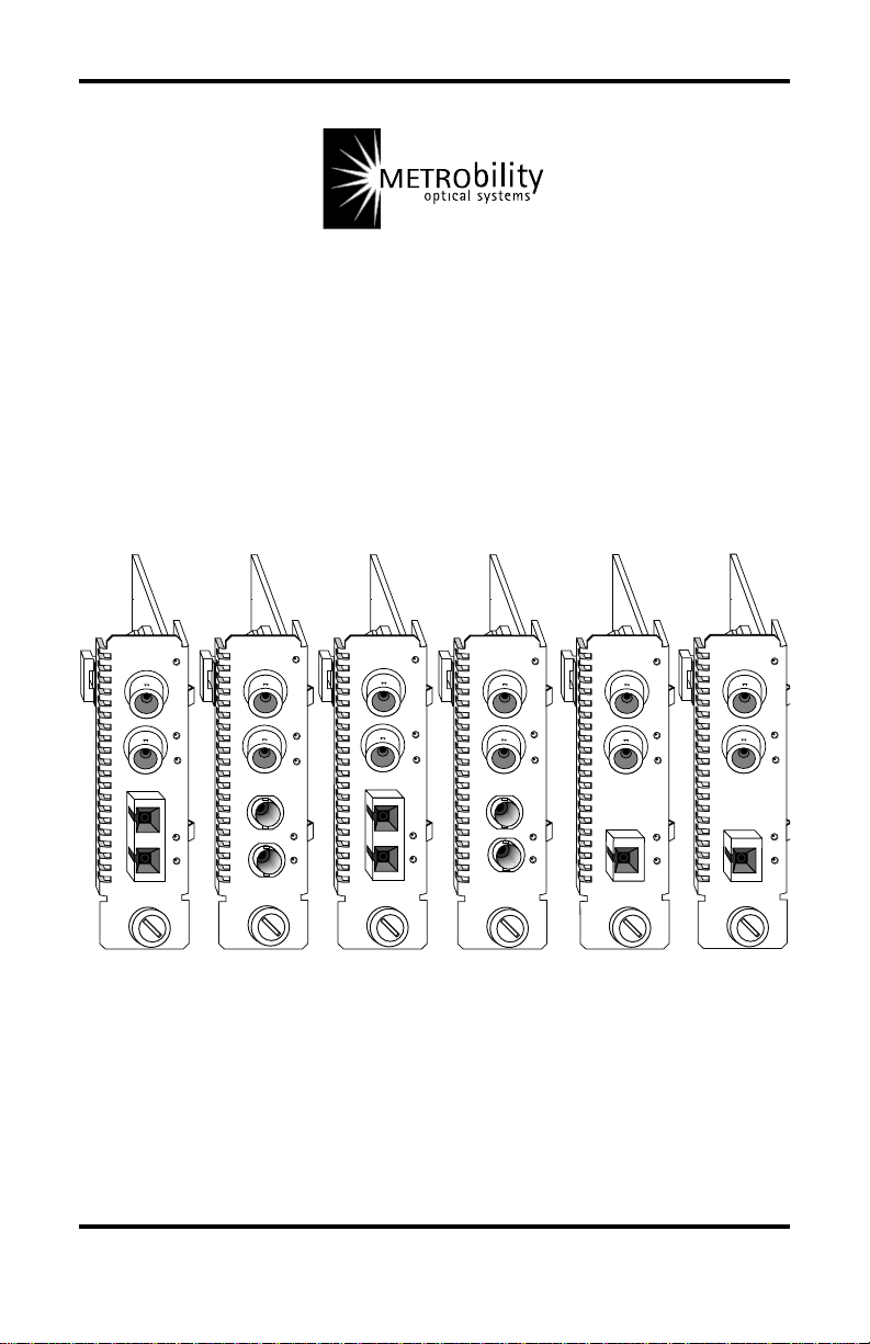
Radiance T3/E3 Single Interface Line Cards
T3 Copper to T3 Fiber:
R115-23 _____ T3 BNC to T3 multimode SC
R115-24 _____ T3 BNC to T3 singlemode SC
R115-25 _____ T3 BNC to T3 multimode ST
R115-26 _____ T3 BNC to T3 singlemode ST
R115-27 _____ T3 BNC to T3 singlemode SC (40km)
R115-2J______ T3 BNC to T3 singlemode SC (100km)
R115-2X _____ T3 BNC to T3 singlemode SC 1550/1310nm bidirectional wave-
R115-2Y _____ T3 BNC to T3 singlemode SC 1310/1550nm BWDM
E3 Copper to E3 Fiber:
R175-23 _____ E3 BNC to E3 multimode SC
R175-24 _____ E3 BNC to E3 singlemode SC
R175-25 _____ E3 BNC to E3 multimode ST
R175-26 _____ E3 BNC to E3 singlemode ST
R175-27 _____ E3 BNC to E3 singlemode SC (40km)
R175-2J _____ E3 BNC to E3 singlemode SC (100km)
R175-2X _____ E3 BNC to E3 singlemode SC 1550/1310nm BWDM
R175-2Y _____ E3 BNC to E3 singlemode SC 1310/1550nm BWDM
length division multiplexed (BWDM)
This publication is protected by the copyright laws of the United States and other countries, with all rights
reserved. No part of this publication may be reproduced, stored in a retrieval system, translated,
transcribed, or transmitted, in any form, or by any means manual, electric, electronic, electromagnetic,
mechanical, chemical, optical or otherwise, without prior explicit written permission of Metrobility Optical
Systems, Inc.
© 2002 Metrobility Optical Systems, Inc. All rights reserved. Printed in USA.

Table of Contents
Radiance T3/E3 Single Interface Line Cards Installation
& User Guide
Overview...............................................................................................................4
Installation Guide ................................................................................................ 5
STEP 1: Unpack the Line Card .....................................................................5
STEP 2: Set the Switches ..............................................................................5
STEP 3: Install the Line Card........................................................................ 6
STEP 4: Connect to the Network ..................................................................7
User Guide ........................................................................................................... 9
LED Indicators ..............................................................................................9
Theory of Operation .................................................................................... 10
Factory Settings...........................................................................................12
Link Loss Indications .................................................................................. 14
Loopback Modes ......................................................................................... 16
Topology Solutions ..................................................................................... 18
Technical Specifications .............................................................................. 19
Acronyms and Abbreviations......................................................................21
Product Safety, EMC and Compliance Statements .....................................22
Warranty and Servicing ...............................................................................23
Metrobility Optical Systems, the Metrobility Optical Systems logo, NetBeacon, and WebBeacon are
trademarks of Metrobility Optical Systems, Inc. All others are trademarks of their respective owners.
The information contained in this document is assumed to be correct and current. The manufacturer is
not responsible for errors or omissions and reserves the right to change specifications at any time
without notice.

Overview
Thank you for choosing the Radiance T3/E3 single interface line card.
The Metrobility Radiance T3/E3 line card provides high-speed integration and
conversion of T3 (44.736Mpbs) or E3 (34.368Mbps) coaxial telco communication lines to fiber transport environments. The copper data stream is converted to
optical signals for greater noise immunity and longer transmission. The T3/E3
line card supports remote fiber optic links up to 2km over multimode and up to
100km over singlemode cable.
To optimize your T3/E3 network, this hot-swappable media converter operates
seamlessly with low jitter. All signal activity is completely converted ensuring
accurate communication within connected segments. The Radiance T3 line card
features a user-selectable line build out, and all T3 and E3 models include
independent copper and fiber loopback modes to isolate problems within a
specific segment of the network.
Management options supported by the Radiance line cards include terminal
console commands, Metrobility’s GUI-based NetBeacon™ or WebBeacon
software, or any standard SNMP application. This ability provides remote
control over the line card’s configuration and immediate notification of a
problem to a management station.
The Radiance T3/E3 line card offers the following key features:
• B3ZS (T3) or HDB3 (E3) line code support on the coaxial interface.
• System and port LEDs on the front panel for easy diagnostics.
• Independent copper or fiber loopback mode that can be set with a DIP
switch or through software via local management.
• Individual port enable/disable.
• Line build out switch for short- or long-haul operation on the T3
models.
• Coaxial to multimode conversion up to 2km, coaxial to singlemode
conversion up to 100km, or coaxial to bidirectional wavelength
division multiplexed (BWDM) conversion up to 20km.
• Surge protection on the RX and TX ports of the coaxial interface.
• Low jitter for maximum transmission quality.
• Independent clocking on the RX and TX ports.
• Hot swappable.
• High MTBF.
™
4 Overview
Installation Guide
Follow the simple steps outlined in this section to install and start using
your Radiance T3/E3 single interface line card.
NOTE: Electrostatic discharge precautions should be taken when handling any
line card. Proper grounding is recommended (i.e., wear a wrist strap).
Unpack the Line Card
Your order has been provided with the safest possible packaging, but
1
shipping damage does occasionally occur. Inspect your order carefully.
If you discover any shipping damage, notify your carrier and follow
their instructions for damage and claims. Save the original shipping
carton if return or storage of the unit is necessary.
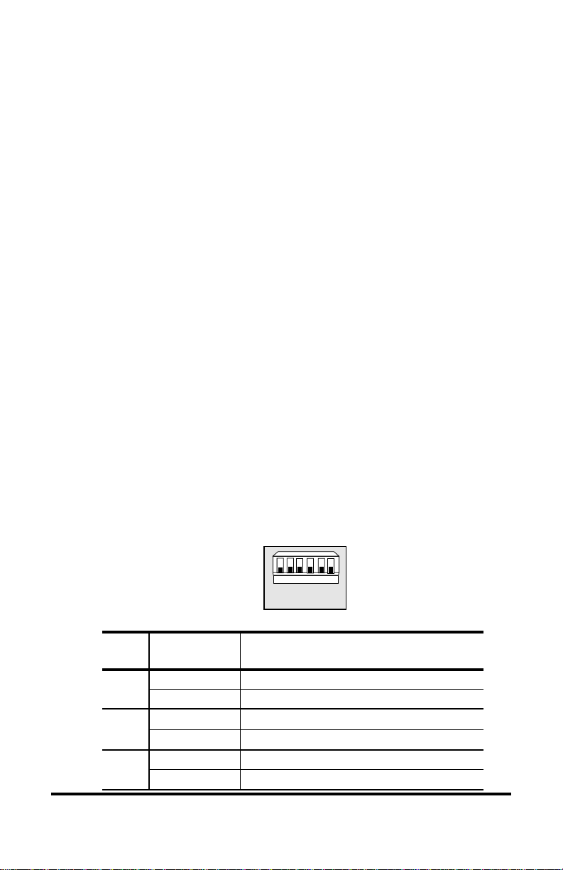
Set the Switches
A bank of DIP switches is located on the back of the card. On the T3
2
cards, three functional switches are clearly labeled and allow you to
select from several modes of operation. On the E3 board, only the
switches labeled CLP and FLP are functional. Unmarked switches are
inoperative. Refer to the table below for the proper setting of the DIP
switches.
When setting DIP switches, the UP position is when the lever of the
DIP switch is pushed away from the circuit board. The DOWN position
is when the lever is pushed toward the board.
*
1 65432
LBO
CLP
FLP
hctiwS
lebaL
OBL
)ylno3T(
PLC
PLF
*DIP switches also can be managed by console commands or via Metrobility’s NetBeacon or WebBeacon management software.
Refer to the
WebBeacon Management Software Installation & User’s Guide
Command Line Interface Reference Guide, NetBeacon Element Management Software Installation & User’s Guide
noitisoPnoitcnuF
PU.)tf0021-552(tuOdliuBeniLluahgnoL
NWOD )tluafed( .)tf552-0(tuOdliuBeniLluahtrohS
PU.tropreppocehtnodelbanesikcabpooL
NWOD )tluafed( .noitarepolamron;delbasidsikcabpoolreppoC
PU.tropcitporebifehtnodelbanesikcabpooL
NWOD )tluafed( .noitarepolamron;delbasidsikcabpoolcitporebiF
for software management information.
Radiance T3/E3 Single Interface Line Cards 5
or

LBO Switch (functional only on T3 cards)
Set the Line Build Out (LBO) switch up to support a long haul connection if the length of your coaxial cable is between 255 and 1200 feet.
Set LBO down to support a short haul connection if the length of your
coaxial cable is between 0 and 255 feet. The default setting is short
haul.
CLP Switch
The Copper Loopback (CLP) switch enables/disables loopback on the
copper port. When copper loopback is enabled, the incoming data and
clock are looped from the RX copper port to the TX copper port, thus
returning the copper input back to the sending device. At the same time,
the data is transmitted to the remote T3/E3 line card. However, data
from the remote card is ignored. Loopback is disabled by default. For
more information, refer to “Loopback Modes” in the User Guide
section of this manual.
FLP Switch
The Fiber Loopback (FLP) switch enables/disables loopback on the
fiber optic port. When fiber loopback is enabled, the incoming data and
clock are looped from the RX fiber port to the TX fiber port. The data
is also transmitted to the copper port, however, data from the copper
port is ignored. Loopback is disabled by default. For more information,
refer to “Loopback Modes” in the User Guide section of this manual.
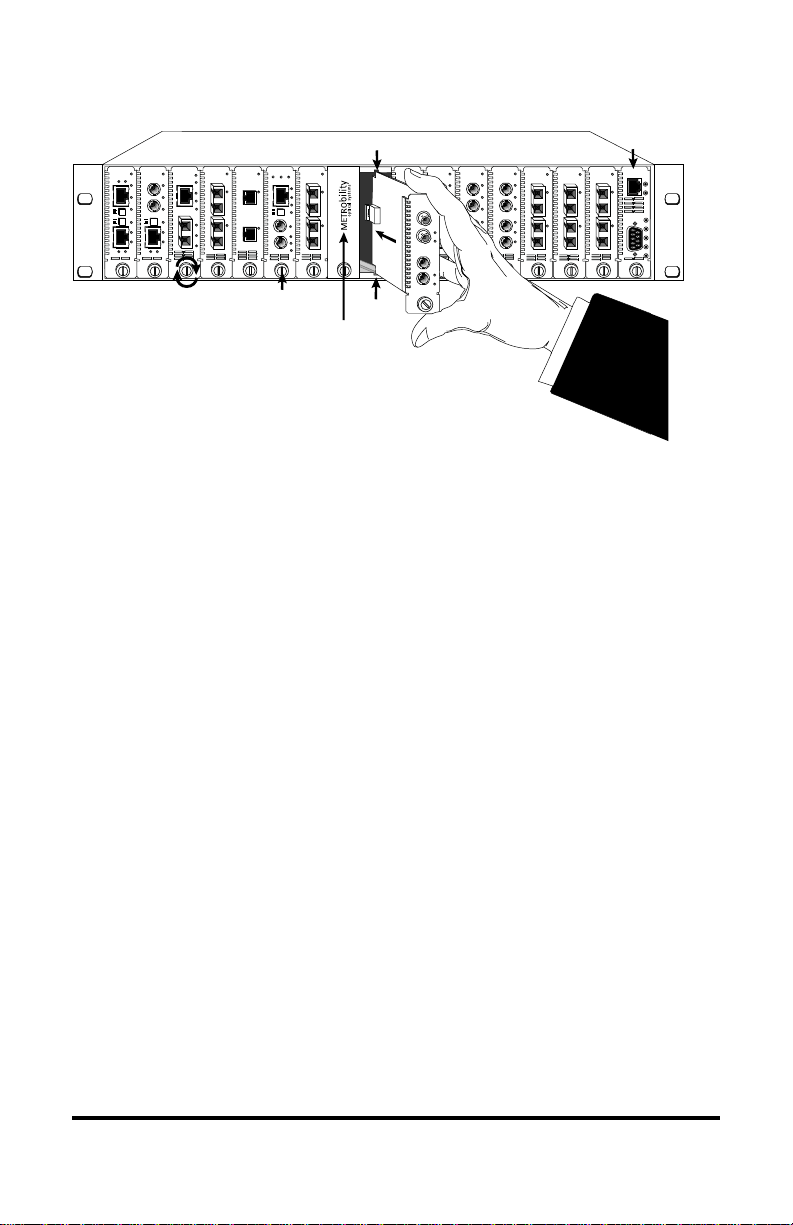
Install the Line Card
The Radiance T3/E3 line card offers the ease of plug-and-play installa-
3
6 Installation Guide
tion and is hot-swappable. The card must be firmly secured to the
chassis before network connections are made. Follow the simple steps
outlined below to install the line card.
• Grasp the card by the front panel as shown.
T1
PWR
PWR
MAN
FL
TX
RX
RXLK
RX
T
M
LK
X
M
LK
T
LBK
X
x
TX
II
FX
R
RX
X
R
RX
X
M
M
LK
S
M
LK
M
M
T
X
T
LBK
X
TX
IMPORTANT!
OC-12
10/100
100 FD
10/100
10/100
PWR
100 FD
RX
T
M
X
M
LK
x
II
TX
x
x
II
II
RX
LK
T
T
X
X
TX
100 FD
100 FD
Tighten thumb screw
to secure each card firmly
to chassis before making
network connections.
PWR
PWR
RX
LK
TX
LK
RX
LK
TX
FX
1000BASE
100 BASE
MAN FD PWR
PWR
SX
LK
T
M
X
M
x
II
LX
LK
L
S
H
M
FX
Thumb Screw
OC-12
RXLK
RX
M
M
LK
T
X
LBK
DIS
R
X
RX
S
M
LK
T
X
LBK
DIS
Card Guide
PWR
LK
Card Guide
Blank Panel
10/100
10/100
PWR
PWR
FL
FL
RX
M
M
E3
M
M
LK
TX
T
X
RX
LK
M
M
R
LK
M
M
X
LBK
FX
FX
R
R
X
X
LK
T
X
T
X
LBK
SM
10/100
10/100
10/100
PWR
PWR
FL
FL
FL
RX
RX
RX
M
M
M
M
M
M
LK
LK
LK
TX
TX
TX
RX
RX
RX
M
M
M
LK
LK
M
M
M
LK
TX
TX
TX
FX
FX
FX
Slot for Management Card
OC-12
PWR
RX
RXLK
M
M
LK
T
X
TX
RX
R
X
S
LK
M
T
X
TX
OC-12
OC-12
PWR
PWR
PWR
RXLK
RXLK
M
M
M
M
T
T
X
X
LK
LK
LK
R
R
X
X
S
S
M
M
T
T
X
X
T
P
C
O
N
S
O
L
E
• Insert the card into a slot in the chassis making sure that the top and
bottom edges of the board are aligned with the top and bottom card
guides in the chassis. Do not force the card into the chassis unnecessarily. It should slide in easily and evenly.
• Slide the line card in until the top and bottom edges of the front
panel are flush and even with the top and bottom edges of the
chassis.
• To secure the line card to the chassis, turn the thumbscrew clockwise
until it is snug. The card is now properly installed and ready for
connection to the network.
MGT-10
LK
AT
PWR
A
B
R
ER
4
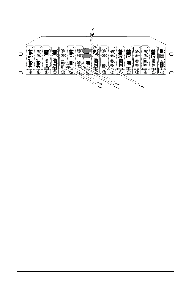
Connect to the Network
To connect the line card to the network, insert the cables into the
appropriate connectors as shown in the following illustration. Make
sure the card is secured to the chassis before making network connections. Once power is applied to the unit, correct connectivity can be
verified via the link (LK) LED.
When making network connections, make sure that the receive (RX)
port of the card connects to the transmit (TX) port of the connected
device, and make sure that the receive port of the connected device
connects to the transmit port of the line
card.
Radiance T3/E3 Single Interface Line Cards 7
10/100
100 BASE
10/100
PWR
PWR
PWR
100 FD
R
RX
RX
X
T
M
X
M
LK
LK
T
X
x
II
TX
TX
R
RX
RX
X
M
M
M
LK
LK
M
T
X
TX
TX
FX
FX
10/100
PWR
PWR
FL
100 FD
RX
LK
T
M
X
M
LK
AT
x
TX
II
RX
LK
M
M
LK
M
M
AT
TX
FX
FX
T
X
x
II
x
II
T
X
10/100
100 FD
100 FD
T1
10/100
PWR
PWR
FL
RX
M
M
LK
TX
x
II
RX
LK
T
X
TX
100 FD
E1
PWR
MAN
TX
TX
RX
RX
ALM
LK
LBK
TX
FX
FX
RX
R
R
RX
X
X
S
S
ALM
LK
M
M
T
T
LBK
X
X
TX
10/100
T3
PWR
PWR
MAN
T
RX
X
ALM
R
X
LBK
RX
R
X
ALM
LBK
T
X
MM
E3
10/100
PWR
100 FD
RX
T
X
LK
LK
x
LBK
II
TX
RX
M
LK
M
AT
TX
FX
PWR
PWR
100 FD
T
X
RX
LK
R
LBK
X
x
II
R
X
M
AT
M
T
FX
X
SM
T3
T1
TX
RX
LK
TX
FX
R
RX
X
M
LK
M
T
X
TX
10/100
10/100
PWR
MAN
PWR
PWR
FL
T
RX
X
ALM
R
X
LBK
RX
ALM
LBK
BWDM
100 FD
RX
T
M
LK
X
M
LK
x
LBK
TX
II
RX
M
M
LK
M
M
LK
TX
LBK
FX
Coaxial Interface
The coaxial interface provides two BNC connectors. The transmit (TX)
port is located above the receive (RX) port. Each connector supports a
maximum segment length of 1200 feet. Use only RG-59 cables.
Fiber Optic Interface
The line card’s fiber optic receive (RX) port is located above its
transmit (TX) port.
The fiber optic multimode (MM) interface supports a maximum
segment length of 2km for remote links.
The standard singlemode (SM) connector supports a maximum
segment length of 15km.
On the R115-27 and R175-27, the singlemode long haul interface
supports a maximum segment of 40km.
MGT-10
LK
T
P
RX
AT
LK
TX
PWR
RX
A
C
O
B
LK
N
S
O
R
TX
L
E
ER
On the R115-2J and R175-2J, the singlemode extended long haul
interface supports a maximum segment length of 100km.
BWDM Connection
The bidirectional wavelength division multiplexed (BWDM) port
provides one singlemode SC connector that supports a maximum
segment length of 20km. BWDM line cards must always be used in
complementary pairs. That is, a -2X model must always be connected
to a -2Y. The -2X cards are designed to transmit data at a wavelength of
1550nm and receive at 1310nm. Correspondingly, the -2Y cards
transmit data at 1310nm and receive at 1550nm.
8 Installation Guide
 Loading...