

Metrobility R105-13,R105-14,R105-15,R105-16,R105-17,R105-1J,R165-13,R165-14,R165-15,R165-16,R165-17,R165-1J User guide

RADIANCE
T1/E1
SINGLE INTERFACE LINE CARDS
T1
MAN
PWR
TX
RX
LK
MM
LBK
R
X
RX
LK
T
X
LBK
E1
MAN
PWR
TX TX
RX
LK
SM
LBK
R
X
RX
LK
T
X
LBK
T1
MAN
PWR
RX
LK
MM
LBK
R
X
RX
LK
T
X
LBK
E1
MAN
PWR
TX
RX
LK
LBK
SM
R
X
RX
T
LK
X
LBK
Installation & User Guide
Models: R105-13 / R105-14 / R105-15 / R105-16 /
R105-17 / R105-1J / R165-13 / R165-14 /
R165-15 / R165-16 / R165-17 / R165-1J

Radiance T1/E1 Single Interface Line Cards
T1 Copper to T1 Fiber:
R105-13 _____ T1 RJ-45 to T1 multimode SC
R105-14 _____ T1 RJ-45 to T1 singlemode SC
R105-15 _____ T1 RJ-45 to T1 multimode ST
R105-16 _____ T1 RJ-45 to T1 singlemode ST
R105-17 _____ T1 RJ-45 to T1 singlemode SC (40km)
R105-1J _____ T1 RJ-45 to T1 singlemode SC (100km)
E1 Copper to E1 Fiber:
R165-13 _____ E1 RJ-45 to E1 multimode SC
R165-14 _____ E1 RJ-45 to E1 singlemode SC
R165-15 _____ E1 RJ-45 to E1 multimode ST
R165-16 _____ E1 RJ-45 to E1 singlemode ST
R165-17 _____ E1 RJ-45 to E1 singlemode SC (40km)
R165-1J _____ E1 RJ-45 to E1 singlemode SC (100km)
This publication is protected by the copyright laws of the United States and other countries, with all rights
reserved. No part of this publication may be reproduced, stored in a retrieval system, translated,
transcribed, or transmitted, in any form, or by any means manual, electric, electronic, electromagnetic,
mechanical, chemical, optical or otherwise, without prior explicit written permission of Metrobility Optical
Systems, Inc.
© 2003 Metrobility Optical Systems, Inc. All rights reserved. Printed in USA.

Table of Contents
Radiance T1/E1 Single Interface Line Cards Installation
& User Guide
Overview...............................................................................................................4
Installation Guide ................................................................................................ 5
STEP 1: Unpack the Line Card .............................................................. 5
STEP 2: Set the Switches ....................................................................... 5
MDI-II to MDI-X Switch ...............................................................5
DIP Switches...................................................................................6
STEP 3: Install the Line Card ................................................................8
STEP 4: Attach the Adapters..................................................................8
STEP 5: Connect to the Network ...........................................................9
User Guide ......................................................................................................... 10
LED Indicators ..................................................................................... 10
Software Port Indicators.......................................................................11
Theory of Operation.............................................................................12
Factory Settings....................................................................................13
Link Loss Indications...........................................................................14
Diagnostic Modes ................................................................................16
Topology Solutions ..............................................................................19
Technical Specifications....................................................................... 20
Acronyms and Abbreviations...............................................................22
Product Safety, EMC and Compliance Statements.............................. 23
Warranty and Servicing ........................................................................ 24
Metrobility Optical Systems, the Metrobility Optical Systems logo, NetBeacon, “twister” and WebBeacon
are trademarks of Metrobility Optical Systems, Inc.
The information contained in this document is assumed to be correct and current. The manufacturer is
not responsible for errors or omissions and reserves the right to change specifications at any time
without notice.

Overview
Thank you for choosing the Radiance T1/E1 single interface line card.
The Radiance T1/E1 line card from Metrobility Optical Systems provides highspeed integration and conversion of T1 (1.544Mbps) or E1 (2.048Mbps) serial
copper telco communication lines to fiber transport environments. Regardless of
the line codes or framing, the copper data stream is converted to optical signals
for greater noise immunity and longer transmission. The T1/E1 line card
supports remote fiber optic links up to 2km over multimode and up to 100km
over singlemode cable.
To optimize your T1/E1 network, this hot-swappable media converter operates
seamlessly with a low bit delay. All signal activity is completely converted
ensuring accurate communication within connected segments. The Radiance T1/
E1 line card is totally frame and data independent and features user-selectable
line build out.
For testing a full-duplex fiber optic link, the T1/E1 line card is designed with a
built-in Bit Error Rate Test (BERT). Management of the line card allows a
managed device to obtain information without consuming valuable user bandwidth. Management options supported by the Radiance T1/E1 line cards include
terminal console commands, Metrobility’s GUI-based NetBeacon™ or WebBeacon™ software, or any SNMP application. This ability provides remote control
over the line card’s configuration and immediate notification of a problem to a
management station.
The Radiance T1/E1 line card offers the following key features:
• AMI or B8ZS (T1) / HDB3 (E1) bipolar line code support on the
copper interface.
• Eight LED indicators for easy visual diagnostics.
• Local and remote loopback monitoring plus BERT 511 testing.
• Variable line length selection to set the proper T1/E1 pulse shape.
• MDI-II to MDI-X switch on the copper port to eliminate the need for
crossover cables.
• Copper to multimode conversion up to 2km, or copper to singlemode
conversion up to 100km.
• Far End Fault notification.
• Low jitter for maximum transmission quality.
• Low power consumption (≤ 3W).
• Hot swappable.
4 Overview
Installation Guide
Follow the simple steps outlined in this section to install and start using
your Radiance T1/E1 single interface line card.
NOTE: Electrostatic discharge precautions should be taken when handling any
line card. Proper grounding is recommended (i.e., wear a wrist strap).
Unpack the Line Card
Check that the following components have been included in your order:
1
• Radiance T1/E1 single interface line card
• 2 SC-to-ST adapters (R105-16 and R165-16 only)
Your order has been provided with the safest possible packaging, but
shipping damage does occasionally occur. Inspect your order carefully.
If you discover any shipping damage, notify your carrier and follow
their instructions for damage and claims. Save the original shipping
carton if return or storage of the unit is necessary.
Set the Switches
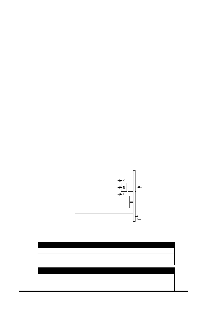
MDI-II/MDI-X Switch
2
To eliminate the need for crossover cables, the T1/E1 line card features
an MDI-II/MDI-X switch for its copper port. The switch is located
directly behind its associated RJ-45 connector. Use the slide switch to
configure the port for either a straight-through or crossover connection.
MDI-X Position
Slide Switch
MDI-II Position
(default)
RJ-45
• The parallel symbol (II) indicates a straight-through or parallel
connection. (default)
• The cross symbol (X) indicates a crossover connection.
A device that is wired straight through needs one crossover connection:
If the cable is
straight through
crossover
A device that is wired crossover needs a parallel connection:
If the cable is
straight through
crossover
Radiance T1/E1 Single Interface Line Cards 5
the MDI-II to MDI-X switch setting should be
X
II
the MDI-II to MDI-X switch setting should be
II
X
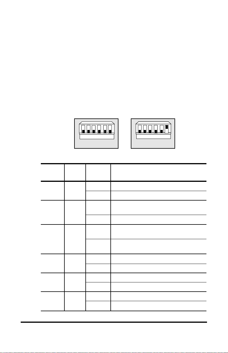
DIP Switches
A bank of six DIP switches is located on the back of the card. The
switches allow you to select from several modes of operation and to set
the transmitter’s output pulse shape. Refer to the table below for the
proper setting of the DIP switches.
When setting DIP switches, the UP position is when the lever of the
DIP switch is pushed away from the circuit board. The DOWN position
is when the lever is pushed toward the board. Shown below are the
default switch settings for the T1 and E1 boards.
Default T1 Settings Default E1 Settings
*
hctiwS
rebmuN
1RB
2BL
3DC
42L
51L
60L
1
BRLBCDL2L1
hctiwS
lebaL
65432
L0
1
BRLBCDL2L1
noitisoPnoitcnuF
PU.delbanesi)TREB(tseTetaRrorrEtiB
NWOD.noitarepolamron;delbasidsiTREB
PU
NWOD.noitarepolamron;delbasidsikcabpooL
PU
NWOD
PUsi2tibhtgneleniL 1.
NWODsi2tibhtgneleniL 0.
PUsi1tibhtgneleniL 1.
NWODsi1tibhtgneleniL 0.
PUsi0tibhtgneleniL 1.
NWODsi0tibhtgneleniL 0.
.strop
65432
L0
rebifdnareppocehtnodelbanesikcabpooL
signidocenil)IMA(noisrevnIkraMetanretlA
.atadgnittimsnartdnagniviecerrofdesu
desusignidocenil)1E(3BDHro)1T(SZ8B
.atadgnittimsnartdnagniviecerrof
*DIP switches also can be managed by console commands or with Metrobility NetBeacon or WebBeacon management software.
Refer to the
WebBeacon Management Software Installation & User’s Guide
Command Line Interface Reference Guide, NetBeacon Element Management Software Installation & User’s Guide
for software management information.
6 Installation Guide
or

BR Switch
Use the Bit Error Rate Test switch to test the fiber optic connection
between two T1/E1 line cards. If BERT 511 is enabled on the locally
managed card, it will generate a 511 pattern on the data channel and
request temporary loopback via the management channel. The remote
card will then put itself into loopback on the fiber port and send the
BERT data back to the local card. The default state of the BERT switch
is disabled (down).
LB Switch
The LB switch enables local loopback which isolates the copper side
from the fiber side. This allows the incoming data on each side to loop
back on their own media line and return to their sending devices. The
default state of the local loopback switch is disabled (down). For more
information, refer to “Diagnostic Modes” in the User Guide section.
CD Switch
The line code switch determines whether AMI or B8ZS / HDB3 coding
is used for receiving and transmitting data. The default setting is B8ZS
for a T1 card and HDB3 for an E1 card. These are the settings used in
most applications. AMI (bipolar) coding is common in legacy applications.
L2, L1 and L0 Switches
These switches determine the shape of the transmitter’s output pulse.
The default is 0, 0, 0 for T1 and 0, 0, 1 for E1.
(0 = down; 1 = up)
2L1L0LtuOdliuBeniL1TtuOdliuBeniL1E
000 USCBd0/)tf331-0(1-XSD
001 )tf662-331(1-XSDlamronsmho021
010 )tf993-662(1-XSD
011 )tf335-993(1-XSD
100 )tf556-335(1-XSD
10 1 USCBd5.7110 USCBd51111 USCBd5.22-
Radiance T1/E1 Single Interface Line Cards 7
3
Install the Line Card
The Radiance T1/E1 line card offers the ease of plug-and-play installation and is hot-swappable. The card must be firmly secured to the
chassis before network connections are made. Follow the simple steps
outlined below to install your line card.
• Grasp the card by the front panel as shown.
OC-12
10/100
T
X
x
II
x
II
T
X
100 FD
100 FD
10/100
T1
10/100
PWR
PWR
PWR
to secure each card firmly
to chassis before making
MAN
FL
100 FD
TX
RX
RXLK
RX
RX
LK
TX
RX
LK
TX
Tighten thumb screw
M
M
LK
TX
FX
x
R
II
X
RX
M
M
LK
T
T
X
X
TX
100 FD
IMPORTANT!
T
M
LK
X
M
T
LBK
X
x
II
RX
R
X
LK
S
M
M
M
T
LBK
X
network connections.
PWR
PWR
RX
LK
TX
LK
RX
LK
TX
FX
1000BASE
100 BASE
MAN FD PWR
PWR
SX
LK
T
M
X
M
x
II
LX
LK
L
S
H
M
Thumb Screw
FX
OC-12
RXLK
RX
M
M
LK
T
X
LBK
DIS
R
X
RX
S
M
LK
T
X
LBK
DIS
Card Guide
PWR
LK
Card Guide
Blank Panel
10/100
10/100
PWR
PWR
FL
FL
RX
M
M
E1
M
M
LK
MAN
PWR
TX
TX
RX
RX
M
M
LK
M
M
LK
SM
LBK
TX
R
FX
FX
X
R
RX
X
LK
T
X
T
X
LBK
10/100
10/100
10/100
PWR
PWR
FL
FL
FL
RX
RX
RX
M
M
M
M
M
M
LK
LK
LK
TX
TX
TX
RX
RX
RX
M
M
M
LK
LK
M
M
M
LK
TX
TX
TX
FX
FX
FX
Slot for Management Card
OC-12
PWR
RX
RXLK
M
M
LK
T
X
TX
RX
R
X
S
LK
M
T
X
TX
OC-12
OC-12
PWR
PWR
PWR
RXLK
RXLK
M
M
M
M
T
T
X
X
LK
LK
LK
R
R
X
X
S
S
M
M
T
T
X
X
MGT-10
LK
T
P
AT
PWR
A
C
O
B
N
S
O
R
L
E
ER
• Insert the card into a slot in the chassis making
sure that the top and bottom edges of the board
are aligned with the top and bottom card guides in
the chassis. Do not force the card into the chassis
unnecessarily. It should slide in easily and evenly.
• Slide the card in until the top and bottom edges of the front panel are
flush and even with the top and bottom edges of the chassis.
• To secure the line card to the chassis, turn the thumbscrew clockwise
until it is snug. The card is now properly installed and, excluding the
R105-16 and R165-16, ready for network connections.
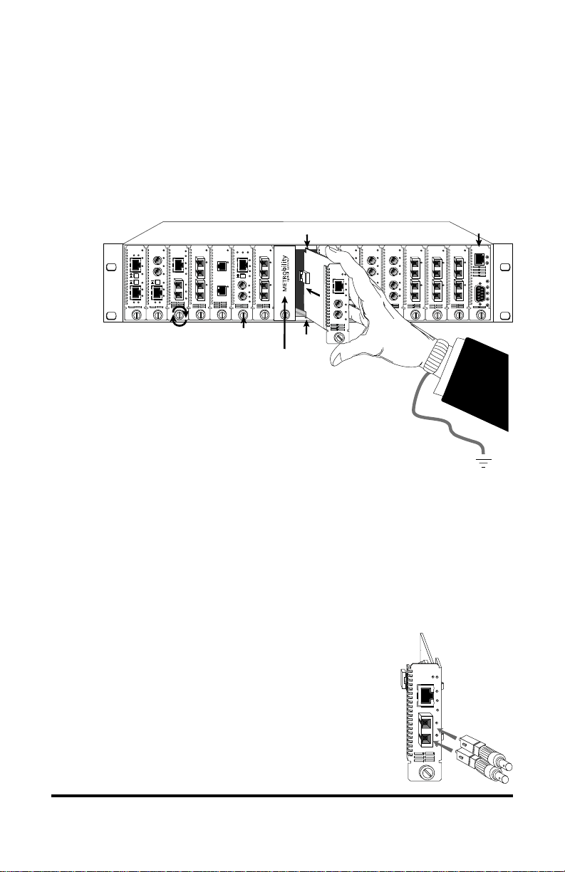
Attach the Adapters
(R105-16, R165-16 Only)
4
8 Installation Guide
The fiber ports on these models are equipped with
SC connectors and require two SC-to-ST adapters,
which are included with your order.
To connect the adapters to the line card, first
remove the protective coverings from both ends of
T1
MAN
PWR
TX
RX
LK
MM
LBK
R
X
RX
LK
T
X
LBK
 Loading...