

RADIANCE
CHASSIS STACKING
LINE CARD
10/100 BASE
PWR
1
2
3
4
LK
AT
LK
AT
LK
AT
LK
AT
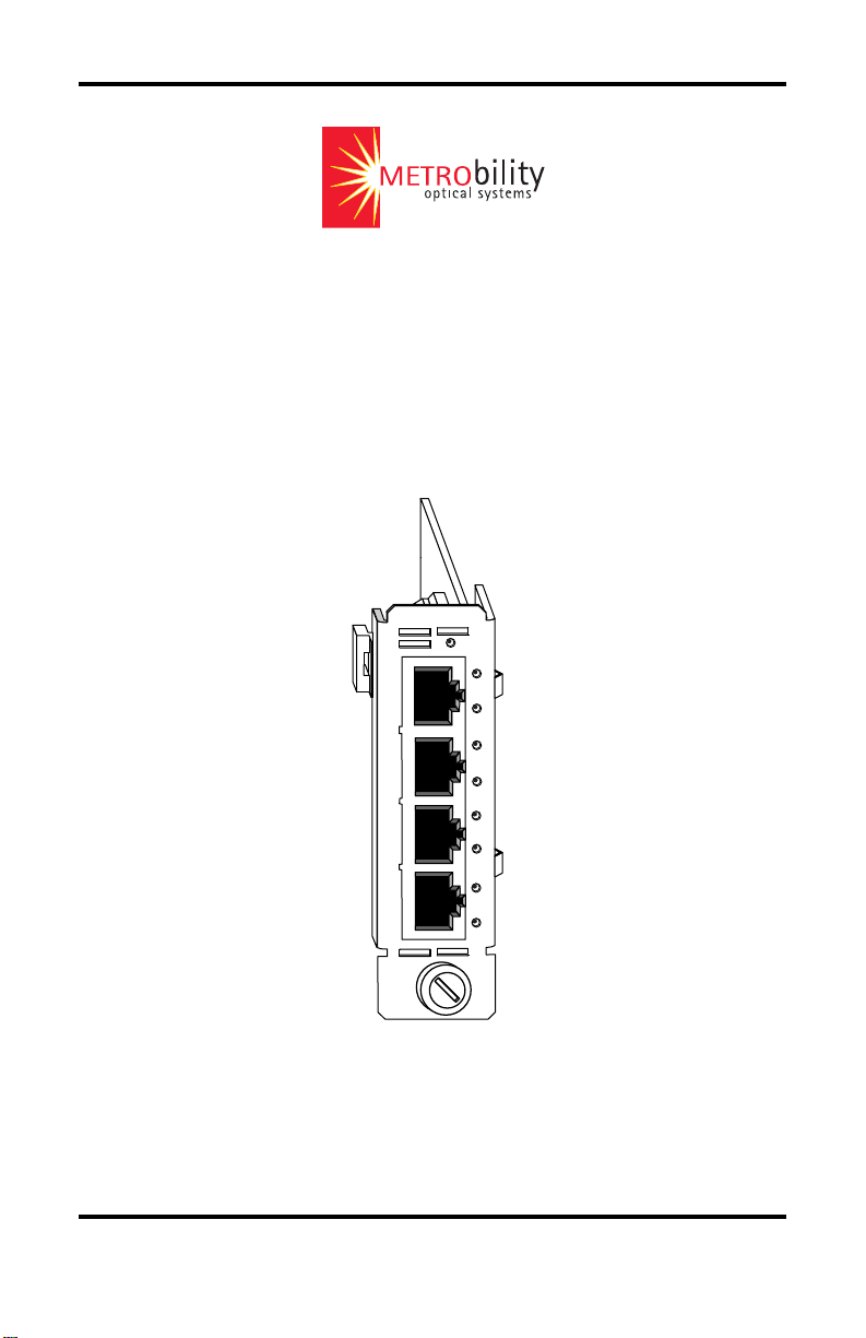
Installation & User Guide
Model: R104-11

Radiance Chassis Stacking Line Card
R104-11 ____ 10/100Mbps Four-Port TX Switch
This publication is protected by the copyright laws of the United States and other countries, with all rights
reserved. No part of this publication may be reproduced, stored in a retrieval system, translated,
transcribed, or transmitted, in any form, or by any means manual, electric, electronic, electromagnetic,
mechanical, chemical, optical or otherwise, without prior explicit written permission of Metrobility Optical
Systems, Inc.
© 2003 Metrobility Optical Systems, Inc. All rights reserved. Printed in USA.

Table of Contents
Radiance Chassis Stacking Line Card Installation & User
Guide
Overview..............................................................................................................4
Installation Guide ...............................................................................................5
STEP 1: Unpack the Line Card ..............................................................5
STEP 2: Set the Switches .......................................................................5
STEP 3: Install the Card.........................................................................9
STEP 4: Connect to the Network .........................................................10
User Guide......................................................................................................... 11
LED Indicators .....................................................................................11
Full-Duplex Flow Control (FDFL) ...................................................... 11
Topology Solutions .............................................................................. 12
Chassis Stacking Example ...................................................................13
Technical Specifications.......................................................................14
Product Safety, EMC and Compliance Statements..............................15
Warranty and Servicing........................................................................16
Metrobility Optical Systems, the Metrobility Optical Systems logo, NetBeacon and WebBeacon are
trademarks of Metrobility Optical Systems, Inc. All others are trademarks of their respective owners.
The information contained in this document is assumed to be correct and current. The manufacturer is
not responsible for errors or omissions and reserves the right to change specifications at any time
without notice.

Overview
The Radiance Chassis Stacking Line Card is a four-port 10/100Mbps TX
switch that provides a cost-effective solution for situations in which a simple
switching option with few ports is required. When configured for stacking in a
Metrobility chassis, the card eliminates the need for any external equipment.
This means the network administrator has one less piece of networking hardware to manage and monitor.
The Radiance chassis stacking line card is designed to support a stack of up to
four Metrobility chassis, thus enabling communication between the management
card in each chassis. The stacking line card enables up to 126 local ports and up
to 126 remote ports (using Radiance access line cards) to be managed under a
single IP address. This ability provides visibility and remote software control
over the entire stack, along with notification of a problem or failure to the
network administrator.
Each 10/100Mbps Ethernet port supports auto-negotiation of both duplex and
speed, as well as half and full duplex flow control. Additionally, each port
includes automatic cross-over functionality, which eliminates the need for crossover cables, for easier network setup.
The Radiance chassis stacking line card offers the following key features:
• Auto-negotiation to determine the best duplex and speed for data
communications.
• 10/100Mbps speed control.
• Backpressure flow control in half-duplex mode.
• Pause frame flow control in full-duplex mode (configurable through
software only).
• Built-in crossover functionality that eliminates the need for crossover
cables.
•1M bit buffer of built-in memory.
• Full compliance with applicable sections of IEEE 802.3, IEEE 802.3u
and IEEE 802.x standards.
•A non-blocking, high performance switching engine with the ability to
learn up to 1,024 MAC addresses.
• Support for long packets (up to 1518 bytes for un-tagged frames or up
to 1522 bytes for IEEE 802.3ac tagged frames).
4 Overview
Installation Guide
Follow the simple steps outlined in this section to install and start using the
Radiance chassis stacking line card.
NOTE: Electrostatic discharge precautions should be taken when handling any
circuit board. Proper grounding is recommended (i.e., wear a wrist strap).
Unpack the Line Card
Your order has been provided with the safest possible packaging, but
1
shipping damage does occasionally occur. Inspect your card carefully.
If you discover any shipping damage, notify your carrier and follow
their instructions for damage and claims. Save the original shipping
carton if return or storage of the unit is necessary.
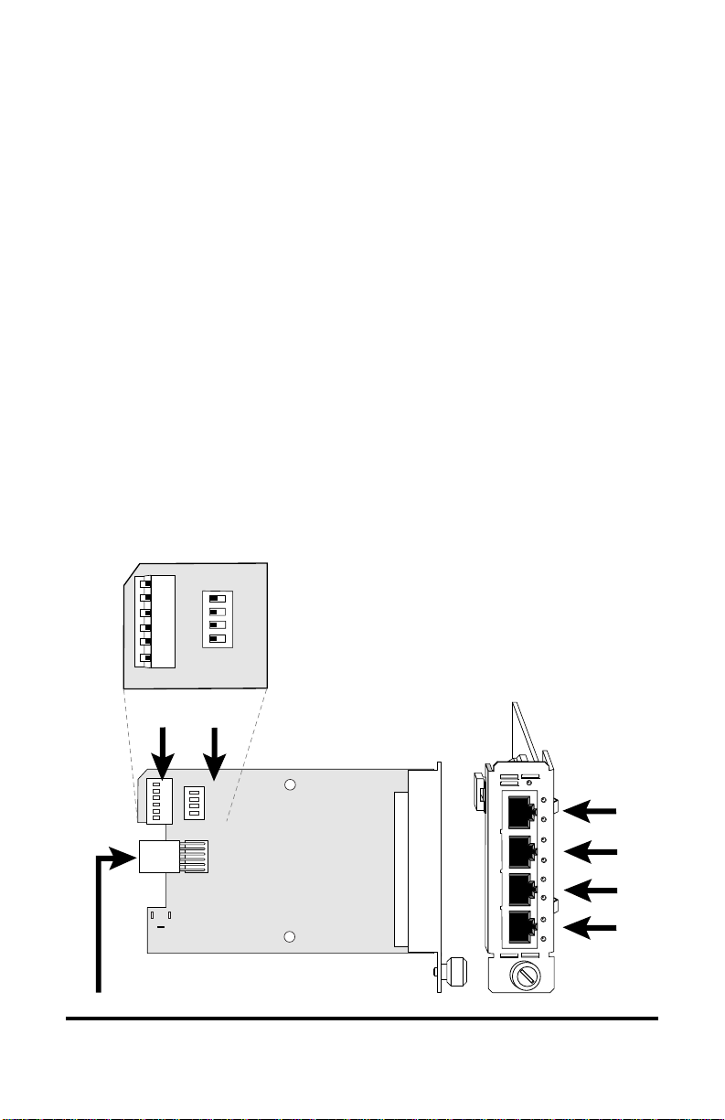
Set the Switches
Two sets of DIP switches, located on the back of the circuit board,
2
allow you to select from several modes of operation. These switches
are clearly marked on the printed circuit board.
---------------------- OPEN ----------------------
1 2 3 4 5 6
Power Connector
100M2
-----------OPEN-----------
AN2
100M3
AN3
100M4
UP
AN4
DOWN
SW2
DIP
switches
1 2 3 4
FD
SW1
Default Switch Settings
100M1
AN1
HDFL
SW1 SW2
HDFL = OPEN AN4 = OPEN
FD = OPEN 100M4 = OPEN
AN1 = OPEN AN3 = OPEN
100M1 = OPEN 100M3 = OPEN
10/100 BASE
1
2
3
4
AN2 = OPEN
100M2 = OPEN
PWR
LK
AT
LK
AT
LK
AT
LK
AT
Radiance Chassis Stacking Line Card 5
Port 1
Port 2
Port 3
Port 4
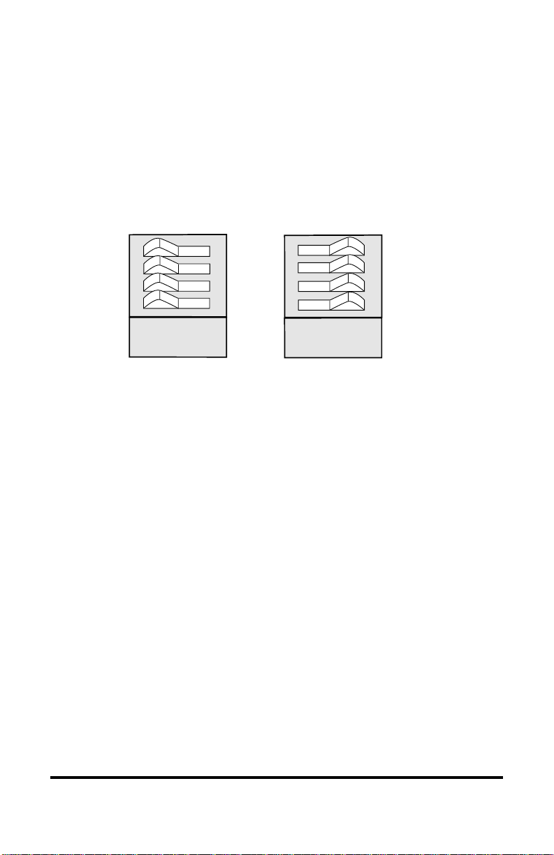
When setting DIP switches* on SW2, the OPEN position is when the
lever of the switch is pushed up toward the word “OPEN.” The
CLOSED position is when the lever is pushed down toward the board.
On the rocker DIP switch (SW1), the OPEN position is when the
“OPEN” side of the switch is down and the numbered side is up. The
CLOSED position is when the numbered side of the switch is down and
the “OPEN” side is up. See illustration below.
HDFL
AN1
100M1
FD
1 2 3 4
-----------OPEN-----------
OPEN
HDFL
AN1
100M1
FD
1 2 3 4
CLOSED
-----------OPEN-----------
Auto-Negotiation Switch (AN1, AN2, AN3, AN4)
Switch ANx controls the use of auto-negotiation on its associated port
(e.g., AN1 sets auto-negotiation on Port 1). To enable auto-negotiation,
the switch must be OPEN. To disable this function, the switch must be
CLOSED. By default, auto-negotiation is enabled.
When auto-negotiation is enabled on a port, it advertises 10/100Mbps
half/full duplex capabilities. When auto-negotiation is disabled, the
port’s duplex is determined by the FD switch setting, and its speed is
set by its corresponding 100Mx switch.
Speed Switch (100M1, 100M2, 100M3, 100M4)
The 100Mx speed switch controls the speed setting on its associated
port (e.g., 100M2 determines the speed on Port 2). If auto-negotiation is
disabled on a Port x, its speed will be set to one of the following:
• 100Mbps if the 100Mx switch is OPEN. (default)
• 10Mbps if the 100Mx switch is CLOSED.
When auto-negotiation is enabled, the 100Mx switch is ignored.
*DIP switches also can be managed via console commands or with Metrobility’s NetBeacon™ or WebBeacon™
management software. Refer to the
Software Installation & User’s Guide
management information.
Command Line Interface Reference Guide, NetBeacon Element Management
or
WebBeacon Management Software Installation & User’s Guide
for software
6 Installation Guide

Duplex Switch (FD)
Switch FD determines the duplex mode on all ports that have autonegotiation disabled.
• The ports will operate at full duplex if FD is OPEN. (default)
• They will operate at half duplex if FD is CLOSED.
If auto-negotiation is enabled on a port, that port will ignore the FD
switch setting.
For example, if FD is enabled and auto-negotiation is disabled on Ports
1 and 2 and enabled on Ports 3 and 4, then Ports 1 and 2 will operate at
full duplex, while Ports 3 and 4 will ignore the FD switch setting. The
duplex mode for Ports 3 and 4 will be determined through the autonegotiation process.
Half-Duplex Flow Control Switch (HDFL)
For ports operating at half duplex, the Radiance chassis stacking line
card provides an option to enable half-duplex flow control
(backpressure). When half-duplex flow control is activated, the
Radiance card generates a jamming pattern to force a collision on a port
if a buffer cannot be allocated for the port’s incoming packets. Halfduplex flow control is enabled by default (OPEN).
The HDFL switch must be CLOSED to disable half-duplex flow
control on all four ports. The switch must be OPEN to enable HDFL on
all ports.
Radiance Chassis Stacking Line Card 7

The table below displays sample port configurations and the DIP switch
settings used to obtain them. The configuration column gives the autonegotiation, speed and duplex options for each port. By default, all four
ports are set to auto-negotiate.
noitarugifnoC1troP2troP3troP4troP
1troP2troP3troP4troPDF1NA1M0012NA2M0013NA3M0014NA4M001
NA NA NA NA + + + +
NANANAlluF001++ + + —+
NA NA NA flaH001 — + + + — +
NANANAlluF01++ + + ——
NA NA NA flaH01 — + + + — —
NANAlluF001lluF001++ + —+—+
NA NA lluF001 lluF01 + + + — + — —
NANAflaH001flaH001—+ + —+—+
NA NA lluF01 lluF01 + + + — — — —
NANAflaH01flaH001—+ + ———+
NA lluF001 lluF001 lluF001 + + — + — + — +
NAflaH001flaH001flaH001—+ —+—+—+
NA lluF001 lluF01 lluF001 + + — + — — — +
NAflaH01flaH001flaH01—+ ———+——
NA lluF01 lluF01 lluF01 + + — — — — — —
NAflaH01flaH01flaH01—+ ——————
lluF001 lluF001 lluF001 lluF001 + — + — + — + — +
flaH001flaH001flaH001flaH001——+—+—+—+
lluF01 lluF01 lluF01 lluF01 + — — — — — — — —
flaH01flaH01flaH01flaH01—————————
lluF01 lluF001 lluF01 lluF001 + — — — + — — — +
flaH01flaH001flaH01flaH001————+———+
lluF01 lluF01 lluF001 lluF001 + — — — — — + — +
flaH001flaH001flaH01flaH01——+—+————
AN indicates that auto-negotiation is enabled.
+ indicates the switch is enabled (OPEN) .
— indicates the switch is disabled (CLOSED).
A blank space indicates that the switch setting is not applicable and
can be either OPEN or CLOSED.
8 Installation Guide

3
Install the Card
The Radiance chassis stacking line card offers the ease of plug-andplay installation and is hot-swappable. The unit must be firmly secured
to the chassis before network connections are made. Follow the simple
steps outlined below to install the card.
• Grasp the card by the front panel as shown.
Slot for Management Card
10/100
10/100
10/100
PWR
PWR
FL
FL
M
M
M
M
M
M
M
M
FX
FX
OC-12
PWR
FL
RX
RX
RX
RXLK
M
M
M
M
LK
LK
LK
T
X
TX
TX
TX
RX
RX
RX
R
X
M
S
LK
LK
LK
M
M
T
X
TX
TX
TX
FX
OC-12
PWR
PWR
RXLK
M
M
T
X
LK
LK
R
X
S
M
T
X
10/100
10/100
PWR
PWR
FL
100 FD
RX
T
M
X
M
LK
x
II
TX
x
x
II
II
RX
LK
T
T
X
X
TX
100 FD
100 FD
IMPORTANT!
Tighten thumb screw
to secure each card firmly
to chassis before making
network connections.
OC-12
10/100
10/100
PWR
100 FD
100 FD
RXLK
RX
RX
T
T
M
X
X
M
LK
LK
T
X
x
x
TX
II
TX
II
R
RX
RX
X
S
M
M
LK
M
LK
M
M
T
X
TX
TX
FX
PWR
PWR
RX
LK
TX
LK
RX
LK
TX
FX
1000BASE
1000BASE
PWR
SX
SX
LK
M
M
M
M
LX
LX
LK
R
X
S
S
M
M
T
X
Thumb Screw
PWR
LK
LK
Card Guide
OC-12
PWR
RXLK
M
M
T
X
LK
R
X
S
M
T
X
Blank Panel
Card Guide
10/100
10/100
PWR
PWR
FL
FL
RX
RX
M
M
10/100 BASE
M
M
LK
LK
PWR
TX
TX
LK
1
AT
RX
RX
M
M
LK
LK
M
M
LK
2
AT
TX
TX
FX
FX
LK
R
3
X
AT
T
X
LK
4
AT
• Insert the card into a slot on the chassis making sure that the top
and bottom edges of the board are aligned with the top and bottom
card guides in the chassis. Do not force the card into the chassis
unnecessarily. It should slide in easily and evenly.
• Slide the board in until the top and bottom edges of the front panel
are flush and even with the top and bottom edges of the chassis.
OC-12
RXLK
M
M
T
X
R
X
S
M
T
X
MGT-10
PWR
LK
1
AT
LK
2
AT
PWR
LK
A
C
O
B
N
S
O
R
L
E
ER
•To secure the card to the chassis, turn the thumbscrew clockwise
until it is snug. The unit is now properly installed and ready for
connection to the network.
Radiance Chassis Stacking Line Card 9

4
Connect to the Network
To connect the Radiance chassis stacking line card to the network,
insert the twisted-pair cables into the appropriate connectors. Be sure
the card is secured to the chassis by tightening the thumbscrew before
making network connections.
The Radiance chassis stacking line card provides four shielded RJ-45
connectors that support a maximum segment length of 100 meters. Use
Category 3, 4 or 5 cables for 10Mbps segments; use only Category 5 or
5E cables for 100Mbps segments.
Insert your connectors as shown below. Once power is applied to the
card, correct connectivity can be verified via the link (LK) LED, if an
active device is connected to the remote end of the cable.
10/100
10/100
10/100
10/100
T
X
x
II
M
M
100 FD
PWR
PWR
100
100 FD
RX
RX
T
T
X
X
LK
LK
x
x
II
II
TX
TX
RX
RX
M
LK
M
LK
TX
TX
SM
FX
FX
PWR
RX
LK
TX
RX
LK
TX
10/100
MGT-10
PWR
PWR
100 FD
FD
100 FD
1
RX
RX
LK
TX
RX
LK
TX
RX
T
T
X
X
LK
LK
x
II
M
M
2
x
TX
II
TX
RX
RX
C
O
M
N
LK
LK
M
S
O
TX
TX
L
E
FX
FX
T
X
T
X
100 FD
x
II
x
II
100 FD
10/100
PWR
FL
RX
M
M
LK
TX
x
II
RX
LK
T
X
TX
100 FD
10/100
PWR
100
FD
FD
100 FD
RX
RX
T
T
X
X
LK
LK
x
x
II
TX
TX
II
RX
RX
M
LK
LK
M
TX
TX
MM
FX
10/100
10/100
10/100
10/100
PWR
100 FD
RX
T
X
LK
x
TX
II
RX
M
LK
M
TX
10/100
10/100 BASE
PWR
PWR
RX
LK
TX
RX
LK
TX
FX
T
X
x
II
M
M
100 FD
PWR
100 FD
RX
RX
1
T
X
LK
LK
2
x
II
TX
TX
3
RX
RX
LK
LK
4
TX
TX
FX
BWDM
10/100
10/100
PWR
100 FD
LK
T
X
AT
LK
x
II
AT
LK
M
M
AT
LK
FX
10/100
PWR
100 FD
FL
RX
RX
T
M
X
M
LK
LK
x
TX
TX
II
RX
RX
M
LK
LK
M
TX
TX
SM
FX
LK
AT
LK
AT
PWR
A
B
R
ER
10 Installation Guide

This section contains information regarding the operating features of the
User Guide
Radiance chassis stacking line card.
LED Indicators
The Radiance chassis stacking line card provides several LEDs for the visible
verification of unit status and proper functionality. These LEDs can assist in
troubleshooting and with overall network diagnosis and management. There are
separate link/speed and activity/duplex indicators for each port.
After power is applied to the card, verify correct connectivity via the LK LEDs.
DEL
lebaL
RWPrewop)ydaets(neerg.NOsitinuehT
KL
TA
/knil
DEL
emaN)sutatS(roloC
deeps
/ytivitca
xelpud
)ydaets(neerg
)ydaets(rebma
FFO.detcetedkniloN
)gniknilb(neerg
)gniknilb(rebma
FFO.ytivitcaatadonsahtropehT
noitacidnI
tagninnursidnaknildilavasahtropehT
.spbM001
tagninnursidnaknildilavasahtropehT
.spbM01
llufniatadgniviecerrognidnessitropehT
.edomxelpud
.edomxelpud
Full-Duplex Flow Control (FDFL)
Full-duplex flow control is provided as a means of avoiding packet loss during
times of network congestion. With FDFL enabled (default), the Radiance line
card issues a PAUSE frame when there is no buffer space available for incoming
packets. FDFL is configurable through management software* only.
When FDFL is enabled, it is set on all four ports. However, FDFL is applicable
only to a port when the following conditions are met:
• The chassis stacking line card is in full-duplex mode.
• Auto-negotiation is enabled on the port.
• During auto-negotiation, the port’s link partner indicated that it supports
PAUSE frames.
flahniatadgniviecerrognidnessitropehT
*Refer to the
Guide
Command Line Interface Reference Guide, NetBeacon Element Management Software Installation & User’s
or
WebBeacon Management Software Installation & User’s Guide
Radiance Chassis Stacking Line Card 11
for software management information.

Topology Solutions
Enterprise Switch
Radiance R5000 Central Service Platform
with R502-M Management Card,
Radiance Chassis Stacking Line Card
and Other Radiance Line Cards
PC running Network Management Software
20km, 40km, or 100km sm fiber
Managed Hub
Radiance R5000
with R502-M
Management Card
and Radiance Line Cards
20km, 40km, or 100km sm fiber
Managed Hub
20km, 40km, or 100km sm fiber
up to 100m
Radiance R5000
with R502-M
Management Card
and Radiance Line Cards
F/O Links
Twisted-pair Links
12 User Guide
Radiance R5000
with 7501-M
Management Card
and Radiance Line Cards
Managed Hub
20km, 40km, or 100km sm fiber

Chassis Stacking Example
LAN
Radiance Chassis
Chassis 1
Radiance R5000
Central Service Platform
Stacking Line Card
R502-M
Management
Card
RS-232
PC Running SNMP Application
(e.g., NetBeacon, HPOV NNM,
MIB Browser), WebBeacon,
Telnet, etc.
PC Running Terminal Emulator
(e.g., HyperTerminal, TeraTerm)
Chassis 2
R502-M
Management
Card
Chassis 3
7501-M
Management
Card
Chassis 4
R502-M
Management
Card
Using a Radiance chassis stacking line card, up to four Metrobility chassis can
be controlled as a single network device with one IP address. Stacking requires
an R502-M management card in the master chassis. One of the ports on the
chassis stacking line card must be connected to Port 2 of the R502-M.
For each additional chassis you want to include in the stack, connect the
Ethernet port of its x501-M or Port 1 of its R502-M management card to one of
the ports on the chassis stacking line card. (See diagram above.) This provides
the communication path between the master R502-M and the network stack.
When configured for a stack, the management card’s secondary LAN IP address
must be a valid Class B address, in accordance with RFC 1597. The network
portion of the IP address must be between 172.16.0.0 and 172.31.0.0. The host
portion of the IP address must be the chassis’ stack position number followed by
the slot number where you have installed the management card.
Example: network 172 . 16 . 1 . 17 host (stack . slot)
Each management card in the stack must be configured for stacking. Refer to the
Command Line Interface Reference Guide for detailed software instructions.
Radiance Chassis Stacking Line Card 13

Technical Specifications
Network Connections
Twisted-Pair Interface
Connector __________________________________ Shielded RJ-45, 8-pin jack
Impedance________________________________________ 100 Ohms nominal
Signal Level Output (differential) ________________0.95 to 1.05V (100Mbps)
___________________ 2.2 to 2.8V (10Mbps)
Signal Level Input ________________________ 200mV minimum (100Mbps)
__________________________________ 585mV (10Mbps)
Supported Link Length_________________________________________100m
Cable Type (10Mbps segments) ______________ Category 3, 4 or 5 UTP/STP
(100Mbps segments) ______________ Category 5 or 5E UTP/STP
Data Rate
Fast Ethernet ____________________________________ 100Mbps half duplex
____________________________________ 200Mbps full duplex
Ethernet ________________________________________ 10Mbps half duplex
________________________________________ 20Mbps full duplex
Power ____________________________________________ +5V @ 1A, 5W
Environmental
Operating Temperature____________________________________ 0° to 50° C
Operating Humidity _________________________ 5% to 95% non-condensing
Weight______________________________________________ 3.5 oz (0.1 kg)
14 User Guide

Product Safety, EMC and Compliance
Statements
This equipment complies with the following requirements:
•UL
• CSA
•CE
• FCC Part 15, Class A
• EN55022 Class A (emissions)
• EN55024: 1998 (immunity)
• DOC Class A (emissions)
This product shall be handled, stored and disposed of in accordance with all
governing and applicable safety and environmental regulatory agency requirements.
The following FCC and Industry Canada compliance information is applicable
to North American customers only.
USA FCC Radio Frequency Interference Statement
This equipment has been tested and found to comply with the limits for a Class
A digital device, pursuant to Part 15 of the FCC Rules. These limits are designed
to provide reasonable protection against harmful interference when the equipment is operated in a commercial environment. This equipment generates, uses
and can radiate radio frequency energy, and if not installed and used in accordance with the instruction manual, may cause harmful interference to radio
communications. Operation of this equipment in a residential area is likely to
cause harmful interference in which case the user will be required to correct the
interference at his own expense.
Caution: Changes or modifications to this equipment not expressly approved by
the party responsible for compliance could void the user’s authority to operate
the equipment.
Canadian Radio Frequency Interference Statement
This Class A digital apparatus meets all requirements of the Canadian Interference-Causing Equipment Regulations.
Cet appareil numérique de la classe A respecte toutes les exigences du
Réglement sur le matériel brouilleur du Canada.
Radiance Chassis Stacking Line Card 15

Warranty and Servicing
Three-Year Warranty for Radiance Chassis Stacking Line Card
Metrobility Optical Systems, Inc. warrants that every Radiance stacking line
card will be free from defects in material and workmanship for a period of
THREE YEARS from the date of Metrobility shipment. This warranty covers
the original user only and is not transferable. Should the unit fail at any time
during this warranty period, Metrobility will, at its sole discretion, replace,
repair, or refund the purchase price of the product. This warranty is limited to
defects in workmanship and materials and does not cover damage from accident,
acts of God, neglect, contamination, misuse or abnormal conditions of operation
or handling, including overvoltage failures caused by use outside of the
product’s specified rating, or normal wear and tear of mechanical components.
To establish original ownership and provide date of purchase, complete and
return the registration card or register the product online at
www.metrobility.com. If product was not purchased directly from Metrobility,
please provide source, invoice number and date of purchase.
To return a defective product for warranty coverage, contact Metrobility
Customer Service for a return materials authorization (RMA) number. Send the
defective product postage and insurance prepaid to the address provided to you
by the Metrobility Technical Support Representative. Failure to properly protect
the product during shipping may void this warranty. The Metrobility RMA
number must be clearly on the outside of the carton to ensure its acceptance.
Metrobility will pay return transportation for product repaired or replaced inwarranty. Before making any repair not covered by the warranty, Metrobility
will estimate cost and obtain authorization, then invoice for repair and return
transportation. Metrobility reserves the right to charge for all testing and
shipping costs incurred, if test results determine that the unit is without defect.
This warranty constitutes the buyer’s sole remedy. No other warranties, such as
fitness for a particular purpose, are expressed or implied. Under no circumstances will Metrobility be liable for any damages incurred by the use of this
product including, but not limited to, lost profits, lost savings, and incidental or
consequential damages arising from the use of, or inability to use, this product.
Authorized resellers are not authorized to extend any other warranty on
Metrobility’s behalf.
16 User Guide

Radiance Chassis Stacking Line Card 17

Product Manuals
The most recent version of this manual is available online at
http://www.metrobility.com/support/manuals.htm
To obtain additional copies of this manual, contact your reseller, or call
1.877.526.2278 or 1.603.880.1833
Product Registration
To register your product, go to
http://www.metrobility.com/support/registration.asp
25 Manchester Street, Merrimack, NH 03054 USA
tel: 1.603.880.1833 • fax: 1.603.594.2887
www.metrobility.com
5660-000023 B
6/03
 Loading...