

M643-13, M643-14, M643-15, M643-16, M643-17, M643-1E, M643-1G, M643-1J, M643-1K, M643-1M, M643-1X, M643-1Y
Table of contents
 Loading...
Metrobility M643-13, M643-14, M643-15, M643-16, M643-17, M643-1E, M643-1G, M643-1J, M643-1K, M643-1M, M643-1X, M643-1Y User guide
10/100Mbps
AutoTwister™
METRO
optical systems
bility
PWR
100
FD
RX
LK
“twister”™
TX
RX
LK
M643
TX
Installation and User’s Guide

This manual cover the following Metrobility
10/100Mbps Delta Class AutoTwister models:
M643-13 _______ 10/100Mbps TX to 100Mbps FX multimode SC
M643-14 _______ 10/100Mbps TX to 100Mbps FX singlemode SC
M643-15 _______ 10/100Mbps TX to 100Mbps FX multimode ST
M643-16 _______ 10/100Mbps TX to 100Mbps FX singlemode ST
M643-17 _______ 10/100Mbps TX to 100Mbps FX singlemode SC (40km)
M643-1E _______ 10/100Mbps TX to 100Mbps FX multimode MT-RJ
M643-1G _______ 10/100Mbps TX to 100Mbps FX multimode VF-45
M643-1J _______ 10/100Mbps TX to 100Mbps FX singlemode SC (100km)
M643-1K _______ 10/100Mbps TX to 100Mbps FX multimode LC
M643-1M _______ 10/100Mbps TX to 100Mbps FX singlemode LC
M643-1X _______ 10/100Mbps TX to 100Mbps SC bidirectional wavelength
division multiplexed (BWDM) 1550/1310nm
M643-1Y _______ 10/100Mbps TX to 100Mbps SC BWDM 1310/1550nm
This publication is protected by the copyright laws of the United States and other countries, with all
rights reserved. No part of this publication may be reproduced, stored in a retrieval system, translated,
transcribed, or transmitted, in any form, or by any means manual, electric, electronic, electromagnetic,
mechanical, chemical, optical or otherwise, without prior explicit written permission of Metrobility Optical
Systems, Inc.
© 2003 Metrobility Optical Systems, Inc. All rights reserved. Printed in USA.
Metrobility Optical Systems, the Metrobility Optical Systems logo, and AutoTwister are trademarks of
Metrobility Optical Systems, Inc.
The information contained in this document is assumed to be correct and current. The manufacturer is
not responsible for errors or omissions and reserves the right to change specifications at any time
without notice.

Contents
Overview........................................................................................4
Key Features............................................................................4
Installation Guide .........................................................................5
Unpack the AutoTwister and Accessories ................................5
Attach the Rubber Feet ............................................................5
Choose an Appropriate Location..............................................5
Set the Switches ......................................................................6
Connect to the Network............................................................9
Apply Power ...........................................................................12
User’s Guide ...............................................................................13
LED Indicators........................................................................13
Factory Settings .....................................................................14
Link Loss Return (LLR) ..........................................................15
Link Loss Carry Forward (LLCF)............................................16
Auto-Recovery .......................................................................17
Auto-Recovery Application Example ......................................18
Topology Solution ...................................................................19
Technical Specifications .........................................................20
Product Safety, EMC, and Compliance Statements...............22
Warranty and Servicing..........................................................23

Overview
Sleek, compact, and rich in features, Metrobility’s 10/100Mbps Delta
Class AutoTwister looks as great as it operates. Designed for desktop
use in any modern office, the durable AutoTwister meets strict US and
international EMC regulations. This versatile device allows you to extend
copper-based network distances up to 100km, connect 10Mbps devices
to 100Mbps devices, and convert from copper to fiber as well as from
half to full duplex. New features include a wall mounting option, highly
visible LEDs on the top, and built-in cable management and protection.
To eliminate trips by network technicians to physically reset the unit
following a link failure, the AutoTwister includes auto-recovery to automatically restore link on the fiber line after a link loss event. Auto-recovery works in conjunction with Link Loss Return and Link Loss Carry
Forward, two additional troubleshooting aids provided to identify the loss
of a remote network connection.
On select models, bidirectional wavelength division multiplexing (BWDM)
offers an interface that carries two separate channels in different directions
through a single strand of fiber. BWDM eliminates the need to install a
second fiber and ef fectively doubles the fiber capacity on existing fiber cables.
Key Features
• Auto-recovery
• Link Loss Return and Link Loss Carry Forward
• Full duplex flow control
• Auto-negotiation and MDI-II/MDI-X switches on copper port
• Store-and-forward switching to improve overall network performance
by buffering packets to prevent forwarding corrupted packets
• High-performance switching engine that performs forwarding and
filtering at full wire speed (148,800 packets per second)
• 1,024 MAC addresses
• VLAN tagging support
• 128K bytes of buffer memory
• Convenient LED indicators located on the top for high visibility
• Integral cable management and protection
•Wall mountable
•Multiple connectivity options, including BWDM
• Stylish, contemporary design in a durable plastic case
• Compliant with applicable sections of IEEE 802.3, 802.3u, and 802.3x
4 Metrobility 10/100Mbps Delta Class AutoTwister

Installation Guide
Follow the simple steps outlined in this section to install and start using
the Metrobility 10/100Mbps Delta Class AutoTwister.
Unpack the AutoTwister and Accessories
Check that the following parts are included in your box:
• 10/100Mbps Delta Class AutoTwister
• Power supply
• Power supply cord (North American shipments only)
• Four (4) rubber feet
Your order has been provided with the safest possible packaging, but
shipping damage occasionally does occur. Inspect your order carefully. If
you discover any shipping damage, notify your carrier and follow
instructions for damage and claims. Save the original shipping carton if
return or storage of the unit is necessary.
Attach the Rubber Feet
The AutoTwister is shipped with four rubber feet located on the black
adhesive strip. To install the rubber feet, first turn the AutoTwister upsidedown. Peel the feet from the adhesive strip, then attach one foot to each
circular indentation on the unit. This provides an air gap which helps to
cool the unit, and also adds stability for desktop operation.
If you are stacking the AutoTwister on top of another unit, the rubber feet
must be attached to the bottom of the AutoTwister.
Choose an Appropriate Location
The AutoTwister is intended for use in either an office or a residential
environment. The unit must be located within six (6) feet of the AC power
source being used and placed as far away as possible from electrical
noise generating equipment such as copiers, electrostatic printers, and
other motorized equipment. If exposed twisted-pair wiring is used nearby,
the wiring should be routed as far away as possible from power cords
and data cables to minimize interference.
Installation Guide 5
The unit may be oriented in any manner which allows you to make the
physical connection to the power supply and leaves a minimum of six (6)
inches of space for proper ventilation.
Wall Mounting
The AutoTwister requires no additional hardware for wall mounting. After
selecting an appropriate place for installation, simply align the 1/4"
keyhole opening on the bottom of the unit to a screw (6-32 maximum
head size) or wall anchor. Once you have it positioned properly, make
sure the device is attached securely.
Set the Switches
MDI-II/MDI-X Switch
To eliminate the need for crossover cables, the AutoTwister includes an
MDI-II/MDI-X switch on the copper port. This push-button switch is
located in the center of the front panel and enables either a straightthrough or crossover configuration.
10/100BASE-TX
MDI-II / MDI-X Switch
x
II
100BASE-FX
When setting the switch, note the position of the following symbols:
• The parallel symbol (II) indicates a straight-through or parallel
connection. Switch is out.
(default)
• The cross symbol (X) indicates a crossover connection. Switch is in.
Use the tables below as a guide.
A device that is wired straight through needs one crossover connection:
If the cable is
straight through
crossover
A device that is wired crossover needs a parallel connection:
If the cable is
straight through
crossover
6 Metrobility 10/100Mbps Delta Class AutoTwister
the MDI-II to MDI-X Switch Setting should be
X
II
the MDI-II to MDI-X Switch Setting should be
II
X

DIP Switches
The AutoTwister provides a set of six DIP switches located on the back
panel. These switches allow you to select from several modes of
operation. The default settings are shown below.
Default
DIP Switch
Settings
LLCF
LLR2
FD2
100M1
AN1
FD1
O
O = OFF
I = ON
I
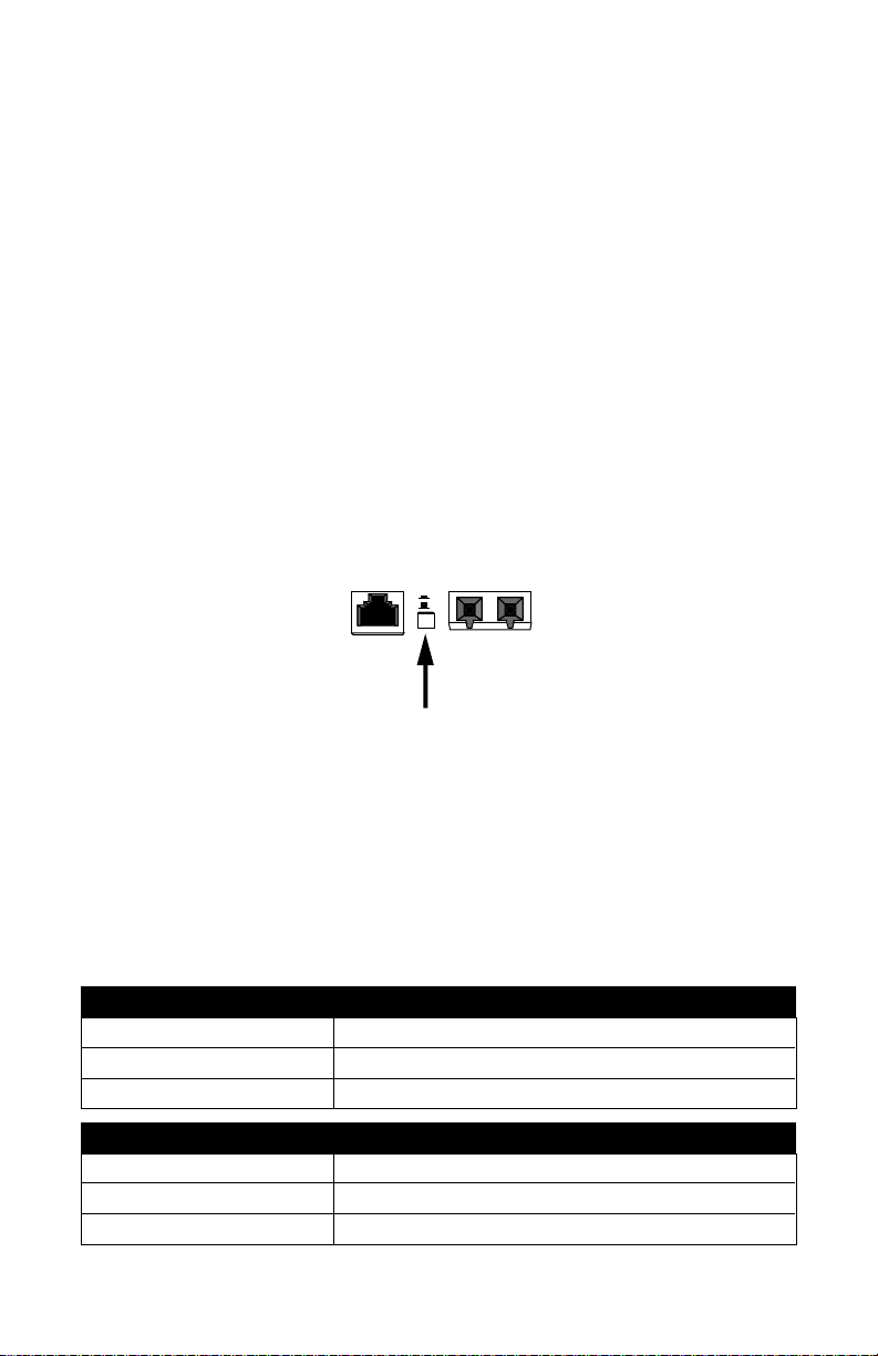
Link Loss Carry Forward Switch (LLCF)
The AutoTwister incorporates Link Loss Carry Forward (LLCF) functionality as an aid in troubleshooting remote connections. When LLCF is
enabled, the loss of inbound link pulses on a port stops the transmission
of outbound link pulses on the
enabled, the loss of incoming link pulses at
sion of link pulses out of
pulses,
Port 1
will not transmit link pulses.
opposite
Port 2
. Conversely, if
port. For example, if LLCF is
Port 1
will stop the transmis-
Port 2
stops receiving link
Link Loss Carry Forward is enabled on both ports when switch LLCF is
ON. The unit is shipped with LLCF disabled. Refer to Link Loss Carry
Forward in the User Guide section of this manual for further details.
Link Loss Return Switch (LLR2)
In addition to LLCF, the AutoTwister supports Link Loss Return functionality to help with troubleshooting remote connections.
Unlike LLCF, which applies to both ports on the AutoTwister, LLR only
affects the fiber optic port. When LLR is enabled, the loss of the inbound
link pulses on the port stops the transmission of outbound link pulses on
the
same
port. For example, if LLR is enabled on port 2 and its receiver
(RX) stops detecting link pulses, then port 2’s transmitter (TX) will stop
sending link pulses. LLR is not applicable to the copper port.
Link Loss Return is enabled on Port 2 when switch LLR2 is ON. The unit
is shipped with LLR disabled. Refer to Link Loss Return in the User
Guide section of this manual for more information.
Duplex Switch (FD1, FD2)
*
Switch FD1 determines the duplex mode for the copper port when autonegotiation is disabled. When auto-negotiation is enabled, the FD1
switch setting is ignored. Switch FD2 determines the duplex mode on the
*Changes to switches FD1 and FD2 only come into effect after the power-cycle initialization.
Installation Guide 7

fiber optic port. A port operates at full duplex when its FD switch is ON. It
operates at half duplex when its FD switch is OFF. The default is full
duplex enabled.
Speed Switch (100M1)
*
Switch 100M1 controls the speed setting for the copper port. If autonegotiation is disabled, the port speed will be the same as this switch
setting, where ON is 100Mbps and OFF is 10Mbps. The default speed
setting is 100Mbps. When auto-negotiation is enabled, the 100M1 switch
setting is ignored.
Auto-Negotiation Switch (AN1)
*
Switch AN1 controls the use of auto-negotiation on the copper port. To
enable auto-negotiation, set the switch ON. To disable the function, set
the switch OFF. By default, auto-negotiation is enabled.
When the copper port has auto-negotiation enabled, it advertises
100Mbps full duplex capabilities. When auto-negotiation is disabled, the
port’s duplex is set by the FD1 switch, and its speed is set by the 100M1
switch.
DIP Switch Configuration Table
Use the following table to help you set the DIP switches to obtain specific
modes of operation. The configuration column lists the speed and duplex
options for the copper port (Port 1) on the left and the fiber port (Port 2)
on the right. “Auto” indicates that auto-negotiation is enabled.
noitarugifnoC
)2troP-1troP(
xelpuDlluFspbM001-otuAANNOANNO
xelpuDflaHspbM001-otuAANNOANFFO
xelpuDflaHspbM001-xelpuDflaHspbM01FFOFFOFFOFFO
xelpuDlluFspbM001-xelpuDflaHspbM01FFOFFOFFONO
xelpuDflaHspbM001-xelpuDlluFspbM01NOFFOFFOFFO
xelpuDlluFspbM001-xelpuDlluFspbM01NOFFOFFONO
xelpuDlluFspbM001-xelpuDlluFspbM001NOFFONONO
*Changes to switches 100M1 and AN1 only come into effect after the power-cycle initialization.
8 Metrobility 10/100Mbps Delta Class AutoTwister
1DF1NA1M0012DF
xelpuDflaHspbM001-xelpuDflaHspbM001FFOFFONOFFO
xelpuDlluFspbM001-xelpuDflaHspbM001FFOFFONONO
xelpuDflaHspbM001-xelpuDlluFspbM001NOFFONOFFO
)reppoC(1troP)rebiF(2troP
Loading...