

M133-13,M133-14,M133-15,M133-16,M133-17,M133-1E,M133-1J,M133-1K,M133-1M,M133-1X,M133-1Y
Table of contents
 Loading...
Metrobility M133-13,M133-14,M133-15,M133-16,M133-17,M133-1E,M133-1J,M133-1K,M133-1M,M133-1X,M133-1Y User guide
100Mbps
“twister”™
METRO
optical systems
bility
PWR
LK
ACT
“twister”™
FD
LK
FEF
ACT
M133
LB FAIL
LB PASS
Installation and User’s Guide

This manual covers the following Metrobility
100Mbps Delta Class “twister” models:
M133-13 _______ 100Mbps TX to 100Mbps FX multimode SC
M133-14 _______ 100Mbps TX to 100Mbps FX singlemode SC
M133-15 _______ 100Mbps TX to 100Mbps FX multimode ST
M133-16 _______ 100Mbps TX to 100Mbps FX singlemode ST
M133-17 _______ 100Mbps TX to 100Mbps FX singlemode SC (40km)
M133-1E _______ 100Mbps TX to 100Mbps FX multimode MT-RJ
M133-1J _______ 100Mbps TX to 100Mbps FX singlemode SC (100km)
M133-1K _______ 100Mbps TX to 100Mbps FX multimode LC
M133-1M _______ 100Mbps TX to 100Mbps FX singlemode LC
M133-1X _______ 100Mbps TX to 100Mbps SC bidirectional wavelength
division multiplexed (BWDM) 1550/1310nm
M133-1Y _______ 100Mbps TX to 100Mbps SC BWDM 1310/1550nm
This publication is protected by the copyright laws of the United States and other countries, with all
rights reserved. No part of this publication may be reproduced, stored in a retrieval system, translated,
transcribed, or transmitted, in any form, or by any means manual, electric, electronic, electromagnetic,
mechanical, chemical, optical or otherwise, without prior explicit written permission of Metrobility Optical
Systems, Inc.
© 2002-2003 Metrobility Optical Systems, Inc. All rights reserved. Printed in USA.
Metrobility Optical Systems, the Metrobility Optical Systems logo, and “twister” are trademarks of
Metrobility Optical Systems, Inc.
The information contained in this document is assumed to be correct and current. The manufacturer is
not responsible for errors or omissions and reserves the right to change specifications at any time
without notice.

Contents
Overview........................................................................................4
Key Features............................................................................4
Installation Guide .........................................................................5
Unpack the “twister” and Accessories......................................5
Attach the Rubber Feet ............................................................5
Choose an Appropriate Location..............................................5
Set the Switches ......................................................................6
Connect to the Network............................................................8
Apply Power ...........................................................................11
User’s Guide ...............................................................................13
LED Indicators........................................................................13
Link Loss Carry Forward (LLCF)............................................14
Far End Fault (FEF) ...............................................................16
Remote Loopback ..................................................................17
Topology Solution...................................................................19
Technical Specifications.........................................................20
Product Safety, EMC, and Compliance Statements...............22
Warranty and Servicing..........................................................23

Overview
Sleek, compact, and rich in features, Metrobility’s 100Mbps Delta Class
“twister” looks as impressive as it operates. Designed for desktop use in
any modern office, the durable “twister” meets strict US and international
EMC regulations. This innovative device allows you to convert from
copper to fiber, extend copper-based network distances up to 100km,
and test the integrity of the fiber line using remote loopback on the fiber
port. New features include a wall mounting option, automatic MDI-X/MDIII capability, highly visible LEDs on the top, and built-in cable management and protection.
To optimize your Fast Ethernet network, the “twister” provides seamless
operation in full- and half-duplex environments. Full signal restoration
ensures accurate data transmission throughout the network. The “twister”
incorporates both Far End Fault and Link Loss Carry Forward, two
troubleshooting functions to help identify the loss of a remote network
connection.
On select models, bidirectional wavelength division multiplexing (BWDM)
offers an interface that carries two separate channels in different directions through a single strand of fiber. BWDM eliminates the need to
install a second fiber and effectively doubles the fiber capacity on existing fiber cables.
Key Features
• Link Loss Carry Forward
• Far End Fault notification
• Remote fiber loopback to test the entire fiber link
• Auto-negotiation on copper port
• Auto-crossover (i.e., no crossover cables to install or switches to set)
• Convenient LED indicators located on the top for high visibility
• Integral cable management and protection
•Wall mountable
• Far End Fault indicator on the fiber port
•Multiple connectivity options, including BWDM
• Fully compliant with IEEE 802.3 and 802.3u
• Stylish, contemporary design in a durable plastic case
4 Metrobility 100Mbps Delta Class “twister”

Installation Guide
Follow the simple steps outlined in this section to install and start using
the Metrobility 100Mbps Delta Class “twister” media converter.
Unpack the “twister” and Accessories
Check that the following parts are included in your box:
• 100Mbps Delta Class “twister”
• Power supply
• Power supply cord (North American shipments only)
• Four (4) rubber feet
Your order has been provided with the safest possible packaging, but
shipping damage occasionally does occur. Inspect your order carefully. If
you discover any shipping damage, notify your carrier and follow
instructions for damage and claims. Save the original shipping carton if
return or storage of the unit is necessary.
Attach the Rubber Feet
The “twister” is shipped with four rubber feet located on the black
adhesive strip. To install the rubber feet, first turn the “twister” upsidedown. Peel the feet from the adhesive strip, then attach one foot to each
circular indentation on the unit. This provides an air gap which helps to
cool the unit, and also adds stability for desktop operation.
If you are stacking the “twister” on top of another unit, the rubber feet
must be attached to the bottom of the “twister”.
Choose an Appropriate Location
The “twister” is intended for use in either an office or a residential
environment. The unit must be located within six (6) feet of the AC power
source being used and placed as far away as possible from electrical
noise generating equipment such as copiers, electrostatic printers, and
other motorized equipment. If exposed twisted-pair wiring is used nearby,
the wiring should be routed as far away as possible from power cords
and data cables to minimize interference.
Installation Guide 5
The unit may be oriented in any manner which allows you to make the
physical connection to the power supply and leaves a minimum of six (6)
inches of space for proper ventilation.
Wall Mounting
The “twister” requires no additional hardware for wall mounting. After
selecting an appropriate place for installation, simply align the 1/4"
keyhole opening on the bottom of the unit to a screw (6-32 maximum
head size) or wall anchor. Once you have it positioned properly, make
sure the device is attached securely.
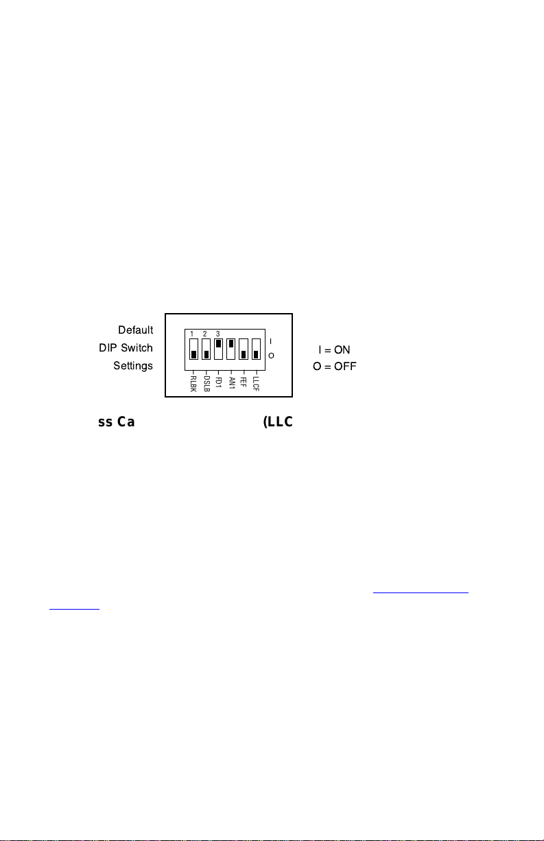
Set the Switches
The “twister” provides a set of six DIP switches located on the back
panel. These switches allow you to select from several modes of
operation. The default settings are shown below.
1 2 3 4 5 6
DSLB
RLBK
FD1
AN1
FEF
LLCF
Link Loss Carry Forward Switch (LLCF)
The “twister” incorporates Link Loss Carry Forward (LLCF) functionality
as an aid in troubleshooting remote connections. When LLCF is enabled,
the loss of inbound link pulses on a port stops the transmission of
outbound link pulses on the
enabled, the loss of incoming link pulses at
sion of link pulses out of
pulses,
Port 1
will not transmit link pulses.
opposite
Port 2
. Conversely, if
port. For example, if LLCF is
Port 1
will stop the transmis-
Port 2
stops receiving link
Link Loss Carry Forward is enabled on both ports when switch LLCF is
ON. The unit is shipped with LLCF disabled. Refer to Link Loss Carry
Forward in the User Guide section of this manual for further details.
Far End Fault Switch (FEF)
The “twister” supports Far End Fault functionality to detect the loss of link
by the remote unit’s fiber port receiver.
FEF is only applicable to the fiber port. When FEF is enabled on a port,
the loss of the inbound link pulses on that port generates an alarm, which
is sent out the port’s transmitter. FEF also enables a port to read the
alarm. To function properly, the FEF setting on both the local and remote
“twister” must be the same.
6 Metrobility 100Mbps Delta Class “twister”

For example, if FEF is enabled on both units and the remote unit’s fiber
receiver (RX) stops detecting link pulses, then its fiber transmitter (TX)
will send an alarm. The local “twister” will receive the alarm and report it
through its fiber port FEF LED, which will turn amber. No alarm will be
issued if FEF is disabled on the remote unit. The FEF LED will not turn
amber if FEF is disabled on the local “twister” because it will not be able
to detect the alarm.
Far End Fault is enabled on Port 2 when switch FEF is ON. The unit is
shipped with FEF disabled. Refer to Far End Fault in the User Guide
section of this manual for more information.
Auto-Negotiation Switch (AN1)
Switch AN1 controls the use of auto-negotiation on the copper port. Autonegotiation determines whether the port operates at half or full duplex.
When AN1 is enabled, the copper port will advertise full duplex capabilities to its connected device, if the duplex switch, FD1, is enabled. The
port will advertise half duplex capabilities if FD1 is disabled. If AN1 is
disabled, the duplex switch will determine the port’s duplex mode. By
default, auto-negotiation is enabled.
Duplex Switch (FD1)
Switch FD1 sets the duplex mode for the copper port when auto-negotiation is disabled. The copper port operates at full duplex when FD1 is
enabled; and it operates at half duplex when FD1 is disabled. If autonegotiation is enabled, the FD1 switch setting will determine whether the
port advertises full or half duplex (refer to Auto-Negotiation above). The
default is set to full duplex enabled.
Copper Port Configuration Table
Use the table below to set the duplex and auto-negotiation DIP
switches to obtain specific modes of operation for the copper port.
noitarugifnoCtroPreppoC1DF1NA
xelpuDlluFNOFFO
xelpuDflaHFFOFFO
xelpuDlluFetaitogeN-otuANONO
xelpuDflaHetaitogeN-otuAFFONO
Disable Loopback Switch (DSLB)
This switch determines the response of the fiber port when it receives the
remote loopback command. If the DSLB switch is enabled, the port will
ignore all remote loopback commands. When the switch is disabled, the
port will permit remote loopback to occur. By default, the response switch
is disabled, which allows remote loopback.
Installation Guide 7
Remote Loopback Switch (RLBK)
The remote loopback switch allows you to test the fiber connection between
a Metrobility Delta Class “twister” and a remote Metrobility x133 unit.
Enabling the switch sends a loopback request to the remote fiber port. To
run the loopback test properly , the following conditions must be met:
• The remote unit must be a Metrobility x133 standalone converter or
line card.
• The DSLB switch on the remote unit must be disabled.
If the conditions are satisfied, the remote loopback sequence will begin.
The remote fiber port will go into loopback mode. Next, the local “twister”
will generate a test pattern that is sent to the remote unit and then looped
back. The local “twister” will read the returned data to verify proper
transmission. The LB LED on the local “twister” will indicate whether the
test passed (green) or failed (amber). Refer to Remote Loopback for
further information.
If the two conditions for remote loopback are not met, the remote loopback
test will always fail. By default, remote loopback is disabled.
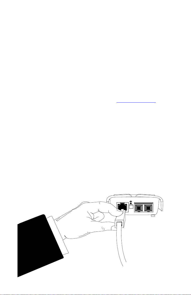
Connect to the Network
The Metrobility 100Mbps Delta Class “twister” offers the ease of plugand-play installation. The overhang extension provides built-in protection
for the two cable connectors.
When making network connections with the Metrobility “twister”, grasp
the end of the cable with your index finger on the top of the connector
and your thumb on the bottom, as shown in the illustration below. For
easier installation, insert the copper cable to the “twister” before connecting the fiber.
x
II
8 Metrobility 100Mbps Delta Class “twister”
Loading...