

7731-11-75,7731-13-75,7731-14-75,7731-15-75,7731-16-75,7731-17-75,7731-1J-75,7732-11-75,7711-11-75,7712-11-75
Metrobility 7731-11-75,7731-13-75,7731-14-75,7731-15-75,7731-16-75,7731-17-75,7731-1J-75,7732-11-75,7711-11-75,7712-11-75 User guide
Lancast
®
Intelligent 7500
“redundant twister”™ Module
“redundant twister”
R
ES
SECO
R
X
T
X
100 BASE
“redundant twister”
P
W
R
SW
R
ESET
SECO
N
D
AR
Y
R
LK
X
T
X
R
X
AT
T
X
100 BASE
PW
ET
N
D
A
R
Y
M
A
IN
PR
IM
A
R
10 BASE
“
M
AIN
PR
IM
R
X
T
X
T
T
LK
AT
AR
Y
LK
AT
100 BASE
“redundant twister”
P
R
ESET
SEC
O
N
D
A
R
Y
R
X
E
L
H
T
X
R
SW
LK
AT
“
LK
A
Y
LK
A
PWR
RESET
M
A
I
N
P
R
I
S
E
C
SEC
M
A
IN
W
R
SW
P
R
IM
A
R
Y
R
LK
X
E
AT
L
H
T
X
100 BASE
PWR
SW
LK
AT
LK
AT
LK
AT
“
LK
A
T
LK
A
T
SW
RESET
LK
M
A
AT
I
N
LK
P
R
AT
I
LK
S
E
AT
C
SEC
100 BASE
“redundant twister”
PW
R
SW
R
ES
ET
SECO
N
D
AR
Y
LK
R
X
L
H
T
X
R
X
AT
L
H
T
X
“
M
A
IN
LK
A
T
P
R
IM
A
R
Y
LK
AT
Installation & User Guide
100Mbps Models: 7731-11-75 / 7731-13-75 / 7731-14-75 / 7731-15-75 /
7731-16-75 / 7731-17-75 / 7731-1J-75 / 7732-11-75
10Mbps Models: 7711-11-75 / 7712-11-75

Lancast Intelligent “redundant twister” Modules
10Mbps without SONAR (Switch On No Activity Received)
7711-11-75 ___ RJ-45 to redundant RJ-45
100Mbps without SONAR
7731-11-75 ___ RJ-45 to redundant RJ-45
7731-13-75 ___ RJ-45 to redundant FX multimode SC
7731-14-75 ___ RJ-45 to redundant FX singlemode SC
7731-15-75 ___ RJ-45 to redundant FX multimode ST
7731-16-75 ___ RJ-45 to redundant FX singlemode ST
7731-17-75 ___ RJ-45 to redundant FX singlemode SC (40km)
7731-1J-75 ___ RJ-45 to redundant FX singlemode SC (100km)
10Mbps with SONAR
7712-11-75 ___ RJ-45 to redundant RJ-45
100Mbps with SONAR
7732-11-75 ___ RJ-45 to redundant RJ-45
This publication is protected by the copyright laws of the United States and other countries, with all rights
reserved. No part of this publication may be reproduced, stored in a retrieval system, translated, transcribed,
or transmitted, in any form, or by any means manual, electric, electronic, electromagnetic, mechanical,
chemical, optical or otherwise, without prior explicit written permission of Metrobility Optical Systems, Inc.
© 2002 Metrobility Optical Systems, Inc. All rights reserved. Printed in USA.

Table of Contents
Intelligent 7500 “redundant twister” Module Installation & User Guide
Overview .................................................................................................................... 4
Installation Guide ......................................................................................................7
STEP 1: Unpack the Intelligent “redundant twister” Module ....................... 7
STEP 2: Set the DIP Switches ..................................................................... 7
STEP 3: Set the MDI-II/MDI-X Switch ..................................................... 12
STEP 4: Install the Intelligent “redundant twister” Module ........................ 14
STEP 5: Connect to the Network ............................................................... 15
User Guide ............................................................................................................... 17
Module LED Operation............................................................................ 17
Reset Push Button .................................................................................... 18
Link Loss Carry Forward (LLCF)............................................................ 19
SONAR .................................................................................................... 20
Back-to-Back Application ........................................................................ 21
Topology Solution .................................................................................... 22
Technical Specifications........................................................................... 23
Product Safety, EMC and Compliance Statements .................................. 25
Warranty and Servicing ............................................................................ 26
Lancast is a registered trademark; Metrobility Optical Systems, the Metrobility Optical Systems logo,
NetBeacon, WebBeacon, and “redundant twister” are trademarks of Metrobility Optical Systems, Inc. Other
trademarks appearing in this manual are the property of their owners.
“redundant twister” technology is a patent of Metrobility Optical Systems, Inc.
The information contained in this document is assumed to be correct and current. The manufacturer is not
responsible for errors or omissions and reserves the right to change specifications at any time without notice.

Overview
The Lancast Intelligent 7500 “redundant twister” module offers the resiliency of
data link redundancy to ensure network integrity with no down time. This link
duplication provides the nonstop networking capability essential for high priority
traffic and mission-critical applications. The intelligent “redundant twister” modules
provide full redundant data paths for Ethernet or Fast Ethernet devices. The Fast
Ethernet intelligent “redundant twister” modules also provide 100BASE-TX to FX
conversion. The intelligent “redundant twister” module actively monitors the primary
link and if it fails, automatically activates the secondary link without interruption to
network operation.
The 7712-11-75 and 7732-11-75 incorporate SONAR (Switch On No Activity
Received). With SONAR enabled, the module provides protection against loss of
data activity in addition to link integrity.
The addition of management functionality allows communication between the
chassis and a management station providing software control over the intelligent
“redundant twister” module configuration and notification of a failure to the management station.
The intelligent “redundant twister” module has the following features:
• Can be configured to operate in Dynamic Recovery Mode (DRM) to
ensure session integrity and increased uptime.
• Can be configured to operate in Network Select Mode (NSM) to
redirect and isolate traffic adding extra security.
• Immediately switches over from the primary link to the secondary link
if the primary link fails.
• In addition to switching on loss of link, the 7712-11-75 and 7732-11-75
can be configured to switch on loss of data (SONAR).
• Provides minimal impact on the round trip delay for communication in
half-duplex collision domains.
• Fast Ethernet modules demonstrate a maximum loss of 2-3 packets
(measured with minimum packet size and minimum inter-packet gap)
during fail-over transition.
• All twisted-pair ports are equipped with an MDI-II to MDI-X switch to
eliminate the need for crossover cables.
4

• Can be configured to return automatically to the primary link after the
failure condition is resolved or only upon secondary failure; or manually switched back to primary after fail-over.
• Supports full- and half-duplex operation.
• Supports auto-polarity on all twisted-pair ports.
• In addition to providing link and data on the active ports, the 7732-1175 intelligent “redundant twister” modules can be configured to provide
link or link and redundant transmit data on the inactive port.
• Link Loss Carry Forward* enable/disable functionality.
• Functions with devices configured for auto-negotiation.
• Fused power on each module protects the system from a short circuit.
This prevents a faulty module from bringing down the entire system.
* Please refer to the page titled “Link Loss Carry Forward (LLCF)” in the User Guide section of
this document for more detailed information.
Intelligent “redundant twister” Module 5
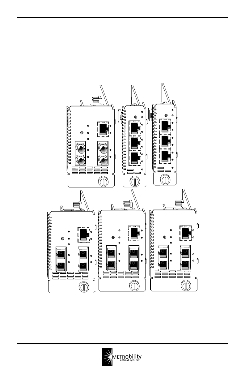
The Lancast Intelligent “redundant twister” module is available in 10 models and
can be installed in any Metrobility chassis. Each model contains a MAIN port, a
PRIMARY port and a SECONDARY port. Redundancy is provided between the
PRIMARY and SECONDARY ports. Because of the size of the intelligent “redundant twister” fiber optic modules, each TX-FX module uses two slots in the chassis.
The TX-TX module uses only one slot.
Model Number Mbps Connectors Maximum Supported Link Length
771x-11-75 10 RJ-45 to redundant RJ-45 100m/100m
773x-11-75 100 RJ-45 to redundant RJ-45 100m/100m
7731-13-75 100 RJ-45 to redundant FX multimode SC 100m/2km
7731-14-75 100 RJ-45 to redundant FX singlemode SC 100m/15km
7731-15-75 100 RJ-45 to redundant FX multimode ST 100m/2km
7731-16-75 100 RJ-45 to redundant FX singlemode ST 100m/15km
7731-17-75 100 RJ-45 to redundant FX singlemode SC 100m/40km
7731-1J-75 100 RJ-45 to redundant FX singlemode SC 100m/100km
1
0
0
B
A
S
E
PWR
SW
RESET
LK
M
A
AT
I
N
LK
P
R
AT
I
LK
S
E
AT
C
SEC
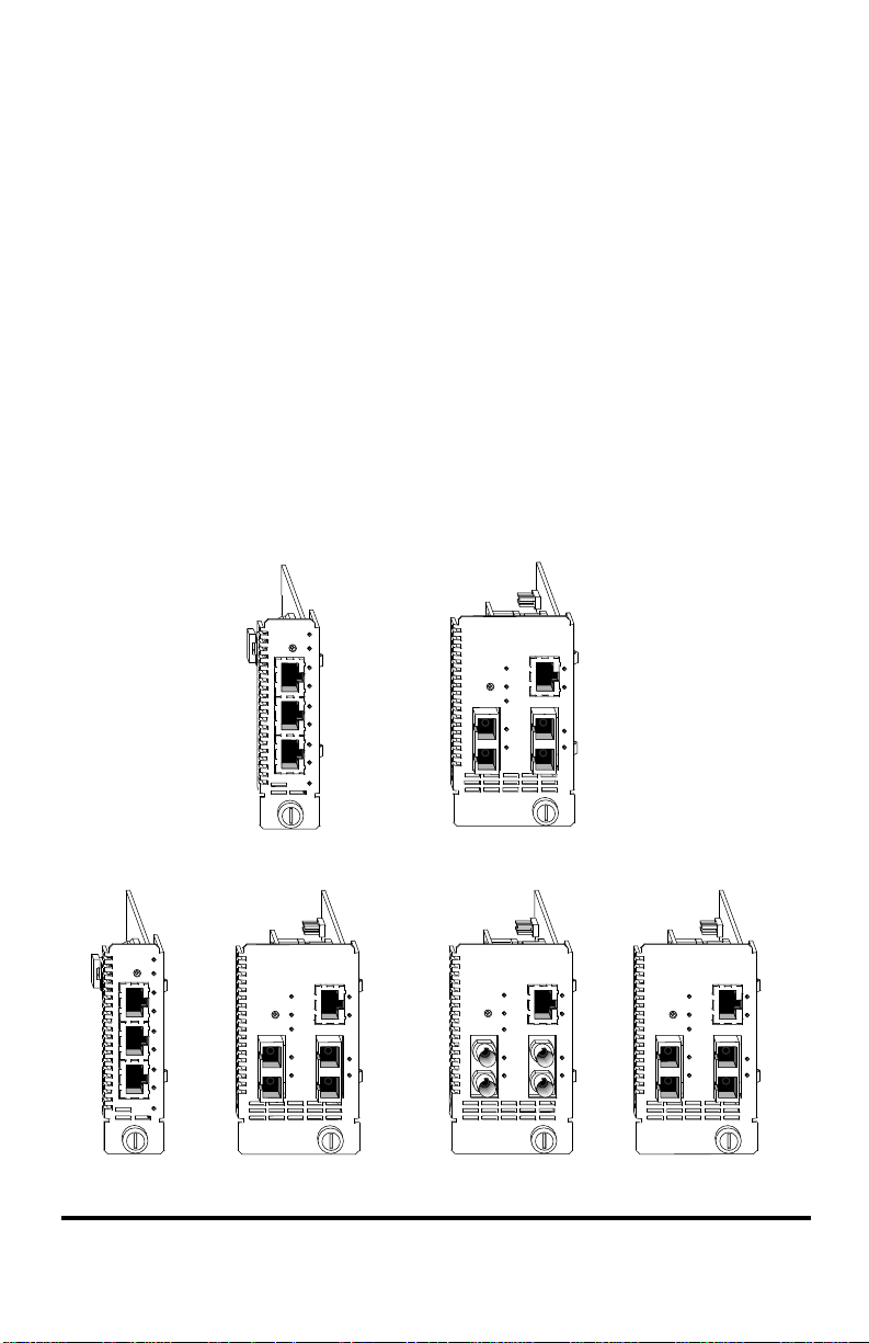
7731-11-75
7732-11-75
Port 1
Port 2
Port 3
1
0 B
A
S
E
PWR
SW
RESET
LK
M
A
AT
I
N
LK
P
R
AT
I
LK
S
E
AT
C
SEC
7711-11-75
7712-11-75
100 BASE
“redundant twister”
PWR
SW
RESET
SECONDARY
PRIMARY
R
LK
R
X
X
AT
T
T
X
X
7731-13-75
7731-14-75
100 BASE
“
MAIN
LK
PWR
SW
R
X
LK
E
AT
L
H
T
X
PRIMARY
Port 2
AT
LK
AT
Port 3
Port 1
“redundant twister”
RESET
SECONDARY
R
X
E
L
H
T
X
7731-1J-75
“
MAIN
LK
AT
LK
AT
100 BASE
“redundant twister”
PWR
SW
RESET
SECONDARY
R
LK
X
AT
T
X
R
X
T
X
MAIN
PRIMARY
“
LK
AT
LK
AT
7731-15-75
100 BASE
“redundant twister”
MAIN
PWR
SW
RESET
SECONDARY
PRIMARY
R
R
X
LK
X
L
L
AT
H
H
T
T
X
X
7731-17-75
“
LK
AT
LK
AT
7731-16-75
6 Installation Guide
Installation Guide
Follow the simple steps outlined in this section of the manual to install and start
using your Lancast intelligent “redundant twister” module.
NOTE: Electrostatic discharge precautions should be taken when handling any
module. Proper grounding is recommended (i.e., wear a wrist strap).
Unpack the Intelligent “redundant twister” Module
Your order has been provided with the safest possible packaging, but
1
shipping damage does occasionally occur. Inspect your order carefully for
damage that may have occurred during shipment. If you discover any
shipping damage, notify the carrier and follow their instructions for damage
and claims. Save the original shipping carton if return or storage of the unit is
necessary.
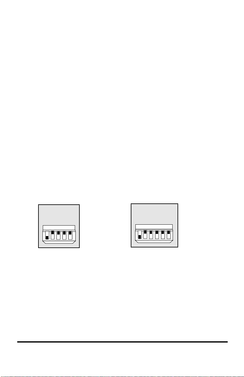
Set the DIP Switches
A set of DIP switches, located on the module board, provide user-selectable
2
configurability options for several modes of operation. These switches are
clearly marked on the module’s printed circuit board. Refer to the table on
the following pages for the proper setting of the DIP switches.
*
RED
LLCF
LINK
AUTO
TX
RED
LLCF
LINK
AUTO
54321
DOWN
7711-11-75 7712-11-75
7731-XX-75 7732-11-75
* DIP switches can also be managed via console commands or through Metrobility’s NetBeacon™ or
WebBeacon™ management software. Refer to the
Reference Guide, NetBeacon™ Element Management Software Installation & User Guide
con™ Management Software Installation & User Guide
TX
UP
Lancast Intelligent 7500 Command Line Interface
Intelligent “redundant twister” Module 7
65432
DOWN
UP
for software management information.
SONR
1
or
WebBea-

7711-11-75 and 7731-xx-75: The DIP switches for these modules can be set
for the following operational functions:
Switch Name Position* Operation
TX UP Transmits data on both the PRIMARY and
SECONDARY ports simultaneously. LINK must
be enabled on both ports. For 100Mbps units, it is
only applicable in Dynamic Recovery Mode (DRM).
DOWN Transmits data on the active port only.
(default)
AUTO UP In DRM, automatically reverts the active port back
to the PRIMARY port when the primary link is reestablished.
In Network Select Mode (NSM), sets the default
active port to SECONDARY.
DOWN In DRM, does not revert the active port back to the
(default) PRIMARY port when a primary link is reestablished
until the SECONDARY link fails. If the SECONDARY link does not fail, the SECONDAR Y port remains active. Use the RESET push button located on
the front of the module to force the active port back to
thePRIMARY port and to clear the SW LED.
In NSM, sets the default active port to PRIMARY.
LINK UP Link signals are sent out on both the PRIMARY and
SECONDARY ports (i.e. link is sent out both ports).
For 100Mbps units, it is only applicable in DRM.
DOWN Link signals are sent out on the active port only.
(default) With the LINK switch in this position, data is not
transmitted out the inactive port regardless of the
TX switch setting.
LLCF UP Link Loss Carry Forward is enabled.
DOWN Link Loss Carry Forward is disabled.
(default)
* When setting the DIP switches, the UP position is when the DIP switch lever is pushed away from the circuit
board. The DOWN position is when the DIP switch lever is pushed toward the printed circuit board.
8 Installation Guide
Switch Name Position Operation
RED UP Operates in Dynamic Recovery Mode. If the
(default) PRIMARY link fails, the SECONDARY port be-
comes active. Refer to the description of the AUTO
switch.
DOWN Operates in Network Select Mode. Use the
RESET push button to toggle between PRIMARY
and SECONDARY. In NSM, the AUTO switch sets
the initial active port on power up. Up is SECONDARY and down is PRIMARY.
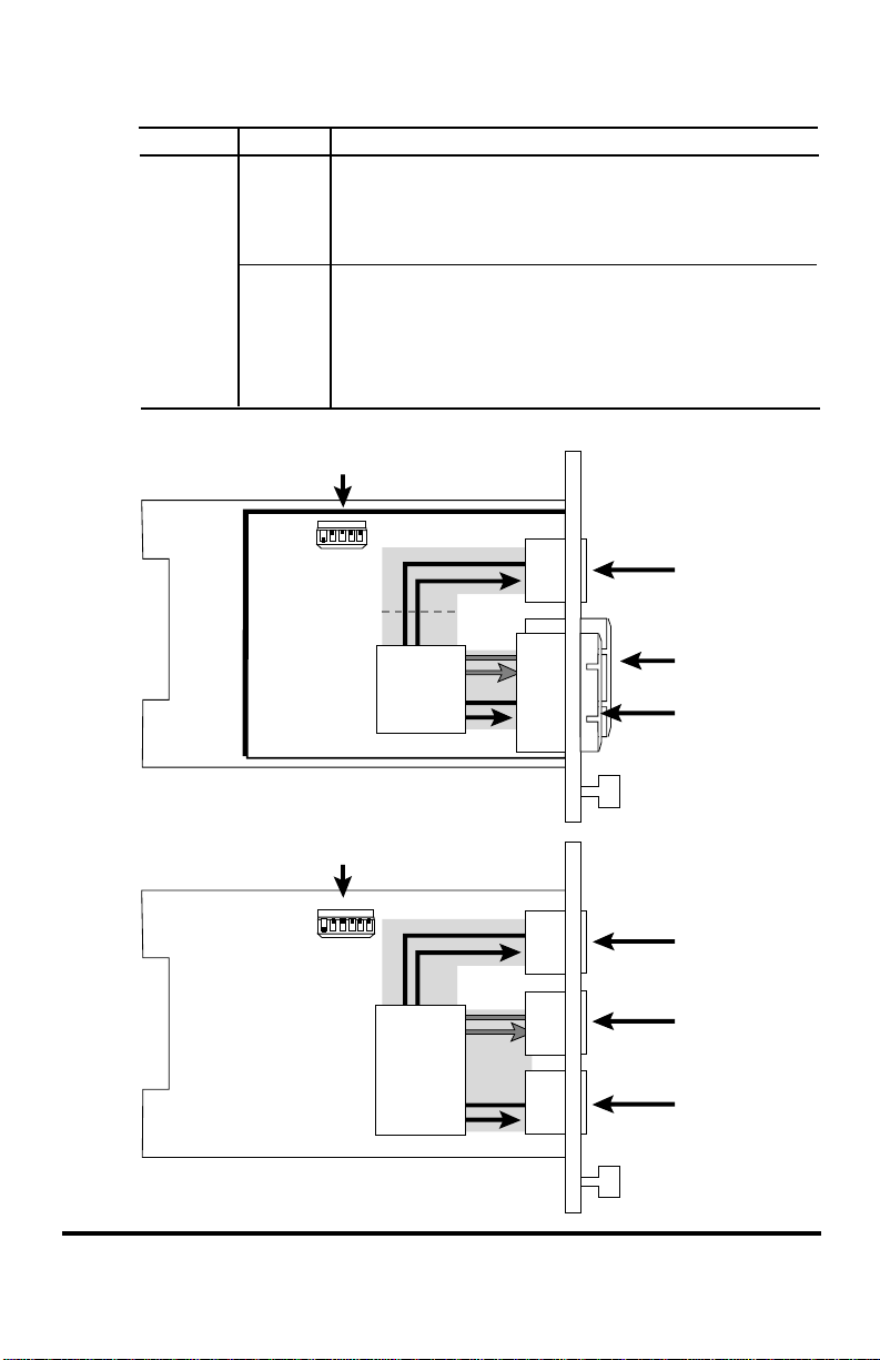
DIP Switches
43
5
21
TX
RED
LINK
LLCF
AUTO
RJ-45
FX SC (ST)
FX SC (ST)
DIP Switches
54321
6
TX
RED
LINK
LLCF
AUTO
SONR
Intelligent “redundant twister” Module 9
RJ-45
RJ-45
RJ-45
 Loading...