

2643-13-01,2643-14-01,2643-15-01,2643-16-01,2643-17-01,2643-1E,2643-1G-01,2643-1J-01,2643-1K-01,2643-1M-01,2643-1X-01,2643-1Y-01
Metrobility 2643-13-01,2643-14-01,2643-15-01,2643-16-01,2643-17-01,2643-1E,2643-1G-01,2643-1J-01,2643-1K-01,2643-1M-01,2643-1X-01,2643-1Y-01 User guide
10/100 AutoT wister
™
“twister”
100BASE-FX 10/100BASE-TX
x
II
LKTXRX LKTX RX
MM
2643
100
FD
PWR
™
100BASE-FX
LK
RX
TX
BWDM
100BASE-FX
TX
100BASE-FX
TX
100BASE-FX 10/100BASE-TX
TX
TX
x
II
LK
RX
TX
MM
x
II
LK
RX
SM
LK
RX
TX
MM
“twister”
10/100BASE-TX
x
II
LK
“twister”
10/100BASE-TX
LK
“twister”
10/100BASE-TX
LK
TX
“twister”
x
II
LK
™
2643
100
FD
RX
PWR
™
2643
100
FD
RX
PWR
™
2643
100
FD
RX
PWR
™
2643
100
FD
RX
PWR
100BASE-FX
TX
100BASE-FX 10/100BASE-TX
TX
100BASE-FX 10/100BASE-TX
TX
100BASE-FX 10/100BASE-TX
TX
10/100BASE-TX
x
II
LK
RX
TX
MM
x
II
LK
RX
TX
SM
x
II
LK
RX
TX
SM PWR
x
II
LK
RX
TX
MM
“twister”
RX
LK
“twister”
LK
RX
“twister”
LK
RX
“twister”
RX
LK
™
2643
100
FD
PWR
™
2643
100
FD
PWR
™
2643
100
FD
™
2643
100
FD
PWR
Installation & User Guide
Models: 2643-13-01 / 2643-14-01 / 2643-15-01 / 2643-16-01 /
2643-17-01 / 2643-1E / 2643-1G-01 / 2643-1J-01 /
2643-1K-01 / 2643-1M-01 / 2643-1X-01 / 2643-1Y-01

Metrobility 10/100 AutoTwisters
2643-13-01 ___ 10/100Base-TX to 100Base-FX multimode SC
2643-14-01 ___ 10/100Base-TX to 100Base-FX singlemode SC
2643-15-01 ___ 10/100Base-TX to 100Base-FX multimode ST
2643-16-01 ___ 10/100Base-TX to 100Base-FX singlemode ST
2643-17-01 ___ 10/100Base-TX to 100Base-FX singlemode SC (40km)
2643-1E-01 ___ 10/100Base-TX to 100Base-FX multimode MT-RJ
2643-1G-01 ___ 10/100Base-TX to 100Base-FX multimode VF-45
2643-1J-01 ___ 10/100Base-TX to 100Base-FX singlemode SC (100km)
2643-1K-01 ___ 10/100Base-TX to 100Base-FX multimode LC
2643-1M-01___ 10/100Base-TX to 100Base-FX singlemode LC
2643-1X-01 ___ 10/100Base-TX to 100Base-FX singlemode 1550/1310nm
bidirectional wavelength division multiplexed (BWDM) SC
2643-1Y-01 ___ 10/100Base-TX to 100Base-FX singlemode 1310/1550nm
BWDM SC
This publication is protected by the copyright laws of the United States and other countries, with all rights
reserved. No part of this publication may be reproduced, stored in a retrieval system, translated, transcribed,
or transmitted, in any form, or by any means manual, electric, electronic, electromagnetic, mechanical,
chemical, optical or otherwise, without prior explicit written permission of Metrobility Optical Systems, Inc.
© 2002-2003 Metrobility Optical Systems, Inc. All rights reserved. Printed in USA.

Table of Contents
10/100 AutoTwister Installation & User Guide
Overview ................................................................................................................... 4
Installation Guide ..................................................................................................... 5
STEP 1: Unpack the AutoTwister and Accessories................................... 5
STEP 2: Choose an Appropriate Location ................................................ 5
STEP 3: Set the Switches .......................................................................... 5
STEP 4: Connect to the Network .............................................................. 9
STEP 5: Apply Power.............................................................................. 11
User Guide .............................................................................................................. 13
LED Indicators ........................................................................................ 13
Factory Settings....................................................................................... 14
Link Loss Return (LLR).......................................................................... 15
Link Loss Carry Forward (LLCF)........................................................... 16
Auto-Recovery ........................................................................................ 17
Auto-Recovery Application Example ..................................................... 18
Topology Solutions ................................................................................. 19
Technical Specifications.......................................................................... 20
Product Safety, EMC and Compliance Statements ................................. 22
Warranty and Servicing ........................................................................... 23
Metrobility Optical Systems, the Metrobility Optical Systems logo, “twister” and AutoTwister are trademarks of
Metrobility Optical Systems, Inc.
The information contained in this document is assumed to be correct and current. The manufacturer is not
responsible for errors or omissions and reserves the right to change specifications at any time without notice.

Overview
The Metrobility 10/100 AutoTwister provides seamless migration between
Ethernet and Fast Ethernet networks, in addition to built-in media conversion
allowing high-speed integration of fiber optic and twisted-pair segments. A complete
set of LEDs allows for quick status verification, and a bank of DIP switches provides
added versatility on each port. To optimize your Ethernet network, each port operates
independently in either half or full duplex.
The 10/100 AutoTwisters offer the following key features:
• Auto-negotiation switch on the twisted-pair interface.
• Half to full duplex conversion.
• Link loss auto-recovery on the fiber optic port.
• Link Loss Return (LLR) functionality to aid in troubleshooting a remote
network connection on the fiber optic port.
• Link Loss Carry Forward (LLCF) functionality to aid in troubleshooting a
remote network connection.
• An MDI-II to MDI-X switch that eliminates the need for crossover cables
on the twisted-pair port.
• Full-duplex flow control on each port.
• Store-and-forward switching to improve overall network performance by
buffering packets during times of heavy congestion and to prevent the
forwarding of corrupted packets.
• High-performance switching engine that performs forwarding and filtering
at full wire speed (148,800 packets per second).
• The ability to learn up to 1,024 MAC addresses.
• Low last-bit-in to first-bit-out delay.
• Discards packets with CRC or alignment errors, short packets (less than 64
bytes), or long packets (more than 1518 bytes for un-tagged frames and
more than 1522 bytes for IEEE 802.3ac tagged frames).
• VLAN tagging support.
• 128K bytes of buffer memory.
• Full compliance with applicable sections of IEEE 802.3, IEEE 802.3u, and
IEEE 802.3x.
4

Installation Guide
Follow the simple steps outlined in this section of the guide to install and start
using the Metrobility 10/100 AutoTwister.
Unpack the AutoTwister and Accessories
Check that the following components have been included:
1
• 10/100 AutoT wister
• Power supply
• Power cord
• Four (4) rubber feet
Your order has been provided with the safest possible packaging, but
shipping damage does occasionally occur. Inspect your order carefully. If
you discover any shipping damage, notify your carrier and follow their
instructions for damage and claims. Save the original shipping carton if
return or storage of the unit is necessary.
Choose an Appropriate Location
The 10/100 AutoTwister is intended for use in either office or industrial
2
environments. The unit must be located within six (6) feet of the AC power
source being used and placed as far away as possible from electrical noise
generating equipment such as copiers, electrostatic printers and other
motorized equipment. If exposed twisted-pair wiring is used nearby, the
wiring should be routed as far away as possible from power cords and data
cables to minimize interference.
3
The units may be oriented in any manner which allows you to make
physical connection to the power supply and leaves a minimum of six (6)
inches of space for proper ventilation.
Set the Switches
MDI-II to MDI-X Switch
To eliminate the need for crossover cables, the 10/100 AutoTwister includes
an MDI-II to MDI-X switch for the twisted-pair port. This push-button
switch is located in the center of the front panel and allows setup in either
straight-through or crossover configurations. (See Figure 1.)
10/100 AutoTwister 5
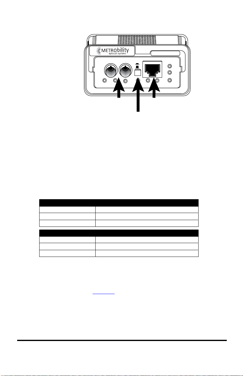
Figure 1.
™
2643
100
FD
RX
PWR
LKTXRX LK
Port 2
“twister”
x
II
TX
Port 1
MDI-II to MDI-X Switch
When setting the switch, observe the positioning of the following symbols:
• The parallel symbol (II) indicates a straight through or parallel connec-
tion. Switch is out. (default)
• The cross symbol (X) indicates a crossover connection. Switch is in.
Use the tables below as a guide.
A device that is wired straight through needs one crossover connection:
If the cable is
straight through
crossover
A device that is wired crossover needs a parallel connection:
If the cable is
straight through
crossover
the MDI-II to MDI-X Switch Setting should be
X
II
the MDI-II to MDI-X Switch Setting should be
II
X
DIP Switches
The 10/100 AutoTwister includes a set of six DIP switches located on the
back of the unit. (See Figure 2.) These switches allow you to select the
operational mode best suited to your network’s configuration.
When setting DIP switches, the ON position is when the DIP switch is
pushed up toward the top of the unit. The OFF position is when the DIP
switch is pushed down toward the bottom.
6 Installation Guide
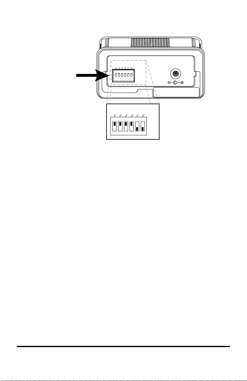
Figure 2.
DIP
switches
default
settings
FD1
FD1
AN1
FD2
100M1
LLR2
LLCF
AN1
100M1
FD2
ON
OFF
LLR2
PWR
DC INPUT/5VDC
LLCF
ON
OFF
Auto-Negotiation Switch (AN1)
*
Switch AN1 controls the use of auto-negotiation on the copper port. To
enable auto-negotiation, set the switch ON. To disable this function, set the
switch OFF. By default, auto-negotiation is enabled.
When the copper port has auto-negotiation enabled, it advertises 100Mbps
full duplex capabilities. When auto-negotiation is disabled, the port’s duplex
is determined by the FD1 switch, and its speed is set by the 100M1 switch.
10/100Mbps Switch (100M1)
*
Switch 100M1 controls the speed setting for the copper port. If autonegotiation is disabled, the port speed will be the same as this switch
setting, where ON is 100Mbps and OFF is 10Mbps. The default speed
setting is 100Mbps. When auto-negotiation is enabled, the 100M1 switch
setting is ignored.
Half/Full Duplex Switch (FD1, FD2)
Switch FD1 determines the duplex mode for the copper port if autonegotiation is disabled. When auto-negotiation is enabled, the FD1 switch
setting is ignored. Switch FD2 determines the duplex mode on the fiber
optic port. A port operates at full duplex when its FD switch is ON. It
operates at half duplex when its FD switch is OFF. The default is full duplex
enabled.
*
*Changes to switches AN1, 100M1, FD1 and FD2 only come into effect after the power-cycle
initialization.
10/100 AutoTwister 7

Link Loss Return Switch (LLR2)
The 10/100 AutoTwister incorporates Link Loss Return (LLR) functionality
as an aid in troubleshooting remote connections on its fiber optic port.
When LLR is enabled, the loss of the inbound link pulses on the port stops
the transmission of outbound link pulses on the same port. For example, if
LLR is enabled on port 2 and its receiver (RX) stops detecting link pulses,
then port 2’s transmitter (TX) will stop sending link pulses. LLR is not
applicable to the copper port.
Link Loss Return is enabled on Port 2 when switch LLR2 is ON. The unit is
shipped with LLR disabled. Refer to Link Loss Return in the User Guide
section of this manual for more information.
Link Loss Carry Forward Switch (LLCF)
In addition to LLR, the AutoTwister supports Link Loss Carry Forward
functionality to help with troubleshooting remote connections.
Unlike LLR, which only applies to the fiber port, LLCF affects both ports
on the AutoTwister. When LLCF is enabled, the loss of inbound link pulses
on a port stops the transmission of outbound link pulses on the opposite
port. For example, if LLCF is enabled, the loss of incoming link pulses at
Port 1 will stop the transmission of link pulses out of Port 2. Conversely, if
Port 2 stops receiving link pulses, Port 1 will not transmit link pulses.
Link Loss Carry Forward is enabled on both ports when switch LLCF is
ON. The unit is shipped with LLCF disabled. Refer to Link Loss Carry
Forward in the User Guide section of this manual for further details.
Use the following table to set the DIP switches to obtain specific modes of
operation. The configuration column lists the speed and duplex options for
Port 1 on the left and Port 2 on the right. “Auto” denotes that auto-negotiation is enabled.
8 Installation Guide
 Loading...